EP1594016B1 - Band, Bilderzeugungsgerät , und Verfahren zur Bandgeschwindigkeitskontrolle - Google Patents
Band, Bilderzeugungsgerät , und Verfahren zur Bandgeschwindigkeitskontrolle Download PDFInfo
- Publication number
- EP1594016B1 EP1594016B1 EP20050252414 EP05252414A EP1594016B1 EP 1594016 B1 EP1594016 B1 EP 1594016B1 EP 20050252414 EP20050252414 EP 20050252414 EP 05252414 A EP05252414 A EP 05252414A EP 1594016 B1 EP1594016 B1 EP 1594016B1
- Authority
- EP
- European Patent Office
- Prior art keywords
- belt
- speed
- degradation
- scale
- marks
- Prior art date
- Legal status (The legal status is an assumption and is not a legal conclusion. Google has not performed a legal analysis and makes no representation as to the accuracy of the status listed.)
- Ceased
Links
- 238000000034 method Methods 0.000 title claims description 52
- 230000015556 catabolic process Effects 0.000 claims description 62
- 238000006731 degradation reaction Methods 0.000 claims description 62
- 238000001514 detection method Methods 0.000 claims description 21
- 239000003086 colorant Substances 0.000 claims description 8
- 238000012546 transfer Methods 0.000 description 125
- 238000012937 correction Methods 0.000 description 47
- 230000008569 process Effects 0.000 description 32
- 230000000630 rising effect Effects 0.000 description 15
- 230000006870 function Effects 0.000 description 11
- 230000008021 deposition Effects 0.000 description 7
- 230000015572 biosynthetic process Effects 0.000 description 5
- 230000008859 change Effects 0.000 description 5
- 238000003384 imaging method Methods 0.000 description 4
- 230000002159 abnormal effect Effects 0.000 description 3
- 239000002131 composite material Substances 0.000 description 3
- 238000005516 engineering process Methods 0.000 description 3
- 239000011521 glass Substances 0.000 description 3
- 238000003825 pressing Methods 0.000 description 3
- 238000012545 processing Methods 0.000 description 3
- 210000000078 claw Anatomy 0.000 description 2
- 238000004140 cleaning Methods 0.000 description 2
- 238000010586 diagram Methods 0.000 description 2
- 238000005259 measurement Methods 0.000 description 2
- 230000003287 optical effect Effects 0.000 description 2
- 238000000926 separation method Methods 0.000 description 2
- 230000005856 abnormality Effects 0.000 description 1
- 238000010276 construction Methods 0.000 description 1
- 230000003111 delayed effect Effects 0.000 description 1
- 239000013013 elastic material Substances 0.000 description 1
- 238000002474 experimental method Methods 0.000 description 1
- 239000000463 material Substances 0.000 description 1
- 238000012986 modification Methods 0.000 description 1
- 230000004048 modification Effects 0.000 description 1
- 229920005668 polycarbonate resin Polymers 0.000 description 1
- 239000004431 polycarbonate resin Substances 0.000 description 1
- 229920001721 polyimide Polymers 0.000 description 1
- 239000009719 polyimide resin Substances 0.000 description 1
- 230000004044 response Effects 0.000 description 1
- 238000006748 scratching Methods 0.000 description 1
- 230000002393 scratching effect Effects 0.000 description 1
Images


Classifications
-
- G—PHYSICS
- G03—PHOTOGRAPHY; CINEMATOGRAPHY; ANALOGOUS TECHNIQUES USING WAVES OTHER THAN OPTICAL WAVES; ELECTROGRAPHY; HOLOGRAPHY
- G03G—ELECTROGRAPHY; ELECTROPHOTOGRAPHY; MAGNETOGRAPHY
- G03G15/00—Apparatus for electrographic processes using a charge pattern
- G03G15/14—Apparatus for electrographic processes using a charge pattern for transferring a pattern to a second base
- G03G15/16—Apparatus for electrographic processes using a charge pattern for transferring a pattern to a second base of a toner pattern, e.g. a powder pattern, e.g. magnetic transfer
Definitions
- the present invention relates to a belt device that detects an actual belt speed and corrects a belt speed based on the actual belt speed, an image forming apparatus including the belt device, and a method to control belt speed.
- Image forming apparatuses such as copying machines and printers capable of forming a full color image are increasing with the demands of the market.
- Such an image forming apparatus includes a so-called tandem type image forming apparatus.
- This type of image forming apparatus includes a plurality of photosensitive elements that are arranged in tandem, and a plurality of developing devices that develop toners of different colors corresponding to the photosensitive elements.
- toner images each having a single color are formed on the photosensitive elements, and the toner images of the single colors are sequentially transferred to a belt-shaped or a drum-shaped intermediate transfer element to form a full-color composite image.
- the tandem type image forming apparatus may include a direct transfer system and an indirect transfer system.
- toner images formed on photosensitive elements 91Y, 91M, 91C, and 91K aligned in a row are sequentially transferred, by transfer devices 92, to a sheet of paper P (hereinafter, "sheet P") carried on a sheet conveying belt 93 that rotates in the direction of arrow A, and a full color image is formed on the sheet P.
- sheet P a sheet of paper P carried on a sheet conveying belt 93 that rotates in the direction of arrow A
- toner images formed on the photosensitive elements 91Y, 91M, 91C, and 91K are sequentially transferred by superimposing, to an intermediate transfer belt 94 that rotates in the direction of arrow B.
- the toner images on the intermediate transfer belt 94 are collectively transferred to the sheet P, by a secondary transfer device 95.
- a paper feed device 96 and a fixing device 97 are also shown in Fig. 12 and Fig. 13 .
- toner images of different colors formed on the photosensitive elements are superimposed on one another on the intermediate transfer belt to form a color image. Therefore, if positions on which the images are superimposed deviate from one another, color misalignment or a slight change in hue may occur in the color image. Thus, image quality degrades. Accordingly, the positional deviation (color misalignment) of the color toner images is a key problem.
- Japanese Patent Application Laid Open No. H11-24507 pages 3 to 4, Fig. 1 discloses a technology to correct unevenness in speed of a transfer belt in a color image forming apparatus using a conventional transfer belt.
- a color copying machine includes an intermediate transfer belt (or transfer belt) that is rotatably supported by five support rollers including one drive roller. Toner images of four colors of cyan, magenta, yellow, and black are sequentially transferred by superimposing to the circumferential surface of the intermediate transfer belt to form a full color image.
- a scale with finely and accurately formed scale marks is provided on the internal surface of the intermediate transfer belt of the color copying machine.
- An optical detector (sensor) reads the scale to accurately detect the moving speed of the intermediate transfer belt. The moving speed detected is fed back by a feedback control system so that the intermediate transfer belt is made to move at an accurately controlled speed.
- the scale may be worn out, damaged, or even dirty due to deposition of toner thereon, when the color copying machine is configured. Further, the scale with the scale marks formed along the belt is read by a sensor, the speed of the belt is detected based on information for the scale read, and the result of detection is fed back to controller so that the belt is made to move at an accurate speed. If the scale is worn out, damaged or dirty, the sensor may erroneously detect the scale mark(s) of the scale, thereby making it difficult to accurately control the belt speed.
- JP2004-021236 JP11- 024507 and US 2004/022557 .
- a belt device includes an endless moveable belt with a scale formed thereon along a circumference, the scale includes a plurality of marks; a first sensor that detects a first speed of the belt based on detection of the marks; a first belt-speed controlling unit that controls a speed of the belt based on the first speed; a second sensor that detects a second speed of the belt based on a method other than detection of the marks; a second belt-speed controlling unit that controls a speed of the belt based on the second speed; a scale-mark degradation determining unit that determines whether there is a degradation in the quality of the marks and detects an amount of degradation upon determining that there is a degradation in the quality of the marks; and a belt drive controller that causes the first belt-speed controlling unit to control a speed of the belt if the amount of degradation detected by the scale-mark degradation determining unit is less than a predetermined value, and causes the second belt-speed controlling unit to control a speed of the belt if the amount of degradation detected by
- An image forming apparatus includes the above belt device; and a plurality of photosensitive elements that individually carry toner images of different colors, and that are made to rotate.
- the toner images of the different colors formed on the photosensitive element are sequentially transferred to the belt in a superimposed manner.
- a method of performing speed control of an endless movable belt, which provided with a scale formed thereon along a circumference and the scale includes a plurality of marks includes detecting a first speed of the belt based on detection of the marks; detecting a second speed of the belt based on a method other than detection of the marks; determining whether there is a degradation in the quality of the marks and detecting an amount of degradation upon determining that there is a degradation in the quality of the marks; and controlling a speed of the belt based on the first speed if the amount of degradation detected at the determining is less than a predetermined value, and controlling a speed of the belt based on the second speed if the amount of degradation is not less than the predetermined value.
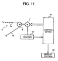
- Fig. 1 illustrates a belt device with a belt-speed control system according to an embodiment of the present invention.
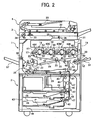
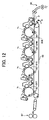
- Fig. 2 illustrates an example of an entire color copying machine that is an image forming apparatus, including the belt device.
- Fig. 3 is a block diagram of a belt-speed control system for an intermediate transfer belt of the color copying machine.
- a belt device 20 includes an intermediate transfer belt 10 that is an endless belt with a scale 5 formed along the whole circumference thereof, and that rotates in the direction of arrow C, the scale 5 having a plurality of scale marks formed thereon as shown in Fig. 1 (only few of the scale marks are shown in Fig. 1 ).
- the belt device 20 also includes a sensor 6 that reads the scale 5, and a control device 70 that detects an actual belt speed of the intermediate transfer belt 10 from information for the scale 5 read by the sensor 6, to correct a belt speed of the intermediate transfer belt 10 based on the actual belt speed detected.
- the control device 70 includes a motor controller 73 (see Fig. 3 ) that functions as a scale-mark degradation determining unit. Based a signal from the sensor 6, the motor controller 73 determines how a slit portion 5a (see Fig. 4 and Fig. 5 ), which is a scale mark of the scale 5, is degraded.
- the motor controller 73 also functions as a belt drive controller that performs belt speed correction for a degraded portion (explained later) when determining the degradation, and continues the process until the determination of the degradation is stopped. The functions are explained in detail later.
- the belt device 20 is installed in the color copying machine that is the image forming apparatus, and serves as an intermediate transfer device.
- the color copying machine is a tandem type electrophotographic device that uses the intermediate transfer belt 10, and a body 1 of the copying machine is placed on a paper feed table 2.
- a scanner 3 is mounted on the body 1, and an automatic document feeder (ADF) 4 is mounted on the scanner 3.
- ADF automatic document feeder
- the belt device 20 having the intermediate transfer belt 10 is provided at a substantially central part of the body 1.
- a drive roller 9 and two secondary drive rollers 15 and 16 support the intermediate transfer belt 10 and move the intermediate transfer belt 10 in a clockwise direction (see Fig. 2 ).
- a cleaning device 17 is provided on the left side of the secondary drive roller 15, and removes toner remaining on the surface of the intermediate transfer belt 10 after an image is transferred.
- Drum-shaped photosensitive elements 40Y, 40C, 40M, and 40K (hereinafter, “photosensitive drums 40Y, 40C, 40M, and 40K", or “photosensitive drums 40” unless otherwise specified) provided along the direction of the movement of the intermediate transfer belt 10, form four imaging units 18 of yellow, cyan, magenta, and black, respectively.
- the photosensitive drums 40 are provided above a linear part of the intermediate transfer belt 10 wound between the drive roller 9 and the secondary drive roller 15, and rotate in the counterclockwise direction. Images (toner images) formed on the photosensitive drums 40 are sequentially transferred directly by superimposing, to the intermediate transfer belt 10.
- each of the photosensitive drums 40 Provided around each of the photosensitive drums 40 are a charger 60, a developing device 61, a primary transfer device 62, a photosensitive-drum cleaning device 63, and a decharger 64, respectively.
- An exposing device 21 is provided above the photosensitive drums 40.
- a secondary transfer device 22 is provided under the intermediate transfer belt 10.
- the secondary transfer device 22 transfers the images on the intermediate transfer belt 10 to a sheet P that is a recording material.
- the secondary transfer device 22 is realized by a secondary transfer belt 24 that is an endless belt wound between two rollers 23 and 23.
- the secondary transfer belt 24 is pushed against the secondary drive roller 16 through the intermediate transfer belt 10.
- the secondary transfer device 22 collectively transfers toner images on the intermediate transfer belt 10 to the sheet P fed into a space between the secondary transfer belt 24 and the intermediate transfer belt 10.
- a fixing device 25 for fixing the toner image on the sheet P is provided on the downstream side of the secondary transfer device 22 in the direction of the sheet conveyance.
- a pushing roller 27 is pushed against a fixing belt 26 that is an endless belt in the fixing device 25.
- the secondary transfer device 22 also serves a function of conveying the sheet with the image thereon, to the fixing device 25.
- the secondary transfer device 22 may use a transfer roller or a non-contact type charger.
- a sheet reversing unit 28 is provided under the secondary transfer device 22.
- the sheet reversing unit 28 reverses the sheet to form images on both surfaces of the sheet.
- a document is placed on a document table 30 of the ADF 4.
- the ADF 4 is opened, the document is placed on a contact glass 32 of the scanner 3, and the ADF 4 is closed to hold the document in place.
- the document placed on the ADF 4 is sent to the contact glass 32. If the document is manually placed on the contact glass 32, the scanner 3 is immediately driven, and a first running element 33 and a second running element 34 start running. Light is emitted from a light source disposed in the first running element 33 to the document. The light reflected from the surface of the document is directed toward the second running element 34, and is reflected by a mirror disposed in the second running element 34 to pass through an imaging lens 35. The light enters a reading sensor 36 where the contents of the document are read.
- the intermediate transfer belt 10 starts moving.
- the photosensitive drums 40 start rotating to start formation of respective single color images of yellow, cyan, magenta, and black on the photosensitive drums 40.
- the color images on the photosensitive drums 40 are sequentially transferred by superimposing, to the intermediate transfer belt 10 that is moving in the clockwise direction, and a full-color composite image is formed.
- a paper feed roller 42 in a selected paper feed stage of the paper feed table 2 is made to rotate, a sheet P is sent out from a paper feed cassette 44 selected from a paper bank 43, and the sheet P is separated by a separation roller 45 and is conveyed to a paper feed path 46.
- the sheet P is conveyed by conveying rollers 47 to a paper feed path 48 in the body 1 of the copying machine, and hits on registration rollers 49 to temporarily stop there.
- the sheet P placed on the manual feed tray 51 is sent in due to rotation of a paper feed roller 50.
- the sheet P is separated by a separation roller 52 and is conveyed to a manual feed path 53, and hits on the registration rollers 49 to temporarily stop there.
- the registration rollers 49 start rotation at an accurate timing for synchronization with the composite color image on the intermediate transfer belt 10, and feeds the sheet P (being at rest temporarily) to a space between the intermediate transfer belt 10 and the secondary transfer device 22.
- the color image is transferred to the sheet P by the secondary transfer device 22.
- the sheet P with the color image thereon is conveyed to the fixing device 25 by the secondary transfer device 22 that also functions as a conveying device.
- the color image on the sheet P is fixed by applying heat and pressure in the fixing device 25.
- the sheet P with the color image fixed thereon is guided to a discharge side by a switching claw 55, is discharged onto a paper discharge tray 57 by discharge rollers 56, and is stacked onto the paper discharge tray 57.
- the sheet P with an image formed on one surface thereof is conveyed to the sheet reversing unit 28 by the switching claw 55, is reversed, and is guided again to the transfer position. Another image is formed on the rear surface of the sheet P at the transfer position, and the sheet P with the images on both surfaces is discharged onto the paper discharge tray 57 by the discharge rollers 56.
- the color copying machine includes the control device 70 that detects an actual belt speed of the intermediate transfer belt 10 from information for the scale 5 read by the sensor 6, and corrects a belt speed of the intermediate transfer belt 10 based on the actual belt speed detected.
- the control device 70 includes a microcomputer that in turn includes a central processing unit (CPU) performing various determinations and processing, a read only memory (ROM) that stores process programs and fixed data, a random access memory (RAM) as data memory that stores processing data, and an input-output (I/O) circuit.
- CPU central processing unit
- ROM read only memory
- RAM random access memory
- I/O input-output
- the control device 70 further includes a main controller 71, and the motor controller 73 that functions as the scale-mark degradation determining unit.
- the motor controller 73 receives belt speed information for the intermediate transfer belt 10 obtained by detection of the scale 5 by the sensor 6, and controls the drive of a belt drive motor 7 that drives the intermediate transfer belt 10 based on the information (see Fig. 1 and Fig. 3 ).
- the motor controller 73 outputs signals, for performing two belt speed corrections, to the belt drive motor 7.
- the two belt speed corrections include ordinary belt speed correction and belt speed correction for a degraded portion of the scale 5, (details are explained later).
- the motor controller 73 drives the belt drive motor 7 so that the intermediate transfer belt 10 is first made to rotate at a basic speed that is a preset base. Consequently, the intermediate transfer belt 10 starts rotating, and the scale 5 on the internal surface moves.
- the sensor 6 reads the scale 5 and feeds back a read result to the motor controller 73.
- the motor controller 73 controls the drive of the belt drive motor 7 to maintain the basic speed as it is. However, if the belt speed is different and needs correction, the motor controller 73 controls the number of revolutions of the belt drive motor 7 depending on the difference, to thereby correct the belt speed. In other words, the motor controller 73 outputs the signal for performing ordinary belt speed correction to the belt drive motor 7 to control the belt drive motor 7.
- the belt speed correction is explained in detail later.
- the information for the scale 5 read by the sensor 6 is input to the motor controller 73, and is a binary pulse signal.
- the motor controller 73 compares a count value (frequency) of binary pulses counted within a preset specified time with a reference count value (frequency), and controls a feedback amount to be provided to the belt drive motor 7 based on a difference obtained by the comparison.
- an analog signal output from the sensor 6 when detecting the scale 5 on the intermediate transfer belt 10 becomes constant, and pulse signals obtained by binarizing the analog signal also become constant.
- the analog signal has an amplitude f 1 (explained later with reference to Fig. 5 ). Therefore, in this case, the belt speed correction based on the information on the scale 5 read by the sensor 6 does not cause any problem.
- the motor controller 73 stores a reference pulse for detecting degradation (hereinafter, “degradation-detecting reference pulse”) in the RAM thereof, and outputs the degradation-detecting reference pulse from the RAM whenever necessary, and is used for controlling the belt speed (explained later with reference to Fig. 9 ).
- degradation-detecting reference pulse a reference pulse for detecting degradation
- the sensor 6 reads the scale 5
- the sensor 6 outputs a binary pulse signal at a timing at which the degradation-detecting reference pulse reaches a preset number of reference pulses.
- the motor controller 73 determines whether the scale 5 is degraded by the scratch SC or the toner deposition on the slit portion 5a by determining whether the binary pulse signal (output signal) is not output by the sensor 6, or, whether an output signal, similar to the output signal that is output when the sensor 6 reads the scale 5, is output from the sensor 6 before the degradation-detecting reference pulse reaches the number of reference pulses.
- the motor controller 73 When determining degradation of the scale 5, the motor controller 73 outputs a signal for performing seal correction (details are explained later) that is the belt speed correction for the degraded portion. Therefore, the control is performed so that the belt speed of the intermediate transfer belt 10 is not erroneous due to the scratch or toner deposition on the slit portion 5a.
- torque of the belt drive motor 7 is transmitted to the drive roller 9 that rotatably supports and drives the intermediate transfer belt 10.
- the belt drive motor 7 rotates the drive roller 9 to allow the intermediate transfer belt 10 to rotate in the direction of arrow C.
- the torque during the operation may be transmitted directly to the drive roller 9, or may be transmitted thereto through a gear.
- the intermediate transfer belt 10 is made of, for example, fluororesin, polycarbonate resin, and polyimide resin, and is an elastic belt obtained by forming the whole layer or a part of the intermediate transfer belt 10 with an elastic material.
- Different single-color images (toner images) formed on the photosensitive drums 40Y, 40C, 40M, and 40K are sequentially transferred to the intermediate transfer belt 10 so as to be superimposed on one another.
- the scale 5 is formed along the internal surface or the external surface of the intermediate transfer belt 10, so that the scale marks are arranged at uniform intervals along the whole circumference thereof as shown in Fig. 4 (only a part of the scale marks is shown in Fig. 1 ).
- the scale 5 is positioned along an edge of the intermediate transfer belt 10 in the direction of the belt width, as shown in Fig. 4 .
- the sensor 6 as shown in Fig. 1 may be disposed at any location, as long as the scale 5 on a linearly stretched portion of the intermediate transfer belt 10 can be detected.
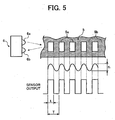
- the sensor 6 is a reflective type optical sensor including a light emitting element 6a and a light receiving element 6b.
- the light emitted from the light emitting element 6a toward the scale 5 is reflected, and is received by the light receiving element 6b.
- the amount of light reflected by the slit portions 5a that are the scale marks of the scale 5, and the amount of the light reflected by the rest part 5b of the scale 5 are detected differently.
- the senor 6 outputs two signals at high level (High) and low level (Low) based on a difference in reflectance between the slit portions 5a and the rest part 5b.
- the sensor 6 is such that the light receiving element 6b outputs a High signal in response to reception of the light, and that a reflectance of the slit portions 5a of the scale 5 is set higher than that of the rest part 5b. Then, during a time t, when the sensor 6 passes over the slit portion 5a, the sensor 6 outputs a High signal. Therefore, the sensor 6 repeatedly outputs High and Low, during rotation of the intermediate transfer belt 10, based on whether the slit portion 5a passes through a detection range of the sensor 6 as shown in Fig. 5 .
- a moving speed (belt speed) of the surface of the intermediate transfer belt 10 can be detected.
- this method is one of examples of detecting a belt speed of the intermediate transfer belt 10. Therefore, any sensor, any scale, and any method may be used if the belt speed can be detected by detecting a scale formed on the intermediate transfer belt 10.
- the microcomputer of the control device 70 as shown in Fig. 1 starts the process of ordinary belt speed correction for the intermediate transfer belt 10 at a predetermined timing.
- step 1 the belt drive motor 7 is turned on to rotate the belt drive motor 7 at a basic speed that is a target speed (which is controlled by the motor controller 73 as shown in Fig. 3 ), and the process proceeds to step 2.
- step 2 it is determined whether an OFF signal for turning off the belt drive motor 7 has been received. If it is determined that the OFF signal has been received (Yes at step 2), the process proceeds to step 3 where the belt drive motor 7 is turned off, and the process ends.
- step 4 If the OFF signal has not been received at step 2 and the process proceeds to step 4, a feedback signal is received from the sensor 6, and an actual speed V' of the surface of the intermediate transfer belt 10 is detected from the information. At step 5, the basic speed V and the actual speed V' are compared with each other.
- step 2 The determinations and processes at step 2 and thereafter are repeated, and correction is performed so that the actual speed V' is brought to the basic speed V. If it is determined at step 2 that the OFF signal that turns off the belt drive motor 7 has been received, the process proceeds to step 3 where the belt drive motor 7 is turned off, and the process ends.
- the scale 5 on the intermediate transfer belt 10 may be provided on the internal side of the belt or may be provided on the external side thereof. As explained in the embodiment of the present invention, there are some advantages in the case where the scale 5 is provided on the internal side of the belt. That is, soiling of the scale 5 or deposition of foreign matter on the scale 5 is difficult. Furthermore, scratching of the scale 5 is difficult, and because the sensor 6 that reads the scale 5 is also provided on the internal side of the belt, the sensor 6 also is not soiled.
- the scale 5 is provided on the internal side of the belt. That is, the sensor 6 of a large size cannot be used, a direction in which the sensor is provided is restricted, and a distance between the sensor and the belt is restricted.
- the scale 5 is provided on the external side of the belt. That is, the sensor 6 that reads the scale 5 is less restricted to its arrangement. However, there are some disadvantages such that the scale 5 may be soiled easily, foreign matter may be deposited on the scale 5 easily, and the scale 5 is easier to be scratched.
- the scale 5 is provided on the internal side of the intermediate transfer belt 10 as shown in Fig. 1 .
- the slit portion 5a may be finely scratched or may be deposited with foreign matter such as toner as time passes, which causes the reflectance of the reflective surface to degrade. If the reflectance is degraded, a pulse frequency output by the sensor 6 when detecting the slit portion 5a becomes abnormal.
- the frequency of pulse signals output from the sensor 6 when reading the scale 5 becomes constant. In other words, the count value of the pulse signals that are counted within the preset specified time becomes constant.
- the motor controller 73 of the control device 70 as shown in Fig. 3 cannot drive the belt drive motor 7 at a constant speed because the motor controller 73 controls the belt drive motor 7 based on the binary pulse signals.
- the intermediate transfer belt 10 cannot be corrected to an accurate belt speed, thereby causing color misalignment or the like to occur when a color image is formed.
- the belt device 20 and the color copying machine with the same include the motor controller 73 that functions as the scale-mark degradation determining unit, which determines how the slit portion 5a (see Fig. 4 and Fig. 5 ) is degraded. If the scale-mark degradation determining unit determines the degradation, the control device 70, which functions as the belt drive controller, continues the belt speed correction for the degraded portion such that the belt speed is controlled to the preset basic speed until the scale-mark degradation determining unit determines that there is no degradation of the slit portion 5a.
- the control device 70 which functions as the belt drive controller
- the belt speed correction for the degraded portion is the same as the seal correction that is performed on a seal 8 ( Fig. 4 ) of the scale 5.
- the belt device 20 and the color copying machine including the same perform the belt speed correction for the degraded portion. Therefore, even if the scale 5 is degraded by a scratch on a part of the scale 5 or by deposition of foreign matter such as a lump of toner thereon, the belt device 20 and the color copying machine can drive the belt drive motor 7 at the constant speed to accurately correct the belt speed of the intermediate transfer belt 10 so that color misalignment does not occur in the color image.
- the RAM of the motor controller 73 as shown in Fig. 3 stores the degradation-detecting reference pulse for the scale 5 as factory default setting. Therefore, the degradation-detecting reference pulse is output at any time when the belt device is driven. As shown in Fig. 9 , the degradation-detecting reference pulse is set so that a number of reference pulses are output within one pulse of a sensor output signal that is output when the sensor 6 detects the slit portion 5a.
- the number of degradation-detecting reference pulses that is output during one period T of the sensor output as shown in Fig. 9 is drawn strictly as an image, and therefore, the number can be changed if necessary.
- the motor controller 73 When the intermediate transfer belt 10 is made to rotate, the motor controller 73 repeatedly counts the degradation-detecting reference pulse up to the number N of reference pulses during a time corresponding to each period T (Tn). In other words, the motor controller 73 starts counting the degradation-detecting reference pulses at a time t 1 as shown in Fig. 9 , and receives a High sensor output signal S 2 on its rising edge at a timing of time t 2 .
- the time t 2 indicates a time at which the number of degradation-detecting reference pulses counted reaches the number N of reference pulses if there is neither a scratch nor a lump of toner on the slit portions 5a through rotation of the intermediate transfer belt 10 at a normal belt speed.
- the belt device 20 determines that the slit portion 5a is not degraded, i.e., is in a normal state, and controls the speed to the ordinary belt speed V 1 without performance of the seal correction that is the belt speed correction for a degraded portion during the next period T 1 .
- the motor controller 73 cannot detect the rising edge of a sensor signal S 3 at a timing of the time t 3 . Therefore, in this case, the belt device 20 determines that the slit portion 5a is degraded, and performs the belt speed correction (seal correction) for the degraded portion during the next period T 3 to control the belt speed to the basic speed V.
- the motor controller 73 detects the rising edge of a sensor signal S 4 at a delayed timing of a time t 6 ', instead of at a timing of the time t 6 .
- the time t 6 indicates a time at which the number of degradation-detecting reference pulses, the counting of which started at the time t 5 , reaches the number N of reference pulses. Therefore, the belt device 20 determines that the slit portion 5a is degraded, and performs the belt speed correction for the degraded portion during the next period T 5 to control the belt speed to the basic speed V.
- the motor controller 73 detects the rising edge of a sensor signal S 5 at a time t 7 '.
- the time t 7 ' indicates a time before the number of degradation-detecting reference pulses, the counting of which started at the time t 7 , reaches the number N of the reference pulses. Therefore, in this case also, the belt device 20 determines that the slit portion 5a has a small degraded portion, and performs the belt speed correction for the degraded portion during the next period T 8 to control the belt speed to the basic speed V.
- the belt speed control method in the belt device 20 includes steps explained below. That is, the method includes performing the ordinary belt speed correction in which an actual belt speed of the intermediate transfer belt 10 is detected from information for the scale 5 read by the sensor 6 to correct the belt speed based on the actual belt speed detected. Further, when the scale-mark degradation determining unit determines the degradation of the slit portion 5a, the belt speed correction for a degraded portion is performed such that the intermediate transfer belt 10 is made to rotate at the preset basic speed and the process of correction is continued until the scale-mark degradation determining unit determines that there is no degradation. Therefore, even if the slit portion 5a is degraded, the belt speed of the intermediate transfer belt 10 can be accurately controlled.
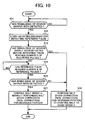
- Fig. 10 is a flowchart of the process procedure of belt speed correction for the degraded portion.
- step 11 it is determined whether the rising edge of a binary sensor output of the sensor 6 has been detected. If the rising edge has been detected (Yes at step 11), then at step 12, counting of the degradation-detecting reference pulse starts. If the rising edge has not been detected (No at step 11), the process returns to "start”. At step 13, it is determined whether the rising edge of the sensor output has been detected before the number of the degradation-detecting reference pulses reaches the number N of reference pulses.
- step 13 If the rising edge has been detected (Yes at step 13), the process proceeds to step 14 where the belt speed correction for a degraded portion is performed to control the belt speed of the intermediate transfer belt 10 to the basic speed V.
- step 15 it is determined whether the number of degradation-detecting reference pulses has reached the number N of reference pulses. At step 15, if the count has not reached the number N of reference pulses (No at step 15), the step 15 is repeated.
- step 16 it is determined whether has been detected. If the rising edge of the sensor output has not been detected (No at step 16), the process proceeds to step 14 where the belt speed correction for the degraded portion is performed to control the belt speed of the intermediate transfer belt 10 to the basic speed V. If the rising edge of the sensor output has been detected (Yes at step 16), the process proceeds to step 17 where the belt speed is controlled to the belt speed V 1 without performing the belt speed correction for the degraded portion, and the process ends.
- the number N of reference pulses as shown in Fig. 9 needs to be set to a value having an allowance like N- ⁇ to N+ ⁇ , where ⁇ is a value determined by considering fluctuations or the like. If the allowance is not provided, the detection of the rising edge of the output of the sensor 6 may fail due to fluctuations in the slit portions 5a, even if there is neither a scratch nor a lump of toner on the slit portion 5a, and the rising edge may be detected before the degradation-detecting reference pulse reaches the number N of reference pulses, which results in erroneous detection.
- the belt device detects the actual belt speed V' of the intermediate transfer belt 10 from the count of pulses output from the sensor 6, the pulses being counted within the preset specified time including an allowance wider than the time during which the degradation of the scale 5 is detected.
- the actual belt speed V' detected is compared with the basic speed as explained with reference to Fig. 6 to correct the belt speed, which allows the intermediate transfer belt 10 to be controlled to an accurate belt speed.
- how the slit portion 5a of the scale 5 is degraded is determined using the degradation-detecting reference pulses.
- how the slit portion 5a is degraded may be determined by comparing the frequency of a value output from the sensor 6 when reading the scale 5, with the preset reference frequency.
- the seal correction that is the belt speed correction for a degraded portion is also performed when the seal 8 as shown in Fig. 4 is detected.
- a current passing through the belt drive motor 7 is made equal to a current at which the belt speed becomes the basic speed V.
- a voltage to be applied to the belt drive motor 7 may be controlled, or a frequency may be controlled.
- control device 70 receives the pulses of the binary signal to correct the belt speed, determines that the belt speed is faster from an increase in the pulses in the portion containing the scratch SC, and controls the belt drive motor 7 to reduce the belt speed.
- the control device 70 determines that the belt speed is slower from a decrease in the pulse, contrary to the case of the small lump of toner or the small scratch, and controls the belt drive motor 7 so as to increase the belt speed, which results in unevenness in speed.
- the scratch or the like may be a small one present in one slit portion 5a, or may be a wide one that covers several slit portions 5a.
- the scale 5 formed along the intermediate transfer belt 10 has the seal 8.
- the space formed in this seal 8 is generally about 3 millimeters (mm) at maximum. Therefore, assuming that the belt speed (linear velocity) of the intermediate transfer belt 10 is 250 mm/s, the sensor 6 does not output a pulse signal at an interval of 12 milliseconds (ms) to detect the 3 mm-wide seal 8, when the intermediate transfer belt 10 is rotating.
- the specified number of pulses (reference frequency) in the image forming apparatus is 416 pulses.
- the specified number of pulses is output when the sensor 6 detects a normal scale 5 without degradation within a preset specified time (e.g., 1 ms) upon rotation of the intermediate transfer belt 10. For example, if the scale 5 has a scratch that spreads over 10 slit portions 5a, the pulse signals corresponding to the portion are not output, and therefore, the number of pulses within the specified time is 406 (416-10) that is less than 415. Therefore, the control device 70 performs seal correction for the portion with less number of pulses, i.e., degraded portion.
- the control device 70 determines that a large scratch or foreign matter having a length exceeding the space of the seal 8 is deposited on the scale 5, and stops the belt drive motor 7. This reduces a risk of an abnormal image output (e.g., color misalignment).
- the control device 70 causes a display portion 75 ( Fig. 1 ) that is visible on the outside of the device, to display a prompt indicating that the belt has stopped.
- control device 70 also functions as a belt-drive stop controller that stops the rotation of the intermediate transfer belt 10 when it is determined that the scale 5 is degraded by a predetermined value or more, if the time for execution of the seal correction exceeds 12 ms. Furthermore, the control device 70 also functions as a display unit that causes the display portion 75 to display a message when the belt-drive stop controller stops the rotation of the intermediate transfer belt 10.
- the timing at which the rotation of the intermediate transfer belt 10 is made to stop is preferably set to a time after the process of image formation in process, is complete. Alternatively, the stopping may be performed after formation of all images requested is complete.
- the display portion 75 also includes a display for informing belt replacement and a display for informing that the belt is soiled.
- control device 70 performs the seal correction (belt speed correction for the degraded portion).
- the color copying machine stores the number of times of performing the seal correction (the number of times of detecting degraded portions each having 417 pulses or more) to cause the display portion 75 to display an alarm when the number of times reaches the specified number or more.
- This control is also performed by the control device 70.
- the specified number of times is the number to be preset, and is determined through experiments.
- this belt-speed control system includes an encoder 65 that detects the number of revolutions of the rotating shaft of the belt drive motor 7. Moreover, a belt-speed-control switching unit is provided. The belt-speed-control switching unit switches to a control for the belt speed that is performed by the belt-speed control system, and controls the number of revolutions of the belt drive motor 7, when the scale-mark degradation determining unit determines the degradation of the predetermined value or more, by making the rotation of the intermediate transfer belt 10 continue.
- the belt-speed-control switching unit function is performed by a control unit 70' that includes a microcomputer, in the same manner as by the control device 70 as explained with reference to Fig. 1 .
- the degradation of the predetermined value or more indicates a case where a scratch or dirt wider than the seal 8 of Fig. 4 in the direction of belt movement is formed in the slit portion 5a, or a case where a large number of fine stains are deposited in the slit portion 5a. Even in such cases, by providing the belt-speed control system using the encoder 65 and the belt-speed-control switching unit, it is possible to continue rotation of the intermediate transfer belt 10. Consequently, there is no interruption in the image forming process.
- the image forming operation is complete after the intermediate transfer belt 10 is cleaned each time one image formation job is complete, and the belt speed control by the belt-speed control system using the encoder 65 is reset. If any stain has not been removed yet from the slit portion 5a upon starting the next image formation job, the control is switched again to the belt speed control by the belt-speed control system using the encoder 65. If the number of times of switching to the belt speed control using the encoder 65 reaches the predetermined number or more, the display portion 75 is made to display a message to replace the intermediate transfer belt 10.
- a method of detecting degradation of the scale is explained below. This method uses any measure other than the number of reference pulses and the frequency as explained with reference to Fig. 9 .
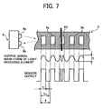
- the sensor 6 detects a slit portion 5a of the scale 5 and outputs pulses to determine how the scale 5 is degraded based on a period T of the pulses.
- a period T of the pulses In other words, how the period T as shown in Fig. 7 fluctuates due to a fluctuation in load to the intermediate transfer belt 10, is previously measured.
- a threshold value of the period is set to determine the degradation of the scale 5 from the result of measurement, and the threshold value is stored in the motor controller 73 ( Fig. 3 ) of the control device 70.
- the threshold value to determine degradation of the scale 5 is specified as T x (1 ⁇ 5/100), and this threshold value is stored in the motor controller 73.
- the fluctuation in load mentioned here indicates a fluctuation in load applied to the belt speed by equipment such as a roller in direct contact with the intermediate transfer belt 10.
- the control device 70 performs the seal correction to drive the belt drive motor 7 so that the belt speed is controlled to a basic speed.
- the occurrence period of pulses does not become equal to or less than the threshold value. Furthermore, if the load to the intermediate transfer belt 10 does not fluctuate, the occurrence period of pulses is T and becomes constant. In this case, the seal correction is not performed.
- the number of times of the seal correction is performed is stored.
- the display portion 75 is made to display an alarm in the same manner as explained above.
- the scale-mark degradation determining unit detects the degradation to correct the belt speed and to obtain an accurate belt speed. Therefore, even if the scale is slightly degraded, it is possible to keep the belt speed stable and accurate.
Landscapes
- Physics & Mathematics (AREA)
- General Physics & Mathematics (AREA)
- Electrostatic Charge, Transfer And Separation In Electrography (AREA)
Claims (10)
- Bandvorrichtung, umfassend:ein endlos bewegliches Band (10) mit einer Skala (5), die darauf entlang eines Umfangs gebildet ist, wobei die Skala (5) eine Vielzahl von Markierungen umfasst;einen ersten Sensor (6, 70), der eine erste Geschwindigkeit des Bands (10) basierend auf der Erfassung der Markierungen erfasst;einen Motor (7), der konfiguriert ist, um das Band (10) anzutreiben; undeine erste Bandgeschwindigkeits-Kontrolleinheit (70), die eine Geschwindigkeit des Bands (10) basierend auf der Differenz zwischen der ersten Geschwindigkeit und einer vorbestimmten Referenzgeschwindigkeit kontrolliert, dadurch gekennzeichnet, dass die Vorrichtung weiter Folgendes umfasst:einen zweiten Sensor (65, 70'), der eine zweite Geschwindigkeit des Bands (10) basierend auf einem Verfahren, das verschieden von der Erfassung der Markierungen ist, erfasst;eine zweite Bandgeschwindigkeits-Kontrolleinheit (70'), die eine Geschwindigkeit des Bands (10) basierend auf der Differenz zwischen der zweiten Geschwindigkeit und der vorbestimmten Referenzgeschwindigkeit kontrolliert;eine Einheit zur Bestimmung der Beschädigung der Skalierungsmarkierung (73), die basierend auf dem Signal vom Sensor (6) bestimmt, ob eine Beschädigung der Qualität der Markierungen aufgrund der Tatsache, dass die Markierungen verschlissen, beschädigt oder verschmutzt sind, vorliegt, und eine Höhe der Beschädigung nach der Bestimmung, dass eine Beschädigung der Qualität der Markierungen vorliegt, basierend auf einem Vergleich des Signals vom Sensor (6) mit einem vorbestimmten Schwellwert erfasst; undeine Bandantriebskontrolle (73), die verursacht, dass die erste Bandgeschwindigkeits-Kontrolleinheit (70) eine Geschwindigkeit des Bands (10) kontrolliert, wenn die Höhe der Beschädigung, die von der Einheit zur Bestimmung der Beschädigung der Skalierungsmarkierung (73) erfasst wird, geringer als ein vorbestimmter Wert ist, und verursacht, dass die zweite Bandgeschwindigkeits-Kontrolleinheit (70') eine Geschwindigkeit des Bands (10) kontrolliert, wenn die Höhe der Beschädigung, die von der Einheit zur Bestimmung der Beschädigung der Skalierungsmarkierung (73) erfasst wird, nicht geringer als der vorbestimmte Wert ist.
- Bandvorrichtung nach Anspruch 1, wobei
der erste Sensor (6, 70) ein Markierungserfassungssignal ausgibt, wenn er eine Markierung erfasst, und
die Einheit zur Bestimmung der Beschädigung der Skalierungsmarkierung (73) Impulse zählt und bestimmt, dass eine Beschädigung der Qualität der Markierungen vorliegt, wenn ein Markierungserfassungssignal nicht vom ersten Sensor (6, 70) ausgegeben wird, wenn die Einheit zur Bestimmung der Beschädigung der Skalierungsmarkierung (73) eine vorbestimmte Anzahl von Impulsen zählt, oder wenn ein Signal, das ähnlich dem Markierungserfassungssignal ist, ausgegeben wird, bevor die Einheit zur Bestimmung der Beschädigung der Skalierungsmarkierung (73) eine vorbestimmte Anzahl von Impulsen zählt. - Bandvorrichtung nach Anspruch 1, wobei der erste Sensor (6, 70) ein Markierungserfassungssignal mit einer spezifischen Frequenz ausgibt, wenn eine Markierung erfasst wird, und
die Einheit zur Bestimmung der Beschädigung der Skalierungsmarkierung (73) bestimmt, dass eine Beschädigung der Qualität der Markierungen vorliegt, wenn ein Markierungserfassungssignal mit einer Frequenz, die verschieden von einer vorbestimmten Frequenz ist, vom ersten Sensor (6, 70) ausgegeben wird. - Bandvorrichtung nach Anspruch 1, weiter umfassend:eine Bandantriebs-Stoppkontrolle (70), die die Drehung des Bandes (10) stoppt, wenn die Höhe der Beschädigung, die von der Einheit zur Bestimmung der Beschädigung der Skalierungsmarkierung (73) berechnet wird, nicht geringer als ein vorbestimmter Wert ist.
- Bandvorrichtung nach Anspruch 1, wobei der zweite Sensor (65, 70') ein Codierer (65) ist, der an eine Welle des Motors befestigt ist, der das Band (10) antreibt, und der die zweite Geschwindigkeit erfasst, indem er die Drehgeschwindigkeit der Welle erfasst.
- Bandvorrichtung nach Anspruch 1, weiter umfassend:einen Zähler, der die Anzahl von Malen zählt, die die Kontrolle der Geschwindigkeit von der zweiten Bandgeschwindigkeitskontrolleinheit (70') durchgeführt wird; undeine Anzeigeeinheit (75), die einen Alarm anzeigt, wenn die Anzahl, die vom Zähler gezählt wird, eine vorbestimmte Anzahl übersteigt.
- Bandvorrichtung nach Anspruch 4, weiter umfassend:eine Anzeigeeinheit (75), die einen Alarm anzeigt, wenn die Bandantriebs-Stoppkontrolle (70) die Drehung des Bandes (10) stoppt.
- Bandvorrichtung nach Anspruch 1, wobei die Steuervorrichtung (70) konfiguriert ist, um zu bestimmen, ob ein Motor-Aus-Signal empfangen wurde und den Motor (7) auszuschalten, wenn ein Motor-Aus-Signal empfangen wurde.
- Bilderzeugungsgerät, umfassend:eine Bandvorrichtung (20) nach Anspruch 1;undeine Vielzahl von lichtempfindlichen Elementen (40Y, 40C, 40M, 40K), die individuell Tonerbilder mit verschiedenen Farben tragen, und die zum Drehen gebracht werden, wobeidie Tonerbilder mit den verschiedenen Farben, die auf den lichtempfindlichen Elementen (40Y, 40C, 40M, 40K) gebildet sind, sequenziell auf das Band (10) in einer überlagerten Weise übertragen werden.
- Verfahren zur Kontrolle einer Geschwindigkeit eines endlos beweglichen Bands, das von einem Motor angetrieben wird, wobei das Band mit einer Skala bereitgestellt ist, die darauf entlang eines Umfangs gebildet ist, wobei die Skala eine Vielzahl von Markierungen umfasst, umfassend:Erfassung einer ersten Geschwindigkeit des Bands, basierend auf der Erfassung der Markierungen;dadurch gekennzeichnet, dass das Verfahren weiter Folgendes umfasst:Erfassung einer zweiten Geschwindigkeit des Bands, basierend auf einem Verfahren, das verschieden von der Erfassung der Markierungen ist;Bestimmung, ob eine Beschädigung der Qualität der Markierungen vorliegt und Erfassung einer Höhe der Beschädigung nach der Bestimmung, dass eine Beschädigung der Qualität der Markierungen vorliegt, basierend auf der Erfassung der Markierungen, undKontrolle einer Geschwindigkeit des Bands basierend auf der Differenz zwischen der ersten Geschwindigkeit und einer vorbestimmten Referenzgeschwindigkeit, wenn die Höhe der Beschädigung, die bei der Bestimmung erfasst wird, geringer als ein vorbestimmter Wert ist, und Kontrolle einer Geschwindigkeit des Bands basierend auf der Differenz zwischen der zweiten Geschwindigkeit und der vorbestimmten Referenzgeschwindigkeit, wenn die Höhe der Beschädigung nicht geringer als der vorbestimmte Wert ist.
Applications Claiming Priority (2)
| Application Number | Priority Date | Filing Date | Title |
|---|---|---|---|
| JP2004137353A JP4477412B2 (ja) | 2003-07-29 | 2004-05-06 | ベルト装置とそれを備えた画像形成装置とベルト速度制御方法 |
| JP2004137353 | 2004-05-06 |
Publications (3)
| Publication Number | Publication Date |
|---|---|
| EP1594016A2 EP1594016A2 (de) | 2005-11-09 |
| EP1594016A3 EP1594016A3 (de) | 2011-03-02 |
| EP1594016B1 true EP1594016B1 (de) | 2015-02-25 |
Family
ID=34940892
Family Applications (1)
| Application Number | Title | Priority Date | Filing Date |
|---|---|---|---|
| EP20050252414 Ceased EP1594016B1 (de) | 2004-05-06 | 2005-04-18 | Band, Bilderzeugungsgerät , und Verfahren zur Bandgeschwindigkeitskontrolle |
Country Status (1)
| Country | Link |
|---|---|
| EP (1) | EP1594016B1 (de) |
Families Citing this family (1)
| Publication number | Priority date | Publication date | Assignee | Title |
|---|---|---|---|---|
| JP2018004787A (ja) * | 2016-06-29 | 2018-01-11 | 富士ゼロックス株式会社 | 画像形成装置 |
Family Cites Families (3)
| Publication number | Priority date | Publication date | Assignee | Title |
|---|---|---|---|---|
| JPH1124507A (ja) * | 1997-07-07 | 1999-01-29 | Ricoh Co Ltd | 画像形成装置 |
| US6842602B2 (en) * | 2002-03-22 | 2005-01-11 | Ricoh Company, Ltd. | Drive control device and image forming apparatus including the same |
| JP2004021236A (ja) * | 2002-06-20 | 2004-01-22 | Ricoh Co Ltd | 画像形成装置 |
-
2005
- 2005-04-18 EP EP20050252414 patent/EP1594016B1/de not_active Ceased
Also Published As
| Publication number | Publication date |
|---|---|
| EP1594016A2 (de) | 2005-11-09 |
| EP1594016A3 (de) | 2011-03-02 |
Similar Documents
| Publication | Publication Date | Title |
|---|---|---|
| US7228095B2 (en) | Transfer apparatus, image forming apparatus, and method of correcting moving speed of belt | |
| JP3527352B2 (ja) | カラ−画像形成装置 | |
| JP5256873B2 (ja) | 画像形成装置及び画像形成方法 | |
| US7664413B2 (en) | Image forming device including a toner pattern forming unit | |
| US8036582B2 (en) | Belt driving device and image forming apparatus | |
| EP1510881B1 (de) | Antriebseinheit für ein endloses Bewegungselement, Bilderzeugungsgerät, Antriebseinheit für ein lichtempfindliches Element und Verfahren eines Degradationsprozesses für das endlose Bewegungselement | |
| EP1517192B1 (de) | Farbbilderzeugungsvorrichtung | |
| EP0999479A2 (de) | Bilderzeugungsgerät | |
| JP4498216B2 (ja) | カラー画像形成装置およびその制御方法 | |
| JP7486049B2 (ja) | 画像形成装置 | |
| US7133630B2 (en) | Belt device, image forming apparatus, and method to control belt speed | |
| JP4576215B2 (ja) | ベルト速度制御装置、プログラム、画像形成装置及びベルト速度制御方法 | |
| US7865095B2 (en) | Image forming apparatus including distance detection unit | |
| JP4116475B2 (ja) | ベルト装置と感光体装置と画像形成装置 | |
| JP3919589B2 (ja) | ベルト蛇行補正装置及び画像形成装置 | |
| EP1594016B1 (de) | Band, Bilderzeugungsgerät , und Verfahren zur Bandgeschwindigkeitskontrolle | |
| JP4422771B2 (ja) | ベルト装置及び画像形成装置 | |
| JP4283053B2 (ja) | 画像形成装置 | |
| JP4422770B2 (ja) | ベルト装置及び画像形成装置 | |
| JP2007164086A (ja) | ベルト駆動装置とそれを備えた画像形成装置 | |
| JP5040239B2 (ja) | 画像形成装置 | |
| JP2008111928A (ja) | ベルト移動装置およびこれを用いた画像形成装置 | |
| JP2006010855A (ja) | 回転駆動制御装置、画像形成装置及び回転駆動制御方法 | |
| JP2008129057A (ja) | ベルト移動装置及び画像形成装置 | |
| JP4359160B2 (ja) | ベルト装置及び画像形成装置 |
Legal Events
| Date | Code | Title | Description |
|---|---|---|---|
| PUAI | Public reference made under article 153(3) epc to a published international application that has entered the european phase |
Free format text: ORIGINAL CODE: 0009012 |
|
| 17P | Request for examination filed |
Effective date: 20050506 |
|
| AK | Designated contracting states |
Kind code of ref document: A2 Designated state(s): AT BE BG CH CY CZ DE DK EE ES FI FR GB GR HU IE IS IT LI LT LU MC NL PL PT RO SE SI SK TR |
|
| AX | Request for extension of the european patent |
Extension state: AL BA HR LV MK YU |
|
| PUAL | Search report despatched |
Free format text: ORIGINAL CODE: 0009013 |
|
| AK | Designated contracting states |
Kind code of ref document: A3 Designated state(s): AT BE BG CH CY CZ DE DK EE ES FI FR GB GR HU IE IS IT LI LT LU MC NL PL PT RO SE SI SK TR |
|
| AX | Request for extension of the european patent |
Extension state: AL BA HR LV MK YU |
|
| 17Q | First examination report despatched |
Effective date: 20110310 |
|
| AKX | Designation fees paid |
Designated state(s): DE FR GB |
|
| GRAP | Despatch of communication of intention to grant a patent |
Free format text: ORIGINAL CODE: EPIDOSNIGR1 |
|
| INTG | Intention to grant announced |
Effective date: 20140916 |
|
| RIN1 | Information on inventor provided before grant (corrected) |
Inventor name: SAKAI, YOSHIHIRO |
|
| GRAS | Grant fee paid |
Free format text: ORIGINAL CODE: EPIDOSNIGR3 |
|
| GRAA | (expected) grant |
Free format text: ORIGINAL CODE: 0009210 |
|
| AK | Designated contracting states |
Kind code of ref document: B1 Designated state(s): DE FR GB |
|
| REG | Reference to a national code |
Ref country code: GB Ref legal event code: FG4D |
|
| REG | Reference to a national code |
Ref country code: DE Ref legal event code: R096 Ref document number: 602005045880 Country of ref document: DE Effective date: 20150409 |
|
| REG | Reference to a national code |
Ref country code: DE Ref legal event code: R097 Ref document number: 602005045880 Country of ref document: DE |
|
| PLBE | No opposition filed within time limit |
Free format text: ORIGINAL CODE: 0009261 |
|
| STAA | Information on the status of an ep patent application or granted ep patent |
Free format text: STATUS: NO OPPOSITION FILED WITHIN TIME LIMIT |
|
| 26N | No opposition filed |
Effective date: 20151126 |
|
| REG | Reference to a national code |
Ref country code: FR Ref legal event code: PLFP Year of fee payment: 12 |
|
| REG | Reference to a national code |
Ref country code: FR Ref legal event code: PLFP Year of fee payment: 13 |
|
| REG | Reference to a national code |
Ref country code: FR Ref legal event code: PLFP Year of fee payment: 14 |
|
| PGFP | Annual fee paid to national office [announced via postgrant information from national office to epo] |
Ref country code: GB Payment date: 20180321 Year of fee payment: 14 |
|
| PGFP | Annual fee paid to national office [announced via postgrant information from national office to epo] |
Ref country code: DE Payment date: 20180420 Year of fee payment: 14 |
|
| PGFP | Annual fee paid to national office [announced via postgrant information from national office to epo] |
Ref country code: FR Payment date: 20180420 Year of fee payment: 14 |
|
| REG | Reference to a national code |
Ref country code: DE Ref legal event code: R119 Ref document number: 602005045880 Country of ref document: DE |
|
| GBPC | Gb: european patent ceased through non-payment of renewal fee |
Effective date: 20190418 |
|
| PG25 | Lapsed in a contracting state [announced via postgrant information from national office to epo] |
Ref country code: DE Free format text: LAPSE BECAUSE OF NON-PAYMENT OF DUE FEES Effective date: 20191101 Ref country code: GB Free format text: LAPSE BECAUSE OF NON-PAYMENT OF DUE FEES Effective date: 20190418 |
|
| PG25 | Lapsed in a contracting state [announced via postgrant information from national office to epo] |
Ref country code: FR Free format text: LAPSE BECAUSE OF NON-PAYMENT OF DUE FEES Effective date: 20190430 |