EP1593861A1 - Verbindungselement - Google Patents
Verbindungselement Download PDFInfo
- Publication number
- EP1593861A1 EP1593861A1 EP05009547A EP05009547A EP1593861A1 EP 1593861 A1 EP1593861 A1 EP 1593861A1 EP 05009547 A EP05009547 A EP 05009547A EP 05009547 A EP05009547 A EP 05009547A EP 1593861 A1 EP1593861 A1 EP 1593861A1
- Authority
- EP
- European Patent Office
- Prior art keywords
- housing
- element according
- tubular element
- tubular
- connecting element
- Prior art date
- Legal status (The legal status is an assumption and is not a legal conclusion. Google has not performed a legal analysis and makes no representation as to the accuracy of the status listed.)
- Granted
Links
- 230000001154 acute effect Effects 0.000 claims abstract description 3
- XAGFODPZIPBFFR-UHFFFAOYSA-N aluminium Chemical compound [Al] XAGFODPZIPBFFR-UHFFFAOYSA-N 0.000 claims description 2
- 229910052782 aluminium Inorganic materials 0.000 claims description 2
- 150000001875 compounds Chemical class 0.000 description 2
- 230000009286 beneficial effect Effects 0.000 description 1
- 230000001419 dependent effect Effects 0.000 description 1
- 238000001746 injection moulding Methods 0.000 description 1
- 238000003754 machining Methods 0.000 description 1
- 238000004519 manufacturing process Methods 0.000 description 1
- 239000000463 material Substances 0.000 description 1
- 230000000149 penetrating effect Effects 0.000 description 1
- 230000007704 transition Effects 0.000 description 1
Images

Classifications
-
- F—MECHANICAL ENGINEERING; LIGHTING; HEATING; WEAPONS; BLASTING
- F16—ENGINEERING ELEMENTS AND UNITS; GENERAL MEASURES FOR PRODUCING AND MAINTAINING EFFECTIVE FUNCTIONING OF MACHINES OR INSTALLATIONS; THERMAL INSULATION IN GENERAL
- F16B—DEVICES FOR FASTENING OR SECURING CONSTRUCTIONAL ELEMENTS OR MACHINE PARTS TOGETHER, e.g. NAILS, BOLTS, CIRCLIPS, CLAMPS, CLIPS OR WEDGES; JOINTS OR JOINTING
- F16B7/00—Connections of rods or tubes, e.g. of non-circular section, mutually, including resilient connections
- F16B7/18—Connections of rods or tubes, e.g. of non-circular section, mutually, including resilient connections using screw-thread elements
- F16B7/187—Connections of rods or tubes, e.g. of non-circular section, mutually, including resilient connections using screw-thread elements with sliding nuts or other additional connecting members for joining profiles provided with grooves or channels
Definitions
- the invention relates to an element for producing a detachable Connection of a tubular element with a profiled bar, wherein the tubular element has a longitudinal axis with at least one thereto parallel bore includes and the profile bar at least a flat longitudinal side with at least one undercut groove wherein one end of the tubular member is dull or in an acute angle impinges on a longitudinal side of the profile bar.
- Such compounds are often used Shelving systems for material supply, handrails or handles.
- the profile struts are a square profile with an undercut groove and a trained as a pipe Strut.
- the shaft of a hammer-shaped element is from a Sleeve taken, in turn, in a front side of the strut is plugged.
- the object of the invention is a To provide connecting element, which is simple and easy to assemble, without additional machining operations To make the profile elements to be connected.
- the object is achieved in that the Connecting element between the tubular element and the Profile bar is arranged.
- the element according to the invention is a homogeneous transition of the tubular element to the longitudinal side of the profiled bar guaranteed, since the outer contour of the connecting element in Substantially corresponds to the tubular element.
- Fig. 1 shows a T-shaped connection between a profile bar 10th and a tubular element 20.
- the Profile bar 10 as a stand and the tubular member 20 as Cross strut be formed.
- each side surface 11 of the Profilstabs10 On the side surfaces 11 of the Profilstabs10 are undercut grooves 12 arranged. In the example shown, each side surface has 11 a centrally extending groove 12.
- the tubular Element 20 a closed lateral surface and in the longitudinal direction extending hollow chambers 21, wherein a bore B as trained hollow chamber runs exactly on the longitudinal axis A.
- the inventive element 30 is between the profile bar 10 and arranged the tubular member 20, wherein the Outer diameter of the tubular and the connecting element in Are essentially the same size. This creates in this area no gradation, which is not only visually beneficial.
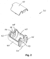
- Element 30 consists of a housing 40 and a cover 50.
- Bei plugged lid 50, the connecting element 30 has the shape a cylinder.
- the housing 40 of the element 30, which is preferably made of die-cast aluminum is manufactured, has a lateral surface and two, the Lateral surface limiting cylindrical surfaces 41, 42.
- the lateral surface is broken at one point. This breakthrough 47 allows unimpeded access to the inside of the Housing 40 lying fasteners and is with the lid 50th closable.
- the cylindrical surfaces 41, 42 have bores 43, 44, which in Direction of the breakthrough 47 are open. In these holes 43, 44 are means for attaching the connecting element 30 to the Profile bar 10 and received on the tubular element 20.
- the lid 50 preferably made of plastic injection molding adds the missing through the breakthrough 47 shell part surface of the Housing 40 when he with his locking means 51 (see Fig. 3) in complementarily formed counter-locking means 48 of the housing 40th is anchored.
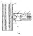
- FIG. 3 shows the connecting element 30 in built-in condition.
- the housing 40 is screwed over the screw S screwed into the bore B. firmly connected to the tubular element 20.
- the attachment of the housing 40 takes place at the first tubular element 20 by means of the screw S.
- the breakthrough 47 turns out to be open 44th configured recess of advantage by the shaft of the Hammer bolt H with the nut M on it orthogonal can be introduced to the longitudinal axis A in the housing.
- the lid 50 is attached to the housing 40.
- profile bars 10 the plurality of longitudinal grooves 12 on a side surface 11, the location and number of the end holes 44 adjusted accordingly.
Landscapes
- Engineering & Computer Science (AREA)
- General Engineering & Computer Science (AREA)
- Mechanical Engineering (AREA)
- Mutual Connection Of Rods And Tubes (AREA)
Abstract
Description
- Fig.1:
- eine perspektivische Ansicht einer Verbindung mit dem erfindungsgemäßen Element
- Fig. 2:
- eine perspektivische Explosionsdarstellung des Verbindungselements
- Fig. 3:
- eine Seitenansicht der Verbindung im Schnitt
Claims (8)
- Element zur Herstellung einer lösbaren Verbindung eines rohrförmigen Elements (20) mit einem Profilstab (10),
wobei das rohrförmige Element (20) eine Längsachse (A) mit mindestens einer dazu parallel verlaufenden Bohrung (B) umfasst und der Profilstab (10) mindestens eine ebene Längsseite (11) mit mindestens einer hinterschnittenen Nut (12) aufweist,
wobei ein Ende des rohrförmigen Elements stumpf oder in einem spitzen Winkel auf eine Längsseite des Profilstabs auftrifft,
dadurch gekennzeichnet, dass das Verbindungselement (30) zwischen dem rohrförmigen Element (20) und dem Profilstab (10) angeordnet ist. - Element nach Anspruch 1, dadurch gekennzeichnet, dass das Verbindungselement (30) zylindrisch ausgebildet ist und dessen Außenkontur im Wesentlichen der des rohrförmigen Elements (20) entspricht.
- Element nach Anspruch 2, dadurch gekennzeichnet, dass das Verbindungselement (30) aus einem Gehäuse (40) und einen Deckel (50) besteht.
- Element nach Anspruch 2, dadurch gekennzeichnet, dass das Gehäuse (40) zwei, stirnseitig die Mantelfläche begrenzende Zylinderflächen (41, 42) aufweist, in denen mindestens je eine Bohrung (43, 44) angeordnet ist.
- Element nach Anspruch 4, dadurch gekennzeichnet, dass die Zylinderflächen (41, 42) nach außen gerichtete Vorsprünge (45, 46) aufweisen.
- Element nach Anspruch 3, dadurch gekennzeichnet, dass die Mantelfläche des Gehäuses (40) einen Durchbruch (47) aufweist, der mit einem Deckel (50) verschließbar ist.
- Element nach Anspruch 4, dadurch gekennzeichnet, dass die mindestens eine Bohrung (43, 44) als eine zum Durchbruch (47) hin offene Ausnehmung ausgebildet ist.
- Element nach Anspruch 3, dadurch gekennzeichnet, dass das Gehäuse (40) aus Aluminium-Druckguss hergestellt ist.
Applications Claiming Priority (2)
| Application Number | Priority Date | Filing Date | Title |
|---|---|---|---|
| DE102004022471 | 2004-05-06 | ||
| DE102004022471A DE102004022471A1 (de) | 2004-05-06 | 2004-05-06 | Verbindungselement |
Publications (2)
| Publication Number | Publication Date |
|---|---|
| EP1593861A1 true EP1593861A1 (de) | 2005-11-09 |
| EP1593861B1 EP1593861B1 (de) | 2007-04-18 |
Family
ID=34936017
Family Applications (1)
| Application Number | Title | Priority Date | Filing Date |
|---|---|---|---|
| EP05009547A Expired - Lifetime EP1593861B1 (de) | 2004-05-06 | 2005-04-30 | Verbindungselement |
Country Status (3)
| Country | Link |
|---|---|
| EP (1) | EP1593861B1 (de) |
| DE (2) | DE102004022471A1 (de) |
| ES (1) | ES2287837T3 (de) |
Cited By (2)
| Publication number | Priority date | Publication date | Assignee | Title |
|---|---|---|---|---|
| FR2974397A1 (fr) * | 2011-04-20 | 2012-10-26 | Trilogiq Sa | Piece de raccordement pour moyen de liaison pour poste de travail comprenant un ensemble de transfert lineaire de pieces. |
| EP2944832A1 (de) * | 2014-04-23 | 2015-11-18 | Alusic S.r.l. | Montagesystem für abschnitte |
Families Citing this family (1)
| Publication number | Priority date | Publication date | Assignee | Title |
|---|---|---|---|---|
| US10662650B2 (en) | 2017-10-31 | 2020-05-26 | Vention Inc. | T-slot extrusion structure |
Citations (4)
| Publication number | Priority date | Publication date | Assignee | Title |
|---|---|---|---|---|
| DE2232788A1 (de) * | 1971-07-07 | 1973-01-18 | Georges Julien Condevaux | Verbindungselement |
| DE29514815U1 (de) * | 1995-09-14 | 1995-11-23 | Alusett-System GmbH, 85764 Oberschleißheim | Verbindungselement zum Verbinden zweier Stangenprofile |
| DE29508686U1 (de) * | 1995-05-24 | 1996-09-26 | Klafs Saunabau GmbH & Co Medizinische Technik, 74523 Schwäbisch Hall | Bausatz zum Erstellen von Umkleidekabinen, Trennwänden u.dgl. |
| WO2001004438A1 (de) * | 1999-07-13 | 2001-01-18 | Octanorm-Vertriebs-GmbH für Bauelemente | Tragprofil |
-
2004
- 2004-05-06 DE DE102004022471A patent/DE102004022471A1/de not_active Withdrawn
-
2005
- 2005-04-30 EP EP05009547A patent/EP1593861B1/de not_active Expired - Lifetime
- 2005-04-30 ES ES05009547T patent/ES2287837T3/es not_active Expired - Lifetime
- 2005-04-30 DE DE502005000598T patent/DE502005000598D1/de not_active Expired - Lifetime
Patent Citations (4)
| Publication number | Priority date | Publication date | Assignee | Title |
|---|---|---|---|---|
| DE2232788A1 (de) * | 1971-07-07 | 1973-01-18 | Georges Julien Condevaux | Verbindungselement |
| DE29508686U1 (de) * | 1995-05-24 | 1996-09-26 | Klafs Saunabau GmbH & Co Medizinische Technik, 74523 Schwäbisch Hall | Bausatz zum Erstellen von Umkleidekabinen, Trennwänden u.dgl. |
| DE29514815U1 (de) * | 1995-09-14 | 1995-11-23 | Alusett-System GmbH, 85764 Oberschleißheim | Verbindungselement zum Verbinden zweier Stangenprofile |
| WO2001004438A1 (de) * | 1999-07-13 | 2001-01-18 | Octanorm-Vertriebs-GmbH für Bauelemente | Tragprofil |
Cited By (2)
| Publication number | Priority date | Publication date | Assignee | Title |
|---|---|---|---|---|
| FR2974397A1 (fr) * | 2011-04-20 | 2012-10-26 | Trilogiq Sa | Piece de raccordement pour moyen de liaison pour poste de travail comprenant un ensemble de transfert lineaire de pieces. |
| EP2944832A1 (de) * | 2014-04-23 | 2015-11-18 | Alusic S.r.l. | Montagesystem für abschnitte |
Also Published As
| Publication number | Publication date |
|---|---|
| DE102004022471A1 (de) | 2005-12-01 |
| ES2287837T3 (es) | 2007-12-16 |
| EP1593861B1 (de) | 2007-04-18 |
| DE502005000598D1 (de) | 2007-05-31 |
Similar Documents
| Publication | Publication Date | Title |
|---|---|---|
| EP0875640A1 (de) | Vorrichtung zur Befestigung eines Handlaufelements an einem Pfosten, insbesondere zur Herstellung eines Treppengeländers, und Bausatz dafür | |
| DE102005057397A1 (de) | Mehrzweckprofile für den Zusammenbau von Rahmen, Haltevorrichtungen, tragenden Teilen und ähnlichem | |
| DE29924278U1 (de) | Radschützer für Zweiräder | |
| EP0501148B1 (de) | Verbindungssystem für zwei als Rohr- oder Stangen- und/oder Knotenelemente ausgebildete Bauteile | |
| DE69721868T2 (de) | Dachanordnung | |
| DE202013100325U1 (de) | Drückerlagerung eines Tür- oder Fensterdrückers | |
| EP1593861B1 (de) | Verbindungselement | |
| EP1464849B1 (de) | Höhenverstellbarer Standfuss | |
| DE2615322A1 (de) | Tuerschild bzw. tuerrosette | |
| DE9202868U1 (de) | Griffsystem | |
| DE2643354C2 (de) | Verbindungsbeschlag zum lösbaren Zusammenhalten von Möbelwandungen | |
| DD203089A5 (de) | Befestigungselement | |
| DE4420037B4 (de) | Verbindungselement insbesondere zur Montage von Türdrückern, Griffen od. dgl. an Türen, Fenstern od. dgl. | |
| DE69401294T2 (de) | Einrichtung zur Befestigung eines Schlosses in seinem Gehäuse | |
| DE10309087A1 (de) | Befestigungseinrichtung für Kraftfahrzeug-Scheinwerfer | |
| DE3324383A1 (de) | Vorrichtung zum befestigen eines schlauchs am handgriff einer brause | |
| EP0856617A2 (de) | Geländer | |
| DE3817271A1 (de) | Verbindungseinrichtung fuer die montage von ziergittern | |
| EP1081392A2 (de) | Verbindungsbeschlag zum Gegeneinanderspannen zweier Teile | |
| DE202007008397U1 (de) | Möbelsystem sowie Möbelstück | |
| DE102004037530B4 (de) | Verbindungselement | |
| DE9100854U1 (de) | Befestigungsvorrichtung | |
| DE3151982C2 (de) | ||
| DE10335113B4 (de) | Scharnier für stumpf anschlagende Türen | |
| DE102023112864A1 (de) | Beschlag für Türen oder Fenster |
Legal Events
| Date | Code | Title | Description |
|---|---|---|---|
| PUAI | Public reference made under article 153(3) epc to a published international application that has entered the european phase |
Free format text: ORIGINAL CODE: 0009012 |
|
| AK | Designated contracting states |
Kind code of ref document: A1 Designated state(s): AT BE BG CH CY CZ DE DK EE ES FI FR GB GR HU IE IS IT LI LT LU MC NL PL PT RO SE SI SK TR |
|
| AX | Request for extension of the european patent |
Extension state: AL BA HR LV MK YU |
|
| 17P | Request for examination filed |
Effective date: 20051212 |
|
| AKX | Designation fees paid |
Designated state(s): CH DE ES FR IT LI |
|
| GRAP | Despatch of communication of intention to grant a patent |
Free format text: ORIGINAL CODE: EPIDOSNIGR1 |
|
| GRAS | Grant fee paid |
Free format text: ORIGINAL CODE: EPIDOSNIGR3 |
|
| GRAA | (expected) grant |
Free format text: ORIGINAL CODE: 0009210 |
|
| AK | Designated contracting states |
Kind code of ref document: B1 Designated state(s): CH DE ES FR IT LI |
|
| REG | Reference to a national code |
Ref country code: CH Ref legal event code: EP |
|
| REF | Corresponds to: |
Ref document number: 502005000598 Country of ref document: DE Date of ref document: 20070531 Kind code of ref document: P |
|
| REG | Reference to a national code |
Ref country code: CH Ref legal event code: NV Representative=s name: SCINTILLA AG, DIREKTION |
|
| ET | Fr: translation filed | ||
| REG | Reference to a national code |
Ref country code: ES Ref legal event code: FG2A Ref document number: 2287837 Country of ref document: ES Kind code of ref document: T3 |
|
| PLBE | No opposition filed within time limit |
Free format text: ORIGINAL CODE: 0009261 |
|
| STAA | Information on the status of an ep patent application or granted ep patent |
Free format text: STATUS: NO OPPOSITION FILED WITHIN TIME LIMIT |
|
| 26N | No opposition filed |
Effective date: 20080121 |
|
| PGFP | Annual fee paid to national office [announced via postgrant information from national office to epo] |
Ref country code: CH Payment date: 20110421 Year of fee payment: 7 Ref country code: FR Payment date: 20110427 Year of fee payment: 7 Ref country code: ES Payment date: 20110419 Year of fee payment: 7 |
|
| PGFP | Annual fee paid to national office [announced via postgrant information from national office to epo] |
Ref country code: IT Payment date: 20110422 Year of fee payment: 7 |
|
| REG | Reference to a national code |
Ref country code: CH Ref legal event code: PL |
|
| REG | Reference to a national code |
Ref country code: FR Ref legal event code: ST Effective date: 20121228 |
|
| PG25 | Lapsed in a contracting state [announced via postgrant information from national office to epo] |
Ref country code: LI Free format text: LAPSE BECAUSE OF NON-PAYMENT OF DUE FEES Effective date: 20120430 Ref country code: CH Free format text: LAPSE BECAUSE OF NON-PAYMENT OF DUE FEES Effective date: 20120430 |
|
| PG25 | Lapsed in a contracting state [announced via postgrant information from national office to epo] |
Ref country code: FR Free format text: LAPSE BECAUSE OF NON-PAYMENT OF DUE FEES Effective date: 20120430 Ref country code: IT Free format text: LAPSE BECAUSE OF NON-PAYMENT OF DUE FEES Effective date: 20120430 |
|
| REG | Reference to a national code |
Ref country code: ES Ref legal event code: FD2A Effective date: 20130716 |
|
| PG25 | Lapsed in a contracting state [announced via postgrant information from national office to epo] |
Ref country code: ES Free format text: LAPSE BECAUSE OF NON-PAYMENT OF DUE FEES Effective date: 20120501 |
|
| PGFP | Annual fee paid to national office [announced via postgrant information from national office to epo] |
Ref country code: DE Payment date: 20210624 Year of fee payment: 17 |
|
| REG | Reference to a national code |
Ref country code: DE Ref legal event code: R119 Ref document number: 502005000598 Country of ref document: DE |
|
| PG25 | Lapsed in a contracting state [announced via postgrant information from national office to epo] |
Ref country code: DE Free format text: LAPSE BECAUSE OF NON-PAYMENT OF DUE FEES Effective date: 20221103 |