EP1593635A1 - Dispositif de pliage en parallèle dans une machine à pliage - Google Patents
Dispositif de pliage en parallèle dans une machine à pliage Download PDFInfo
- Publication number
- EP1593635A1 EP1593635A1 EP05008767A EP05008767A EP1593635A1 EP 1593635 A1 EP1593635 A1 EP 1593635A1 EP 05008767 A EP05008767 A EP 05008767A EP 05008767 A EP05008767 A EP 05008767A EP 1593635 A1 EP1593635 A1 EP 1593635A1
- Authority
- EP
- European Patent Office
- Prior art keywords
- cylinder
- guide
- jaw cylinder
- folding
- jaw
- Prior art date
- Legal status (The legal status is an assumption and is not a legal conclusion. Google has not performed a legal analysis and makes no representation as to the accuracy of the status listed.)
- Withdrawn
Links
Images


Classifications
-
- B—PERFORMING OPERATIONS; TRANSPORTING
- B65—CONVEYING; PACKING; STORING; HANDLING THIN OR FILAMENTARY MATERIAL
- B65H—HANDLING THIN OR FILAMENTARY MATERIAL, e.g. SHEETS, WEBS, CABLES
- B65H45/00—Folding thin material
- B65H45/12—Folding articles or webs with application of pressure to define or form crease lines
- B65H45/16—Rotary folders
- B65H45/162—Rotary folders with folding jaw cylinders
- B65H45/167—Rotary folders with folding jaw cylinders having associated sheet guide means
-
- B—PERFORMING OPERATIONS; TRANSPORTING
- B65—CONVEYING; PACKING; STORING; HANDLING THIN OR FILAMENTARY MATERIAL
- B65H—HANDLING THIN OR FILAMENTARY MATERIAL, e.g. SHEETS, WEBS, CABLES
- B65H29/00—Delivering or advancing articles from machines; Advancing articles to or into piles
- B65H29/52—Stationary guides or smoothers
-
- B—PERFORMING OPERATIONS; TRANSPORTING
- B65—CONVEYING; PACKING; STORING; HANDLING THIN OR FILAMENTARY MATERIAL
- B65H—HANDLING THIN OR FILAMENTARY MATERIAL, e.g. SHEETS, WEBS, CABLES
- B65H2404/00—Parts for transporting or guiding the handled material
- B65H2404/60—Other elements in face contact with handled material
- B65H2404/69—Other means designated for special purpose
- B65H2404/693—Retractable guiding means, i.e. between guiding and non guiding position
Definitions
- This invention relates to a parallel folding apparatus of a folding machine, which can smoothly perform transfer of a signature between a first jaw cylinder and a second jaw cylinder during parallel folding.
- a web rotary printing press is equipped with a folding machine for cutting a web, which has been dried and cooled after printing, into predetermined lengths, and folding the cut web in a width direction or a lengthwise direction.
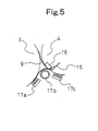
- the folding machine is available with various structures and, for example, is equipped with a parallel folding apparatus as shown in FIG. 4 or FIG. 5 (see Japanese Patent Application Laid-Open No. 2000-95431; hereinafter referred to as Patent Document 1).
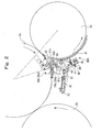
- the parallel folding apparatus has a cut-off cylinder 1, a folding cylinder 2, a first jaw cylinder 3, and a second jaw cylinder 4 opposed to one another in contact with one another and rotating in directions of arrows in FIG. 4.
- a web 8 which has been fed between nipping rollers 5 ⁇ cross perforation cylinders 6 ⁇ nipping rollers 7, is cut to predetermined dimensions by a cut-off knife (not shown) of the cut-off cylinder 1.
- the front end of the cut web is transported by a pin (not shown) of the folding cylinder 2, and then the cut web is parallel-folded between a single folding knife (not shown) of the folding cylinder 2 and a site between a gripper board 10 and a gripper jaw 11 of the first jaw cylinder 3 to form a signature 9.
- the signature 9 is transported, unchanged, toward a chopper 14 by a gripper 12 and a gripper pad 13 of the second jaw cylinder 4.
- the signature 9 is further parallel-folded between a double folding knife (not shown) of the first jaw cylinder 3 and a site between a gripper board 15 and a gripper jaw 16 of the second jaw cylinder 4 to form a double parallel fold.
- the so folded signature 9 is transported toward the chopper 14.
- 17a to 17c denote signature transport/holding brushes used in the transfer of the signature 9 between the first jaw cylinder 3 and the second jaw cylinder 4.
- a continuous guide plate 18 may conventionally be provided to provide along the circumferential surface of the first jaw cylinder 3 and the circumferential surface of the second jaw cylinder 4, as shown in FIG. 6.
- the front end of the signature 9 gripped between the gripper board 10 and the gripper jaw 11 (see FIG. 4) of the first jaw cylinder 3 is released at a predetermined time point (the time point before the folded portion of the signature 9 is gripped, for gripping change, between the double folding knife of the first jaw cylinder 3 and the site between the gripper board 15 and the gripper jaw 16 of the second jaw cylinder 4) after passing through the point of contact between the first jaw cylinder 3 and the second jaw cylinder 4.
- the following problem may occur at the time of release: That is, the front end of the signature 9 is not guided into a clearance between the guide plate 18 and the circumferential surface of the first jaw cylinder 3, but enters a space between the guide plate 18 and the circumferential surface of the second jaw cylinder 4. As a result, the trouble may occur that the signature 9 is folded up in a curled state, or dropped without being folded up, whereby a jam is caused.
- the front end of the signature 9 is not guided into the clearance between the guide plate 18 and the circumferential surface of the first jaw cylinder 3, but enters the space between the guide plate 18 and the second jaw cylinder 4, because of weak inertia. Consequently, the signature 9 is not guided by the guide plate and the circumferential surface of the first jaw cylinder.
- the front end of the signature 9 is positively guided into the clearance between the guide plate 18 and the circumferential surface of the first jaw cylinder 3 by means of inertia, so that there is no problem.
- the guide plate is located toward the site of contact between the first jaw cylinder and the second j aw cylinder, on the other hand, the front end of the signature 9 is guided by the guide plate during a low speed operation, but the trouble arises that the signature is rubbed by the guide plate during a high speed operation. Even in the case of the signature transport/holding brushes 17a to 17c, the brushes 17a to 17c wear and become unable to guide the signature, presenting the same problems as those caused by the guide plate 18.
- An object of the present invention is to provide a parallel folding apparatus of a folding machine, which can smoothly perform the transfer of a signature between first and second jaw cylinders during parallel folding, regardless of the operating speed of the folding machine.
- a parallel folding apparatus of a folding machine comprising a first cylinder and a second cylinder arranged, with circumferential surfaces of the first cylinder and the second cylinder being in contact with each other, further comprising a guide member for guiding a signature which is transported on a lower circumferential surface of the second cylinder after being parallel-folded by gripping/holding means of the second cylinder in cooperation with knives of the first cylinder, the guide member comprising a stationary guide which is located downstream, in a rotating direction, of a point of contact between the first cylinder and the second cylinder and disposed along the circumferential surface of the first cylinder and the circumferential surface of the second cylinder, and a moving guide which is disposed in such a manner as to be movable by drive means in accordance with an operating speed of the folding machine between a close position, where the moving guide is closer to the circumferential surface of the first cylinder and the circumferential surface of the second cylinder than the stationary
- the moving guide may have moving guide portions separated from one another by a predetermined spacing in an axial direction
- the stationary guide may have stationary guide portions separated from one another by a predetermined spacing in an axial direction
- the moving guide portions can advance and retreat through the spacings between the stationary guide portions.
- the second cylinder may be located below the first cylinder and may make contact with the first cylinder.
- the drive means may act to locate the moving guide at the close position when the operating speed of the folding machine is equal to or lower than a predetermined speed, and to locate the moving guide at the remote position when the operating speed of the folding machine exceeds the predetermined speed.
- the predetermined speed may be 200 rpm.
- the moving guide may be located at the close position when the signature is folded between the first cylinder and the second cylinder.
- the moving guide may be located at the remote position when the signature is not folded between the first cylinder and the second cylinder.
- the first cylinder may be a first jaw cylinder for forming a signature in cooperation with a folding cylinder
- the second cylinder may be a lower second jaw cylinder for folding the signature in cooperation with the first jaw cylinder or for receiving the signature from the first jaw cylinder without folding the signature.
- the parallel folding apparatus may further comprise an upper second jaw cylinder which is opposed to the first jaw cylinder on a side upstream, in a rotating direction of the first jaw cylinder, of an opposing position where the first j aw cylinder and the lower second jaw cylinder are opposed to each other, and on a side downstream, in the rotating direction of the first jaw cylinder, of an opposing position where the folding cylinder and the first jaw cylinder are opposed to each other.
- the stationary guide may have a first guide surface opposed to the first cylinder and having a curved portion separated by a predetermined distance from the circumferential surface of the first cylinder; a second guide surface opposed to the second cylinder and having a curved portion separated by a predetermined distance from the circumferential surface of the second cylinder; and a third guide surface which establishes communication between the first guide surface and the second guide surface in such a manner as to have a curved portion pointing toward a position where the first cylinder and the second cylinder are opposed to each other, and the moving guide may have a guide surface having a curved portion pointing toward the position where the first cylinder and the second cylinder are opposed to each other.
- the close position may be a position where the guide surface is closer than the third guide surface to the position where the first cylinder and the second cylinder are opposed to each other.
- a plurality of the moving guide portions may be supported with spacing by a support member, and the stationary guide may have a plurality of notches corresponding to the moving guide portions.
- the moving guide is moved to the position closer to the circumferential surface of the first jaw cylinder than the stationary guide.
- the front end of the signature gripped by the gripping/holding means of the first jaw cylinder is guided into the clearance between the moving guide and the circumferential surface of the first jaw cylinder at an early time point after passage through the point of contact between the first jaw cylinder and the second jaw cylinder.
- the moving guide is moved to the position more remote from the circumferential surface of the first jaw cylinder than the stationary guide.
- the front end of the signature is positively guided, as usual, by inertia into the clearance between the stationary guide and the circumferential surface of the first jaw cylinder, so that no problem is caused.
- the event that the moving guide is located excessively forward (keeps staying at the position close to the circumferential surface of the first jaw cylinder) , and its end portion on the side of the second jaw cylinder forms an edge, thereby rubbing the signature, can be avoided.
- the transfer of the signature between the first jaw cylinder and the second jaw cylinder in the case of parallel folding can be performed smoothly. Furthermore, the moving guide can be moved by the drive means, thus facilitating automation.
- FIG. 1 is a schematic side view of a folding machine of a rotary printing press, showing an embodiment of the present invention.
- FIG. 2 is an enlarged side view of essential parts of the folding machine.
- FIG. 3 is an enlarged plan view of the essential parts.
- a web W which has been cooled and dried after printing and then guided to an insert portion of a folding machine, is fed between a pair of nipping rollers 20 ⁇ a pair of cross perforation cylinders 21 ⁇ a pair of nipping rollers 22.
- This web W is then transported to a parallel folding apparatus 23 for cutting the web to predetermined dimensions and folding the cut web.
- the parallel folding apparatus 23 is equipped with a cut-off cylinder 24, a folding cylinder 25, a first jaw cylinder 26, and upper and lower second jaw cylinders 27, 28, each cylinder rotating in a direction indicated by an arrow in FIG. 1.
- the web W fed between the cut-off cylinder 24 and the folding cylinder 25 is cut to predetermined dimensions by a cut-off knife (not shown) of the cut-off cylinder 24, and held by a pin (not shown) of the folding cylinder 25 to be wrapped round the lower circumferential surface of the folding cylinder 25.
- the cut web held by the pin is then gripped by gripper boards 29a to 29d of the first jaw cylinder 26 (the gripper boards 29a to 29d are gripping/holding means provided in large numbers in the axial direction of gripper board shafts 30a to 30d disposed at positions dividing the peripheral surface of the first jaw cylinder 26 into four equal parts) while being half-folded by a knife (not shown) of the folding cylinder 25 acting in cooperation with the gripper boards 29a to 29d.
- Knives 64a to 64d are provided in large numbers in the axial direction of knife shafts 65a to 65d disposed at positions dividing the peripheral surface of the first jaw cylinder 26 into four equal parts.
- the aforementioned upper second jaw cylinder 27 and the lower second jaw cylinder (second cylinder) 28 are provided in contact with the first jaw cylinder 26.
- an upper transport belt group 31A comprising upper and lower paired transport belts
- an upper chopper folding apparatus 32A located toward a front portion of the upper transport belt group 31A.
- a lower transport belt group 31B comprising upper and lower paired transport belts
- a lower chopper folding apparatus 32B located toward a rear portion of the lower transport belt group 31B.
- Downstream of the upper transport belt group 31A there are provided a fan wheel 33 and a conveyor 34 for delivery.
- the first jaw cylinder 26, the upper second jaw cylinder 27, and the lower second jaw cylinder 28 are connected together by a gear mechanism (not shown) so that they rotate at predetermined rotational speeds.
- grippers 36a to 36d are provided in the axial direction of gripper shafts 35a to 35d disposed at positions dividing the peripheral surface of the upper second jaw cylinder 27 into four equal parts.
- many gripper boards (gripping/holding means) 66a to 66d are provided in the axial direction of gripper board shafts 67a to 67d.
- many gripper devices (gripping/holding means, hereinafter referred to as grippers) 38b, 38d are provided in the axial direction of gripper shafts 37b, 37d disposed at positions dividing the peripheral surface of the lower second jaw cylinder 28 into two equal parts.
- gripper boards (gripping/holding means) 68b, 68d are provided in the axial direction of gripper board shafts 69b, 69d.
- the grippers 36a to 36d of the upper second jaw cylinder 27 are sequentially brought into opposed relationship with the gripper boards 29a to 29d of the first jaw cylinder 26, while the grippers 38b, 38d of the lower second jaw cylinder 28 are brought into opposed relationship only with the gripper boards 29b, 29d of the first jaw cylinder 26.
- a cam mechanism (not shown; switching means) is provided in the first jaw cylinder 26 to switch the route of transport by performing the following so-called upward merger delivery or so-called up-and-down allocation delivery:
- the upward merger delivery is a procedure by which the signature transported, one signature at one time, is held by the first jaw cylinder 26 at the position of contact between the folding cylinder 25 and the first jaw cylinder 26 by actuating the gripper boards 29a to 29d at this position, and is then transferred from the gripper boards 29a to 29d of the first jaw cylinder 26 only to the grippers 36a to 36d of the upper second jaw cylinder 27.
- the up-and-down allocation delivery is a procedure by which the signature transported and held in theabove-mentioned manneristransferred alternately from the gripper boards 29a to 29d of the first jaw cylinder 26 to the grippers 36a, 36c of the upper second jaw cylinder 27, and from the gripper boards 29a to 29d of the first jaw cylinder 26 to the grippers 38b, 38d of the lower second jaw cylinder 28.
- the rotation phase (position) of gripper opening in the gripper boards 29a to 29d of the first jaw cylinder 26 is switched among three stages by the above cam mechanism, whereby the folding specifications for parallel folding can be changed to single folding, double folding and delta folding.
- the positional relation between the pin and the knife (not shown) can be adjusted by a double cylinder structure according to the above folding specifications.
- the grippers 36a to 36d and gripper boards 66a to 66d of the upper second jaw cylinder 27, and the grippers 38b, 38d and gripper boards (gripping/holding means) 68b, 68d of the lower second jaw cylinder 28 can be switched by cam mechanisms (not shown).
- gripping change is performed between the knives 64a to 64d of the first jaw cylinder 26 and the gripper boards 66a to 66d of the upper second jaw cylinder 27 and between the knives 64a to 64d of the first jaw cylinder 26 and the gripper boards 68b, 68d of the lower second jaw cylinder 28.
- the gripper boards 29a to 29d of the first jaw cylinder 26 make a gripper opening motion.
- Guide plates 40A, 40B, 40C of predetermined curved shapes, which guide the transport of the signature, are provided along the circumferential surface of the first jaw cylinder 26 at positions between the first jaw cylinder 26 and the respective cylinders.
- a stationary guide 41 which is located downstream of the point of contact between the first jaw cylinder 26 and the lower second jaw cylinder 28 in the direction of rotation and is disposed continuously along the circumferential surface of the first jaw cylinder and the circumferential surface of the lower second jaw cylinder; and a moving guide 43 disposed in such a manner as to be movable by an air cylinder (drive means) 42between a position approaching the circumferential surface of the first jaw cylinder with respect to the stationary guide 41 (see a solid-line position in FIG. 2) and a position separated from the circumferential surface of the first jaw cylinder with respect to the stationary guide 41 (see a chain-line position in FIG. 2) in accordance with the operating speed of the folding machine.
- the stationary guide 41 is fixed onto a stay bar 45, extending between frames 44 of the folding machine, via a fixing block 46 and a bracket 47.
- the bracket 47 has an initial position finely adjustable on the fixing block 46 via adjusting screws 48.
- the stationary guide 41 has a first guide surface 41a opposed to the first jaw cylinder 26 and having a curved portion separated by a predetermined distance from the circumferential surface of the first jaw cylinder 26; a second guide surface 41b opposed to the lower second jaw cylinder 28 and having a curved portion separated by a predetermined distance from the circumferential surface of the lower second jaw cylinder 28; and a third guide surface 41c which establishes communication between the first guide surface 41a and the second guide surface 41b in such a manner as to have a curved portion pointing toward a position where the first jaw cylinder 26 and the lower second jaw cylinder 28 are opposed to each other.
- the moving guide 43 comprises a plurality of strip-shaped plate portions (moving guide portions) 43a mounted with predetermined spacing onto a stay bar 49, which extends in the direction of paper width, by bolts 55 via mounting portions 43b.
- the strip-shaped plate portions 43a can move toward and away from the circumferential surface of the first jaw cylinder through a plurality of slits (notches) 41d which are formed, in correspondence with the plate portions 43a, in an end portion, beside the first jaw cylinder, of the stationary guide 41 comprising a single plate.
- An end portion, on the side of the point of contact between the first jaw cylinder 26 and the lower second jaw cylinder 28, of the plate portion 43a is greatly curved in a direction away from the circumferential surface of the first j aw cylinder so as to be able to guide the parallel-folded signature smoothly to the circumferential surface of the lower second jaw cylinder 28.
- the plate portion 43a of the moving guide 43 also has a guide surface 43c having a curved portion pointing toward the position where the first jaw cylinder 26 and the lower second jaw cylinder 28 are opposed to each other.
- each end portion of the stay bar 49 is fixed to an end portion of a bell crank 50 supported by the frame 44 vertically swingably, and the front end of a piston rod of the air cylinder 42 is joined to the other end portion of the bell crank 50 by a pin 51.
- a head base end of the air cylinder 42 is joined to a bracket 52 by a pin 53, and the bracket 52 is secured to a stay bar 54 extending between the frames 44.
- the numeral 56 denotes a stopper for restricting the moving guide 43 to the aforementioned two positions upon contact with adjusting bolts 57a, 57b annexed to the bell crank 50.
- the air cylinder 42 is drivingly controlled by control means (not shown).
- the control means receives the folding specifications and a signal on the method of delivery (from an operating panel or the like), and a signal on the operating speed of the folding machine (from a rotary encoder or the like of a drive motor).
- the control means acts in the following manner: During a low speed operation (for example, at a speed of 200 rpm or less during acceleration at the start of operation or during speed reduction at completion of operation) in the case of double folding (and delta folding) and up-and-down allocation delivery, the control means contracts the air cylinder 42 to bring the moving guide 43 to the position closer to the circumferential surface of the first jaw cylinder than the stationary guide 41 (see the solid-line position in FIG. 2).
- control means expands the air cylinder 42 to bring the moving guide 43 to the position more remote from the circumferential surface of the first jaw cylinder than the stationary guide 41 (see the chain-line position in FIG. 2).
- the moving guide 43 is moved to the position closer to the circumferential surface of the first jaw cylinder than the stationary guide 41.
- the front end of the signature gripped by the gripper board 29b (29d) of the first jaw cylinder 26 is guided into the clearance between the moving guide 43 and the circumferential surface of the first jaw cylinder at an early time point after passage through the point of contact between the first jaw cylinder 26 and the lower second jaw cylinder 28.
- the moving guide 43 is moved to the position more remote from the circumferential surface of the first jaw cylinder than the stationary guide.
- the front end of the signature is positively guided, as usual, by inertia into the clearance between the stationary guide 41 and the circumferential surface of the first jaw cylinder, so that no problem is caused.
- the event that the moving guide 43 is located excessively forward (keeps staying at the position close to the circumferential surface of the first jaw cylinder), and its end portion on the side of the lower second jaw cylinder forms an edge, thereby rubbing the signature, can be avoided.
- the transfer of the signature between the first jaw cylinder 26 and the lower second jaw cylinder 28 in the case of double folding (and delta folding) and up-and-down allocation delivery can be performed smoothly.
- the moving guide 43 can be automatically switched between the aforementioned two positions by the control means via the air cylinder 42.
- prompt and accurate switching can be carried out, thereby relieving a burden on the operator.
- motions of the moving guide 43 are caused by the drive means, thus facilitating automation.
- the moving guide 43 comprises the plurality of strip-shaped plate portions 43a mounted with predetermined spacing onto the stay bar 49 extending in the direction of paper width.
- the strip-shaped plate portions 43a can move toward and away from the circumferential surface of the first jaw cylinder through the plurality of slits 41d which are formed, in correspondence with the plate portions 43a, in the end portion, beside the first jaw cylinder, of the stationary guide 41 comprising a single plate.
- the stationary guide 41 can be formed from a single plate, providing the advantage that its production is easy.
- the stationary guide 41 may also be composed of strip-shaped plate portions.
- the guide plate 40A which comprises the stationary guide 41 and the moving guide 43, is provided at the site between the first jaw cylinder 26 and the lower second jaw cylinder 28, the site where the aforementioned trouble during a low speed operation is particularly liable to occur. This affords the advantage that the aforementioned trouble at this site during a low speed operation can be reliably resolved. It goes without saying that the same structure as that of the guide plate 40A may be adopted for the guide plate provided at the site between the first jaw cylinder 26 and the upper second jaw cylinder 27.
- the transfer of the signature from the gripper boards to the grippers may be changed to the transfer of the signature from the grippers to the grippers.
- the first jaw cylinder is disclosed as an example of the first cylinder
- the second jaw cylinder (upper second jaw cylinder, lower second jaw cylinder) is disclosed as an example of the second cylinder.
- the folding cylinder may be the first cylinder
- the first jaw cylinder may be the second cylinder.
- the stationary guide may comprise a plurality of strip-shaped members, which may be fixed with predetermined spacing onto the stay bar extending between the frames.
Landscapes
- Engineering & Computer Science (AREA)
- Mechanical Engineering (AREA)
- Folding Of Thin Sheet-Like Materials, Special Discharging Devices, And Others (AREA)
Applications Claiming Priority (2)
| Application Number | Priority Date | Filing Date | Title |
|---|---|---|---|
| JP2004136134A JP2005314090A (ja) | 2004-04-30 | 2004-04-30 | 折機の平行折装置 |
| JP2004136134 | 2004-04-30 |
Publications (1)
| Publication Number | Publication Date |
|---|---|
| EP1593635A1 true EP1593635A1 (fr) | 2005-11-09 |
Family
ID=34935535
Family Applications (1)
| Application Number | Title | Priority Date | Filing Date |
|---|---|---|---|
| EP05008767A Withdrawn EP1593635A1 (fr) | 2004-04-30 | 2005-04-21 | Dispositif de pliage en parallèle dans une machine à pliage |
Country Status (4)
| Country | Link |
|---|---|
| US (1) | US7217233B2 (fr) |
| EP (1) | EP1593635A1 (fr) |
| JP (1) | JP2005314090A (fr) |
| CN (1) | CN1721309A (fr) |
Families Citing this family (5)
| Publication number | Priority date | Publication date | Assignee | Title |
|---|---|---|---|---|
| JPWO2005105638A1 (ja) * | 2004-04-30 | 2008-03-13 | 株式会社小森コーポレーション | 折機の平行折装置 |
| US7771335B2 (en) * | 2008-03-24 | 2010-08-10 | Goss International Americas, Inc. | Apparatus and method for cutting and folding printed products |
| US9878871B2 (en) * | 2012-12-31 | 2018-01-30 | Goss International Americas, Inc. | Dynamic guide for a paper folding machine |
| JP2015209292A (ja) * | 2014-04-25 | 2015-11-24 | 株式会社小森コーポレーション | 折機 |
| US10273612B2 (en) | 2014-08-26 | 2019-04-30 | 3M Innovative Properties Company | Spunbonded web comprising polylactic acid fibers |
Citations (6)
| Publication number | Priority date | Publication date | Assignee | Title |
|---|---|---|---|---|
| GB1005531A (en) * | 1963-09-11 | 1965-09-22 | Hamilton Tool Co | Method of and means for making booklets |
| US4807865A (en) * | 1986-06-28 | 1989-02-28 | Man Roland Druckmaschinen Ag | Paper handling apparatus for receiving adjacently positioned paper sheets, transporting and depositing the sheets, spread-apart, in a receiving system |
| JPH02221063A (ja) * | 1989-02-20 | 1990-09-04 | Komori Printing Mach Co Ltd | 折機のガイドブラシ装置 |
| JPH10129929A (ja) * | 1996-10-31 | 1998-05-19 | Toshiba Mach Co Ltd | 折り装置の紙ガイド装置 |
| EP1209112A2 (fr) | 2000-11-27 | 2002-05-29 | Tokyo Kikai Seisakusho Ltd. | Appareil de guidage dans une plieuse |
| DE10343165A1 (de) * | 2003-09-18 | 2005-04-28 | Koenig & Bauer Ag | Vorrichtung mit wenigstens einem Zylinder und wenigstens einem Leitelement für Druckerzeugnisse |
Family Cites Families (7)
| Publication number | Priority date | Publication date | Assignee | Title |
|---|---|---|---|---|
| US5226871A (en) * | 1991-07-03 | 1993-07-13 | Rockwell International Corporation | Folder with gradual guide assembly and method |
| US5522586A (en) * | 1994-09-07 | 1996-06-04 | Rockwell International Corporation | Folding apparatus with multiple speed folding jaw cylinder |
| FR2751630B1 (fr) * | 1996-07-23 | 1998-10-23 | Heidelberg Harris Sa | Dispositif de guidage de cahiers a la sortie d'un groupe de deux cylindres coupeurs d'une plieuse |
| JP4073556B2 (ja) | 1998-09-21 | 2008-04-09 | 株式会社小森コーポレーション | 折機の平行折装置 |
| EP1069062B1 (fr) * | 1999-07-15 | 2004-01-02 | Heidelberger Druckmaschinen Aktiengesellschaft | Dispositif pour surveiller le transport d'exemplaires plats |
| EP1074500B1 (fr) * | 1999-08-05 | 2004-10-27 | Heidelberger Druckmaschinen Aktiengesellschaft | Cylindre de transport de produits d'imprimerie d'un appareil de pliage |
| DE10048386A1 (de) * | 2000-09-29 | 2002-04-11 | Heidelberger Druckmasch Ag | Exemplarführung für flächige Exemplare in Falzapparaten |
-
2004
- 2004-04-30 JP JP2004136134A patent/JP2005314090A/ja active Pending
-
2005
- 2005-04-21 EP EP05008767A patent/EP1593635A1/fr not_active Withdrawn
- 2005-04-28 US US11/116,368 patent/US7217233B2/en active Active
- 2005-04-29 CN CNA200510068701XA patent/CN1721309A/zh active Pending
Patent Citations (6)
| Publication number | Priority date | Publication date | Assignee | Title |
|---|---|---|---|---|
| GB1005531A (en) * | 1963-09-11 | 1965-09-22 | Hamilton Tool Co | Method of and means for making booklets |
| US4807865A (en) * | 1986-06-28 | 1989-02-28 | Man Roland Druckmaschinen Ag | Paper handling apparatus for receiving adjacently positioned paper sheets, transporting and depositing the sheets, spread-apart, in a receiving system |
| JPH02221063A (ja) * | 1989-02-20 | 1990-09-04 | Komori Printing Mach Co Ltd | 折機のガイドブラシ装置 |
| JPH10129929A (ja) * | 1996-10-31 | 1998-05-19 | Toshiba Mach Co Ltd | 折り装置の紙ガイド装置 |
| EP1209112A2 (fr) | 2000-11-27 | 2002-05-29 | Tokyo Kikai Seisakusho Ltd. | Appareil de guidage dans une plieuse |
| DE10343165A1 (de) * | 2003-09-18 | 2005-04-28 | Koenig & Bauer Ag | Vorrichtung mit wenigstens einem Zylinder und wenigstens einem Leitelement für Druckerzeugnisse |
Non-Patent Citations (2)
| Title |
|---|
| PATENT ABSTRACTS OF JAPAN vol. 014, no. 527 (M - 1050) 20 November 1990 (1990-11-20) * |
| PATENT ABSTRACTS OF JAPAN vol. 1998, no. 10 31 August 1998 (1998-08-31) * |
Also Published As
| Publication number | Publication date |
|---|---|
| US7217233B2 (en) | 2007-05-15 |
| JP2005314090A (ja) | 2005-11-10 |
| CN1721309A (zh) | 2006-01-18 |
| US20050245380A1 (en) | 2005-11-03 |
Similar Documents
| Publication | Publication Date | Title |
|---|---|---|
| EP1593635A1 (fr) | Dispositif de pliage en parallèle dans une machine à pliage | |
| US5503071A (en) | Cylinder with retractable point spurs and signature clamps | |
| US7303522B2 (en) | Parallel folding device of folding machine | |
| US6093139A (en) | Folding apparatus for rotary printing presses | |
| US7338425B1 (en) | Variable length cutting device | |
| JP4903935B2 (ja) | 紙案内胴 | |
| JP4073556B2 (ja) | 折機の平行折装置 | |
| JP2001220030A (ja) | シートを案内するためのガイド装置およびガイド装置を運転する方法 | |
| EP1209112B1 (fr) | Appareil de guidage dans une plieuse | |
| JP3669354B2 (ja) | 折畳装置 | |
| JPH11208958A (ja) | 折機のペーパーガイド装置 | |
| US7883455B2 (en) | Folding device with a folding blade cylinder and a folding jaw cylinder | |
| US9878871B2 (en) | Dynamic guide for a paper folding machine | |
| JP4074649B2 (ja) | 胴本体と少なくとも1つのグリッパとを備えた折り装置の胴 | |
| US6322487B1 (en) | Method and apparatus for delivery of flat printed products | |
| JP4728366B2 (ja) | スリッター装置及び輪転機 | |
| JP2003326670A (ja) | 輪転機の折部の咥え装置 | |
| US7442158B2 (en) | Folding apparatus | |
| US6752078B2 (en) | Device for guiding flat or sheet-like copies in folders | |
| EP2280889B1 (fr) | Appareil et procédé pour alimenter en rubans une machine à former | |
| JPH0643091Y2 (ja) | 輪転印刷機の折機 | |
| EP1741654A1 (fr) | Dispositif de pliage en parallele pour machine a plier | |
| JP4171144B2 (ja) | 折機 | |
| JPH0711079Y2 (ja) | 折機の紙案内装置 | |
| JP4188511B2 (ja) | 折機の折機胴 |
Legal Events
| Date | Code | Title | Description |
|---|---|---|---|
| PUAI | Public reference made under article 153(3) epc to a published international application that has entered the european phase |
Free format text: ORIGINAL CODE: 0009012 |
|
| AK | Designated contracting states |
Kind code of ref document: A1 Designated state(s): AT BE BG CH CY CZ DE DK EE ES FI FR GB GR HU IE IS IT LI LT LU MC NL PL PT RO SE SI SK TR |
|
| AX | Request for extension of the european patent |
Extension state: AL BA HR LV MK YU |
|
| 17P | Request for examination filed |
Effective date: 20060418 |
|
| AKX | Designation fees paid |
Designated state(s): AT BE BG CH CY CZ DE DK EE ES FI FR GB GR HU IE IS IT LI LT LU MC NL PL PT RO SE SI SK TR |
|
| 17Q | First examination report despatched |
Effective date: 20070611 |
|
| GRAP | Despatch of communication of intention to grant a patent |
Free format text: ORIGINAL CODE: EPIDOSNIGR1 |
|
| RIN1 | Information on inventor provided before grant (corrected) |
Inventor name: WATANABE, TAKAO Inventor name: MASAKI, AKIRA |
|
| STAA | Information on the status of an ep patent application or granted ep patent |
Free format text: STATUS: THE APPLICATION IS DEEMED TO BE WITHDRAWN |
|
| 18D | Application deemed to be withdrawn |
Effective date: 20100306 |