EP1593006B1 - Surveillance de securite sans redondance pour un dispositif d'entrainement electrique (avec capteur de mesure) - Google Patents
Surveillance de securite sans redondance pour un dispositif d'entrainement electrique (avec capteur de mesure) Download PDFInfo
- Publication number
- EP1593006B1 EP1593006B1 EP04709579.9A EP04709579A EP1593006B1 EP 1593006 B1 EP1593006 B1 EP 1593006B1 EP 04709579 A EP04709579 A EP 04709579A EP 1593006 B1 EP1593006 B1 EP 1593006B1
- Authority
- EP
- European Patent Office
- Prior art keywords
- signal
- sensor
- control
- control circuit
- operating
- Prior art date
- Legal status (The legal status is an assumption and is not a legal conclusion. Google has not performed a legal analysis and makes no representation as to the accuracy of the status listed.)
- Expired - Lifetime
Links
- 238000012544 monitoring process Methods 0.000 title claims description 44
- 238000012360 testing method Methods 0.000 claims description 35
- 238000000034 method Methods 0.000 claims description 29
- 238000004804 winding Methods 0.000 claims description 20
- 238000005516 engineering process Methods 0.000 claims description 11
- 230000001133 acceleration Effects 0.000 claims description 3
- 238000006243 chemical reaction Methods 0.000 claims description 2
- 238000009499 grossing Methods 0.000 claims description 2
- 238000012806 monitoring device Methods 0.000 claims 3
- 238000010586 diagram Methods 0.000 description 7
- 238000005259 measurement Methods 0.000 description 5
- 230000015572 biosynthetic process Effects 0.000 description 2
- 230000008859 change Effects 0.000 description 2
- 230000007774 longterm Effects 0.000 description 2
- 230000007257 malfunction Effects 0.000 description 2
- 230000001105 regulatory effect Effects 0.000 description 2
- 238000005070 sampling Methods 0.000 description 2
- 208000010201 Exanthema Diseases 0.000 description 1
- 230000008901 benefit Effects 0.000 description 1
- 230000000903 blocking effect Effects 0.000 description 1
- 230000000052 comparative effect Effects 0.000 description 1
- 230000008878 coupling Effects 0.000 description 1
- 238000010168 coupling process Methods 0.000 description 1
- 238000005859 coupling reaction Methods 0.000 description 1
- 230000002950 deficient Effects 0.000 description 1
- 238000001514 detection method Methods 0.000 description 1
- 238000011156 evaluation Methods 0.000 description 1
- 201000005884 exanthem Diseases 0.000 description 1
- 230000005284 excitation Effects 0.000 description 1
- 238000001914 filtration Methods 0.000 description 1
- 238000003780 insertion Methods 0.000 description 1
- 230000037431 insertion Effects 0.000 description 1
- 230000010354 integration Effects 0.000 description 1
- 230000010355 oscillation Effects 0.000 description 1
- 206010037844 rash Diseases 0.000 description 1
- 230000004044 response Effects 0.000 description 1
- 230000008054 signal transmission Effects 0.000 description 1
- 239000013589 supplement Substances 0.000 description 1
- 230000002123 temporal effect Effects 0.000 description 1
- 230000036962 time dependent Effects 0.000 description 1
- 238000011144 upstream manufacturing Methods 0.000 description 1
Images

Classifications
-
- G—PHYSICS
- G05—CONTROLLING; REGULATING
- G05B—CONTROL OR REGULATING SYSTEMS IN GENERAL; FUNCTIONAL ELEMENTS OF SUCH SYSTEMS; MONITORING OR TESTING ARRANGEMENTS FOR SUCH SYSTEMS OR ELEMENTS
- G05B23/00—Testing or monitoring of control systems or parts thereof
- G05B23/02—Electric testing or monitoring
- G05B23/0205—Electric testing or monitoring by means of a monitoring system capable of detecting and responding to faults
- G05B23/0218—Electric testing or monitoring by means of a monitoring system capable of detecting and responding to faults characterised by the fault detection method dealing with either existing or incipient faults
- G05B23/0256—Electric testing or monitoring by means of a monitoring system capable of detecting and responding to faults characterised by the fault detection method dealing with either existing or incipient faults injecting test signals and analyzing monitored process response, e.g. injecting the test signal while interrupting the normal operation of the monitored system; superimposing the test signal onto a control signal during normal operation of the monitored system
-
- G—PHYSICS
- G05—CONTROLLING; REGULATING
- G05B—CONTROL OR REGULATING SYSTEMS IN GENERAL; FUNCTIONAL ELEMENTS OF SUCH SYSTEMS; MONITORING OR TESTING ARRANGEMENTS FOR SUCH SYSTEMS OR ELEMENTS
- G05B9/00—Safety arrangements
- G05B9/02—Safety arrangements electric
Definitions
- the invention relates to a method for monitoring a particular electrically driven drive, which usually consists of a drive motor, a shaft and coupled to the shaft drive object (output).
- a particular electrically driven drive which usually consists of a drive motor, a shaft and coupled to the shaft drive object (output).
- at least one measurement signal is required, usually also several measurement signals, which are usually called in the drive technology speed, acceleration and position (or rotation angle).
- the invention relates both to a method for detecting an undesired operating state, as well as to a sensor, which is secured against failure.
- This encoder is preferably a "rotary", which is commonly referred to in the drive technology as a resolver.
- a resolver is a transformer-coupled measuring transmitter which emits a useful signal, from which at least one system signal relevant for the drive technology can be determined.
- the rotary function detector is a rotating transformer whose output voltage has a clear relationship to the position of its shaft.
- Function rotary encoders are therefore suitable as absolute angle encoders with a rotation range of more than 360 °, cf. for example, the DE-C 196 35 040 (Litton ), there column 1, lines 15 to 20 and column 2, lines 9 to 13. While refers in the related font of the rotary resolver to the purely mechanical structure, cf. the local FIG. 2 , the determination of the desired system sizes is also with the DE-C 38 34 384 (Lenze ) possible. In the latter document, a method and a circuit arrangement for generating digital rotational speeds and rotational angle information by means of a functional rotary encoder is described.
- FIG. 1 shows a control circuit as a tracking controller, with the circuit arrangement is fed from an operating signal of the rotor winding of the resolver, which controls a control difference with a controller to zero.
- the output of the controller then the speed and its integral of the position (there called “angle output").
- the reliable in safety encoder according to claim 23 allows the generation of an error signal via a monitoring circuit, wherein a non-permissible operating state detected and the error signal is generated accordingly.
- a detuning signal is used, which is fed into the closed control loop of the encoder.
- This permanent feed of the detuning signal can be detected outside the measuring loop in a separate monitoring circuit, where its presence is monitored and in the absence of this - in the monitoring circuit "control signal" - detuned signal, the error signal is emitted accordingly.
- the monitoring circuit is also supplied with the output signal of the encoder (claim 16), which in the same way the closed Control circuit is supplied, but this operating signal is part of the closed loop control. Only the monitoring circuit is outside the closed control loop and is not included with its output signal in the determination of the control signal.
- the monitoring circuit takes over the detection of the error, wherein in the case of the use of a transformer-coupled encoder in the sense of "Softstapmelders" a test signal is fed near the tracking circuit of the circuit arrangement of the operating rotary field. Especially at the point of the control deviation, ie before the controller having at least one integral component of the tracking circuit, the insertion of the test signal can take place.
- This test signal thus influences the entire control loop and represents figuratively a detuning, if it is assumed that at the input of the controller of the circuit arrangement in the stationary case, there is a control deviation of zero. This steady-state deviation is still present, only it is influenced by the feed of the test signal, which in turn is supplied to the monitoring circuit in the same way (in the same amplitude).
- the safety monitor may detect that a control signal does not equal zero when the detuning signal is subtracted. This leads to the conclusion that there is some electrical or mechanical fault on the encoder, which leads to a safety shutdown, which is initiated at a low voltage level.
- the presence of the test signal (claim 4, 5 or 6) is constantly monitored in the safety monitoring. In this case, the test signal can be substantially constant. It can be fed in as an angle signal, specifically at the previously described position of the control deviation of the integral controller of the tracking control.
- Both the security monitoring, as well as the tracking control is preferably not only the test signal, but also the output signal (operating signal) of the resolver fed (claim 2, 16).
- the determination of the speed value or the position value takes place in the follow-up control.
- test signal in the safety monitoring is first filtered out of the modulated operating signal of the rotary function, and this no specific demodulation must be made in the safety monitoring, as it is done in the tracking control by a carrier frequency, can be filtered with a simple circuit technology, the high frequency component of the operating signal (Claim 10, 11 and 12 and 17). It should be noted that the functionality should be comparable, which is used in the initial section of the tracking control and safety monitoring.
- the control signal obtained by the functionally identical influencing of the signal should substantially correspond in magnitude to the test signal, so that a subtractive combination (in the sense of a comparison of the magnitude variables) leads to a zero result (claim 13).
- a tolerance range may be provided, for example by a window comparator, there may also be a time lock before the error signal is activated (claim 18, 14).
- error signals to be detected are not those which can be “detected and regulated by control technology”. Such detectable disturbing influences should be detected by the regular control or control, while the "disturbance variables” that can not be influenced by this control are separately recorded by the security monitoring in the sense of safety-relevant errors (claim 16).
- this signal should be at least continuous, especially as a constant value (claims 20, 21 and 22). Although it is fed into the control loop, but can be taken into account in its actual size in the actual regulation (claim 22). Because it is deterministic and known in amplitude, it can also be subtractively combined in security surveillance, which Safety monitoring of this test signal determined as detuning the control deviation of the follower in the sense of a control signal separately.
- the modulation signal used in the tracking control can be in the range of 4 to 6 kHz, in particular as a sinusoidal signal, in order to obtain a higher resolution by sampling the course of this signal or the waveform. For example, 8 times is sampled within a sine wave, which is particularly advantageous at slow speeds.
- the detuning signal also: test signal
- the detuning signal also: test signal
- the detuning signal also: test signal
- causes of faults are defective cables and connections that can be detected with the invention regardless of the type of fault in the area of the encoder.
- the safety monitoring initially extends to the encoder itself (claim 20), with this monitoring of the encoder but also the drive as a whole and the object driven by the drive is also monitored in safety.
- the monitoring takes place at a potentially low level, ie close to the control voltage, not on the power side.
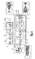
- FIG. 2 illustrates a schematic overview of the functional units of the safety monitoring described here.
- the encoder used is a rotary resolver 50, which is coupled to the shaft of the drive.
- the rotary function detector has transformer-coupled windings, one of which rotates with the shaft, while the two other windings are assigned to the stator and are supplied by a control circuit 40 with two alternating signals.
- the phase position of these alternating signals should correspond to the position or rotational position ⁇ of the drive in the stationary state.
- the tracking control 40 is provided with an integrator as a controller which adjusts a control difference to zero, which state specifies that the phase position of the signal at the output of the tracking control corresponds to the position of the drive.
- the functional units 40, 50 is thus characterized a closed loop.
- the operating signal u 53 of the resolver that is, the signal induced on the rotor winding
- a safety monitor 30 the inner life of which is based on the FIG. 1 will be explained later.
- This safety monitoring outputs an error signal F indicating a condition that should not occur during normal operation of the drive. It can indicate a fault in the mechanics or electrics of the rotary encoder, but it can also register an excessive speed and lead to a shutdown.
- a detuning signal in the sense of a separate, substantially stationary signal ⁇ is supplied to both the control circuit 40 with the tracking control and the safety monitoring 30.
- this signal is once fed into the control loop and the other outside of the control loop in known Height also used.
- This equality of the signals can be used to use the detuning signal ⁇ as a comparison signal (test signal), which is compared in the monitoring circuit 30 with a control signal, which is derived from the useful signal u 53 (as the operating signal of the resolver 50).
- FIG. 1 The more accurate version is the FIG. 1 , Again, the functions described are again, only in a specific implementation.
- the realization can be done in circuit technology either analog or digital.
- the corresponding components can be discrete, or realized by microprocessor technology. It is also possible to use customer-specific components on which analog / digital converters are placed, tables for reading out a sine curve are stored and corresponding control algorithms are executed in sampling control.
- both the control circuit 40, as well as the monitoring circuit 30 is fed by this signal.
- the two stator windings 51 a, 51 b which do not have the same orientation (offset from each other), are fed by an output stage 49, which provides two phase-shifted signals. These are referred to as cosine and sine here when two windings are provided in the resolver 50.
- a tracking controller 42 is provided as a PI controller. He has at least one integral component to provide zero control deviation. This deviation results from the physics of the resolver as a first approximation to the difference of the phase positions ⁇ and ⁇ , more precisely as the sine of this difference. If the control difference can be regulated to zero, the angle ⁇ coincides with the angle ⁇ . This makes it possible to determine the position of the drive. Upstream, in front of an angle integrator 43, a speed is measured, which is denoted by ⁇ (t). The situation results from an integration of the speed with the selected measuring principle.
- two 90 ° out of phase oscillation curves u 51a (t) and u 51b (t) can first be formed digitally and then analogously via tables, which form the control signals for the two stator windings 51 a, 51 b.
- the carrier frequency is a sine wave application, which makes an increased resolution of the position signal possible, up to 21 bits, instead of the usual 16bit, when using a digital carrier frequency signal.
- the modulation ensures a transformational signal transmission even if there is no relative movement of the three indicated windings (two in the stator, one in the rotor).
- Other numbers of windings for example, three windings in the stator as a three-phase system are also usable.
- the low-pass filter 32b filters out the high-frequency components which have been taken out by the demodulation in the input region 41 of the control arrangement 40 or have been inserted by the modulation in the adjustment region 49 of the circuit arrangement 40 for the above-mentioned purposes. Amounting 32 ensures that the drive can be safety-monitored in both directions.
- control signal u 32 This results after filtering a control variable as a control signal u 32 , which is compared with the test signal ⁇ in a comparator circuit 33.
- the comparison can be presented as a summation (with a reversed sign).
- the test signal as a detuning signal and the control signal are "subtractively combined".
- This error signal F can either be compared in amplitude with a span ⁇ u 38 within which it is not generated, for example by the window comparator 38. It can also be linked to a timing circuit, not shown, so that an error signal is not actively output until when the measured error signal u 33 is present for a predetermined (minimum) period of time. This mode of operation can be considered as a "temporary blocking".
- both the window comparator 38 difference signal u 33
- the input of the follower controller 42 should not bear stationary any signal component. This is different for the unwanted operating state to be detected.
- the output of the error signal F occurs in the event of a deviation or leaving the compensation case in the safety monitoring.
- the compensation case is the condition with electrically and mechanically properly connected and operating function resolver 50.
- This compensation case need not be a complete compensation of the signals in the subtraction point 33, but may be a "substantially compensation” as described by the tolerance voltage and time monitoring before a definite output of the error signal F results.
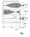
- the two output signals u51a (t) and u51b (t) are signals at a carrier frequency which are modulated by the modulator 44. This carrier frequency is only hinted at in the "sampled” (sampled) signal, while the envelope reflects the rotational frequency of the rotor. These two frequencies are significantly different; the modulation signal used in the tracking control can be in the range of 4 to 6 kHz (see page 4, last paragraph).
- test signal ⁇ which is assumed to be constant in the example, is modulated by the carrier frequency from the modulator 44 as an amplitude-wise small signal ⁇ 'at u53, here in example with a small amplitude below 200 mV.
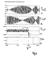
- the modulated test signal ⁇ ' can be seen in both error cases, in two different amplitude representations, cf. in each case the diagram (c) of Figures 3 and 4 ,
- the signal ⁇ 'shown here is the modulated signal ⁇ modulated by the modulator 44.
- the two output signals u51a (t) and u51b (t) are shown as sine-cosine signals modulated by the modulator 44, in the temporal range around the error case, see. in each case the diagrams (a) and (b) of Figures 3 and 4 ,
- the error signal F of the diagrams (f) as output of the window comparator 38 switches to (logical) zero.
- the error signal F becomes a time-dependent signal F (t) when the time is the independent amount.
- the example of the Figures 3 and 4 at the time 120 msec occurring error case is detected at an interruption of the line to the stator winding 51b practically immediately, by a very high signal amplitude of the voltage u53 (t).
- a missing signal ⁇ 'in FIG. 4 , Figure (c) is recognized as an error case with only a small time delay of slightly more than 4 msec due to the delay 32b provided in the circuit 30 and the given very small signal swing of the test signal at the output of the winding 53.
- the low-pass filter 32b as a component of the filter 32 with the magnitude formation 32a filters out high-frequency components which are taken out (in parallel) by the demodulation in the input region 41 of the control arrangement 40.
- This smoothing 32b affects a time delay for a given window comparator 38 and a predetermined threshold, until F (t) responds.
Landscapes
- Physics & Mathematics (AREA)
- General Physics & Mathematics (AREA)
- Engineering & Computer Science (AREA)
- Automation & Control Theory (AREA)
- Transmission And Conversion Of Sensor Element Output (AREA)
- Testing Of Short-Circuits, Discontinuities, Leakage, Or Incorrect Line Connections (AREA)
Claims (29)
- Procédé de détection d'états de fonctionnement non désirés d'un entraînement ou d'un dispositif d'entraînement, dans lequel(a) un capteur de mesure (50) couplé en transformation entre un côté stator et un côté rotor envoie un signal de fonctionnement (u53) à un circuit de commande (40) pour détecter une valeur de position ou une valeur de vitesse de rotation de l'entraînement, le circuit de commande (40) mettant en oeuvre un asservissement de suivi (42,49) en vue de calculer et d'émettre au moins une valeur de vitesse de rotation (ω) ou une valeur de position à partir du signal de fonctionnement (u53) :(b) un signal d'essai (ε) est amené à une surveillance de sécurité (30) destinée à déterminer et émettre un signal d'erreur (F), ledit signal d'essai étant amené également au circuit de commande (40) ;(c) le signal d'erreur (F) est émis lorsqu'il se produit un état de fonctionnement non désiré.
- Procédé selon la revendication 1, dans lequel le même signal de fonctionnement (u53) du capteur de mesure (50) couplé en transformation est amené à la surveillance de sécurité (30) et au circuit de commande (40).
- Procédé selon la revendication 1, dans lequel l'état de fonctionnement non désiré est un court-circuit au niveau du capteur de mesure (50) ou de ses lignes de connexion.
- Procédé selon la revendication 1, dans lequel le signal d'essai (ε) est sensiblement constant.
- Procédé selon la revendication 1 ou 4, dans lequel le signal d'essai est un signal d'angle.
- Procédé selon la revendication 1 ou 5, dans lequel le signal d'essai (ε) intervient à un emplacement du circuit de commande (40), qui se situe en amont d'au moins un intégrateur (42,43).
- Procédé selon la revendication 1, dans lequel l'état de fonctionnement non désiré est l'un au moins des états suivants :(i) la surélévation de la vitesse de rotation ;(ii) le dépassement d'une valeur de rotation limite prédéterminée ;(iii) le défaut électrique dans le capteur de mesure (50) ;(iv) le défaut électrique au niveau des bornes ou du câblage du capteur de mesure (50) ;(v) le défaut mécanique au niveau du capteur de mesure (50).
- Procédé selon la revendication 1, dans lequel le capteur de mesure (50) est un générateur de signal destiné à déterminer ou calculer au moins un signal de fonctionnement de la technique d'entraînement au niveau du dispositif d'entraînement.
- Procédé selon la revendication 8, dans lequel le capteur de mesure est réalisé sous la forme d'un synchro-décomposeur ou résolveur.
- Procédé selon la revendication 2, dans lequel la surveillance de sécurité (30) influe fonctionnellement sur le signal de fonctionnement (u53) du côté entrée ou initialement (31,32), tout comme le circuit de commande (40), mais séparément de celui-ci.
- Procédé selon la revendication 10, dans lequel l'influence séparée est indépendante d'une influence correspondante dans le circuit de commande (40).
- Procédé selon la revendication 10, dans lequel l'influence séparée comprend une conversion analogique-numérique et un lissage (32b) en vue d'une suppression d'une composante à haute fréquence (44) du signal de fonctionnement (u53).
- Procédé selon la revendication 12, dans lequel le signal de fonctionnement influencé et lissé est réuni avec le signal d'essai (ε) en formant une différence (33), afin d'obtenir un signal de différence (u33)·
- Procédé selon la revendication 13, dans lequel une marge de tolérance (Δu38) est comparée au signal de différence (u33) afin d'émettre le signal d'erreur (F ; F(t)), si le signal de différence quitte la marge de tolérance.
- Procédé selon la revendication 1, dans lequel le capteur de mesure (50) est monté sur un arbre de l'entraînement, afin d'émettre le signal de fonctionnement (u53) en fonction de la rotation de l'arbre pour le délivrer à titre de signal de sortie à un enroulement transformateur (53) couplé mécaniquement à l'arbre.
- Procédé selon la revendication 1, pour détecter ou reconnaître des influences perturbatrices sur l'entraînement, qui ne peuvent pas être détectées et compensées par asservissement, au moyen du capteur de mesure (50) dont le signal de sortie (u53) est utilisé comme signal de fonctionnement pour la régulation de l'entraînement par asservissement, dans lequel(i) le signal de fonctionnement (u53) est amené à titre de signal utile et le signal d'essai est amené à titre signal de désaccord aussi bien au circuit de commande (40) disposé en aval du capteur de mesure (50) qu'au circuit de surveillance (30) ;(ii) le signal de désaccord et le signal utile sont combinés par voie soustractive (33) dans le circuit de surveillance ;(iii) lorsqu'une compensation établie par la combinaison dans le circuit de surveillance (30,33) est abandonnée, sensiblement un signal d'erreur (F ; F(t)) est généré (38).
- Procédé selon la revendication 16, dans lequel le signal utile dans le circuit de surveillance (30) est lissé, en particulier également redressé (32a), avant de le combiner par voie soustractive.
- Procédé selon la revendication 16, dans lequel la génération du signal d'erreur (F) est brièvement bloquée (38) par un seuil relatif à l'amplitude ou au temps (Δu38).
- Procédé selon la revendication 16, dans lequel une composante à basse fréquence du signal utile est combinée par voie soustractive avec le signal de désaccord (33).
- Procédé selon la revendication 1 ou 16, dans lequel le signal d'essai à titre de signal de désaccord (ε) est un signal au moins continu, en particulier une valeur constante.
- Procédé selon la revendication 20, dans lequel la valeur est une grandeur d'angle ou une grandeur de position (ε).
- Procédé selon la revendication 21, dans lequel la grandeur de position est compensée à titre de décalage (offset) dans la valeur de position mesurée avant d'être transmise à un asservissement de l'entraînement.
- Capteur de mesure comportant un stator et un rotor, destiné au montage sur un arbre d'entraînement et à la mesure de signaux de rotation d'un entraînement, tels que la vitesse de rotation, l'accélération ou la position (α,ω,ϕ), dans lequel(1) un circuit de commande (40) est pourvu d'un asservissement de suivi (42,49) qui alimente au moins deux enroulements (51a,51b) du capteur de mesure (50) par l'intermédiaire d'un élément actionneur (49), ou qui est conçu pour une alimentation correspondante ;(2) un autre enroulement (53) en rotation par rapport au stator est agencé sur le rotor du capteur de mesure (50) en vue d'émettre un signal de fonctionnement (u53) ;(3) il est prévu un circuit de surveillance (30) séparé, auquel le signal de fonctionnement peut être amené tout comme au circuit de commande (40), afin de déterminer et d'émettre un signal d'erreur (F) lorsqu'un cas de compensation est abandonné.
- Capteur de mesure selon la revendication 23, dans lequel un signal de désaccord (ε) peut être amené au circuit de commande (40), signal qui falsifie durablement le résultat de mesure du capteur de mesure et qui peut être filtré à titre de signal de contrôle (u32,u33) hors du signal de fonctionnement (u53).
- Capteur de mesure selon la revendication 24, dans lequel le signal de désaccord (ε) peut être amené également au circuit de surveillance (30), afin de le comparer au signal de contrôle filtré, en particulier de les combiner par voie soustractive.
- Capteur de mesure selon la revendication 23, dans lequel un générateur de fréquence (44) est prévu dans le circuit de commande (40), afin de procéder, conjointement avec un signal continu, en particulier un signal sinusoïdal, à au moins une modulation des signaux de sortie (u51b,u51a) du circuit de commande (40).
- Capteur de mesure selon la revendication 23, dans lequel le circuit de surveillance (30) est séparé du circuit de commande (40).
- Capteur de mesure selon la revendication 23, dans lequel le circuit de surveillance (30) n'est pas agencé sur le capteur de mesure (50).
- Capteur de mesure selon la revendication 23, dans lequel le circuit de commande comprenant l'asservissement de suivi comprend au moins un régulateur intégral (43) - en particulier sous forme de régulateur proportionnel et intégral - auquel peut être amené un écart de régulation qui est sensiblement zéro pour un état stationnaire.
Applications Claiming Priority (3)
| Application Number | Priority Date | Filing Date | Title |
|---|---|---|---|
| DE10305337 | 2003-02-10 | ||
| DE10305337 | 2003-02-10 | ||
| PCT/DE2004/000240 WO2004070924A2 (fr) | 2003-02-10 | 2004-02-10 | Surveillance de securite sans redondance pour un dispositif d'entrainement electrique (avec capteur de mesure) |
Publications (2)
| Publication Number | Publication Date |
|---|---|
| EP1593006A2 EP1593006A2 (fr) | 2005-11-09 |
| EP1593006B1 true EP1593006B1 (fr) | 2014-11-19 |
Family
ID=32841624
Family Applications (1)
| Application Number | Title | Priority Date | Filing Date |
|---|---|---|---|
| EP04709579.9A Expired - Lifetime EP1593006B1 (fr) | 2003-02-10 | 2004-02-10 | Surveillance de securite sans redondance pour un dispositif d'entrainement electrique (avec capteur de mesure) |
Country Status (5)
| Country | Link |
|---|---|
| US (1) | US7723940B2 (fr) |
| EP (1) | EP1593006B1 (fr) |
| CN (2) | CN101334633A (fr) |
| DE (1) | DE112004000326D2 (fr) |
| WO (1) | WO2004070924A2 (fr) |
Families Citing this family (13)
| Publication number | Priority date | Publication date | Assignee | Title |
|---|---|---|---|---|
| US7558655B2 (en) | 2004-09-10 | 2009-07-07 | Ford Global Technologies, Llc | Prognostic method and system for hybrid and electric vehicle components |
| DE102007034060B4 (de) * | 2007-07-20 | 2012-11-08 | Siemens Ag | Stelleinrichtung für ein Auf/Zu-Ventil |
| DE102008024527A1 (de) | 2008-05-25 | 2009-11-26 | Lenze Automation Gmbh | Verfahren und Vorrichtung zur Überwachung eines Drehwinkelaufnehmers |
| US8198841B2 (en) * | 2009-08-19 | 2012-06-12 | GM Global Technology Operations LLC | Method and circuit for processing a resolver fault |
| DE102009046925A1 (de) | 2009-11-20 | 2011-05-26 | Lenze Automation Gmbh | Verfahren, Vorrichtung und System zum Überwachen des Bestimmens eines Rotorwinkels einer rotierenden Welle mittels eines Resolvers |
| DE102010038638B4 (de) | 2010-07-29 | 2019-02-21 | Lenze Automation Gmbh | Verfahren, Vorrichtung und System zum Überwachen des Bestimmens eines Rotorwinkels einer rotierenden Welle mittels eines Resolvers |
| DE102010047269B4 (de) * | 2010-10-01 | 2014-07-17 | Diehl Aerospace Gmbh | Schaltungsanordnung und Verfahren zur Überwachung eines DSPs im Rahmen einer sicherheitskritischen Anwendung |
| JP6207223B2 (ja) * | 2013-05-01 | 2017-10-04 | キヤノン株式会社 | モータ駆動装置およびその制御方法 |
| DE102014103688A1 (de) * | 2014-03-18 | 2015-09-24 | Khs Gmbh | Vorrichtung sowie Verfahren zur Fehlererkennung in Maschinen |
| KR101619593B1 (ko) | 2014-07-08 | 2016-05-10 | 현대자동차주식회사 | 레졸버 고장판단 방법 |
| US9528857B2 (en) * | 2014-10-17 | 2016-12-27 | Infineon Technologies Ag | Time capture based resolver to digital converter |
| DE102018100878A1 (de) * | 2018-01-16 | 2019-07-18 | Ebm-Papst Landshut Gmbh | Verfahren zum Überprüfen eines zeitdiskreten Signalwerts eines Sensors auf Fehlerfreiheit |
| CN108958019B (zh) * | 2018-08-21 | 2024-03-22 | 深圳市多恩技术有限公司 | 安全适配器、串联型安全控制回路及安全控制方法 |
Family Cites Families (18)
| Publication number | Priority date | Publication date | Assignee | Title |
|---|---|---|---|---|
| CH682351A5 (fr) | 1986-10-16 | 1993-08-31 | Sohard Ag | |
| DE3834384A1 (de) | 1988-10-10 | 1990-04-12 | Lenze Gmbh & Co Kg Aerzen | Verfahren und schaltungsanordnung zur erzeugung von digitalen drehzahl- und drehwinkelinformationen mittels eines funktionsdrehmelders |
| US5635810A (en) * | 1995-09-20 | 1997-06-03 | Analog Devices, Inc. | Control system for a permanent magnet synchronous motor |
| DE59706479D1 (de) * | 1996-07-25 | 2002-04-04 | Lust Antriebstechnik Gmbh | Anordnung und Verfahren zum Betreiben einer magnetgelagerten, elektromotorischen Antriebsvorrichtung bei einer Netzstörung |
| DE19635040C1 (de) | 1996-08-29 | 1998-01-15 | Litton Precision Prod Int | Funktionsdrehmelder zur Erzeugung von Signalen mit reduzierten Oberwellenanteilen |
| US6199422B1 (en) | 1997-07-29 | 2001-03-13 | Skf Condition Monitoring, Inc. | Method and system for fast probe failure determination |
| DE59814122D1 (de) * | 1997-12-06 | 2007-12-20 | Elan Schaltelemente Gmbh & Co | Verfahren zur Überwachung einer technischen Anlage, insbesondere eines Handhabungsgerätes, sowie Überwachungs- und Steuergerät |
| DE19816046A1 (de) * | 1998-04-09 | 1999-10-28 | Bosch Gmbh Robert | Sicherheitsvorrichtung für einen Antrieb |
| JP2000074694A (ja) * | 1998-08-27 | 2000-03-14 | Hitachi Ltd | 回転センサの異常検出装置及び異常検出方法 |
| DE19908230A1 (de) * | 1999-02-25 | 2000-08-31 | Heidelberger Druckmasch Ag | Vorrichtung zur Überwachung von sicherheitsrelevanten Vorgängen an Maschinen |
| EP1121740A1 (fr) * | 1999-08-07 | 2001-08-08 | Robert Bosch Gmbh | Dispositif pour surveiller le systeme de mesure d'une commande electrique |
| DE10011410A1 (de) * | 2000-03-09 | 2001-09-20 | Bosch Gmbh Robert | Vorrichtung zur sicheren Signalerzeugung |
| JP2002310727A (ja) * | 2001-04-13 | 2002-10-23 | Mitsubishi Electric Corp | 位置検出装置の異常検出装置およびその方法 |
| EP1253490B1 (fr) * | 2001-04-25 | 2011-08-17 | Siemens Aktiengesellschaft | Procédé et dispositif de surveillance sécurisée de la vitesse |
| JP3630410B2 (ja) * | 2001-05-22 | 2005-03-16 | 三菱電機株式会社 | 位置検出装置および異常検出装置 |
| JP3758563B2 (ja) * | 2001-12-04 | 2006-03-22 | 豊田工機株式会社 | 位置検出器の補正方法、及び、電気式動力舵取装置 |
| JP3812739B2 (ja) * | 2002-05-28 | 2006-08-23 | 三菱電機株式会社 | モータ異常検出装置及び電動パワーステアリング制御装置 |
| JP2006023164A (ja) * | 2004-07-07 | 2006-01-26 | Mitsubishi Electric Corp | レゾルバ故障診断回路 |
-
2004
- 2004-02-10 EP EP04709579.9A patent/EP1593006B1/fr not_active Expired - Lifetime
- 2004-02-10 WO PCT/DE2004/000240 patent/WO2004070924A2/fr not_active Ceased
- 2004-02-10 CN CNA2008101343643A patent/CN101334633A/zh active Pending
- 2004-02-10 US US10/544,931 patent/US7723940B2/en not_active Expired - Lifetime
- 2004-02-10 CN CNB2004800039256A patent/CN100559308C/zh not_active Expired - Fee Related
- 2004-02-10 DE DE112004000326T patent/DE112004000326D2/de not_active Withdrawn - After Issue
Also Published As
| Publication number | Publication date |
|---|---|
| WO2004070924A3 (fr) | 2004-11-25 |
| US20060186891A1 (en) | 2006-08-24 |
| US7723940B2 (en) | 2010-05-25 |
| CN1748186A (zh) | 2006-03-15 |
| CN101334633A (zh) | 2008-12-31 |
| CN100559308C (zh) | 2009-11-11 |
| EP1593006A2 (fr) | 2005-11-09 |
| WO2004070924A2 (fr) | 2004-08-19 |
| DE112004000326D2 (de) | 2005-11-24 |
Similar Documents
| Publication | Publication Date | Title |
|---|---|---|
| EP1593006B1 (fr) | Surveillance de securite sans redondance pour un dispositif d'entrainement electrique (avec capteur de mesure) | |
| DE2926378C2 (de) | Schaltungsanordnung zum Wiederanfahren eines verzögerten Induktionsmotors | |
| EP2309641B1 (fr) | Procédé et dispositif de surveillance sécurisé contre les erreurs d'un entraînement à moteur électrique | |
| DE69805641T2 (de) | Gerät und verfahren zur steuerung eines synchronmotors mit permanentmagnet | |
| EP2460056B1 (fr) | Procédé et dispositif de surveillance de l'absence d'erreur d'une grandeur de déplacement sur un mécanisme d'entraînement électrique | |
| DE4330823C2 (de) | Antriebsvorrichtung mit einer Sicherheitseinrichtung für den Sonderbetrieb | |
| EP2132440B1 (fr) | Dispositif d'entraînement pour entraîner plusieurs essieux | |
| DE112020000915T5 (de) | Motorsteuervorrichtung und Elektrobremsvorrichtung die sie verwendet, und Motorsteuerverfahren und Elektrobremssteuerverfahren, das es verwendet | |
| DE102015226382A1 (de) | Verfahren und Anordnung zur Überwachung einer PSM-Maschine | |
| DE102018132413A1 (de) | Verfahren zum Erfassen unterschiedlicher Schwingungen einer Windenergieanlage | |
| EP1253490B1 (fr) | Procédé et dispositif de surveillance sécurisée de la vitesse | |
| DE102016100680A1 (de) | Windkraftanlage | |
| DE102010051873B4 (de) | Integrierte Schaltungsanordnung und Verfahren zur Signalüberwachung | |
| EP2746732B2 (fr) | Dispositif de transducteur et procédé destinés à la détermination d'une position | |
| WO2004005939A1 (fr) | Dispositif permettant de determiner la vitesse de rotation d'une partie de machine en rotation | |
| DE3424247C2 (fr) | ||
| EP1589653A2 (fr) | Dispositif pour entraíner un moteur synchrone | |
| DE102013204600A1 (de) | Windkraftanlage mit Frequenzmessung | |
| DE102015003499B4 (de) | Multiturn-Drehgeber mit erhöhten Sicherheitsanforderungen | |
| DE2744941A1 (de) | Verfahren und einrichtung zur ueberwachung eines stellungsreglers auf stoerungen | |
| DE3926705A1 (de) | Anordnung und vorrichtung zum regeln eines gasturbinentriebwerks | |
| EP3895303A1 (fr) | Procédé de surveillance d'un système d'entraînement et système d'entraînement | |
| DE102016121488B4 (de) | Verfahren zur detektion eines rotorlagewinkels in einer elektrischen maschine und steuerung dafür sowie damit ausgestattetes antriebssystem | |
| DE102021105352A1 (de) | Sensor, insbesondere Drehmoment- oder Drehwinkelsensor | |
| EP3296184B1 (fr) | Dispositif et procede destine a surveiller l'arret de vehicules, en particulier des vehicules sur rails |
Legal Events
| Date | Code | Title | Description |
|---|---|---|---|
| PUAI | Public reference made under article 153(3) epc to a published international application that has entered the european phase |
Free format text: ORIGINAL CODE: 0009012 |
|
| 17P | Request for examination filed |
Effective date: 20050715 |
|
| AK | Designated contracting states |
Kind code of ref document: A2 Designated state(s): AT BE BG CH CY CZ DE DK EE ES FI FR GB GR HU IE IT LI LU MC NL PT RO SE SI SK TR |
|
| AX | Request for extension of the european patent |
Extension state: AL LT LV MK |
|
| DAX | Request for extension of the european patent (deleted) | ||
| RAP1 | Party data changed (applicant data changed or rights of an application transferred) |
Owner name: LENZE AUTOMATION GMBH |
|
| 17Q | First examination report despatched |
Effective date: 20100113 |
|
| GRAP | Despatch of communication of intention to grant a patent |
Free format text: ORIGINAL CODE: EPIDOSNIGR1 |
|
| INTG | Intention to grant announced |
Effective date: 20140717 |
|
| GRAS | Grant fee paid |
Free format text: ORIGINAL CODE: EPIDOSNIGR3 |
|
| GRAA | (expected) grant |
Free format text: ORIGINAL CODE: 0009210 |
|
| RAP1 | Party data changed (applicant data changed or rights of an application transferred) |
Owner name: LENZE AUTOMATION GMBH |
|
| AK | Designated contracting states |
Kind code of ref document: B1 Designated state(s): AT BE BG CH CY CZ DE DK EE ES FI FR GB GR HU IE IT LI LU MC NL PT RO SE SI SK TR |
|
| REG | Reference to a national code |
Ref country code: GB Ref legal event code: FG4D Free format text: NOT ENGLISH |
|
| REG | Reference to a national code |
Ref country code: CH Ref legal event code: EP |
|
| REG | Reference to a national code |
Ref country code: AT Ref legal event code: REF Ref document number: 697359 Country of ref document: AT Kind code of ref document: T Effective date: 20141215 |
|
| REG | Reference to a national code |
Ref country code: IE Ref legal event code: FG4D Free format text: LANGUAGE OF EP DOCUMENT: GERMAN |
|
| REG | Reference to a national code |
Ref country code: DE Ref legal event code: R096 Ref document number: 502004014767 Country of ref document: DE Effective date: 20141231 |
|
| REG | Reference to a national code |
Ref country code: NL Ref legal event code: VDEP Effective date: 20141119 |
|
| PG25 | Lapsed in a contracting state [announced via postgrant information from national office to epo] |
Ref country code: ES Free format text: LAPSE BECAUSE OF FAILURE TO SUBMIT A TRANSLATION OF THE DESCRIPTION OR TO PAY THE FEE WITHIN THE PRESCRIBED TIME-LIMIT Effective date: 20141119 Ref country code: FI Free format text: LAPSE BECAUSE OF FAILURE TO SUBMIT A TRANSLATION OF THE DESCRIPTION OR TO PAY THE FEE WITHIN THE PRESCRIBED TIME-LIMIT Effective date: 20141119 Ref country code: NL Free format text: LAPSE BECAUSE OF FAILURE TO SUBMIT A TRANSLATION OF THE DESCRIPTION OR TO PAY THE FEE WITHIN THE PRESCRIBED TIME-LIMIT Effective date: 20141119 Ref country code: PT Free format text: LAPSE BECAUSE OF FAILURE TO SUBMIT A TRANSLATION OF THE DESCRIPTION OR TO PAY THE FEE WITHIN THE PRESCRIBED TIME-LIMIT Effective date: 20150319 |
|
| PG25 | Lapsed in a contracting state [announced via postgrant information from national office to epo] |
Ref country code: SE Free format text: LAPSE BECAUSE OF FAILURE TO SUBMIT A TRANSLATION OF THE DESCRIPTION OR TO PAY THE FEE WITHIN THE PRESCRIBED TIME-LIMIT Effective date: 20141119 Ref country code: GR Free format text: LAPSE BECAUSE OF FAILURE TO SUBMIT A TRANSLATION OF THE DESCRIPTION OR TO PAY THE FEE WITHIN THE PRESCRIBED TIME-LIMIT Effective date: 20150220 Ref country code: CY Free format text: LAPSE BECAUSE OF FAILURE TO SUBMIT A TRANSLATION OF THE DESCRIPTION OR TO PAY THE FEE WITHIN THE PRESCRIBED TIME-LIMIT Effective date: 20141119 |
|
| PG25 | Lapsed in a contracting state [announced via postgrant information from national office to epo] |
Ref country code: SK Free format text: LAPSE BECAUSE OF FAILURE TO SUBMIT A TRANSLATION OF THE DESCRIPTION OR TO PAY THE FEE WITHIN THE PRESCRIBED TIME-LIMIT Effective date: 20141119 Ref country code: CZ Free format text: LAPSE BECAUSE OF FAILURE TO SUBMIT A TRANSLATION OF THE DESCRIPTION OR TO PAY THE FEE WITHIN THE PRESCRIBED TIME-LIMIT Effective date: 20141119 Ref country code: EE Free format text: LAPSE BECAUSE OF FAILURE TO SUBMIT A TRANSLATION OF THE DESCRIPTION OR TO PAY THE FEE WITHIN THE PRESCRIBED TIME-LIMIT Effective date: 20141119 Ref country code: RO Free format text: LAPSE BECAUSE OF FAILURE TO SUBMIT A TRANSLATION OF THE DESCRIPTION OR TO PAY THE FEE WITHIN THE PRESCRIBED TIME-LIMIT Effective date: 20141119 Ref country code: DK Free format text: LAPSE BECAUSE OF FAILURE TO SUBMIT A TRANSLATION OF THE DESCRIPTION OR TO PAY THE FEE WITHIN THE PRESCRIBED TIME-LIMIT Effective date: 20141119 |
|
| REG | Reference to a national code |
Ref country code: DE Ref legal event code: R097 Ref document number: 502004014767 Country of ref document: DE |
|
| PLBE | No opposition filed within time limit |
Free format text: ORIGINAL CODE: 0009261 |
|
| STAA | Information on the status of an ep patent application or granted ep patent |
Free format text: STATUS: NO OPPOSITION FILED WITHIN TIME LIMIT |
|
| PG25 | Lapsed in a contracting state [announced via postgrant information from national office to epo] |
Ref country code: LU Free format text: LAPSE BECAUSE OF FAILURE TO SUBMIT A TRANSLATION OF THE DESCRIPTION OR TO PAY THE FEE WITHIN THE PRESCRIBED TIME-LIMIT Effective date: 20150210 |
|
| REG | Reference to a national code |
Ref country code: CH Ref legal event code: PL |
|
| 26N | No opposition filed |
Effective date: 20150820 |
|
| GBPC | Gb: european patent ceased through non-payment of renewal fee |
Effective date: 20150219 |
|
| PG25 | Lapsed in a contracting state [announced via postgrant information from national office to epo] |
Ref country code: MC Free format text: LAPSE BECAUSE OF FAILURE TO SUBMIT A TRANSLATION OF THE DESCRIPTION OR TO PAY THE FEE WITHIN THE PRESCRIBED TIME-LIMIT Effective date: 20141119 Ref country code: LI Free format text: LAPSE BECAUSE OF NON-PAYMENT OF DUE FEES Effective date: 20150228 Ref country code: CH Free format text: LAPSE BECAUSE OF NON-PAYMENT OF DUE FEES Effective date: 20150228 |
|
| REG | Reference to a national code |
Ref country code: IE Ref legal event code: MM4A |
|
| REG | Reference to a national code |
Ref country code: FR Ref legal event code: ST Effective date: 20151030 |
|
| PG25 | Lapsed in a contracting state [announced via postgrant information from national office to epo] |
Ref country code: IT Free format text: LAPSE BECAUSE OF FAILURE TO SUBMIT A TRANSLATION OF THE DESCRIPTION OR TO PAY THE FEE WITHIN THE PRESCRIBED TIME-LIMIT Effective date: 20141119 |
|
| PG25 | Lapsed in a contracting state [announced via postgrant information from national office to epo] |
Ref country code: GB Free format text: LAPSE BECAUSE OF NON-PAYMENT OF DUE FEES Effective date: 20150219 Ref country code: IE Free format text: LAPSE BECAUSE OF NON-PAYMENT OF DUE FEES Effective date: 20150210 |
|
| PG25 | Lapsed in a contracting state [announced via postgrant information from national office to epo] |
Ref country code: FR Free format text: LAPSE BECAUSE OF NON-PAYMENT OF DUE FEES Effective date: 20150302 Ref country code: SI Free format text: LAPSE BECAUSE OF FAILURE TO SUBMIT A TRANSLATION OF THE DESCRIPTION OR TO PAY THE FEE WITHIN THE PRESCRIBED TIME-LIMIT Effective date: 20141119 |
|
| REG | Reference to a national code |
Ref country code: AT Ref legal event code: MM01 Ref document number: 697359 Country of ref document: AT Kind code of ref document: T Effective date: 20150210 |
|
| PG25 | Lapsed in a contracting state [announced via postgrant information from national office to epo] |
Ref country code: AT Free format text: LAPSE BECAUSE OF NON-PAYMENT OF DUE FEES Effective date: 20150210 |
|
| PG25 | Lapsed in a contracting state [announced via postgrant information from national office to epo] |
Ref country code: BG Free format text: LAPSE BECAUSE OF FAILURE TO SUBMIT A TRANSLATION OF THE DESCRIPTION OR TO PAY THE FEE WITHIN THE PRESCRIBED TIME-LIMIT Effective date: 20141119 Ref country code: HU Free format text: LAPSE BECAUSE OF FAILURE TO SUBMIT A TRANSLATION OF THE DESCRIPTION OR TO PAY THE FEE WITHIN THE PRESCRIBED TIME-LIMIT; INVALID AB INITIO Effective date: 20040210 |
|
| PG25 | Lapsed in a contracting state [announced via postgrant information from national office to epo] |
Ref country code: BE Free format text: LAPSE BECAUSE OF NON-PAYMENT OF DUE FEES Effective date: 20150228 |
|
| PG25 | Lapsed in a contracting state [announced via postgrant information from national office to epo] |
Ref country code: TR Free format text: LAPSE BECAUSE OF FAILURE TO SUBMIT A TRANSLATION OF THE DESCRIPTION OR TO PAY THE FEE WITHIN THE PRESCRIBED TIME-LIMIT Effective date: 20141119 |
|
| PGFP | Annual fee paid to national office [announced via postgrant information from national office to epo] |
Ref country code: DE Payment date: 20190429 Year of fee payment: 16 |
|
| REG | Reference to a national code |
Ref country code: DE Ref legal event code: R119 Ref document number: 502004014767 Country of ref document: DE |
|
| PG25 | Lapsed in a contracting state [announced via postgrant information from national office to epo] |
Ref country code: DE Free format text: LAPSE BECAUSE OF NON-PAYMENT OF DUE FEES Effective date: 20200901 |