EP1593006B1 - Non-redundant safety monitoring for an electric drive mechanism (with a sensor) - Google Patents
Non-redundant safety monitoring for an electric drive mechanism (with a sensor) Download PDFInfo
- Publication number
- EP1593006B1 EP1593006B1 EP04709579.9A EP04709579A EP1593006B1 EP 1593006 B1 EP1593006 B1 EP 1593006B1 EP 04709579 A EP04709579 A EP 04709579A EP 1593006 B1 EP1593006 B1 EP 1593006B1
- Authority
- EP
- European Patent Office
- Prior art keywords
- signal
- sensor
- control
- control circuit
- operating
- Prior art date
- Legal status (The legal status is an assumption and is not a legal conclusion. Google has not performed a legal analysis and makes no representation as to the accuracy of the status listed.)
- Expired - Lifetime
Links
- 238000012544 monitoring process Methods 0.000 title claims description 44
- 238000012360 testing method Methods 0.000 claims description 35
- 238000000034 method Methods 0.000 claims description 29
- 238000004804 winding Methods 0.000 claims description 20
- 238000005516 engineering process Methods 0.000 claims description 11
- 230000001133 acceleration Effects 0.000 claims description 3
- 238000006243 chemical reaction Methods 0.000 claims description 2
- 238000009499 grossing Methods 0.000 claims description 2
- 238000012806 monitoring device Methods 0.000 claims 3
- 238000010586 diagram Methods 0.000 description 7
- 238000005259 measurement Methods 0.000 description 5
- 230000015572 biosynthetic process Effects 0.000 description 2
- 230000008859 change Effects 0.000 description 2
- 230000007774 longterm Effects 0.000 description 2
- 230000007257 malfunction Effects 0.000 description 2
- 230000001105 regulatory effect Effects 0.000 description 2
- 238000005070 sampling Methods 0.000 description 2
- 208000010201 Exanthema Diseases 0.000 description 1
- 230000008901 benefit Effects 0.000 description 1
- 230000000903 blocking effect Effects 0.000 description 1
- 230000000052 comparative effect Effects 0.000 description 1
- 230000008878 coupling Effects 0.000 description 1
- 238000010168 coupling process Methods 0.000 description 1
- 238000005859 coupling reaction Methods 0.000 description 1
- 230000002950 deficient Effects 0.000 description 1
- 238000001514 detection method Methods 0.000 description 1
- 238000011156 evaluation Methods 0.000 description 1
- 201000005884 exanthem Diseases 0.000 description 1
- 230000005284 excitation Effects 0.000 description 1
- 238000001914 filtration Methods 0.000 description 1
- 238000003780 insertion Methods 0.000 description 1
- 230000037431 insertion Effects 0.000 description 1
- 230000010354 integration Effects 0.000 description 1
- 230000010355 oscillation Effects 0.000 description 1
- 206010037844 rash Diseases 0.000 description 1
- 230000004044 response Effects 0.000 description 1
- 230000008054 signal transmission Effects 0.000 description 1
- 239000013589 supplement Substances 0.000 description 1
- 230000002123 temporal effect Effects 0.000 description 1
- 230000036962 time dependent Effects 0.000 description 1
- 238000011144 upstream manufacturing Methods 0.000 description 1
Images

Classifications
-
- G—PHYSICS
- G05—CONTROLLING; REGULATING
- G05B—CONTROL OR REGULATING SYSTEMS IN GENERAL; FUNCTIONAL ELEMENTS OF SUCH SYSTEMS; MONITORING OR TESTING ARRANGEMENTS FOR SUCH SYSTEMS OR ELEMENTS
- G05B23/00—Testing or monitoring of control systems or parts thereof
- G05B23/02—Electric testing or monitoring
- G05B23/0205—Electric testing or monitoring by means of a monitoring system capable of detecting and responding to faults
- G05B23/0218—Electric testing or monitoring by means of a monitoring system capable of detecting and responding to faults characterised by the fault detection method dealing with either existing or incipient faults
- G05B23/0256—Electric testing or monitoring by means of a monitoring system capable of detecting and responding to faults characterised by the fault detection method dealing with either existing or incipient faults injecting test signals and analyzing monitored process response, e.g. injecting the test signal while interrupting the normal operation of the monitored system; superimposing the test signal onto a control signal during normal operation of the monitored system
-
- G—PHYSICS
- G05—CONTROLLING; REGULATING
- G05B—CONTROL OR REGULATING SYSTEMS IN GENERAL; FUNCTIONAL ELEMENTS OF SUCH SYSTEMS; MONITORING OR TESTING ARRANGEMENTS FOR SUCH SYSTEMS OR ELEMENTS
- G05B9/00—Safety arrangements
- G05B9/02—Safety arrangements electric
Definitions
- the invention relates to a method for monitoring a particular electrically driven drive, which usually consists of a drive motor, a shaft and coupled to the shaft drive object (output).
- a particular electrically driven drive which usually consists of a drive motor, a shaft and coupled to the shaft drive object (output).
- at least one measurement signal is required, usually also several measurement signals, which are usually called in the drive technology speed, acceleration and position (or rotation angle).
- the invention relates both to a method for detecting an undesired operating state, as well as to a sensor, which is secured against failure.
- This encoder is preferably a "rotary", which is commonly referred to in the drive technology as a resolver.
- a resolver is a transformer-coupled measuring transmitter which emits a useful signal, from which at least one system signal relevant for the drive technology can be determined.
- the rotary function detector is a rotating transformer whose output voltage has a clear relationship to the position of its shaft.
- Function rotary encoders are therefore suitable as absolute angle encoders with a rotation range of more than 360 °, cf. for example, the DE-C 196 35 040 (Litton ), there column 1, lines 15 to 20 and column 2, lines 9 to 13. While refers in the related font of the rotary resolver to the purely mechanical structure, cf. the local FIG. 2 , the determination of the desired system sizes is also with the DE-C 38 34 384 (Lenze ) possible. In the latter document, a method and a circuit arrangement for generating digital rotational speeds and rotational angle information by means of a functional rotary encoder is described.
- FIG. 1 shows a control circuit as a tracking controller, with the circuit arrangement is fed from an operating signal of the rotor winding of the resolver, which controls a control difference with a controller to zero.
- the output of the controller then the speed and its integral of the position (there called “angle output").
- the reliable in safety encoder according to claim 23 allows the generation of an error signal via a monitoring circuit, wherein a non-permissible operating state detected and the error signal is generated accordingly.
- a detuning signal is used, which is fed into the closed control loop of the encoder.
- This permanent feed of the detuning signal can be detected outside the measuring loop in a separate monitoring circuit, where its presence is monitored and in the absence of this - in the monitoring circuit "control signal" - detuned signal, the error signal is emitted accordingly.
- the monitoring circuit is also supplied with the output signal of the encoder (claim 16), which in the same way the closed Control circuit is supplied, but this operating signal is part of the closed loop control. Only the monitoring circuit is outside the closed control loop and is not included with its output signal in the determination of the control signal.
- the monitoring circuit takes over the detection of the error, wherein in the case of the use of a transformer-coupled encoder in the sense of "Softstapmelders" a test signal is fed near the tracking circuit of the circuit arrangement of the operating rotary field. Especially at the point of the control deviation, ie before the controller having at least one integral component of the tracking circuit, the insertion of the test signal can take place.
- This test signal thus influences the entire control loop and represents figuratively a detuning, if it is assumed that at the input of the controller of the circuit arrangement in the stationary case, there is a control deviation of zero. This steady-state deviation is still present, only it is influenced by the feed of the test signal, which in turn is supplied to the monitoring circuit in the same way (in the same amplitude).
- the safety monitor may detect that a control signal does not equal zero when the detuning signal is subtracted. This leads to the conclusion that there is some electrical or mechanical fault on the encoder, which leads to a safety shutdown, which is initiated at a low voltage level.
- the presence of the test signal (claim 4, 5 or 6) is constantly monitored in the safety monitoring. In this case, the test signal can be substantially constant. It can be fed in as an angle signal, specifically at the previously described position of the control deviation of the integral controller of the tracking control.
- Both the security monitoring, as well as the tracking control is preferably not only the test signal, but also the output signal (operating signal) of the resolver fed (claim 2, 16).
- the determination of the speed value or the position value takes place in the follow-up control.
- test signal in the safety monitoring is first filtered out of the modulated operating signal of the rotary function, and this no specific demodulation must be made in the safety monitoring, as it is done in the tracking control by a carrier frequency, can be filtered with a simple circuit technology, the high frequency component of the operating signal (Claim 10, 11 and 12 and 17). It should be noted that the functionality should be comparable, which is used in the initial section of the tracking control and safety monitoring.
- the control signal obtained by the functionally identical influencing of the signal should substantially correspond in magnitude to the test signal, so that a subtractive combination (in the sense of a comparison of the magnitude variables) leads to a zero result (claim 13).
- a tolerance range may be provided, for example by a window comparator, there may also be a time lock before the error signal is activated (claim 18, 14).
- error signals to be detected are not those which can be “detected and regulated by control technology”. Such detectable disturbing influences should be detected by the regular control or control, while the "disturbance variables” that can not be influenced by this control are separately recorded by the security monitoring in the sense of safety-relevant errors (claim 16).
- this signal should be at least continuous, especially as a constant value (claims 20, 21 and 22). Although it is fed into the control loop, but can be taken into account in its actual size in the actual regulation (claim 22). Because it is deterministic and known in amplitude, it can also be subtractively combined in security surveillance, which Safety monitoring of this test signal determined as detuning the control deviation of the follower in the sense of a control signal separately.
- the modulation signal used in the tracking control can be in the range of 4 to 6 kHz, in particular as a sinusoidal signal, in order to obtain a higher resolution by sampling the course of this signal or the waveform. For example, 8 times is sampled within a sine wave, which is particularly advantageous at slow speeds.
- the detuning signal also: test signal
- the detuning signal also: test signal
- the detuning signal also: test signal
- causes of faults are defective cables and connections that can be detected with the invention regardless of the type of fault in the area of the encoder.
- the safety monitoring initially extends to the encoder itself (claim 20), with this monitoring of the encoder but also the drive as a whole and the object driven by the drive is also monitored in safety.
- the monitoring takes place at a potentially low level, ie close to the control voltage, not on the power side.
- FIG. 2 illustrates a schematic overview of the functional units of the safety monitoring described here.
- the encoder used is a rotary resolver 50, which is coupled to the shaft of the drive.
- the rotary function detector has transformer-coupled windings, one of which rotates with the shaft, while the two other windings are assigned to the stator and are supplied by a control circuit 40 with two alternating signals.
- the phase position of these alternating signals should correspond to the position or rotational position ⁇ of the drive in the stationary state.
- the tracking control 40 is provided with an integrator as a controller which adjusts a control difference to zero, which state specifies that the phase position of the signal at the output of the tracking control corresponds to the position of the drive.
- the functional units 40, 50 is thus characterized a closed loop.
- the operating signal u 53 of the resolver that is, the signal induced on the rotor winding
- a safety monitor 30 the inner life of which is based on the FIG. 1 will be explained later.
- This safety monitoring outputs an error signal F indicating a condition that should not occur during normal operation of the drive. It can indicate a fault in the mechanics or electrics of the rotary encoder, but it can also register an excessive speed and lead to a shutdown.
- a detuning signal in the sense of a separate, substantially stationary signal ⁇ is supplied to both the control circuit 40 with the tracking control and the safety monitoring 30.
- this signal is once fed into the control loop and the other outside of the control loop in known Height also used.
- This equality of the signals can be used to use the detuning signal ⁇ as a comparison signal (test signal), which is compared in the monitoring circuit 30 with a control signal, which is derived from the useful signal u 53 (as the operating signal of the resolver 50).
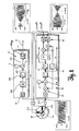
- FIG. 1 The more accurate version is the FIG. 1 , Again, the functions described are again, only in a specific implementation.
- the realization can be done in circuit technology either analog or digital.
- the corresponding components can be discrete, or realized by microprocessor technology. It is also possible to use customer-specific components on which analog / digital converters are placed, tables for reading out a sine curve are stored and corresponding control algorithms are executed in sampling control.
- both the control circuit 40, as well as the monitoring circuit 30 is fed by this signal.
- the two stator windings 51 a, 51 b which do not have the same orientation (offset from each other), are fed by an output stage 49, which provides two phase-shifted signals. These are referred to as cosine and sine here when two windings are provided in the resolver 50.
- a tracking controller 42 is provided as a PI controller. He has at least one integral component to provide zero control deviation. This deviation results from the physics of the resolver as a first approximation to the difference of the phase positions ⁇ and ⁇ , more precisely as the sine of this difference. If the control difference can be regulated to zero, the angle ⁇ coincides with the angle ⁇ . This makes it possible to determine the position of the drive. Upstream, in front of an angle integrator 43, a speed is measured, which is denoted by ⁇ (t). The situation results from an integration of the speed with the selected measuring principle.
- two 90 ° out of phase oscillation curves u 51a (t) and u 51b (t) can first be formed digitally and then analogously via tables, which form the control signals for the two stator windings 51 a, 51 b.
- the carrier frequency is a sine wave application, which makes an increased resolution of the position signal possible, up to 21 bits, instead of the usual 16bit, when using a digital carrier frequency signal.
- the modulation ensures a transformational signal transmission even if there is no relative movement of the three indicated windings (two in the stator, one in the rotor).
- Other numbers of windings for example, three windings in the stator as a three-phase system are also usable.
- the low-pass filter 32b filters out the high-frequency components which have been taken out by the demodulation in the input region 41 of the control arrangement 40 or have been inserted by the modulation in the adjustment region 49 of the circuit arrangement 40 for the above-mentioned purposes. Amounting 32 ensures that the drive can be safety-monitored in both directions.
- control signal u 32 This results after filtering a control variable as a control signal u 32 , which is compared with the test signal ⁇ in a comparator circuit 33.
- the comparison can be presented as a summation (with a reversed sign).
- the test signal as a detuning signal and the control signal are "subtractively combined".
- This error signal F can either be compared in amplitude with a span ⁇ u 38 within which it is not generated, for example by the window comparator 38. It can also be linked to a timing circuit, not shown, so that an error signal is not actively output until when the measured error signal u 33 is present for a predetermined (minimum) period of time. This mode of operation can be considered as a "temporary blocking".
- both the window comparator 38 difference signal u 33
- the input of the follower controller 42 should not bear stationary any signal component. This is different for the unwanted operating state to be detected.
- the output of the error signal F occurs in the event of a deviation or leaving the compensation case in the safety monitoring.
- the compensation case is the condition with electrically and mechanically properly connected and operating function resolver 50.
- This compensation case need not be a complete compensation of the signals in the subtraction point 33, but may be a "substantially compensation” as described by the tolerance voltage and time monitoring before a definite output of the error signal F results.
- the two output signals u51a (t) and u51b (t) are signals at a carrier frequency which are modulated by the modulator 44. This carrier frequency is only hinted at in the "sampled” (sampled) signal, while the envelope reflects the rotational frequency of the rotor. These two frequencies are significantly different; the modulation signal used in the tracking control can be in the range of 4 to 6 kHz (see page 4, last paragraph).
- test signal ⁇ which is assumed to be constant in the example, is modulated by the carrier frequency from the modulator 44 as an amplitude-wise small signal ⁇ 'at u53, here in example with a small amplitude below 200 mV.
- the modulated test signal ⁇ ' can be seen in both error cases, in two different amplitude representations, cf. in each case the diagram (c) of Figures 3 and 4 ,
- the signal ⁇ 'shown here is the modulated signal ⁇ modulated by the modulator 44.
- the two output signals u51a (t) and u51b (t) are shown as sine-cosine signals modulated by the modulator 44, in the temporal range around the error case, see. in each case the diagrams (a) and (b) of Figures 3 and 4 ,
- the error signal F of the diagrams (f) as output of the window comparator 38 switches to (logical) zero.
- the error signal F becomes a time-dependent signal F (t) when the time is the independent amount.
- the example of the Figures 3 and 4 at the time 120 msec occurring error case is detected at an interruption of the line to the stator winding 51b practically immediately, by a very high signal amplitude of the voltage u53 (t).
- a missing signal ⁇ 'in FIG. 4 , Figure (c) is recognized as an error case with only a small time delay of slightly more than 4 msec due to the delay 32b provided in the circuit 30 and the given very small signal swing of the test signal at the output of the winding 53.
- the low-pass filter 32b as a component of the filter 32 with the magnitude formation 32a filters out high-frequency components which are taken out (in parallel) by the demodulation in the input region 41 of the control arrangement 40.
- This smoothing 32b affects a time delay for a given window comparator 38 and a predetermined threshold, until F (t) responds.
Landscapes
- Physics & Mathematics (AREA)
- General Physics & Mathematics (AREA)
- Engineering & Computer Science (AREA)
- Automation & Control Theory (AREA)
- Transmission And Conversion Of Sensor Element Output (AREA)
- Testing Of Short-Circuits, Discontinuities, Leakage, Or Incorrect Line Connections (AREA)
Description
Die Erfindung befasst sich mit einem Verfahren zum Überwachen eines insbesondere elektrisch angetriebenen Antriebs, der üblicherweise aus einem Antriebsmotor, einer Welle und einem mit der Welle gekoppelten Antriebsobjekt (Abtrieb) besteht. Bei solchen Antrieben wird zumindest ein Messsignal benötigt, meist auch mehrere Mess-Signale, die in der Antriebstechnik üblicherweise Drehzahl, Beschleunigung und Lage (oder Drehwinkel) genannt werden.The invention relates to a method for monitoring a particular electrically driven drive, which usually consists of a drive motor, a shaft and coupled to the shaft drive object (output). In such drives, at least one measurement signal is required, usually also several measurement signals, which are usually called in the drive technology speed, acceleration and position (or rotation angle).
Die Erfindung bezieht sich dabei sowohl auf ein Verfahren zur Erfassung eines unerwünschten Betriebszustandes, wie auch auf einen Messgeber, der gegen Ausfall gesichert ist. Dieser Messgeber ist bevorzugt ein "Funktionsdrehmelder", der in der Antriebstechnik üblicherweise als Resolver bezeichnet wird. Inhaltlich ist ein Resolver ein transformatorisch gekoppelter Messgeber, der ein Nutzsignal abgibt, aus dem zumindest ein für die Antriebstechnik relevantes Systemsignal bestimmt werden kann.The invention relates both to a method for detecting an undesired operating state, as well as to a sensor, which is secured against failure. This encoder is preferably a "rotary", which is commonly referred to in the drive technology as a resolver. In terms of content, a resolver is a transformer-coupled measuring transmitter which emits a useful signal, from which at least one system signal relevant for the drive technology can be determined.
Vom technischen Funktionsprinzip her ist der Funktionsdrehmelder ein rotierender Transformator, dessen Ausgangsspannung eine eindeutige Beziehung zur Position seiner Welle hat. Funktionsdrehmelder eignen sich deshalb als absolute Winkelgeber mit einem Drehbereich von grösser 360°, vgl. dazu beispielsweise die
Besonders in einer rauen Umgebung, aber auch bei langfristigem Gebrauch muss sichergestellt werden, dass Antriebe keine unzulässige Betriebszustände einnehmen, also keine zu hohen Drehzahlen erfahren, wenn beispielsweise das Messglied für die Drehzahlmessung ausfällt, wie durch einen elektrischen oder mechanischen Fehler im Drehgeber. Solche Probleme werden im Stand der Technik meist durch Redundanz gelöst, namentlich durch Einsatz von mehreren Drehgebern, die dann im Rahmen einer Vergleichsmessung oder einer Mehrheitsentscheidung (bei zumindest drei Messgebern) eine Sicherheitsüberwachung erlauben.Especially in a harsh environment, but also for long-term use, it must be ensured that drives do not assume any impermissible operating states, ie do not experience too high speeds, for example, if the measuring element for the speed measurement fails, as by an electrical or mechanical error in the encoder. Such problems usually become redundant in the prior art solved, in particular by using multiple encoders, which then allow a safety monitoring in the context of a comparison measurement or a majority decision (with at least three encoders).
Wie aus
Es ist eine technische Problemstellung der Erfindung, Sicherheit ohne Redundanz zu ermöglichen, und diese Sicherheit für Betriebssignale in der Antriebstechnik zur Verfügung zu stellen. Es sollen dabei keine zusätzlichen Geber für die genannten Betriebssignale erforderlich sein und dennoch soll eine sicherheitsgerichtete Drehzahlbegrenzung eines Antriebs zur Erzielung hoher Schutzlevel möglich werden.It is a technical problem of the invention to allow security without redundancy, and to provide this security for operating signals in the drive technology. There are no additional encoders for the said operating signals are required and yet a safety-oriented speed limitation of a drive to achieve high levels of protection are possible.
Erreicht wird das gemäß der Erfindung mit einem Verfahren nach Anspruch 1. Der in der Sicherheit zuverlässige Messgeber nach Anspruch 23 ermöglicht die Generierung eines Fehlersignals über eine Überwachungsschaltung, wobei ein nicht zulässiger Betriebszustand erfasst und das Fehlersignal entsprechend erzeugt wird.This is achieved according to the invention with a method according to
Im generellen Bereich der Antriebstechnik wird ein Verstimmungssignal eingesetzt, das in die geschlossene Regelschleife des Messgebers eingespeist wird. Diese dauerhafte Einspeisung des Verstimmungssignals kann außerhalb der Messschleife in einer gesonderten Überwachungsschaltung detektiert werden, wo seine Anwesenheit überwacht wird und bei Ausbleiben dieses - in der Überwachungsschaltung "Kontrollsignal" genannten - Verstimmungssignals wird das Fehlersignal entsprechend abgegeben. Der Überwachungsschaltung wird auch das Ausgangssignal des Messgebers zugeführt (Anspruch 16), welches in gleicher Weise dem geschlossenen Regelkreis zugeführt wird, wobei aber dieses Betriebssignal Teil der geschlossenen Regelschleife ist. Lediglich die Überwachungsschaltung liegt außerhalb der geschlossenen Regelschleife und ist mit ihrem Ausgangssignal nicht in die Ermittlung des regelungstechnischen Signals einbezogen.In the general field of drive technology, a detuning signal is used, which is fed into the closed control loop of the encoder. This permanent feed of the detuning signal can be detected outside the measuring loop in a separate monitoring circuit, where its presence is monitored and in the absence of this - in the monitoring circuit "control signal" - detuned signal, the error signal is emitted accordingly. The monitoring circuit is also supplied with the output signal of the encoder (claim 16), which in the same way the closed Control circuit is supplied, but this operating signal is part of the closed loop control. Only the monitoring circuit is outside the closed control loop and is not included with its output signal in the determination of the control signal.
Mit dieser besonderen Überwachung werden alle elektrischen Fehler des Drehmelders und dessen Anschlussleitung, wie Unterbrechung oder Kurzschluss, festgestellt und das Fehlersignal entsprechend generiert.With this special monitoring, all electrical errors of the resolver and its connecting cable, such as interruption or short circuit, are detected and the error signal generated accordingly.
Die Überwachungsschaltung übernimmt die Erkennung des Fehlers, wobei für den Fall des Einsatzes eines transformatorisch-gekoppelten Messgebers im Sinne des "Funktionsdrehmelders" ein Prüfsignal nahe dem Nachlaufregelkreis der Schaltungsanordnung des Funktionsdrehmelders eingespeist wird. Besonders an der Stelle der Regelabweichung, also vor dem zumindest einen Integralanteil aufweisenden Regler des Nachlaufkreises kann die Einfügung des Prüfsignals stattfinden. Dieses Prüfsignal beeinflusst damit den gesamten Regelkreis und stellt bildlich gesprochen eine Verstimmung dar, wenn man davon ausgeht, dass am Eingang des Reglers der Schaltungsanordnung im stationären Fall eine Regelabweichung von Null vorliegt. Diese stationäre Regelabweichung liegt weiterhin vor, nur ist sie beeinflusst von der Einspeisung des Prüfsignals, das seinerseits der Überwachungsschaltung in gleicher Weise (in gleicher Amplitude) zugeführt wird.The monitoring circuit takes over the detection of the error, wherein in the case of the use of a transformer-coupled encoder in the sense of "Funktionsdrehmelders" a test signal is fed near the tracking circuit of the circuit arrangement of the operating rotary field. Especially at the point of the control deviation, ie before the controller having at least one integral component of the tracking circuit, the insertion of the test signal can take place. This test signal thus influences the entire control loop and represents figuratively a detuning, if it is assumed that at the input of the controller of the circuit arrangement in the stationary case, there is a control deviation of zero. This steady-state deviation is still present, only it is influenced by the feed of the test signal, which in turn is supplied to the monitoring circuit in the same way (in the same amplitude).
Kommt es zu einer Störung des Funktionsdrehmelders, kann die Sicherheitsüberwachung erkennen, dass ein Kontrollsignal sich nicht zu Null ergibt, wenn das Verstimmungssignal subtrahiert wird. Das lässt den Rückschluss darauf zu, dass irgend ein elektrischer oder mechanischer Fehler am Messgeber vorliegt, was zu einer Sicherheitsabschaltung führt, die auf einer niedrigen Spannungsebene veranlasst wird. Das Vorhandensein des Prüfsignals (Anspruch 4, 5 oder 6) wird ständig in der Sicherheitsüberwachung überwacht. Dabei kann das Prüfsignal im Wesentlichen konstant sein. Es kann als Winkelsignal eingespeist werden, spezifisch an der zuvor beschriebenen Stelle der Regelabweichung des Intergralreglers der Nachlaufregelung.In the event of a malfunction of the resolver, the safety monitor may detect that a control signal does not equal zero when the detuning signal is subtracted. This leads to the conclusion that there is some electrical or mechanical fault on the encoder, which leads to a safety shutdown, which is initiated at a low voltage level. The presence of the test signal (claim 4, 5 or 6) is constantly monitored in the safety monitoring. In this case, the test signal can be substantially constant. It can be fed in as an angle signal, specifically at the previously described position of the control deviation of the integral controller of the tracking control.
Sowohl der Sicherheitsüberwachung, als auch der Nachlaufregelung wird bevorzugt nicht nur das Prüfsignal, sondern auch das Ausgabesignal (Betriebssignal) des Resolvers zugeführt (Anspruch 2, 16).Both the security monitoring, as well as the tracking control is preferably not only the test signal, but also the output signal (operating signal) of the resolver fed (claim 2, 16).
Beispiele von zu erkennenden Fehlern sind eine Grenz-Drehzahlüberwachung (Anspruch 7).Examples of errors to be detected are a limit speed monitoring (claim 7).
Die Bestimmung des Drehzahlwertes oder des Lagewertes erfolgt in der Nachlaufregelung.The determination of the speed value or the position value takes place in the follow-up control.
Nachdem das Prüfsignal in der Sicherheitsüberwachung zunächst aus dem modulierten Betriebssignal des Funktionsdrehmelders herausgefiltert wird, und dazu keine spezifische Demodulation in der Sicherheitsüberwachung vorgenommen werden muss, wie sie in der Nachlaufregelung durch eine Trägerfrequenz vorgenommen wird, kann mit einer einfachen Schaltungstechnik der Hochfrequenzanteil des Betriebssignales ausgefiltert werden (Anspruch 10, 11 und 12 sowie 17). Dabei ist darauf zu verweisen, dass die Funktionalität vergleichbar sein sollte, die im Anfangsabschnitt der Nachlaufregelung und bei der Sicherheitsüberwachung Einsatz findet.After the test signal in the safety monitoring is first filtered out of the modulated operating signal of the rotary function, and this no specific demodulation must be made in the safety monitoring, as it is done in the tracking control by a carrier frequency, can be filtered with a simple circuit technology, the high frequency component of the operating signal (
Das durch die funktionell gleiche Beeinflussung des Signals gewonnene Kontrollsignal sollte im Normalzustand des Antriebes betragsmäßig im Wesentlichen dem Prüfsignal entsprechen, so dass eine subtraktive Kombination (im Sinne eines Vergleichs der betragsmäßigen Größen) zu einem Null-Ergebnis führt (Anspruch 13). Dies ist der Kompensationsfall "im Wesentlichen". Liegt eine zeitlich längere oder eine betragsmäßig größere Abweichung vor, kann das Fehlersignal generiert werden (Anspruch 14,18). Dabei wird der Kompensationsfall verlassen (Anspruch 20). Um nicht zu empfindlich Fehlersignale zu detektieren, kann eine Toleranzspanne vorgesehen sein, beispielsweise durch einen Fensterkomparator, es kann auch eine zeitliche Sperre vorliegen, bevor das Fehlersignal aktiviert wird (Anspruch 18, 14).In the normal state of the drive, the control signal obtained by the functionally identical influencing of the signal should substantially correspond in magnitude to the test signal, so that a subtractive combination (in the sense of a comparison of the magnitude variables) leads to a zero result (claim 13). This is the compensation case "essentially". If there is a greater deviation over time or in magnitude, the error signal can be generated (claim 14, 18). In this case, the compensation case is left (claim 20). In order not to detect sensitive error signals, a tolerance range may be provided, for example by a window comparator, there may also be a time lock before the error signal is activated (claim 18, 14).
Anzumerken ist, dass die zu erfassenden Fehlersignale keine solchen sind, die "regelungstechnisch erfassbar und ausregelbar" sind. Solcherart erfassbare Störeinflüsse sollen durch die reguläre Regelung bzw. Steuerung erfasst werden, während die von dieser Regelung nicht beeinflussbaren "Störgrößen" im Sinne von sicherheitsrelevanten Fehlern durch die Sicherheitsüberwachung gesondert erfasst werden (Anspruch 16).It should be noted that the error signals to be detected are not those which can be "detected and regulated by control technology". Such detectable disturbing influences should be detected by the regular control or control, while the "disturbance variables" that can not be influenced by this control are separately recorded by the security monitoring in the sense of safety-relevant errors (claim 16).
Um den Einfluss durch das Prüfsignal deterministisch zu halten, sollte dieses Signal zumindest stetig sein, besonders als ein konstanter Wert ausgebildet werden (Anspruch 20, 21 und 22). Es wird zwar in den Regelkreis eingespeist, kann aber bei seiner bekannten Größe in der eigentlichen Regelung berücksichtigt werden (Anspruch 22). Da es deterministisch und in seiner Amplitude bekannt ist, kann es auch in der Sicherheitsüberwachung subtraktiv kombiniert werden, welche Sicherheitsüberwachung dieses Prüfsignal als Verstimmung der Regelabweichung des Nachlaufreglers im Sinne eines Kontrollsignals gesondert bestimmt.In order to keep the influence of the test signal deterministic, this signal should be at least continuous, especially as a constant value (claims 20, 21 and 22). Although it is fed into the control loop, but can be taken into account in its actual size in the actual regulation (claim 22). Because it is deterministic and known in amplitude, it can also be subtractively combined in security surveillance, which Safety monitoring of this test signal determined as detuning the control deviation of the follower in the sense of a control signal separately.
Das in der Nachlaufregelung (der Steuerschaltung) verwendete Modulationssignal kann im Bereich von 4 bis 6 kHz liegen, insbesondere als sinusförmiges Signal, um durch eine Abtastung des Verlaufs dieses Signals, bzw. der Kurvenform eine höhere Auflösung zu erhalten. Beispielsweise wird innerhalb einer Sinus-Schwingung 8 mal abgetastet, was insbesondere bei langsamen Drehzahlen von Vorteil ist.The modulation signal used in the tracking control (control circuit) can be in the range of 4 to 6 kHz, in particular as a sinusoidal signal, in order to obtain a higher resolution by sampling the course of this signal or the waveform. For example, 8 times is sampled within a sine wave, which is particularly advantageous at slow speeds.
Besonders vorteilhaft ist der Einsatz des Verstimmungssignals (auch: Prüfsignals) zur Erkennung von Kurzschlüssen in den Anschlussleitungen, den Verbindungsstellen oder der Wicklung des Messgebers. Mit einem aufgeprägten Gleichsignal im Messgeber, der auf die Messgröße keinen Einfluss aufgrund der transformatorischen Kopplung besitzt, könnte allenfalls eine Unterbrechung detektiert werden, nicht aber ein Kurzschluss, der das Gleich-Stromsignal am Messgeber praktisch unverändert belassen würde. Meist sind Fehlerursachen defekte Kabel und Anschlüsse, die mit der Erfindung unabhängig von der Art des Fehlers im Bereich des Messgebers erkannt werden können.Particularly advantageous is the use of the detuning signal (also: test signal) for detecting short circuits in the connection lines, the connection points or the winding of the encoder. With an impressed DC signal in the encoder, which has no influence on the measured variable due to the transformer coupling, at most an interruption could be detected, but not a short circuit that would leave the DC current signal at the encoder virtually unchanged. In most cases, causes of faults are defective cables and connections that can be detected with the invention regardless of the type of fault in the area of the encoder.
Mit der Erfindung kann Sicherheit ohne zusätzliche Redundanz von Drehgebern zur Verfügung gestellt werden. Es kann demzufolge für eine Antriebsanwendung nur ein solcher sicherheitsüberwachter Sensor, beispielsweise als Funktionsdrehmelder, verwendet werden. Nicht ausgeschlossen ist die Verwendung weiterer Sensoren, wenn es das Anwendungsgebiet erfordert.With the invention, security can be provided without additional redundancy of encoders. Consequently, only one such safety-monitored sensor can be used for a drive application, for example as a function-type rotary detector. The use of additional sensors is not excluded, if required by the field of application.
Die Sicherheitsüberwachung erstreckt sich dabei zunächst auf den Drehgeber selbst (Anspruch 20), mit dieser Überwachung des Drehgebers wird aber auch der Antrieb als Ganzes und das von dem Antrieb angetriebene Objekt ebenfalls in der Sicherheit überwacht. Die Überwachung erfolgt auf einem potentialmäßig niedrigen Pegel, also nahe der Steuerspannung, nicht auf der Leistungsseite.The safety monitoring initially extends to the encoder itself (claim 20), with this monitoring of the encoder but also the drive as a whole and the object driven by the drive is also monitored in safety. The monitoring takes place at a potentially low level, ie close to the control voltage, not on the power side.
Erfindungsgemäß können Kosten durch die Einsparung weiterer redundanter Geber reduziert werden. Montageaufwand kann vermieden werden und Sicherheit kann gleichwohl gewonnen werden.According to the invention, costs can be reduced by saving additional redundant sensors. Assembly effort can be avoided and safety can be won nonetheless.
Ausführungsbeispiele erläutern und ergänzen die beanspruchten Erfindungen.
-
Figur 1 - veranschaulicht ein Blockschaltbild eines ersten Beispiels.
- Figur 2
- veranschaulicht einen Übersichtsschaltplan, zur Verdeutlichung des Prüfsignals ε.
- Figur 3
- sind Signalverläufe (a) bis (f) mit dem ersten Beispiel, für verschiedene Fehlerzustände, die erfasst werden.
- Figur 4
- sind Signalverläufe (a) bis (f) mit dem ersten Beispiel, für verschiedene Fehlerzustände, die erfasst werden.
- FIG. 1
- illustrates a block diagram of a first example.
- FIG. 2
- illustrates an overview circuit diagram, to illustrate the test signal ε.
- FIG. 3
- are waveforms (a) to (f) with the first example, for various error conditions that are detected.
- FIG. 4
- are waveforms (a) to (f) with the first example, for various error conditions that are detected.
Mit den Funktionseinheiten 40, 50 ist damit ein geschlossener Regelkreis charakterisiert. Aus dem Regelkreis wird das Betriebssignal u53 des Resolvers, also das auf der Rotorwicklung induzierte Signal, auch einer Sicherheitsüberwachung 30 zugeführt, deren Innenleben anhand der
Ein Verstimmungssignal im Sinne eines gesonderten, im Wesentlichen stationären Signals ε wird sowohl der Steuerschaltung 40 mit der Nachlaufregelung wie auch der Sicherheitsüberwachung 30 zugeführt. Damit wird dieses Signal einmal in den Regelkreis eingespeist und zum anderen außerhalb des Regelkreises in bekannter Höhe ebenfalls verwendet. Diese Gleichheit der Signale kann dazu verwendet werden, das Verstimmungssignal ε als Vergleichssignal (Prüfsignal) zu verwenden, das in der Überwachungsschaltung 30 mit einem Kontrollsignal vergleichen wird, welches aus dem Nutzsignal u53 (als Betriebssignal des Resolvers 50) hergeleitet wird.A detuning signal in the sense of a separate, substantially stationary signal ε is supplied to both the
Die genauere Ausführung ist die
Ausgehend von dem schematisch dargestellten Drehmelder 50 mit seiner rotierenden Rotorwicklung 53 und dem von ihr abgegebenen Betriebssignal u53 wird sowohl die Steuerschaltung 40, wie auch die Überwachungsschaltung 30 von diesem Signal gespeist. Die beiden Statorwicklungen 51 a, 51 b, die nicht dieselbe Orientierung haben (gegeneinander versetzt sind), werden von einer Ausgangsstufe 49 gespeist, die zwei phasenverschobene Signale bereitstellt. Diese werden als Cosinus und Sinus hier bezeichnet, wenn zwei Wicklungen im Drehmelder 50 vorgesehen sind.Starting from the
In der Nachlaufregelung ist ein Nachlaufregler 42 als PI-Regler vorgesehen. Er hat zumindest einen Integralanteil, um für eine Regelabweichung Null zu sorgen. Diese Regelabweichung ergibt sich aus der Physik des Resolvers als in erster Näherung zur Differenz der Phasenlagen α und ϕ, genauer als Sinus dieser Differenz. Kann die Regeldifferenz auf Null geregelt werden, stimmt der Winkel α mit dem Winkel ϕ überein. Damit ist eine Lagebestimmung des Antriebs möglich. Vorgelagert, vor einem Winkelintegrator 43, wird eine Drehzahl gemessen, die mit ω(t) bezeichnet ist. Die Lage ergibt sich durch eine Integration der Drehzahl bei dem hier gewählten Messprinzip.In the tracking control, a tracking
Ausgehend von der Drehlage ϕ(t) können über Tabellen zwei um 90° phasenversetzte Schwingungskurven u51a(t) und u51b(t) zunächst digital und dann analog gebildet werden, die die Steuersignale für die beiden Statorwicklungen 51 a, 51 b bilden.Starting from the rotational position φ (t), two 90 ° out of phase oscillation curves u 51a (t) and u 51b (t) can first be formed digitally and then analogously via tables, which form the control signals for the two
Sowohl der Ausgangsbereich der Steuerschaltung, Stellabschnitt 49 genannt, wie auch der Eingangsbereich 41 der Schaltungsanordnung 40, verwenden ein Trägerfrequenzsignal, das von einem Generator 44 ausgeht. Im Eingangsbereich dient dieses Signal zur Demodulation, während es im Ausgangsbereich zur Modulation der beiden phasenverschobenen Ausgangssignale verwendet wird. Als Trägerfrequenz findet eine Sinusschwingung Anwendung, die eine erhöhte Auflösung des Lagesignals möglich macht, bis hin zu 21 bit, statt wie bisher im wesentlichen 16bit, bei Verwendung eines digitalen Trägerfrequenz-Signals. Mit der Modulation im Ausgangsbereich (vor den A/D-Wandlern) kann eine Auflösung des Messgeber-Ausgangssignals u53 auch bei langsamen Drehzahlen, bis hin zum Stillstand ermöglicht werden. Die Modulation sorgt für eine transformatorische Signalübertragung auch dann, wenn keine Relativbewegung der drei eingezeichneten Wicklungen (zwei im Stator, eine im Rotor) erfolgt. Andere Anzahlen von Wicklungen (beispielsweise drei Wicklungen im Stator als Dreiphasen-System) sind ebenfalls verwendbar.Both the output region of the control circuit, called
In die Regelschleife greift ein Prüfsignal ε ein, das zuvor erläutert war. Dieses ist vor dem zumindest einen Integrator 42,43 hier an der Stelle der Regeldifferenz so eingefügt, dass es die Regeldifferenz verstimmt, bzw. verstellt. Ein Einfluss an dieser Stelle führt dazu, dass der Nachlaufregler an der nunmehr veränderten Regeldifferenz noch immer den Wert Null für den stationären Fall einstellt. Die Dynamik des Systems wird dadurch nicht beeinflusst, lediglich eine Veränderung der Lagemessung findet statt. Diese Lageveränderung durch Eingriff des Prüfwinkels ε als stationäres Signal kann in der Sicherheitsüberwachung 30 detektiert werden. Dazu wird der Sicherheitsüberwachung das Betriebssignal u53 zugeführt. Eine A/D-Wandlung 31 findet statt. Danach wird das Signal gefiltert, wobei der Filter 32 im Beispiel aus einer Betragsbildung 32a und einem Tiefpass 32b besteht. Der Tiefpass 32b filtert die Hochfrequenzanteile aus, die durch die Demodulation im Eingangsbereich 41 der Steueranordnung 40 herausgenommen werden bzw. von der Modulation im Stellbereich 49 der Schaltungsanordnung 40 zu den oben genannten Zwecken eingefügt worden sind. Durch die Betragsbildung 32 ist sichergestellt, dass der Antrieb in beiden Richtungen sicherheitsüberwacht werden kann.In the control loop engages a test signal ε, which was previously explained. This is inserted before the at least one
Es ergibt sich nach Filterung eine Kontrollgröße als Kontrollsignal u32, welches mit dem Prüfsignal ε in einer Vergleicherschaltung 33 verglichen wird. Der Vergleich kann sich als eine Summenbildung (mit einem umgekehrten Vorzeichen) darstellen. Mit anderen Worten werden das Prüfsignal als Verstimmungssignal und das Kontrollsignal "subtraktiv kombiniert".This results after filtering a control variable as a control signal u 32 , which is compared with the test signal ε in a
Es ergibt sich ein Signal u33 als Differenzsignal. Dieses Signal sollte im fehlerfreien Zustand des Antriebs und ohne Störungen des Funktionsdrehmelders 50 im wesentlichen Null betragen. Leichte Auslenkungen bei dynamischen Stellvorgängen sind möglich, wie auch geringfügige Abweichungen hinsichtlich der Amplitude, so dass über einen Fensterkomparator 38 ein Fehlersignal F detektiert wird, das nicht zu empfindlich reagiert.This results in a signal u 33 as a difference signal. This signal should be in the error-free state of the drive and without malfunctions of the
Dieses Fehlersignal F kann entweder in der Amplitude mit einer Spanne Δu38 verglichen werden, innerhalb derer es nicht erzeugt wird, beispielsweise durch den Fensterkomparator 38. Es kann auch mit einer nicht dargestellten Zeitschaltung so verknüpft werden, dass ein Fehlersignal aktiv erst dann ausgegeben wird, wenn das gemessene Fehlersignal u33 eine vorgegebene (minimale) Zeitspanne lang vorliegt. Diese Betriebsweise kann als eine "kurzzeitige Sperrung" angesehen werden.This error signal F can either be compared in amplitude with a span Δu 38 within which it is not generated, for example by the
Nicht dargestellt sind bekannte Antriebe und Abtriebe, die der Fachmann sinngemäß so ergänzt, dass sie mit dem Funktionsdrehmelder in eine geeignete mechanische Verbindung gebracht werden. Ebenfalls nicht dargestellt ist die eigentliche Steuerung bzw. Regelung, mit der der Antrieb betrieben wird, ausgehend von den mit der
Der Verlauf des Prüfsignals ist hier als Beispiel ein stationärer Prüfwinkel ε = constant vorgesehen, der langfristig die Steuerschaltung beeinflusst. Er wird durch die eigentliche Regelung des Antriebs nicht ausgeregelt.The course of the test signal is provided here as an example of a stationary test angle ε = constant, which influences the control circuit in the long term. It is not adjusted by the actual control of the drive.
Vergleichend wurde zuvor gegenübergestellt, dass das Betriebssignal u53 im Eingangsbereich der Steuerschaltung 40 und im Eingangsbereich der Sicherheitsüberwachung 30 funktionell gleich behandelt wird. Vom Ergebnis her beträgt die eigentliche Regeldifferenz vor der Einflussnahme des Prüfwinkels ε, also vor der Additionsstelle 42a, im stationären Zustand Null. Damit sind die beiden Eingangsabschnitte funktionell gleich, selbst wenn sie schaltungstechnisch anders ausgeführt wird.By way of comparison, it has previously been contrasted that the operating signal u 53 in the input area of the
Nachdem die Summationsstelle 42a in der Sicherheitsüberwachung als Differenzbildner 33 arbeitet, ist erkennbar, dass sowohl am Fensterkomparator 38 (Differenzsignal u33), wie auch am Eingang des Nachlaufreglers 42 stationär keine Signalkomponente anliegen sollte. Für den zu detektierenden unerwünschten Betriebszustand ist das anders. Zwar wird der Nachlaufregler für eine gewisse Zeitspanne noch immer eine Regeldifferenz auf Null regeln, aber hierbei hat der Fensterkomparator bereits angesprochen und zeigt einen unerwünschten Betriebszustand über das Fehlersignal F an, auch F(t) genannt, wobei in einem Beispiel F(t) = 0, wenn t > tF, mit tF = Zeitpunkt des Fehlerfalls.After the
Aus dieser vergleichenden Gegenüberstellung wird deutlich, dass gesondert von der Nachlaufregelung 40 eine unabhängige Beeinflussung des Betriebssignals u53 erfolgt, um das Vorhandensein des amplitudenmäßig zu bewertenden Prüfwinkels überwachen zu können. Der zu detektierende Fehlerfall ergibt sich aus fehlender Kompensation in der Sicherheitsüberwachung 30, der mit Zeitverzögerung oder mit einer gewissen amplitudenmäßigen Toleranz Δu38 als Fehlersignal F(t) dargestellt wird.From this comparative comparison it becomes clear that, independently of the tracking
Die Ausgabe des Fehlersignals F erfolgt mit anderen Worten bei einer Abweichung bzw. einem Verlassen des Kompensationsfalls in der Sicherheitsüberwachung. Der Kompensationsfall ist der Zustand mit elektrisch und mechanisch ordnungsgemäß angeschlossenem und arbeitendem Funktionsdrehmelder 50. Dieser Kompensationsfall muss nicht eine völlige Kompensation der Signale in der Subtraktionsstelle 33 sein, sondern kann eine "Kompensation im wesentlichen" sein, wie sich durch Beschreibung der Toleranzspannung und der Zeitüberwachung vor einer definitiven Ausgabe des Fehlersignals F ergibt.In other words, the output of the error signal F occurs in the event of a deviation or leaving the compensation case in the safety monitoring. The compensation case is the condition with electrically and mechanically properly connected and
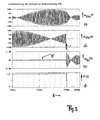
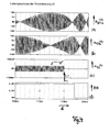
Signaldiagramme für das Ausführungsbeispiel werden im Folgenden erläutert. Sie sind in
Das im Beispiel konstant angenommene Prüfsignal ε ist moduliert durch die Trägerfrequenz vom Modulator 44 als amplitudenmäßig kleines Signal ε' bei u53 ersichtlich, hier in Beispiel mit einer kleinen Amplitude unter 200mV.The test signal ε, which is assumed to be constant in the example, is modulated by the carrier frequency from the
Für einen anzunehmenden Fehlerfall zeigen die
Das modulierte Prüfsignal ε' ist in beiden Fehlerfällen ersichtlich, in zwei unterschiedlichen Amplitudendarstellungen, vgl. jeweils das Diagramm (c) von
Nach Eintritt des Fehlerfalls zum Zeitpunkt tF schaltet das Fehlersignal F der Diagramme (f) als Ausgang des Fensterkomparators 38 auf (logisch) Null. Damit wird das Fehlersignal F zu einem zeitabhängigen Signal F(t), wenn die Zeit die unabhängige Größe ist. Der im Beispiel der
Die gezeigten Fehlersituation zeigen, dass sowohl Fehler im Stator, wie auch Fehler von Leitungen zum Stator, wie auch Fehler im Rotor oder in Leitungen vom Rotor erfasst werden. Dafür sorgt die Zuführung des Prüfsignals ε nicht nur zu der Schaltung 40, sondern auch zur Prüfschaltung 30, wo sie bei Wegfall des Signals nach
Der Tiefpass 32b als Bestandteil des Filters 32 mit der Betragsbildung 32a filtert Hochfrequenzanteile aus, welche (parallel) durch die Demodulation im Eingangsbereich 41 der Steueranordnung 40 herausgenommen werden. Diese Glättung 32b wirkt sich bei gegebenem Fensterkomparator 38 und vorgegebener Ansprechschwelle auf eine Zeitverzögerung aus, bis zum Ansprechen von F(t).The low-
Je größer der Signalausschlag ist, vgl.
Claims (29)
- A method for detecting undesired operating conditions of a drive or drive mechanism, wherein(a) a sensor (50), which is transformer coupled between a stator side and a rotor side, provides an operating signal (u53) to a control circuit (40) for detecting a position value or a rotational speed value of the drive, wherein the control circuit (40) executes a servo control (42, 49) for calculating and emitting at least one rotation speed value (ω) or position value from the operating signal (u53);(b) a safety monitoring device (30) for determining and emitting an error signal (F) is provided with a test signal (ε), which test signal is also provided to the control circuit (40);(c) the error signal (F) is emitted when an undesired operating condition occurs.
- The method according to claim 1, wherein the safety monitoring device (30) and the control circuit (40) are provided with the same operating signal (u53) of the transformer coupled sensor (50).
- The method according to claim 1, wherein the undesired operating condition is a short circuit in the area of the sensor (50) or its connecting leads.
- The method according to claim 1, wherein the test signal (ε) is substantially constant.
- The method according to claims 1 or 4, wherein the test signal is an angle signal.
- The method according to claims 1 or 5, wherein the test signal (ε) interferes at a point of the control circuit (40) located before at least one integrator (42, 43).
- The method according to claim 1, wherein the undesired operating condition is at least one of the following:(i) an excessive rotational speed;(ii) an exceeding of a predetermined limit speed;(iii) an electrical failure in the sensor (50);(iv) an electrical failure in the area of connections or lead paths of the sensor (50);(v) a mechanical failure in the area of the sensor (50).
- The method according to claim 1, wherein the sensor (50) is a signal generator for determining or calculating at least one operating signal of the drive technology at the drive mechanism.
- The method according to claim 8, wherein the sensor is configured as a synchro resolver or resolver.
- The method according to claim 2, wherein the safety monitoring device (30) influences (31, 32) the operating signal (u53) initially in a functionally similar manner as the control circuit (40), but separately thereof.
- The method according to claim 10, wherein the separate influencing is independent of a corresponding influencing in the control circuit (40).
- The method according to claim 10, wherein the separate influencing comprises an A/D conversion and a smoothing (32b) for suppressing a high-frequency portion (44) of the operating signal (u53).
- The method according to claim 12, wherein the influenced, smoothed operating signal is combined (33) with the test signal (ε) in a difference forming manner for obtaining a difference signal (u33).
- The method according to claim 13, wherein a tolerance range (Δu38) is compared with the difference signal (u33) for emitting the error signal (F;F(t)) when the difference signal leaves the tolerance range.
- The method according to claim 1, wherein the sensor (50) is mounted to a shaft of the drive for emitting the operating signal (u53) as an output signal of a transformer-induced winding (53) mechanically coupled to the shaft in a manner independent of the rotation of the shaft.
- The method according to claim 1, for detecting or identifying interference effects on the drive not detectable and adjustable by closed-loop control by means of the sensor (50), the output signal (u53) of which is used as an operating signal for closed-loop control of the drive, wherein(i) the operating signal (u53) as a useful signal and the test signal as an imbalance signal are provided to both, the control circuit (40) downstream of the sensor (50) and the monitoring circuit (30);(ii) the imbalance signal and the useful signal are subtractively combined (33) in the monitoring circuit;(iii) an error signal (F;F(t)) is substantially generated (38) when a compensation effected by the combination in the monitoring circuit (30, 33) is left.
- The method according to claim 16, wherein the useful signal is smoothed, in particular also rectified (32a) in the monitoring circuit (30) prior to subtractive combination thereof.
- The method according to claim 16, wherein the generation of the error signal (F) is temporarily blocked (38) via an amount-related or time-related threshold (Δu38).
- The method according to claim 16, wherein a low-frequency portion of the useful signal is subtractively combined (33) with the imbalance signal.
- The method according to claims 1 or 16, wherein the test signal as an imbalance signal (ε) is an at least continuous signal, in particular a constant value.
- The method according to claim 20, wherein the value is an angle or position variable (ε).
- The method according to claim 21, wherein the position variable, as an offset in the measured position value, is compensated prior to being passed on to a control of the drive.
- A sensor having a stator and a rotor for assembly to a drive shaft and for measuring rotational signals of a drive, such as rotational speed, acceleration or position (α,α,ϕ), wherein(1) a control circuit (40) including a servo control (42, 49) is provided, which feeds at least two windings (51a, 51b) of the sensor (50) via an actuating portion (49), or is configured for a corresponding feeding;(2) a further winding (53) rotatable relative to the stator is disposed on the rotor of the sensor (50) for emitting an operating signal (u53);(3) a separate monitoring circuit (30) is provided which, as well as the control circuit (40), can be provided with the operating signal for determining and emitting an error signal (F) when a compensation case is left.
- The sensor according to claim 23, wherein the control circuit (40) can be provided with an imbalance signal (ε), which permanently corrupts the measuring result of the sensor and can be filtered out, as a control signal (u32,u33), from the operating signal (u53) in the monitoring circuit (30).
- The sensor according to claim 24, wherein the imbalance signal (ε) can also be provided to the monitoring circuit (30) for comparing, in particular subtractively combining it with the filtered control signal.
- The sensor according to claim 23, wherein a frequency generator (44) is provided in the control circuit (40) for implementing at least one modulation of the output signals (u51b,u51a) of the control circuit (40) by use of a continuous signal, in particular a sinusoidal signal.
- The sensor according to claim 23, wherein the monitoring circuit (30) is separate from the control circuit (40).
- The sensor according to claim 23, wherein the monitoring circuit (30) is not disposed at the sensor (50).
- The sensor according to claim 23, wherein the control circuit including the servo control comprises at least one integral controller (43) - in particular a PI controller- to which a control deviation amounting to substantially zero in a stationary state can be provided.
Applications Claiming Priority (3)
| Application Number | Priority Date | Filing Date | Title |
|---|---|---|---|
| DE10305337 | 2003-02-10 | ||
| DE10305337 | 2003-02-10 | ||
| PCT/DE2004/000240 WO2004070924A2 (en) | 2003-02-10 | 2004-02-10 | Non-redundant safety monitoring for an electric drive mechanism (with a sensor) |
Publications (2)
| Publication Number | Publication Date |
|---|---|
| EP1593006A2 EP1593006A2 (en) | 2005-11-09 |
| EP1593006B1 true EP1593006B1 (en) | 2014-11-19 |
Family
ID=32841624
Family Applications (1)
| Application Number | Title | Priority Date | Filing Date |
|---|---|---|---|
| EP04709579.9A Expired - Lifetime EP1593006B1 (en) | 2003-02-10 | 2004-02-10 | Non-redundant safety monitoring for an electric drive mechanism (with a sensor) |
Country Status (5)
| Country | Link |
|---|---|
| US (1) | US7723940B2 (en) |
| EP (1) | EP1593006B1 (en) |
| CN (2) | CN100559308C (en) |
| DE (1) | DE112004000326D2 (en) |
| WO (1) | WO2004070924A2 (en) |
Families Citing this family (13)
| Publication number | Priority date | Publication date | Assignee | Title |
|---|---|---|---|---|
| US7558655B2 (en) * | 2004-09-10 | 2009-07-07 | Ford Global Technologies, Llc | Prognostic method and system for hybrid and electric vehicle components |
| DE102007034060B4 (en) * | 2007-07-20 | 2012-11-08 | Siemens Ag | Actuator for an on / off valve |
| DE102008024527A1 (en) | 2008-05-25 | 2009-11-26 | Lenze Automation Gmbh | Method and device for monitoring a rotational angle sensor |
| US8198841B2 (en) * | 2009-08-19 | 2012-06-12 | GM Global Technology Operations LLC | Method and circuit for processing a resolver fault |
| DE102009046925A1 (en) | 2009-11-20 | 2011-05-26 | Lenze Automation Gmbh | A method, apparatus and system for monitoring the determination of a rotor angle of a rotating shaft by means of a resolver |
| DE102010038638B4 (en) | 2010-07-29 | 2019-02-21 | Lenze Automation Gmbh | A method, apparatus and system for monitoring the determination of a rotor angle of a rotating shaft by means of a resolver |
| DE102010047269B4 (en) * | 2010-10-01 | 2014-07-17 | Diehl Aerospace Gmbh | Circuit arrangement and method for monitoring a DSP in the context of a safety-critical application |
| JP6207223B2 (en) * | 2013-05-01 | 2017-10-04 | キヤノン株式会社 | Motor drive device and control method thereof |
| DE102014103688A1 (en) * | 2014-03-18 | 2015-09-24 | Khs Gmbh | Device and method for error detection in machines |
| KR101619593B1 (en) | 2014-07-08 | 2016-05-10 | 현대자동차주식회사 | Method for judging failure in resolver |
| US9528857B2 (en) * | 2014-10-17 | 2016-12-27 | Infineon Technologies Ag | Time capture based resolver to digital converter |
| DE102018100878A1 (en) * | 2018-01-16 | 2019-07-18 | Ebm-Papst Landshut Gmbh | Method for checking a time-discrete signal value of a sensor for freedom from errors |
| CN108958019B (en) * | 2018-08-21 | 2024-03-22 | 深圳市多恩技术有限公司 | Safety adapter, serial safety control loop and safety control method |
Family Cites Families (18)
| Publication number | Priority date | Publication date | Assignee | Title |
|---|---|---|---|---|
| CH682351A5 (en) * | 1986-10-16 | 1993-08-31 | Sohard Ag | |
| DE3834384A1 (en) | 1988-10-10 | 1990-04-12 | Lenze Gmbh & Co Kg Aerzen | METHOD AND CIRCUIT ARRANGEMENT FOR GENERATING DIGITAL SPEED AND ROTARY ANGLE INFORMATION BY MEANS OF A FUNCTION TERMINAL |
| US5635810A (en) * | 1995-09-20 | 1997-06-03 | Analog Devices, Inc. | Control system for a permanent magnet synchronous motor |
| DE59706479D1 (en) * | 1996-07-25 | 2002-04-04 | Lust Antriebstechnik Gmbh | Arrangement and method for operating a magnetically levitated, electromotive drive device in the event of a network fault |
| DE19635040C1 (en) | 1996-08-29 | 1998-01-15 | Litton Precision Prod Int | Functional rotary resolver for generating signals with reduced harmonics e.g resolver or synchro for servo applications |
| US6199422B1 (en) * | 1997-07-29 | 2001-03-13 | Skf Condition Monitoring, Inc. | Method and system for fast probe failure determination |
| JP5062925B2 (en) * | 1997-12-06 | 2012-10-31 | エラン・シャルトエレメンテ・ゲーエムベーハー・ウント・コンパニー・カーゲー | Monitoring and control equipment for technical equipment |
| DE19816046A1 (en) * | 1998-04-09 | 1999-10-28 | Bosch Gmbh Robert | Safety device for a drive |
| JP2000074694A (en) * | 1998-08-27 | 2000-03-14 | Hitachi Ltd | Method and apparatus for detecting abnormality of rotation sensor |
| DE19908230A1 (en) * | 1999-02-25 | 2000-08-31 | Heidelberger Druckmasch Ag | Device for monitoring safety-related processes on machines |
| WO2001011747A1 (en) * | 1999-08-07 | 2001-02-15 | Robert Bosch Gmbh | Device for monitoring the measuring system of an electric drive |
| DE10011410A1 (en) * | 2000-03-09 | 2001-09-20 | Bosch Gmbh Robert | Fail-safe signal generation device for safety critical signal has back-up device for generation of load driver signal in emergency operating mode |
| JP2002310727A (en) * | 2001-04-13 | 2002-10-23 | Mitsubishi Electric Corp | Abnormality detecting device and method for position detecting device |
| EP1253490B1 (en) * | 2001-04-25 | 2011-08-17 | Siemens Aktiengesellschaft | Method and device for secure speed monitoring |
| JP3630410B2 (en) * | 2001-05-22 | 2005-03-16 | 三菱電機株式会社 | Position detection apparatus and abnormality detection apparatus |
| JP3758563B2 (en) * | 2001-12-04 | 2006-03-22 | 豊田工機株式会社 | Position detector correction method and electric power steering apparatus |
| JP3812739B2 (en) * | 2002-05-28 | 2006-08-23 | 三菱電機株式会社 | Motor abnormality detection device and electric power steering control device |
| JP2006023164A (en) * | 2004-07-07 | 2006-01-26 | Mitsubishi Electric Corp | Resolver fault diagnosis circuit |
-
2004
- 2004-02-10 EP EP04709579.9A patent/EP1593006B1/en not_active Expired - Lifetime
- 2004-02-10 WO PCT/DE2004/000240 patent/WO2004070924A2/en not_active Ceased
- 2004-02-10 US US10/544,931 patent/US7723940B2/en not_active Expired - Lifetime
- 2004-02-10 DE DE112004000326T patent/DE112004000326D2/en not_active Withdrawn - After Issue
- 2004-02-10 CN CNB2004800039256A patent/CN100559308C/en not_active Expired - Fee Related
- 2004-02-10 CN CNA2008101343643A patent/CN101334633A/en active Pending
Also Published As
| Publication number | Publication date |
|---|---|
| WO2004070924A2 (en) | 2004-08-19 |
| US7723940B2 (en) | 2010-05-25 |
| DE112004000326D2 (en) | 2005-11-24 |
| CN101334633A (en) | 2008-12-31 |
| EP1593006A2 (en) | 2005-11-09 |
| US20060186891A1 (en) | 2006-08-24 |
| CN1748186A (en) | 2006-03-15 |
| WO2004070924A3 (en) | 2004-11-25 |
| CN100559308C (en) | 2009-11-11 |
Similar Documents
| Publication | Publication Date | Title |
|---|---|---|
| EP1593006B1 (en) | Non-redundant safety monitoring for an electric drive mechanism (with a sensor) | |
| DE2926378C2 (en) | Circuit arrangement for restarting a delayed induction motor | |
| EP2309641B1 (en) | Method and device for error-free monitoring of an electric motor drive | |
| DE69805641T2 (en) | DEVICE AND METHOD FOR CONTROLLING A SYNCHRONOUS MOTOR WITH PERMANENT MAGNET | |
| EP2460056B1 (en) | Method and device for monitoring a motion quantity on an electric drive in an error-proof manner | |
| DE4330823C2 (en) | Drive device with a safety device for special operation | |
| EP2132440B1 (en) | Drive device for driving several axles | |
| DE112020000915T5 (en) | Motor control device and electric brake device using it, and motor control method and electric brake control method using it | |
| DE102015226382A1 (en) | Method and arrangement for monitoring a PSM machine | |
| DE102018132413A1 (en) | Method for detecting different vibrations in a wind turbine | |
| DE102016100680A1 (en) | Wind turbine | |
| DE102010051873B4 (en) | Integrated circuit arrangement and method for signal monitoring | |
| EP2746732B2 (en) | Transducer device and method for determining a position | |
| WO2004005939A1 (en) | Device for determining the rotational speed of a rotating machine part | |
| DE3424247C2 (en) | ||
| EP1589653A2 (en) | Device for driving a synchronous motor | |
| DE102013204600A1 (en) | Wind turbine with frequency measurement | |
| DE102015003499B4 (en) | Multiturn encoder with increased security requirements | |
| DE2744941A1 (en) | PROCEDURE AND EQUIPMENT FOR MONITORING A POSITIONER FOR FAULTS | |
| DE3926705A1 (en) | ARRANGEMENT AND DEVICE FOR REGULATING A GAS TURBINE ENGINE | |
| EP3895303A1 (en) | Method for monitoring a drive system, and drive system | |
| DE102016121488B4 (en) | METHOD FOR DETECTING A ROTOR POSITION ANGLE IN AN ELECTRICAL MACHINE AND CONTROL SYSTEM THEREFOR AND DRIVE SYSTEM EQUIPPED THEREWITH | |
| DE102021105352A1 (en) | Sensor, in particular torque or angle of rotation sensor | |
| EP4163739B1 (en) | Method for monitoring an electrical switching assembly | |
| DE202020107063U1 (en) | Multiturn rotary encoder |
Legal Events
| Date | Code | Title | Description |
|---|---|---|---|
| PUAI | Public reference made under article 153(3) epc to a published international application that has entered the european phase |
Free format text: ORIGINAL CODE: 0009012 |
|
| 17P | Request for examination filed |
Effective date: 20050715 |
|
| AK | Designated contracting states |
Kind code of ref document: A2 Designated state(s): AT BE BG CH CY CZ DE DK EE ES FI FR GB GR HU IE IT LI LU MC NL PT RO SE SI SK TR |
|
| AX | Request for extension of the european patent |
Extension state: AL LT LV MK |
|
| DAX | Request for extension of the european patent (deleted) | ||
| RAP1 | Party data changed (applicant data changed or rights of an application transferred) |
Owner name: LENZE AUTOMATION GMBH |
|
| 17Q | First examination report despatched |
Effective date: 20100113 |
|
| GRAP | Despatch of communication of intention to grant a patent |
Free format text: ORIGINAL CODE: EPIDOSNIGR1 |
|
| INTG | Intention to grant announced |
Effective date: 20140717 |
|
| GRAS | Grant fee paid |
Free format text: ORIGINAL CODE: EPIDOSNIGR3 |
|
| GRAA | (expected) grant |
Free format text: ORIGINAL CODE: 0009210 |
|
| RAP1 | Party data changed (applicant data changed or rights of an application transferred) |
Owner name: LENZE AUTOMATION GMBH |
|
| AK | Designated contracting states |
Kind code of ref document: B1 Designated state(s): AT BE BG CH CY CZ DE DK EE ES FI FR GB GR HU IE IT LI LU MC NL PT RO SE SI SK TR |
|
| REG | Reference to a national code |
Ref country code: GB Ref legal event code: FG4D Free format text: NOT ENGLISH |
|
| REG | Reference to a national code |
Ref country code: CH Ref legal event code: EP |
|
| REG | Reference to a national code |
Ref country code: AT Ref legal event code: REF Ref document number: 697359 Country of ref document: AT Kind code of ref document: T Effective date: 20141215 |
|
| REG | Reference to a national code |
Ref country code: IE Ref legal event code: FG4D Free format text: LANGUAGE OF EP DOCUMENT: GERMAN |
|
| REG | Reference to a national code |
Ref country code: DE Ref legal event code: R096 Ref document number: 502004014767 Country of ref document: DE Effective date: 20141231 |
|
| REG | Reference to a national code |
Ref country code: NL Ref legal event code: VDEP Effective date: 20141119 |
|
| PG25 | Lapsed in a contracting state [announced via postgrant information from national office to epo] |
Ref country code: ES Free format text: LAPSE BECAUSE OF FAILURE TO SUBMIT A TRANSLATION OF THE DESCRIPTION OR TO PAY THE FEE WITHIN THE PRESCRIBED TIME-LIMIT Effective date: 20141119 Ref country code: FI Free format text: LAPSE BECAUSE OF FAILURE TO SUBMIT A TRANSLATION OF THE DESCRIPTION OR TO PAY THE FEE WITHIN THE PRESCRIBED TIME-LIMIT Effective date: 20141119 Ref country code: NL Free format text: LAPSE BECAUSE OF FAILURE TO SUBMIT A TRANSLATION OF THE DESCRIPTION OR TO PAY THE FEE WITHIN THE PRESCRIBED TIME-LIMIT Effective date: 20141119 Ref country code: PT Free format text: LAPSE BECAUSE OF FAILURE TO SUBMIT A TRANSLATION OF THE DESCRIPTION OR TO PAY THE FEE WITHIN THE PRESCRIBED TIME-LIMIT Effective date: 20150319 |
|
| PG25 | Lapsed in a contracting state [announced via postgrant information from national office to epo] |
Ref country code: SE Free format text: LAPSE BECAUSE OF FAILURE TO SUBMIT A TRANSLATION OF THE DESCRIPTION OR TO PAY THE FEE WITHIN THE PRESCRIBED TIME-LIMIT Effective date: 20141119 Ref country code: GR Free format text: LAPSE BECAUSE OF FAILURE TO SUBMIT A TRANSLATION OF THE DESCRIPTION OR TO PAY THE FEE WITHIN THE PRESCRIBED TIME-LIMIT Effective date: 20150220 Ref country code: CY Free format text: LAPSE BECAUSE OF FAILURE TO SUBMIT A TRANSLATION OF THE DESCRIPTION OR TO PAY THE FEE WITHIN THE PRESCRIBED TIME-LIMIT Effective date: 20141119 |
|
| PG25 | Lapsed in a contracting state [announced via postgrant information from national office to epo] |
Ref country code: SK Free format text: LAPSE BECAUSE OF FAILURE TO SUBMIT A TRANSLATION OF THE DESCRIPTION OR TO PAY THE FEE WITHIN THE PRESCRIBED TIME-LIMIT Effective date: 20141119 Ref country code: CZ Free format text: LAPSE BECAUSE OF FAILURE TO SUBMIT A TRANSLATION OF THE DESCRIPTION OR TO PAY THE FEE WITHIN THE PRESCRIBED TIME-LIMIT Effective date: 20141119 Ref country code: EE Free format text: LAPSE BECAUSE OF FAILURE TO SUBMIT A TRANSLATION OF THE DESCRIPTION OR TO PAY THE FEE WITHIN THE PRESCRIBED TIME-LIMIT Effective date: 20141119 Ref country code: RO Free format text: LAPSE BECAUSE OF FAILURE TO SUBMIT A TRANSLATION OF THE DESCRIPTION OR TO PAY THE FEE WITHIN THE PRESCRIBED TIME-LIMIT Effective date: 20141119 Ref country code: DK Free format text: LAPSE BECAUSE OF FAILURE TO SUBMIT A TRANSLATION OF THE DESCRIPTION OR TO PAY THE FEE WITHIN THE PRESCRIBED TIME-LIMIT Effective date: 20141119 |
|
| REG | Reference to a national code |
Ref country code: DE Ref legal event code: R097 Ref document number: 502004014767 Country of ref document: DE |
|
| PLBE | No opposition filed within time limit |
Free format text: ORIGINAL CODE: 0009261 |
|
| STAA | Information on the status of an ep patent application or granted ep patent |
Free format text: STATUS: NO OPPOSITION FILED WITHIN TIME LIMIT |
|
| PG25 | Lapsed in a contracting state [announced via postgrant information from national office to epo] |
Ref country code: LU Free format text: LAPSE BECAUSE OF FAILURE TO SUBMIT A TRANSLATION OF THE DESCRIPTION OR TO PAY THE FEE WITHIN THE PRESCRIBED TIME-LIMIT Effective date: 20150210 |
|
| REG | Reference to a national code |
Ref country code: CH Ref legal event code: PL |
|
| 26N | No opposition filed |
Effective date: 20150820 |
|
| GBPC | Gb: european patent ceased through non-payment of renewal fee |
Effective date: 20150219 |
|
| PG25 | Lapsed in a contracting state [announced via postgrant information from national office to epo] |
Ref country code: MC Free format text: LAPSE BECAUSE OF FAILURE TO SUBMIT A TRANSLATION OF THE DESCRIPTION OR TO PAY THE FEE WITHIN THE PRESCRIBED TIME-LIMIT Effective date: 20141119 Ref country code: LI Free format text: LAPSE BECAUSE OF NON-PAYMENT OF DUE FEES Effective date: 20150228 Ref country code: CH Free format text: LAPSE BECAUSE OF NON-PAYMENT OF DUE FEES Effective date: 20150228 |
|
| REG | Reference to a national code |
Ref country code: IE Ref legal event code: MM4A |
|
| REG | Reference to a national code |
Ref country code: FR Ref legal event code: ST Effective date: 20151030 |
|
| PG25 | Lapsed in a contracting state [announced via postgrant information from national office to epo] |
Ref country code: IT Free format text: LAPSE BECAUSE OF FAILURE TO SUBMIT A TRANSLATION OF THE DESCRIPTION OR TO PAY THE FEE WITHIN THE PRESCRIBED TIME-LIMIT Effective date: 20141119 |
|
| PG25 | Lapsed in a contracting state [announced via postgrant information from national office to epo] |
Ref country code: GB Free format text: LAPSE BECAUSE OF NON-PAYMENT OF DUE FEES Effective date: 20150219 Ref country code: IE Free format text: LAPSE BECAUSE OF NON-PAYMENT OF DUE FEES Effective date: 20150210 |
|
| PG25 | Lapsed in a contracting state [announced via postgrant information from national office to epo] |
Ref country code: FR Free format text: LAPSE BECAUSE OF NON-PAYMENT OF DUE FEES Effective date: 20150302 Ref country code: SI Free format text: LAPSE BECAUSE OF FAILURE TO SUBMIT A TRANSLATION OF THE DESCRIPTION OR TO PAY THE FEE WITHIN THE PRESCRIBED TIME-LIMIT Effective date: 20141119 |
|
| REG | Reference to a national code |
Ref country code: AT Ref legal event code: MM01 Ref document number: 697359 Country of ref document: AT Kind code of ref document: T Effective date: 20150210 |
|
| PG25 | Lapsed in a contracting state [announced via postgrant information from national office to epo] |
Ref country code: AT Free format text: LAPSE BECAUSE OF NON-PAYMENT OF DUE FEES Effective date: 20150210 |
|
| PG25 | Lapsed in a contracting state [announced via postgrant information from national office to epo] |
Ref country code: BG Free format text: LAPSE BECAUSE OF FAILURE TO SUBMIT A TRANSLATION OF THE DESCRIPTION OR TO PAY THE FEE WITHIN THE PRESCRIBED TIME-LIMIT Effective date: 20141119 Ref country code: HU Free format text: LAPSE BECAUSE OF FAILURE TO SUBMIT A TRANSLATION OF THE DESCRIPTION OR TO PAY THE FEE WITHIN THE PRESCRIBED TIME-LIMIT; INVALID AB INITIO Effective date: 20040210 |
|
| PG25 | Lapsed in a contracting state [announced via postgrant information from national office to epo] |
Ref country code: BE Free format text: LAPSE BECAUSE OF NON-PAYMENT OF DUE FEES Effective date: 20150228 |
|
| PG25 | Lapsed in a contracting state [announced via postgrant information from national office to epo] |
Ref country code: TR Free format text: LAPSE BECAUSE OF FAILURE TO SUBMIT A TRANSLATION OF THE DESCRIPTION OR TO PAY THE FEE WITHIN THE PRESCRIBED TIME-LIMIT Effective date: 20141119 |
|
| PGFP | Annual fee paid to national office [announced via postgrant information from national office to epo] |
Ref country code: DE Payment date: 20190429 Year of fee payment: 16 |
|
| REG | Reference to a national code |
Ref country code: DE Ref legal event code: R119 Ref document number: 502004014767 Country of ref document: DE |
|
| PG25 | Lapsed in a contracting state [announced via postgrant information from national office to epo] |
Ref country code: DE Free format text: LAPSE BECAUSE OF NON-PAYMENT OF DUE FEES Effective date: 20200901 |