EP1589653A2 - Device for driving a synchronous motor - Google Patents
Device for driving a synchronous motor Download PDFInfo
- Publication number
- EP1589653A2 EP1589653A2 EP05008015A EP05008015A EP1589653A2 EP 1589653 A2 EP1589653 A2 EP 1589653A2 EP 05008015 A EP05008015 A EP 05008015A EP 05008015 A EP05008015 A EP 05008015A EP 1589653 A2 EP1589653 A2 EP 1589653A2
- Authority
- EP
- European Patent Office
- Prior art keywords
- synchronous motor
- speed
- function module
- controller
- unit
- Prior art date
- Legal status (The legal status is an assumption and is not a legal conclusion. Google has not performed a legal analysis and makes no representation as to the accuracy of the status listed.)
- Withdrawn
Links
Images
Classifications
-
- H—ELECTRICITY
- H02—GENERATION; CONVERSION OR DISTRIBUTION OF ELECTRIC POWER
- H02P—CONTROL OR REGULATION OF ELECTRIC MOTORS, ELECTRIC GENERATORS OR DYNAMO-ELECTRIC CONVERTERS; CONTROLLING TRANSFORMERS, REACTORS OR CHOKE COILS
- H02P6/00—Arrangements for controlling synchronous motors or other dynamo-electric motors using electronic commutation dependent on the rotor position; Electronic commutators therefor
- H02P6/24—Arrangements for stopping
-
- H—ELECTRICITY
- H02—GENERATION; CONVERSION OR DISTRIBUTION OF ELECTRIC POWER
- H02P—CONTROL OR REGULATION OF ELECTRIC MOTORS, ELECTRIC GENERATORS OR DYNAMO-ELECTRIC CONVERTERS; CONTROLLING TRANSFORMERS, REACTORS OR CHOKE COILS
- H02P29/00—Arrangements for regulating or controlling electric motors, appropriate for both AC and DC motors
- H02P29/10—Arrangements for regulating or controlling electric motors, appropriate for both AC and DC motors for preventing overspeed or under speed
-
- H—ELECTRICITY
- H02—GENERATION; CONVERSION OR DISTRIBUTION OF ELECTRIC POWER
- H02P—CONTROL OR REGULATION OF ELECTRIC MOTORS, ELECTRIC GENERATORS OR DYNAMO-ELECTRIC CONVERTERS; CONTROLLING TRANSFORMERS, REACTORS OR CHOKE COILS
- H02P6/00—Arrangements for controlling synchronous motors or other dynamo-electric motors using electronic commutation dependent on the rotor position; Electronic commutators therefor
- H02P6/06—Arrangements for speed regulation of a single motor wherein the motor speed is measured and compared with a given physical value so as to adjust the motor speed
-
- H—ELECTRICITY
- H02—GENERATION; CONVERSION OR DISTRIBUTION OF ELECTRIC POWER
- H02P—CONTROL OR REGULATION OF ELECTRIC MOTORS, ELECTRIC GENERATORS OR DYNAMO-ELECTRIC CONVERTERS; CONTROLLING TRANSFORMERS, REACTORS OR CHOKE COILS
- H02P6/00—Arrangements for controlling synchronous motors or other dynamo-electric motors using electronic commutation dependent on the rotor position; Electronic commutators therefor
- H02P6/14—Electronic commutators
- H02P6/16—Circuit arrangements for detecting position
- H02P6/17—Circuit arrangements for detecting position and for generating speed information
Definitions
- the invention relates to a device for operating a synchronous motor.
- Such synchronous motors in particular as servo or stepper motors can be designed as drives of machinery and equipment in used in various industrial applications.
- the synchronous motors form permanent-magnet electric machines, especially as stepper motors or servomotors can be formed.
- Such synchronous motors operated with position controls include a sensor in Form of at least one encoder, by means of which a position determination of the synchronous motor is carried out.
- the encoder (s) record the current one Positions of primary parts, which are used to generate magnetic fields are passed through predetermined currents, relative to the positions of magnetic secondary parts.
- Stepper motors by means of the sensor, the determination of the current Actual position of the rotor.
- the position of the synchronous motor controlled Become accordingly in linear motors by means of a sensor, the positions of runners on assigned coils determined and regulated.
- a device in which the synchronous motor is operated in a normal mode, in which the signals at least a sensor used for position control of the synchronous motor become. Furthermore, the synchronous motor can be switched to run-flat operation, in which the synchronous motor in a step operation and / or with a sensorless position control is operated.
- the availability of the Synchronous motor can be increased significantly.
- the sensor-controlled position control in normal operation preferably only used if the encoder has no defect. Once a defect or generally unsafe Operation of the encoder is present, preferably automatically switching over on the emergency operation, in which the synchronous motor without external sensors, that is operated without encoder.
- the device thus formed is in safety applications not applicable, since the device is not in a controlled safe state passes.
- the invention has for its object a device of the aforementioned Form such a way that these safety applications can be used.
- the device according to the invention serves to operate a synchronous motor, synonymous with the term synchronous motor in addition to permanently excited motors also Reluctance motors are included.
- the device has a first monitoring unit in which in order to generate a first control signal in dependence the measured values of a sensor the compliance with a limit value the speed of the synchronous motor is checked.
- the Device according to the invention a second monitoring unit, in which compliance with a limit value of the commutation angle of the synchronous motor or whose time change is checked.
- At least a switching unit is the synchronous motor for compliance with the limits in Dependence of the control signals activated.
- the device according to the invention a two-channel, redundant structure. This will be a cyclic Error control of the synchronous motor allows, so that the device in safety-relevant applications can be used.
- monitoring units Depending on the required level of security is expediently a mutual Monitoring the monitoring units. To do this, they control themselves Monitoring units in terms of their functions cyclically.
- each of one of the monitoring units to be controlled is preferably formed by the external control is dependent on the Measured values of a sensor detects the speed of the synchronous motor.
- the preferred one in the amplifier integrated function module for controlling the synchronous motor is formed, the commutation of the synchronous motor is monitored.
- the invention is based on the knowledge that by a limitation the commutation of the synchronous motor safe compliance with a limit speed the synchronous motor and in particular a secure hold of the synchronous motor can be guaranteed. This can be hazards, the consequences the force effects of the engine are prevented.
- the swept commutation angle is per unit of time a measure of the direction and speed of the rotor relative to the stator or generally a primary part relative to a secondary part.
- the device according to the invention used for safe monitoring of range limits of the synchronous motor become.
- the maximum travels of the synchronous motor are in positive and negative direction relative to a reference position as parameter values stored redundantly in the monitoring units.
- the device is then used by the monitoring functions of the monitoring units the synchronous motor operated at a safe speed, so that the plant is retracted to the reference position by signals is defined by switches, absolute encoders or the like.
- the reference position is then passed as a parameter value to the monitoring units. Then the monitoring takes place continuously in the monitoring units compliance with the range limits relative to the reference position.
- the device according to the invention is generally for synchronous motors with a can be used linear and a rotary structure.
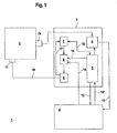
- Figure 1 shows schematically the structure of a device 1 for operating a Synchronous motor 2.
- the synchronous motor 2 is in the present case as rotative Drive formed with a rotor and stator.
- the device 1 comprises an amplifier unit 3 for controlling the synchronous motor 2 and an external control 4, by means of which the operation of the Synchronous motor 2 is controllable.
- the controller 4 may, for example, a PLC control or a CNC control.
- the amplifier unit 3 comprises a central unit 5, which acts as a microprocessor or the like may be formed. To this central unit 5 are a Evaluation circuit 6, a function module 7 and a relay assembly 8, the is performed on a power amplifier 9, connected.
- the evaluation circuit 6 measured values generated in a sensor 2a are measured evaluated.
- the evaluation circuit 6 preferably consists of an ASIC or FPGA.
- the encoder 2 a is arranged on the synchronous motor 2 and in the present Case as incremental encoder for determining the speed of the synchronous motor 2 trained.
- the encoder 2a as an absolute encoder, Resolver, half-sensor or the like may be formed.
- the functional module 7 is preferably designed as an ASIC or FPGA and forms a drive stage for the synchronous motor 2.
- the function module 7 as well as the evaluation circuit 6 of discrete electronic components and a microcontroller.
- the Current control of the synchronous motor performed.
- the relay assembly 8 consists of at least two series connected, independently switchable switching elements, preferably of relays special Design, in particular of safety relays with forced operation formed are.
- the controller 4 acts on at least one of the switching elements, the central unit 5 on at least one other switching element.
- the operation of a Switching element prevents the control of the power output stage 9 such that the emergence of a rotation of the field of rotation of the synchronous motor 2 generating is suppressed and / or the power supply of the power amplifier is prevented.
- the power output stage 9 is connected via a line 10 to a coil 11 of the synchronous motor 2 connected.
- the controller 4 is via bidirectional leads 12, 12 ⁇ to the controller. 4 connected.
- the registered in the evaluation circuit 6 actual positions of the synchronous motor 2 are read via a line 13 in the controller 4
- the controller 4 gives setpoints for the Operation of the synchronous motor 2, which implemented by the function module 7 become.
- the function module 7 controls the power output stage 9 in a suitable Way.
- the controller 4 transmits via the central unit 5 a setpoint torque with amount and direction to the function module 7th
- the controller 4 takes over the function of a first monitoring unit.
- the monitoring units are over the bidirectional Supply lines 12, 12 'between the central unit 5 and controller 4 coupled.
- the data is exchanged via the bidirectional Supply lines 12, 12 'a mutual monitoring of the monitoring units.
- having a predetermined level of security Device 1 is the speed by means of the first monitoring unit of the synchronous motor 2 as a function of the measured values of the encoder 2a regulated.
- a safe limit of the synchronous motor 2 are performed, is in the Control 4 as the first monitoring unit, the speed to the specified Limit regulated.
- the regulation takes place in dependence of the differentiated Measured values of the encoder 2a.
- the function module 7 as the second monitoring unit the Commutation of the synchronous motor 2 according to the stored limit value limited.
- the change of the commutation angle per unit time which is a measure of the speed of the rotor of the synchronous motor 2 forms, by means of the function module 7 to a corresponding Value limited.
- the relay assembly 8 to exceed the Limit value of the speed of the synchronous motor 2 to prevent.
- the power supply to the power output stage 9 is suppressed and / or the control the power output stage 9 is interrupted, so that the emergence a rotation field generating the movement of the synchronous motor 2 prevented becomes.
- the power output stage 9 driven by the function module 7, so that the synchronous motor 2 expires accordingly.
- the monitoring units thus control the power output stage 9 and the relay arrangement 8 as independent switch units for limiting the motor speed in the form that the emergence of a movement of the Synchronous motor 2 generating rotating field is suppressed.
- the form Monitoring units independent diversified units to limit the Engine speed.
- the function module 7 checks in this case the amount of the commutation angle and sets it to a motor speed limit Value.
- the synchronous motor 2 of the device 1 similar to a stepper motor operated.
- the controller transmits 4 a target speed with magnitude and sign to the function module 7, which then the synchronous motor 2 via the power output stage 9 accordingly controls.
- a constant current for the Synchronous motor 2 predetermined.
- the speed of the synchronous motor 2 is in turn via the controller 4 regulated as a function of the measured values of the encoder 2a.
- the limit for safe compliance with a limit speed is again in both monitoring units, that is in the controller 4 and in the Function module 7, deposited.
- the function module 7 If it is detected in the function module 7 that the limit value is exceeded, this disables independent of the signals of the controller 4, the power amplifier 9 and deactivated in particular by the control in the 4th performed speed control.
- the function module 7 in case of interruption of the speed control of the controller 4 send out an error message. As soon as the controller 4 registers the error has, this turns off the relay assembly 8, so that not only the function module 7, but also the controller 4 the synchronous motor 2 in the safe Condition convicted.
Landscapes
- Engineering & Computer Science (AREA)
- Power Engineering (AREA)
- Control Of Motors That Do Not Use Commutators (AREA)
- Control Of Ac Motors In General (AREA)
Abstract
Description
Die Erfindung betrifft eine Vorrichtung zum Betrieb eines Synchronmotors.The invention relates to a device for operating a synchronous motor.
Derartige Synchronmotoren, die insbesondere als Servo- oder Schrittmotoren ausgebildet sein können, werden als Antriebe von Maschinen und Anlagen in unterschiedlichen industriellen Applikationen eingesetzt. Die Synchronmotoren bilden permanenterregte elektrische Maschinen, die insbesondere als Schrittmotoren oder Servomotoren ausgebildet sein können.Such synchronous motors, in particular as servo or stepper motors can be designed as drives of machinery and equipment in used in various industrial applications. The synchronous motors form permanent-magnet electric machines, especially as stepper motors or servomotors can be formed.
Zur Erzielung einer hohen Positioniergenauigkeit werden derartige Synchronmotoren mit Positionsregelungen betrieben. Diese umfassen eine Sensorik in Form wenigstens eines Messgebers, mittels derer eine Lageermittlung des Synchronmotors durchgeführt wird. Der oder die Messgeber erfassen dabei die aktuellen Positionen von Primärteilen, welche zur Erzeugung von Magnetfeldern von vorgegebenen Strömen durchflossen sind, relativ zu den Positionen von magnetischen Sekundärteilen. Bei rotativen Synchronmotoren, insbesondere Schrittmotoren, erfolgt mittels der Sensorik die Bestimmung der aktuellen Istposition des Rotors. In Abhängigkeit der Signale dieser Sensorik wird in einem Regelkreis die Position des Synchronmotors geregelt. Entsprechend werden bei Linearmotoren mittels einer Sensorik die Positionen von Läufern über zugeordnete Spulen ermittelt und geregelt.To achieve a high positioning accuracy such synchronous motors operated with position controls. These include a sensor in Form of at least one encoder, by means of which a position determination of the synchronous motor is carried out. The encoder (s) record the current one Positions of primary parts, which are used to generate magnetic fields are passed through predetermined currents, relative to the positions of magnetic secondary parts. In rotary synchronous motors, in particular Stepper motors, by means of the sensor, the determination of the current Actual position of the rotor. Depending on the signals of this sensor is in a Control loop, the position of the synchronous motor controlled. Become accordingly in linear motors by means of a sensor, the positions of runners on assigned coils determined and regulated.
Mit derartigen positionsgeregelten Synchronmotoren können Produktionsabläufe in Maschinen und Anlagen mit hoher Präzision und Reproduzierbarkeit gesteuert werden. Insbesondere als Servomotoren ausgebildete Synchronmotoren weisen zudem eine hohe Dynamik auf, wodurch besonders hohe Produktivitäten der Maschinen und Anlagen erzielt werden können. With such position-controlled synchronous motors production processes controlled in machines and plants with high precision and reproducibility become. In particular, designed as servomotors synchronous motors In addition, they have a high level of dynamics, resulting in particularly high productivities of the machinery and equipment can be achieved.
Nachteilig bei derartigen Synchronmotoren ist jedoch, dass aufgrund deren relativ aufwändigen Aufbaus die Ausfallwahrscheinhchkeiten relativ hoch sind. Insbesondere stellt die Sensorik zur Positionsregelung einen Risikofaktor dar. Ein Defekt in der Sensorik führt zu einem Ausfall des Synchronmotors und damit zu Produktionsausfällen in den mit dem Synchronmotor gesteuerten Anlagen.The disadvantage of such synchronous motors, however, that due to their relative complex construction the Ausfallwahrscheinhchkeiten are relatively high. Especially the sensor for position control is a risk factor Defect in the sensor leads to a failure of the synchronous motor and thus to Production losses in the systems controlled by the synchronous motor.
Aus der DE 102 07 549 A1 ist eine Vorrichtung bekannt, bei welcher der Synchronmotor in einem Normalbetrieb betrieben wird, in welchem die Signale wenigstens eines Messgebers zur Positionsregelung des Synchronmotors verwendet werden. Weiterhin ist der Synchronmotor in einen Notlaufbetrieb umschaltbar, in welchem der Synchronmotor in einem Schrittbetrieb und/oder mit einer sensorlosen Positionsregelung betrieben wird.From DE 102 07 549 A1 a device is known in which the synchronous motor is operated in a normal mode, in which the signals at least a sensor used for position control of the synchronous motor become. Furthermore, the synchronous motor can be switched to run-flat operation, in which the synchronous motor in a step operation and / or with a sensorless position control is operated.
Mit dieser Umschaltmöglichkeit der Betriebsart kann die Verfügbarkeit des Synchronmotors erheblich erhöht werden. Dabei wird die sensorgesteuerte Positionsregelung im Normalbetrieb vorzugsweise nur eingesetzt, falls der Messgeber keinen Defekt aufweist. Sobald ein Defekt oder allgemein ein unsicherer Betrieb des Messgebers vorliegt, erfolgt vorzugsweise selbsttätig ein Umschalten auf den Notlaufbetrieb, in welchem der Synchronmotor ohne externe Sensorik, das heißt ohne Messgeber betrieben wird.With this possibility of switching the operating mode, the availability of the Synchronous motor can be increased significantly. In this case, the sensor-controlled position control in normal operation preferably only used if the encoder has no defect. Once a defect or generally unsafe Operation of the encoder is present, preferably automatically switching over on the emergency operation, in which the synchronous motor without external sensors, that is operated without encoder.
Damit ist gewährleistet, dass der Synchronmotor bei Ausfall des Messgerbers funktionsfähig bleibt und im Notlaufbetrieb weiter betrieben werden kann.This ensures that the synchronous motor in case of failure of the measuring tanner remains functional and can continue to operate in emergency mode.
Hiermit wird zwar die Verfügbarkeit des Synchronmotors signifikant erhöht. Jedoch ist die so ausgebildete Vorrichtung in sicherheitstechnischen Anwendungen nicht einsetzbar, da die Vorrichtung bei Auftreten eines Fehlers nicht in einen kontrollierten sicheren Zustand übergeht.Although this significantly increases the availability of the synchronous motor. However, the device thus formed is in safety applications not applicable, since the device is not in a controlled safe state passes.
Der Erfindung liegt die Aufgabe zugrunde eine Vorrichtung der eingangs genannten Art derart auszubilden, dass diese in sicherheitstechnischen Anwendungen einsetzbar ist. The invention has for its object a device of the aforementioned Form such a way that these safety applications can be used.
Zur Lösung dieser Aufgabe sind die Merkmale des Anspruchs 1 vorgesehen.
Vorteilhafte Ausführungsformen und zweckmäßige Weiterbildungen der Erfindung
sind in den Unteransprüchen beschrieben.To solve this problem, the features of
Die erfindungsgemäße Vorrichtung dient zum Betrieb eines Synchronmotors, wobei mit dem Begriff Synchronmotor neben permanent erregten Motoren auch Reluktanzmotoren umfasst sind. Die Vorrichtung weist eine erste Überwachungseinheit auf, in welcher zur Generierung eines ersten Steuersignals in Abhängigkeit der Messwerte eines Messgebers die Einhaltung eines Grenzwerts der Geschwindigkeit des Synchronmotors überprüft wird. Weiterhin weist die erfindungsgemäße Vorrichtung eine zweite Überwachungseinheit auf, in welcher die Einhaltung eines Grenzwerts des Kommutierungswinkels des Synchronmotors oder dessen zeitlicher Änderung überprüft wird. Mit wenigstens einer Schalteinheit wird der Synchronmotor zur Einhaltung der Grenzwerte in Abhängigkeit der Steuersignale angesteuert.The device according to the invention serves to operate a synchronous motor, synonymous with the term synchronous motor in addition to permanently excited motors also Reluctance motors are included. The device has a first monitoring unit in which in order to generate a first control signal in dependence the measured values of a sensor the compliance with a limit value the speed of the synchronous motor is checked. Furthermore, the Device according to the invention a second monitoring unit, in which compliance with a limit value of the commutation angle of the synchronous motor or whose time change is checked. At least a switching unit is the synchronous motor for compliance with the limits in Dependence of the control signals activated.
Durch die beiden Überwachungseinheiten weist die erfindungsgemäße Vorrichtung einen zweikanaligen, redundanten Aufbau auf. Damit wird eine zyklische Fehlerkontrolle des Synchronmotors ermöglicht, so dass die Vorrichtung in sicherheitsrelevanten Anwendungen einsetzbar ist.By the two monitoring units, the device according to the invention a two-channel, redundant structure. This will be a cyclic Error control of the synchronous motor allows, so that the device in safety-relevant applications can be used.
Je nach gefordertem Sicherheitsniveau erfolgt zweckmäßigerweise eine gegenseitige Überwachung der Überwachungseinheiten. Hierzu kontrollieren sich die Überwachungseinheiten hinsichtlich ihrer Funktionen zyklisch.Depending on the required level of security is expediently a mutual Monitoring the monitoring units. To do this, they control themselves Monitoring units in terms of their functions cyclically.
In einer vorteilhaften Ausführungsform der Erfindung werden die Komponenten der dem Synchronmotor zugeordneten Verstärkereinheit und die externe Steuerung, mittels derer der Synchronmotor gesteuert wird, für die Durchführung der zweikanaligen Überwachung des Synchronmotors genutzt. Damit können die Überwachungsfunktionen des Synchronmotors mit einem äußerst geringen schaltungstechnischen Aufwand durchgeführt werden. In an advantageous embodiment of the invention, the components the amplifier unit associated with the synchronous motor and the external control, by means of which the synchronous motor is controlled to carry out the dual-channel monitoring of the synchronous motor used. So that can Monitoring functions of the synchronous motor with a very low circuit complexity are performed.
Zur Durchführung der Überwachungsfunktion sind zwei unabhängige Systeme, insbesondere Messsysteme vorgesehen, die jeweils von einer der Überwachungseinheiten gesteuert werden. Mit der ersten Überwachungseinheit, die bevorzugt von der externen Steuerung gebildet ist, wird in Abhängigkeit der Messwerte eines Messgebers die Geschwindigkeit des Synchronmotors erfasst.To carry out the monitoring function are two independent systems, In particular, provided measuring systems, each of one of the monitoring units to be controlled. With the first monitoring unit, the is preferably formed by the external control is dependent on the Measured values of a sensor detects the speed of the synchronous motor.
Mit der zweiten Überwachungseinheit, die bevorzugt von einem im Verstärker integrierten Funktionsmodul zur Ansteuerung des Synchronmotors gebildet ist, wird die Kommutierung des Synchronmotors überwacht.With the second monitoring unit, the preferred one in the amplifier integrated function module for controlling the synchronous motor is formed, the commutation of the synchronous motor is monitored.
Dabei liegt der Erfindung die Erkenntnis zugrunde, dass durch eine Begrenzung der Kommutierung des Synchronmotors die sichere Einhaltung einer Grenzgeschwindigkeit des Synchronmotors und insbesondere ein sicherer Halt des Synchronmotors gewährleistet werden kann. Damit können Gefährdungen, die Folgen der Kraftwirkungen des Motors sind, unterbunden werden.In this case, the invention is based on the knowledge that by a limitation the commutation of the synchronous motor safe compliance with a limit speed the synchronous motor and in particular a secure hold of the synchronous motor can be guaranteed. This can be hazards, the consequences the force effects of the engine are prevented.
Bei einem Synchronmotor ist der überstrichene Kommutierungswinkel je Zeiteinheit ein Maß für die Richtung und Drehzahl des Rotors gegenüber dem Stator oder generell eines Primärteils gegenüber einem Sekundärteil. Durch eine Begrenzung dieser Kommutierung auf einen Grenzwert mittels des Funktionsmoduls kann die Einhaltung einer Grenzgeschwindigkeit, insbesondere auch der Stillstand des Synchronmotors in einer vorgegebenen Position auch bei defektem Messgeber gewährleistet werden.For a synchronous motor, the swept commutation angle is per unit of time a measure of the direction and speed of the rotor relative to the stator or generally a primary part relative to a secondary part. By a Limitation of this commutation to a limit value by means of the function module Compliance with a speed limit, in particular the Standstill of the synchronous motor in a predetermined position even with a defective Encoder are guaranteed.
In einer vorteilhaften Ausführungsform kann die erfindungsgemäße Vorrichtung zur sicheren Überwachung von Bereichsgrenzen des Synchronmotors eingesetzt werden. In diesem Fall sind die maximalen Verfahrwege des Synchronmotors in positiver und negativer Richtung bezogen auf eine Referenzposition als Parameterwerte redundant in den Überwachungseinheiten hinterlegt.In an advantageous embodiment, the device according to the invention used for safe monitoring of range limits of the synchronous motor become. In this case, the maximum travels of the synchronous motor are in positive and negative direction relative to a reference position as parameter values stored redundantly in the monitoring units.
Mit der Vorrichtung wird dann durch die Überwachungsfunktionen der Überwachungseinheiten der Synchronmotor mit sicherer Geschwindigkeit betrieben, so dass die Anlage in die Referenzposition eingefahren wird, die durch Signale von Schaltern, Absolutgebern oder dergleichen definiert ist. Die Referenzposition wird dann als Parameterwert an die Überwachungseinheiten übergeben. Dann erfolgt fortlaufend in den Überwachungseinheiten die sichere Überwachung der Einhaltung der Bereichsgrenzen relativ zur Referenzposition.The device is then used by the monitoring functions of the monitoring units the synchronous motor operated at a safe speed, so that the plant is retracted to the reference position by signals is defined by switches, absolute encoders or the like. The reference position is then passed as a parameter value to the monitoring units. Then the monitoring takes place continuously in the monitoring units compliance with the range limits relative to the reference position.
Die erfindungsgemäße Vorrichtung ist generell für Synchronmotoren mit einem linearen und einem rotativen Aufbau einsetzbar.The device according to the invention is generally for synchronous motors with a can be used linear and a rotary structure.
Die Erfindung wird im Nachstehenden anhand der Zeichnung erläutert. Es zeigt:
- Figur 1:
- Blockschaltbild einer Vorrichtung zum Betrieb eines Synchronmotors.
- FIG. 1:
- Block diagram of an apparatus for operating a synchronous motor.
Figur 1 zeigt schematisch den Aufbau einer Vorrichtung 1 zum Betrieb eines
Synchronmotors 2. Der Synchronmotor 2 ist im vorliegenden Fall als rotativer
Antrieb mit einem Rotor und Stator ausgebildet.Figure 1 shows schematically the structure of a
Die Vorrichtung 1 umfasst eine Verstärkereinheit 3 zur Ansteuerung des Synchronmotors
2 sowie eine externe Steuerung 4, mittels derer der Betrieb des
Synchronmotors 2 steuerbar ist. Die Steuerung 4 kann beispielsweise von einer
SPS-Steuerung oder einer CNC-Steuerung gebildet sein.The
Die Verstärkereinheit 3 umfasst eine Zentraleinheit 5, die als Mikroprozessor
oder dergleichen ausgebildet sein kann. An diese Zentraleinheit 5 sind eine
Auswerteschaltung 6, ein Funktionsmodul 7 und eine Relaisanordnung 8, die
auf eine Leistungsendstufe 9 geführt ist, angeschlossen.The
In der Auswerteschaltung 6 werden in einem Messgeber 2a generierte Messwerte
ausgewertet. Die Auswerteschaltung 6 besteht bevorzugt aus einem ASIC
oder FPGA. Der Messgeber 2a ist am Synchronmotor 2 angeordnet und im vorliegenden
Fall als Inkrementalgeber zur Bestimmung der Drehzahl des Synchronmotors
2 ausgebildet. Alternativ kann der Messgeber 2a als Absolutgeber,
Resolver, Halbsensor oder dergleichen ausgebildet sein.In the
Das Funktionsmodul 7 ist bevorzugt als ASIC oder FPGA ausgebildet und bildet
eine Ansteuerstufe für den Synchronmotor 2. Alternativ kann das Funktionsmodul
7 ebenso wie die Auswerteschaltung 6 aus diskreten Elektronikkomponenten
sowie einem Microcontroller bestehen. Im Funktionsmodul wird die
Stromregelung des Synchronmotors durchgeführt. Zudem werden dort Ansteuerimpulse
für die Leistungsendstufe 9 berechnet und erzeugt. Hierzu ist das
Funktionsmodul 7 über die Relaisanordnung 8 an die Leistungsendstufe 9 angeschlossen,
die aus einer Schaltungsanordnung mehrerer Transistoren besteht.The
Die Relaisanordnung 8 besteht aus mindestens zwei in Reihe geschalteten, unabhängig
voneinander schaltbaren Schaltelementen, bevorzugt von Relais spezieller
Bauart, insbesondere von Sicherheitsrelais mit Zwangsführung, gebildet
sind. Die Steuerung 4 wirkt auf mindestens eines der Schaltelemente, die Zentraleinheit
5 auf mindestens ein weiteres Schaltelement. Die Betätigung eines
Schaltelements verhindert die Ansteuerung der Leistungsendstufe 9 derart, dass
das Entstehen eines der Bewegung des Synchronmotors 2 erzeugenden Drehfeldes
unterbunden wird und / oder die Energiezufuhr der Leistungsendstufe
unterbunden wird.The
Die Leistungsendstufe 9 ist über eine Leitung 10 an einen Spulen 11 des Synchronmotors
2 angeschlossen.The power output stage 9 is connected via a
Die Steuerung 4 ist über bidirektionale Zuleitungen 12, 12` an die Steuerung 4
angeschlossen.The
Die in der Auswerteschaltung 6 registrierten Ist-Positionen des Synchronmotors
2 werden über eine Leitung 13 in die Steuerung 4 eingelesen The registered in the
Zur Funktionskontrolle des Synchronmotors 2 ist eine Leitung 14 von der Steuerung
4 auf ein erstes Relais der Relaisanordnung 8 und eine Leitung 15 von der
Zentraleinheit 5 auf das zweite Relais der Relaisanordnung 8 geführt.To check the function of the
Schließlich ist das Funktionsmodul 7 mit der Zentraleinheit 5 über die Leitung
16 verbunden.Finally, the
Im Normalbetrieb der Vorrichtung 1 gibt die Steuerung 4 Sollwerte für den
Betrieb des Synchronmotors 2 vor, die von dem Funktionsmodul 7 umgesetzt
werden. Hierzu steuert das Funktionsmodul 7 die Leistungsendstufe 9 in geeigneter
Weise an.During normal operation of the
In einer ersten Ausführungsform übermittelt die Steuerung 4 über die Zentraleinheit
5 ein Soll-Drehmoment mit Betrag und Richtung an das Funktionsmodul
7.In a first embodiment, the
Zur Gewährleistung eines sicheren Halts oder der sicheren Einhaltung eines
Grenzwerts der Geschwindigkeit übernimmt die Steuerung 4 die Funktion einer
ersten Überwachungseinheit. Die Überwachungseinheiten sind über die bidirektionalen
Zuleitungen 12, 12' zwischen Zentraleinheit 5 und Steuerung 4 gekoppelt.
Dabei erfolgt im vorliegenden Fall über den Datenaustausch über die bidirektionalen
Zuleitungen 12, 12' eine gegenseitige Überwachung der Überwachungseinheiten.To ensure a safe stop or safe adherence to a
Limit value of the speed, the
Zum Betrieb der so ausgebildeten, ein vorgegebenes Sicherheitsniveau aufweisenden
Vorrichtung 1 wird mittels der ersten Überwachungseinheit die Geschwindigkeit
des Synchronmotors 2 in Abhängigkeit der Messwerte des Messgebers
2a geregelt.To operate the thus formed, having a predetermined level of
Zur Gewährleistung der Einhaltung des Grenzwerts der Geschwindigkeit des
Synchronmotors 2 ist dieser als Parameterwert in beiden Überwachungseinheiten
separat hinterlegt. Im Fall der Gewährleistung eines sicheren Halts ist der
Grenzwert Null in den Überwachungseinheiten hinterlegt.To ensure compliance with the speed limit of the
Soll insbesondere bei Auftreten eines internen Fehlers in der Vorrichtung 1 eine
sichere Begrenzung des Synchronmotors 2 durchgeführt werden, so wird in der
Steuerung 4 als erster Überwachungseinheit die Geschwindigkeit auf den vorgegebenen
Grenzwert geregelt. Die Regelung erfolgt in Abhängigkeit der differenzierten
Messwerte des Messgebers 2a.If, in particular, an internal fault occurs in the
Zudem wird mit dem Funktionsmodul 7 als zweiter Überwachungseinheit die
Kommutierung des Synchronmotors 2 entsprechend dem gespeicherten Grenzwert
begrenzt. Dabei wird im vorliegenden Fall die Änderung des Kommutierungswinkels
pro Zeiteinheit, der ein Maß für die Drehzahl des Rotors des Synchronmotors
2 bildet, mittels des Funktionsmoduls 7 auf einen entsprechenden
Wert begrenzt.In addition, with the
Zur Begrenzung der Geschwindigkeit mittels der ersten Überwachungseinheit
steuert die Steuerung 4 die Relaisanordnung 8 an, um eine Überschreitung des
Grenzwerts der Geschwindigkeit des Synchronmotors 2 zu verhindern. Hierzu
wird die Energiezufuhr zur Leistungsendstufe 9 unterbunden und / oder die Ansteuerung
der Leistungsendstufe 9 wird unterbrochen, so dass das Entstehen
eines die Bewegung des Synchronmotors 2 erzeugenden Drehfelds unterbunden
wird.To limit the speed by means of the first monitoring unit
controls the
Zur Begrenzung der Geschwindigkeit mittels der zweiten Überwachungseinheit
wird mittels des Funktionsmoduls 7 die Leistungsendstufe 9 angesteuert, so
dass der Synchronmotor 2 entsprechend ausläuft.To limit the speed by means of the second monitoring unit
is the power output stage 9 driven by the
Die Überwachungseinheiten steuern somit die Leistungsendstufe 9 und die Relaisanordnung
8 als unabhängige Schaltereinheiten zur Begrenzung der Motorgeschwindigkeit
in der Form an, dass das Entstehen eines die Bewegung des
Synchronmotors 2 erzeugenden Drehfelds unterbunden wird. Zudem bilden die
Überwachungseinheiten unabhängige diversitäre Einheiten zur Begrenzung der
Motorgeschwindigkeit.The monitoring units thus control the power output stage 9 and the
Damit wird ein hohes Sicherheitsniveau bei der Begrenzung der Motorgeschwindigkeit
erzielt, die insbesondere auch noch bei Ausfall des Messgebers 2a
funktionsfähig bleibt.This will provide a high level of safety in limiting engine speed
achieved, in particular even in case of failure of the
Generell kann zur Unterbindung der Zündung der Transistoren in der Leistungsendstufe
9 diese durch das Funktionsmodul 7 deaktiviert werden, indem
dieses keine Ansteuerimpulse mehr generiert. Alternativ kann eines der Relais
der Relaisanordnung 8 über die Steuerung 4 abgeschaltet werden oder das andere
Relais über die Zentraleinheit 5 abgeschaltet werden.In general, to suppress the ignition of the transistors in the power output stage
9 these are disabled by the
Die Gewährleistung eines sicheren Halts des Synchronmotors 2 erfolgt in analoger
Weise. Die Geschwindigkeit des Synchronmotors 2 wird von der die erste
Überwachungseinheit bildenden Steuerung 4 auf den in diesem Fall Null betragenden
Grenzwert geregelt.Ensuring a secure hold of the
Das Funktionsmodul 7 prüft in diesem Fall den Betrag des Kommutierungswinkels
und setzt diesen auf einen dem Grenzwert der Motorgeschwindigkeit entsprechenden
Wert.The
In einer zweiten Ausführungsform wird der Synchronmotor 2 der Vorrichtung 1
ähnlich wie ein Schrittmotor betrieben. In diesem Fall übermittelt die Steuerung
4 eine Soll-Drehzahl mit Betrag und Vorzeichen an das Funktionsmodul 7, welches
dann den Synchronmotor 2 über die Leistungsendstufe 9 entsprechend
ansteuert. Dabei wird über das Funktionsmodul 7 ein konstanter Strom für den
Synchronmotor 2 vorgegeben.In a second embodiment, the
Auch in diesem Fall kann mit den Überwachungseinheiten die sichere Einhaltung
einer Grenzgeschwindigkeit oder die Durchführung eines sicheren Halts
des Synchronmotors 2 durchgeführt werden. In this case, too, safe monitoring can be achieved with the monitoring units
a speed limit or a safe stop
of the
Die Geschwindigkeit des Synchronmotors 2 wird wiederum über die Steuerung
4 in Abhängigkeit der Messwerte des Messgebers 2a geregelt.The speed of the
Der Grenzwert zur sicheren Einhaltung einer Grenzgeschwindigkeit ist wiederum
in beiden Überwachungseinheiten, das heißt in der Steuerung 4 und im
Funktionsmodul 7, hinterlegt.The limit for safe compliance with a limit speed is again
in both monitoring units, that is in the
Wird in der Steuerung 4 die Gefahr eines Überschreitens des Grenzwerts erkannt,
schaltet diese die Relaisanordnung 8 ab und unterbricht so die Stromzufuhr
zum Synchronmotor 2 und / oder verhindert das Entstehen eines die Bewegung
des Synchronmotors 2 erzeugenden Drehfelds.Is detected in the
Wird in dem Funktionsmodul 7 erkannt, dass der Grenzwert überschritten wird,
so deaktiviert dieses unabhängig von den Signalen der Steuerung 4 die Leistungsendstufe
9 und deaktiviert insbesondere dadurch die in der Steuerung 4
durchgeführte Geschwindigkeitsregelung. Zudem kann das Funktionsmodul 7
im Fall einer Unterbrechung der Geschwindigkeitsregelung der Steuerung 4 an
diese eine Fehlermeldung aussenden. Sobald die Steuerung 4 den Fehler registriert
hat, schaltet diese die Relaisanordnung 8 ab, so dass nicht nur das Funktionsmodul
7, sondern auch die Steuerung 4 den Synchronmotor 2 in den sicheren
Zustand überführt.If it is detected in the
Im Fall der Durchführung eines sicheren Halts erfolgt in der Steuerung 4 die
Regelung der Geschwindigkeit auf den Grenzwert Null, während in dem Funktionsmodul
7 zur Einhaltung des Grenzwerts der Kommutierungswinkel des
Synchronmotors 2 unabhängig von den Vorgaben der Steuerung 4 auf einen
festen Wert einrastet. In the case of performing a secure Halt takes place in the
- (1)(1)
- Vorrichtungcontraption
- (2)(2)
- Synchronmotorsynchronous motor
- (2a)(2a)
- MessgeberTransducers
- (3)(3)
- Verstärkereinheitamplifier unit
- (4)(4)
- Steuerungcontrol
- (5)(5)
- Zentraleinheitcentral processing unit
- (6)(6)
- Auswerteschaltungevaluation
- (7)(7)
- Funktionsmodulfunction module
- (8)(8th)
- Relaisanordnungrelay arrangement
- (9)(9)
- Leistungsendstufepower output stage
- (10)(10)
- Leitungmanagement
- (11)(11)
- SpulenDo the washing up
- (12)(12)
- Zuleitungsupply
- (12')(12 ')
- Zuleitungsupply
- (13)(13)
- Leitungmanagement
- (14)(14)
- Leitungmanagement
- (15)(15)
- Leitungmanagement
- (16)(16)
- Leitungmanagement
- (17)(17)
- Leitungmanagement
Claims (20)
Applications Claiming Priority (2)
| Application Number | Priority Date | Filing Date | Title |
|---|---|---|---|
| DE102004019284A DE102004019284A1 (en) | 2004-04-21 | 2004-04-21 | Device for operating a synchronous motor |
| DE102004019284 | 2004-04-21 |
Publications (2)
| Publication Number | Publication Date |
|---|---|
| EP1589653A2 true EP1589653A2 (en) | 2005-10-26 |
| EP1589653A3 EP1589653A3 (en) | 2009-03-25 |
Family
ID=34935069
Family Applications (1)
| Application Number | Title | Priority Date | Filing Date |
|---|---|---|---|
| EP05008015A Withdrawn EP1589653A3 (en) | 2004-04-21 | 2005-04-13 | Device for driving a synchronous motor |
Country Status (2)
| Country | Link |
|---|---|
| EP (1) | EP1589653A3 (en) |
| DE (1) | DE102004019284A1 (en) |
Cited By (1)
| Publication number | Priority date | Publication date | Assignee | Title |
|---|---|---|---|---|
| EP2398143A3 (en) * | 2010-06-18 | 2017-08-02 | KUKA Roboter GmbH | Method and device for monitoring a machine controlled by movement with an electronically commuted drive motor |
Families Citing this family (11)
| Publication number | Priority date | Publication date | Assignee | Title |
|---|---|---|---|---|
| DE102006059708B4 (en) | 2006-12-18 | 2019-06-06 | Siemens Aktiengesellschaft | Drive control for at least one electric motor |
| DE102008031620A1 (en) * | 2008-07-07 | 2010-01-14 | Continental Automotive Gmbh | Method and device for controlling brushless (EC) electric motors |
| KR101227336B1 (en) | 2009-05-08 | 2013-01-28 | 미쓰비시덴키 가부시키가이샤 | Motor controller |
| DE102010035972A1 (en) | 2010-08-31 | 2012-03-01 | Volkswagen Ag | Permanently-excited synchronous machine of electro-mechanical steering system, has three phase windings to which electrical energy is supplied, so that magnetic resistance generated in circumferential direction of stator is changed |
| DE102011075238B4 (en) * | 2011-05-04 | 2025-12-11 | Robert Bosch Gmbh | Method and device for monitoring the angular position of a rotor in an electric machine |
| DE102012213709A1 (en) * | 2012-08-02 | 2014-02-06 | Continental Automotive Gmbh | A method for detecting a fault of a motor assembly with an electric machine and engine control unit |
| DE102012219914A1 (en) * | 2012-10-31 | 2014-04-30 | Continental Teves Ag & Co. Ohg | Method for monitoring synchronous motor by drive circuit for e.g. brake system of motor car, involves detecting error when difference between actual rotational speed and target rotation speed exceeds predetermined difference threshold |
| DE102013220979A1 (en) * | 2013-04-26 | 2014-11-13 | Continental Automotive Gmbh | Method and device for operating a brushless DC motor |
| JP6460927B2 (en) | 2015-06-29 | 2019-01-30 | 日立オートモティブシステムズ株式会社 | Control device for electric power steering device and electric power steering device |
| DE102019213752A1 (en) * | 2019-09-10 | 2021-03-11 | Vitesco Technologies Germany Gmbh | Method for controlling a motor unit and motor unit for carrying out such a method |
| DE102023110006A1 (en) * | 2023-04-20 | 2024-10-24 | Schaeffler Technologies AG & Co. KG | rotor position detection system and wheel drive system |
Family Cites Families (6)
| Publication number | Priority date | Publication date | Assignee | Title |
|---|---|---|---|---|
| DE4330823C2 (en) * | 1993-09-13 | 1997-12-11 | Bosch Gmbh Robert | Drive device with a safety device for special operation |
| DE19908230A1 (en) * | 1999-02-25 | 2000-08-31 | Heidelberger Druckmasch Ag | Device for monitoring safety-related processes on machines |
| DE10041606B4 (en) * | 2000-08-24 | 2008-07-24 | Berger Lahr Gmbh & Co. Kg | Electromotive drive and method for operating an electronically commutated electric motor |
| DE10059172A1 (en) * | 2000-11-29 | 2002-06-13 | Siemens Ag | Safe speed monitoring for encoderless three-phase drives |
| DE10163010B4 (en) * | 2001-04-25 | 2007-01-25 | Siemens Ag | Method and device for safely monitoring the speed of an electrical machine |
| DE10207549B4 (en) * | 2002-02-22 | 2004-05-06 | Aradex Ag | Method and device for operating a synchronous motor |
-
2004
- 2004-04-21 DE DE102004019284A patent/DE102004019284A1/en not_active Withdrawn
-
2005
- 2005-04-13 EP EP05008015A patent/EP1589653A3/en not_active Withdrawn
Cited By (1)
| Publication number | Priority date | Publication date | Assignee | Title |
|---|---|---|---|---|
| EP2398143A3 (en) * | 2010-06-18 | 2017-08-02 | KUKA Roboter GmbH | Method and device for monitoring a machine controlled by movement with an electronically commuted drive motor |
Also Published As
| Publication number | Publication date |
|---|---|
| EP1589653A3 (en) | 2009-03-25 |
| DE102004019284A1 (en) | 2005-11-10 |
Similar Documents
| Publication | Publication Date | Title |
|---|---|---|
| EP2460056B1 (en) | Method and device for monitoring a motion quantity on an electric drive in an error-proof manner | |
| EP2093642B1 (en) | Rotary table with an associated control or regulation unit | |
| EP1589653A2 (en) | Device for driving a synchronous motor | |
| EP3378152B1 (en) | Electric drive for an industrial robot | |
| DE102006046286A1 (en) | motion monitoring | |
| EP1253490A2 (en) | Method and device for secure speed monitoring | |
| DE102014106166B4 (en) | Device and method for the fail-safe monitoring of a moving machine part | |
| EP1699676B1 (en) | Method for reducing the speed of an electric motor and electric drive | |
| EP3578295A1 (en) | Position measuring device and method for operating same | |
| EP3963611A1 (en) | Switch assembly with drive system | |
| EP1339164B1 (en) | Method and device of driving a synchronous motor | |
| EP3086464B1 (en) | Method for operating an electric machine and drive | |
| DE3424247A1 (en) | DC motor without a commutator | |
| DE102010040801B4 (en) | Partition with several movable wall elements and a method for controlling this partition | |
| EP1597637A1 (en) | Method and device for safely disconnecting electric drives | |
| WO2017102189A1 (en) | Fail-safe speed monitoring of a drive | |
| EP2568596A1 (en) | Method and processing unit for determining the position of the rotor of a synchronous machine relative to the stator of the synchronous machine | |
| EP1960852B1 (en) | Monitoring device for a drive device | |
| DE10321465B4 (en) | Method and device for safe shutdown of drives in tool or production machines | |
| EP0770877A1 (en) | Method for monitoring a stationary condition or rotational speed during set-up of a drive system, in particular a fast response servo control system, and power relays for use with such a method | |
| DE4322146A1 (en) | Use of an electrical drive for processing spindles and feed shafts on machine tools | |
| DE102024131684A1 (en) | Method for operating an electric motor, electrical control or evaluation device therefor, and machine equipped therewith | |
| DE102013201241A1 (en) | Method and device for determining the position of the rotor in a brushless DC motor | |
| EP3963612B1 (en) | Switch assembly with drive system and method for driving a switch | |
| WO2018115134A2 (en) | Reliable determination of axial positions and/or speeds of a robot |
Legal Events
| Date | Code | Title | Description |
|---|---|---|---|
| PUAI | Public reference made under article 153(3) epc to a published international application that has entered the european phase |
Free format text: ORIGINAL CODE: 0009012 |
|
| AK | Designated contracting states |
Kind code of ref document: A2 Designated state(s): AT BE BG CH CY CZ DE DK EE ES FI FR GB GR HU IE IS IT LI LT LU MC NL PL PT RO SE SI SK TR |
|
| AX | Request for extension of the european patent |
Extension state: AL BA HR LV MK YU |
|
| PUAL | Search report despatched |
Free format text: ORIGINAL CODE: 0009013 |
|
| AK | Designated contracting states |
Kind code of ref document: A3 Designated state(s): AT BE BG CH CY CZ DE DK EE ES FI FR GB GR HU IE IS IT LI LT LU MC NL PL PT RO SE SI SK TR |
|
| AX | Request for extension of the european patent |
Extension state: AL BA HR LV MK YU |
|
| 17P | Request for examination filed |
Effective date: 20090313 |
|
| 17Q | First examination report despatched |
Effective date: 20090507 |
|
| STAA | Information on the status of an ep patent application or granted ep patent |
Free format text: STATUS: THE APPLICATION HAS BEEN WITHDRAWN |
|
| 18W | Application withdrawn |
Effective date: 20090714 |