EP1589653A2 - Dispositif pour entraíner un moteur synchrone - Google Patents
Dispositif pour entraíner un moteur synchrone Download PDFInfo
- Publication number
- EP1589653A2 EP1589653A2 EP05008015A EP05008015A EP1589653A2 EP 1589653 A2 EP1589653 A2 EP 1589653A2 EP 05008015 A EP05008015 A EP 05008015A EP 05008015 A EP05008015 A EP 05008015A EP 1589653 A2 EP1589653 A2 EP 1589653A2
- Authority
- EP
- European Patent Office
- Prior art keywords
- synchronous motor
- speed
- function module
- controller
- unit
- Prior art date
- Legal status (The legal status is an assumption and is not a legal conclusion. Google has not performed a legal analysis and makes no representation as to the accuracy of the status listed.)
- Withdrawn
Links
Images
Classifications
-
- H—ELECTRICITY
- H02—GENERATION; CONVERSION OR DISTRIBUTION OF ELECTRIC POWER
- H02P—CONTROL OR REGULATION OF ELECTRIC MOTORS, ELECTRIC GENERATORS OR DYNAMO-ELECTRIC CONVERTERS; CONTROLLING TRANSFORMERS, REACTORS OR CHOKE COILS
- H02P6/00—Arrangements for controlling synchronous motors or other dynamo-electric motors using electronic commutation dependent on the rotor position; Electronic commutators therefor
- H02P6/24—Arrangements for stopping
-
- H—ELECTRICITY
- H02—GENERATION; CONVERSION OR DISTRIBUTION OF ELECTRIC POWER
- H02P—CONTROL OR REGULATION OF ELECTRIC MOTORS, ELECTRIC GENERATORS OR DYNAMO-ELECTRIC CONVERTERS; CONTROLLING TRANSFORMERS, REACTORS OR CHOKE COILS
- H02P29/00—Arrangements for regulating or controlling electric motors, appropriate for both AC and DC motors
- H02P29/10—Arrangements for regulating or controlling electric motors, appropriate for both AC and DC motors for preventing overspeed or under speed
-
- H—ELECTRICITY
- H02—GENERATION; CONVERSION OR DISTRIBUTION OF ELECTRIC POWER
- H02P—CONTROL OR REGULATION OF ELECTRIC MOTORS, ELECTRIC GENERATORS OR DYNAMO-ELECTRIC CONVERTERS; CONTROLLING TRANSFORMERS, REACTORS OR CHOKE COILS
- H02P6/00—Arrangements for controlling synchronous motors or other dynamo-electric motors using electronic commutation dependent on the rotor position; Electronic commutators therefor
- H02P6/06—Arrangements for speed regulation of a single motor wherein the motor speed is measured and compared with a given physical value so as to adjust the motor speed
-
- H—ELECTRICITY
- H02—GENERATION; CONVERSION OR DISTRIBUTION OF ELECTRIC POWER
- H02P—CONTROL OR REGULATION OF ELECTRIC MOTORS, ELECTRIC GENERATORS OR DYNAMO-ELECTRIC CONVERTERS; CONTROLLING TRANSFORMERS, REACTORS OR CHOKE COILS
- H02P6/00—Arrangements for controlling synchronous motors or other dynamo-electric motors using electronic commutation dependent on the rotor position; Electronic commutators therefor
- H02P6/14—Electronic commutators
- H02P6/16—Circuit arrangements for detecting position
- H02P6/17—Circuit arrangements for detecting position and for generating speed information
Definitions
- the invention relates to a device for operating a synchronous motor.
- Such synchronous motors in particular as servo or stepper motors can be designed as drives of machinery and equipment in used in various industrial applications.
- the synchronous motors form permanent-magnet electric machines, especially as stepper motors or servomotors can be formed.
- Such synchronous motors operated with position controls include a sensor in Form of at least one encoder, by means of which a position determination of the synchronous motor is carried out.
- the encoder (s) record the current one Positions of primary parts, which are used to generate magnetic fields are passed through predetermined currents, relative to the positions of magnetic secondary parts.
- Stepper motors by means of the sensor, the determination of the current Actual position of the rotor.
- the position of the synchronous motor controlled Become accordingly in linear motors by means of a sensor, the positions of runners on assigned coils determined and regulated.
- a device in which the synchronous motor is operated in a normal mode, in which the signals at least a sensor used for position control of the synchronous motor become. Furthermore, the synchronous motor can be switched to run-flat operation, in which the synchronous motor in a step operation and / or with a sensorless position control is operated.
- the availability of the Synchronous motor can be increased significantly.
- the sensor-controlled position control in normal operation preferably only used if the encoder has no defect. Once a defect or generally unsafe Operation of the encoder is present, preferably automatically switching over on the emergency operation, in which the synchronous motor without external sensors, that is operated without encoder.
- the device thus formed is in safety applications not applicable, since the device is not in a controlled safe state passes.
- the invention has for its object a device of the aforementioned Form such a way that these safety applications can be used.
- the device according to the invention serves to operate a synchronous motor, synonymous with the term synchronous motor in addition to permanently excited motors also Reluctance motors are included.
- the device has a first monitoring unit in which in order to generate a first control signal in dependence the measured values of a sensor the compliance with a limit value the speed of the synchronous motor is checked.
- the Device according to the invention a second monitoring unit, in which compliance with a limit value of the commutation angle of the synchronous motor or whose time change is checked.
- At least a switching unit is the synchronous motor for compliance with the limits in Dependence of the control signals activated.
- the device according to the invention a two-channel, redundant structure. This will be a cyclic Error control of the synchronous motor allows, so that the device in safety-relevant applications can be used.
- monitoring units Depending on the required level of security is expediently a mutual Monitoring the monitoring units. To do this, they control themselves Monitoring units in terms of their functions cyclically.
- each of one of the monitoring units to be controlled is preferably formed by the external control is dependent on the Measured values of a sensor detects the speed of the synchronous motor.
- the preferred one in the amplifier integrated function module for controlling the synchronous motor is formed, the commutation of the synchronous motor is monitored.
- the invention is based on the knowledge that by a limitation the commutation of the synchronous motor safe compliance with a limit speed the synchronous motor and in particular a secure hold of the synchronous motor can be guaranteed. This can be hazards, the consequences the force effects of the engine are prevented.
- the swept commutation angle is per unit of time a measure of the direction and speed of the rotor relative to the stator or generally a primary part relative to a secondary part.
- the device according to the invention used for safe monitoring of range limits of the synchronous motor become.
- the maximum travels of the synchronous motor are in positive and negative direction relative to a reference position as parameter values stored redundantly in the monitoring units.
- the device is then used by the monitoring functions of the monitoring units the synchronous motor operated at a safe speed, so that the plant is retracted to the reference position by signals is defined by switches, absolute encoders or the like.
- the reference position is then passed as a parameter value to the monitoring units. Then the monitoring takes place continuously in the monitoring units compliance with the range limits relative to the reference position.
- the device according to the invention is generally for synchronous motors with a can be used linear and a rotary structure.
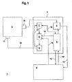
- Figure 1 shows schematically the structure of a device 1 for operating a Synchronous motor 2.
- the synchronous motor 2 is in the present case as rotative Drive formed with a rotor and stator.
- the device 1 comprises an amplifier unit 3 for controlling the synchronous motor 2 and an external control 4, by means of which the operation of the Synchronous motor 2 is controllable.
- the controller 4 may, for example, a PLC control or a CNC control.
- the amplifier unit 3 comprises a central unit 5, which acts as a microprocessor or the like may be formed. To this central unit 5 are a Evaluation circuit 6, a function module 7 and a relay assembly 8, the is performed on a power amplifier 9, connected.
- the evaluation circuit 6 measured values generated in a sensor 2a are measured evaluated.
- the evaluation circuit 6 preferably consists of an ASIC or FPGA.
- the encoder 2 a is arranged on the synchronous motor 2 and in the present Case as incremental encoder for determining the speed of the synchronous motor 2 trained.
- the encoder 2a as an absolute encoder, Resolver, half-sensor or the like may be formed.
- the functional module 7 is preferably designed as an ASIC or FPGA and forms a drive stage for the synchronous motor 2.
- the function module 7 as well as the evaluation circuit 6 of discrete electronic components and a microcontroller.
- the Current control of the synchronous motor performed.
- the relay assembly 8 consists of at least two series connected, independently switchable switching elements, preferably of relays special Design, in particular of safety relays with forced operation formed are.
- the controller 4 acts on at least one of the switching elements, the central unit 5 on at least one other switching element.
- the operation of a Switching element prevents the control of the power output stage 9 such that the emergence of a rotation of the field of rotation of the synchronous motor 2 generating is suppressed and / or the power supply of the power amplifier is prevented.
- the power output stage 9 is connected via a line 10 to a coil 11 of the synchronous motor 2 connected.
- the controller 4 is via bidirectional leads 12, 12 ⁇ to the controller. 4 connected.
- the registered in the evaluation circuit 6 actual positions of the synchronous motor 2 are read via a line 13 in the controller 4
- the controller 4 gives setpoints for the Operation of the synchronous motor 2, which implemented by the function module 7 become.
- the function module 7 controls the power output stage 9 in a suitable Way.
- the controller 4 transmits via the central unit 5 a setpoint torque with amount and direction to the function module 7th
- the controller 4 takes over the function of a first monitoring unit.
- the monitoring units are over the bidirectional Supply lines 12, 12 'between the central unit 5 and controller 4 coupled.
- the data is exchanged via the bidirectional Supply lines 12, 12 'a mutual monitoring of the monitoring units.
- having a predetermined level of security Device 1 is the speed by means of the first monitoring unit of the synchronous motor 2 as a function of the measured values of the encoder 2a regulated.
- a safe limit of the synchronous motor 2 are performed, is in the Control 4 as the first monitoring unit, the speed to the specified Limit regulated.
- the regulation takes place in dependence of the differentiated Measured values of the encoder 2a.
- the function module 7 as the second monitoring unit the Commutation of the synchronous motor 2 according to the stored limit value limited.
- the change of the commutation angle per unit time which is a measure of the speed of the rotor of the synchronous motor 2 forms, by means of the function module 7 to a corresponding Value limited.
- the relay assembly 8 to exceed the Limit value of the speed of the synchronous motor 2 to prevent.
- the power supply to the power output stage 9 is suppressed and / or the control the power output stage 9 is interrupted, so that the emergence a rotation field generating the movement of the synchronous motor 2 prevented becomes.
- the power output stage 9 driven by the function module 7, so that the synchronous motor 2 expires accordingly.
- the monitoring units thus control the power output stage 9 and the relay arrangement 8 as independent switch units for limiting the motor speed in the form that the emergence of a movement of the Synchronous motor 2 generating rotating field is suppressed.
- the form Monitoring units independent diversified units to limit the Engine speed.
- the function module 7 checks in this case the amount of the commutation angle and sets it to a motor speed limit Value.
- the synchronous motor 2 of the device 1 similar to a stepper motor operated.
- the controller transmits 4 a target speed with magnitude and sign to the function module 7, which then the synchronous motor 2 via the power output stage 9 accordingly controls.
- a constant current for the Synchronous motor 2 predetermined.
- the speed of the synchronous motor 2 is in turn via the controller 4 regulated as a function of the measured values of the encoder 2a.
- the limit for safe compliance with a limit speed is again in both monitoring units, that is in the controller 4 and in the Function module 7, deposited.
- the function module 7 If it is detected in the function module 7 that the limit value is exceeded, this disables independent of the signals of the controller 4, the power amplifier 9 and deactivated in particular by the control in the 4th performed speed control.
- the function module 7 in case of interruption of the speed control of the controller 4 send out an error message. As soon as the controller 4 registers the error has, this turns off the relay assembly 8, so that not only the function module 7, but also the controller 4 the synchronous motor 2 in the safe Condition convicted.
Landscapes
- Engineering & Computer Science (AREA)
- Power Engineering (AREA)
- Control Of Motors That Do Not Use Commutators (AREA)
- Control Of Ac Motors In General (AREA)
Applications Claiming Priority (2)
| Application Number | Priority Date | Filing Date | Title |
|---|---|---|---|
| DE102004019284A DE102004019284A1 (de) | 2004-04-21 | 2004-04-21 | Vorrichtung zum Betrieb eines Synchronmotors |
| DE102004019284 | 2004-04-21 |
Publications (2)
| Publication Number | Publication Date |
|---|---|
| EP1589653A2 true EP1589653A2 (fr) | 2005-10-26 |
| EP1589653A3 EP1589653A3 (fr) | 2009-03-25 |
Family
ID=34935069
Family Applications (1)
| Application Number | Title | Priority Date | Filing Date |
|---|---|---|---|
| EP05008015A Withdrawn EP1589653A3 (fr) | 2004-04-21 | 2005-04-13 | Dispositif pour entraîner un moteur synchrone |
Country Status (2)
| Country | Link |
|---|---|
| EP (1) | EP1589653A3 (fr) |
| DE (1) | DE102004019284A1 (fr) |
Cited By (1)
| Publication number | Priority date | Publication date | Assignee | Title |
|---|---|---|---|---|
| EP2398143A3 (fr) * | 2010-06-18 | 2017-08-02 | KUKA Roboter GmbH | Procédé et dispositif de surveillance d'une machine commandée par déplacement dotée d'un moteur d'entraînement commuté électroniquement |
Families Citing this family (11)
| Publication number | Priority date | Publication date | Assignee | Title |
|---|---|---|---|---|
| DE102006059708B4 (de) | 2006-12-18 | 2019-06-06 | Siemens Aktiengesellschaft | Antriebssteuerung für zumindest einen elektrischen Motor |
| DE102008031620A1 (de) * | 2008-07-07 | 2010-01-14 | Continental Automotive Gmbh | Verfahren und Vorrichtung zur Ansteuerung von bürstenlosen (EC)-Elektromotoren |
| KR101227336B1 (ko) | 2009-05-08 | 2013-01-28 | 미쓰비시덴키 가부시키가이샤 | 모터 제어 장치 |
| DE102010035972A1 (de) | 2010-08-31 | 2012-03-01 | Volkswagen Ag | Permanenterregte Synchronmaschine, Antriebseinheit und Verfahren zur Steuerung |
| DE102011075238B4 (de) * | 2011-05-04 | 2025-12-11 | Robert Bosch Gmbh | Verfahren und Vorrichtung zum Überwachen einer Winkellage eines Rotors in einer Elektromaschine |
| DE102012213709A1 (de) * | 2012-08-02 | 2014-02-06 | Continental Automotive Gmbh | Verfahren zum Erkennen eines Fehlerfalls einer Motoranordnung mit einer elektrischen Maschine und Motorsteuergerät |
| DE102012219914A1 (de) * | 2012-10-31 | 2014-04-30 | Continental Teves Ag & Co. Ohg | Überwachung eines elektronisch kommutierten Motors |
| DE102013220979A1 (de) * | 2013-04-26 | 2014-11-13 | Continental Automotive Gmbh | Verfahren und Vorrichtung zum Betrieb eines bürstenlosen Gleichstrommotors |
| JP6460927B2 (ja) | 2015-06-29 | 2019-01-30 | 日立オートモティブシステムズ株式会社 | 電動パワーステアリング装置の制御装置及び電動パワーステアリング装置 |
| DE102019213752A1 (de) * | 2019-09-10 | 2021-03-11 | Vitesco Technologies Germany Gmbh | Verfahren zur Steuerung einer Motoreinheit und Motoreinheit zur Durchführung eines solchen Verfahrens |
| DE102023110006A1 (de) * | 2023-04-20 | 2024-10-24 | Schaeffler Technologies AG & Co. KG | Rotorlageerfassungssystem und Radantriebssystem |
Family Cites Families (6)
| Publication number | Priority date | Publication date | Assignee | Title |
|---|---|---|---|---|
| DE4330823C2 (de) * | 1993-09-13 | 1997-12-11 | Bosch Gmbh Robert | Antriebsvorrichtung mit einer Sicherheitseinrichtung für den Sonderbetrieb |
| DE19908230A1 (de) * | 1999-02-25 | 2000-08-31 | Heidelberger Druckmasch Ag | Vorrichtung zur Überwachung von sicherheitsrelevanten Vorgängen an Maschinen |
| DE10041606B4 (de) * | 2000-08-24 | 2008-07-24 | Berger Lahr Gmbh & Co. Kg | Elektromotorischer Antrieb und Verfahren zum Betreiben eines elektronisch kommutierten Elektromotors |
| DE10059172A1 (de) * | 2000-11-29 | 2002-06-13 | Siemens Ag | Sichere Geschwindigkeitsüberwachung für geberlose Drehstromantriebe |
| DE10163010B4 (de) * | 2001-04-25 | 2007-01-25 | Siemens Ag | Verfahren und Einrichtung zur sicheren Überwachung der Drehzahl einer elektrischen Maschine |
| DE10207549B4 (de) * | 2002-02-22 | 2004-05-06 | Aradex Ag | Verfahren und Vorrichtung zum Betrieb eines Synchronmotors |
-
2004
- 2004-04-21 DE DE102004019284A patent/DE102004019284A1/de not_active Withdrawn
-
2005
- 2005-04-13 EP EP05008015A patent/EP1589653A3/fr not_active Withdrawn
Cited By (1)
| Publication number | Priority date | Publication date | Assignee | Title |
|---|---|---|---|---|
| EP2398143A3 (fr) * | 2010-06-18 | 2017-08-02 | KUKA Roboter GmbH | Procédé et dispositif de surveillance d'une machine commandée par déplacement dotée d'un moteur d'entraînement commuté électroniquement |
Also Published As
| Publication number | Publication date |
|---|---|
| EP1589653A3 (fr) | 2009-03-25 |
| DE102004019284A1 (de) | 2005-11-10 |
Similar Documents
| Publication | Publication Date | Title |
|---|---|---|
| EP2460056B1 (fr) | Procédé et dispositif de surveillance de l'absence d'erreur d'une grandeur de déplacement sur un mécanisme d'entraînement électrique | |
| EP2093642B1 (fr) | Table rotative avec une unité de contrôle ou regulation associée | |
| EP1589653A2 (fr) | Dispositif pour entraíner un moteur synchrone | |
| EP3378152B1 (fr) | Entraînement électrique pour un robot industriel | |
| DE102006046286A1 (de) | Bewegungsüberwachung | |
| EP1253490A2 (fr) | Procédé et dispositif de surveillance sécurisée de la vitesse | |
| DE102014106166B4 (de) | Vorrichtung und Verfahren zum fehlersicheren Überwachen eines beweglichen Maschinenteils | |
| EP1699676B1 (fr) | Procede de ralentissement d'un moteur electrique et mecanisme d'entrainement electrique | |
| EP3578295A1 (fr) | Dispositif de mesure de position et procédé de fonctionnement d'un dispositif de mesure de position | |
| EP3963611A1 (fr) | Ensemble commutateur comprenant un système d'entraînement | |
| EP1339164B1 (fr) | Méthode et dispositif d'entraîner un moteur synchrone | |
| EP3086464B1 (fr) | Procede destine au fonctionnement d'une machine electrique et entrainement | |
| DE3424247A1 (de) | Kollektorloser gleichstrommotor | |
| DE102010040801B4 (de) | Trennwand mit mehreren verfahrbaren Wandelementen und ein Verfahren zur Steuerung dieser Trennwand | |
| EP1597637A1 (fr) | Procede et dispositif pour deconnecter de maniere sure des commandes electriques | |
| WO2017102189A1 (fr) | Dispositif de contrôle protégé contre les erreurs de la vitesse d'un entraînement | |
| EP2568596A1 (fr) | Procédé et unité de traitement destinés à la détermination de la position du rotor d'une machine synchrone en fonction du stator de la machine synchrone | |
| EP1960852B1 (fr) | Dispositif de contrôle pour un dispositif d'entraînement | |
| DE10321465B4 (de) | Verfahren und Vorrichtung zum sicheren Abschalten von Antrieben bei Werkzeug- oder Produktionsmaschinen | |
| EP0770877A1 (fr) | Procédé de contrÔle de l'arrêt ou de la vitesse de rotation pendant le réglage d'un organe de commande, en particulier d'une servocommande à réponse rapide, et relais de puissance utilisé pour un tel procédé | |
| DE4322146A1 (de) | Verwendung eines elektrischen Antriebes für Bearbeitungsspindeln und Vorschubachsen an Werkzeugmaschinen | |
| DE102024131684A1 (de) | Verfahren zum Betreiben eines elektrischen Motors, elektrische Steuer- oder Auswertevorrichtung hierfür, sowie damit ausgestattete Maschine | |
| DE102013201241A1 (de) | Verfahren und Einrichtung zur Bestimmung der Position des Rotors bei einem bürstenlosen Gleichstrommotor | |
| EP3963612B1 (fr) | Ensemble commutateur comprenant un système d'entraînement et procédé pour faire fonctionner un commutateur | |
| WO2018115134A2 (fr) | Détermination sûre des positions axiales et/ou des vitesses axiales d'un robot |
Legal Events
| Date | Code | Title | Description |
|---|---|---|---|
| PUAI | Public reference made under article 153(3) epc to a published international application that has entered the european phase |
Free format text: ORIGINAL CODE: 0009012 |
|
| AK | Designated contracting states |
Kind code of ref document: A2 Designated state(s): AT BE BG CH CY CZ DE DK EE ES FI FR GB GR HU IE IS IT LI LT LU MC NL PL PT RO SE SI SK TR |
|
| AX | Request for extension of the european patent |
Extension state: AL BA HR LV MK YU |
|
| PUAL | Search report despatched |
Free format text: ORIGINAL CODE: 0009013 |
|
| AK | Designated contracting states |
Kind code of ref document: A3 Designated state(s): AT BE BG CH CY CZ DE DK EE ES FI FR GB GR HU IE IS IT LI LT LU MC NL PL PT RO SE SI SK TR |
|
| AX | Request for extension of the european patent |
Extension state: AL BA HR LV MK YU |
|
| 17P | Request for examination filed |
Effective date: 20090313 |
|
| 17Q | First examination report despatched |
Effective date: 20090507 |
|
| STAA | Information on the status of an ep patent application or granted ep patent |
Free format text: STATUS: THE APPLICATION HAS BEEN WITHDRAWN |
|
| 18W | Application withdrawn |
Effective date: 20090714 |