JP6207223B2 - Motor drive device and control method thereof - Google Patents
Motor drive device and control method thereof Download PDFInfo
- Publication number
- JP6207223B2 JP6207223B2 JP2013096522A JP2013096522A JP6207223B2 JP 6207223 B2 JP6207223 B2 JP 6207223B2 JP 2013096522 A JP2013096522 A JP 2013096522A JP 2013096522 A JP2013096522 A JP 2013096522A JP 6207223 B2 JP6207223 B2 JP 6207223B2
- Authority
- JP
- Japan
- Prior art keywords
- rotor
- signal
- motor
- phase
- drive
- Prior art date
- Legal status (The legal status is an assumption and is not a legal conclusion. Google has not performed a legal analysis and makes no representation as to the accuracy of the status listed.)
- Active
Links
Images


Classifications
-
- H—ELECTRICITY
- H02—GENERATION; CONVERSION OR DISTRIBUTION OF ELECTRIC POWER
- H02P—CONTROL OR REGULATION OF ELECTRIC MOTORS, ELECTRIC GENERATORS OR DYNAMO-ELECTRIC CONVERTERS; CONTROLLING TRANSFORMERS, REACTORS OR CHOKE COILS
- H02P8/00—Arrangements for controlling dynamo-electric motors of the kind having motors rotating step by step
- H02P8/36—Protection against faults, e.g. against overheating, step-out; Indicating faults
- H02P8/38—Protection against faults, e.g. against overheating, step-out; Indicating faults the fault being step-out
-
- H—ELECTRICITY
- H02—GENERATION; CONVERSION OR DISTRIBUTION OF ELECTRIC POWER
- H02P—CONTROL OR REGULATION OF ELECTRIC MOTORS, ELECTRIC GENERATORS OR DYNAMO-ELECTRIC CONVERTERS; CONTROLLING TRANSFORMERS, REACTORS OR CHOKE COILS
- H02P8/00—Arrangements for controlling dynamo-electric motors of the kind having motors rotating step by step
- H02P8/36—Protection against faults, e.g. against overheating, step-out; Indicating faults
Description
本発明は、ステッピングモータの駆動装置およびその制御方法に関し、特に駆動装置の消費電力を低減させる技術に関する。 The present invention relates to a stepping motor drive device and a control method thereof, and more particularly to a technique for reducing power consumption of the drive device.
ステッピングモータは小型、高トルク、高寿命という特徴を有し、開ループ制御により容易にデジタル的な位置決め動作を実現することができるため、カメラや光ディスク装置等の情報家電、或いは、プリンタやプロジェクタ等のOA機器等に広く用いられている。 Stepping motors have the characteristics of small size, high torque, and long life, and can easily realize digital positioning operation by open loop control. Therefore, information home appliances such as cameras and optical disk devices, printers, projectors, etc. It is widely used for OA equipment.
ステッピングモータの回転速度変化またはモータ電流変化によりステッピングモータの脱調を検出し、ステッピングモータが脱調しない範囲でステッピングモータの駆動電圧を低く設定することが知られている(特許文献1参照) It is known that a stepping motor step-out is detected based on a change in rotational speed or motor current of the stepping motor, and the stepping motor drive voltage is set low within a range in which the stepping motor does not step out (see Patent Document 1).
しかしながら、高精度なロータリーエンコーダは高価であるため、ステッピングモータの大幅なコストアップを招く。 However, since a high-precision rotary encoder is expensive, it greatly increases the cost of the stepping motor.
また、モータ電流変化にて脱調を高精度に検出する場合には、例えばステッピングモータの個体等を考慮して脱調判定基準を設定しなければならず、大幅なコストアップを招くという課題があった。 In addition, when step-out is detected with high accuracy based on a change in motor current, for example, the step-out determination criteria must be set in consideration of individual stepping motors, which causes a significant increase in cost. there were.
本発明は、大幅なコストアップを招くことなく、ステッピングモータを駆動する際の消費電力を低減させることを目的とする。 An object of the present invention is to reduce power consumption when driving a stepping motor without causing a significant cost increase.
本発明に係るモータ駆動装置は、コイルに通電することでロータを回転させるモータを駆動するモータ駆動装置であって、周期的に変化する駆動信号を前記コイルに供給する駆動手段と、前記ロータの回転に対応して出力信号が変化する信号出力手段と、前記駆動手段を制御する制御手段と、を有し、前記制御手段は、前記駆動信号に対して前記ロータの追従遅れがない場合に前記出力信号が所定の変化をするタイミングにおける前記駆動信号の第1の位相状態を記憶するとともに、前記出力信号が前記所定の変化をするタイミングにおける前記駆動信号の第2の位相状態と前記第1の位相状態の差分を求め、前記差分に基づいて、前記駆動手段が前記コイルに供給する前記駆動信号の振幅を制御することを特徴とする。 Motor driving apparatus according to the present invention, there is provided a motor driving apparatus for driving the motors for rotating the rotor by energizing the coil, a driving means for supplying a driving signal to the coil to change periodically, the A signal output means for changing an output signal corresponding to the rotation of the rotor, and a control means for controlling the drive means, wherein the control means has no follow-up delay of the rotor with respect to the drive signal; said output signal to store a first phase state of the drive signal at a timing that a predetermined change in conjunction with, the second phase states of the drive signal at a timing of pre-Symbol output signal to the predetermined change It calculates the difference between the first phase state, based on the previous SL difference, the drive means and controls the amplitude of the drive signal supplied to the coil.
本発明によれば、大幅なコストアップを招くことなく、ロータマグネットの回転位置を高精度に検出することができる。 According to the present invention, the rotational position of the rotor magnet can be detected with high accuracy without incurring a significant cost increase.
以下、本発明の実施形態について添付図面を参照して詳細に説明する。図1は、本発明の実施形態に係るモータ駆動ユニット100の外観構成を示す斜視図である。モータ駆動ユニット100は、ステッピングモータ101、ロータ軸102、ch0フォトインタラプタ103、ch1フォトインタラプタ104およびスリット回転板105を備える。
Hereinafter, embodiments of the present invention will be described in detail with reference to the accompanying drawings. FIG. 1 is a perspective view showing an external configuration of a
モータ駆動ユニット100において、スリット回転板105は、ロータ軸102に取り付けられており、明領域と暗領域との角度比率が50:50となるように設計されている。ステッピングモータ101を駆動すると、スリット回転板105が回転し、ch0フォトインタラプタ103とch1フォトインタラプタ104の出力信号は、後述の通りに変化する。
In the
図2は、モータ駆動ユニット100の構成を説明するブロック図である。図2に示す符号101〜105は、図1に示す符号101〜105に対応する。ステッピングモータ101は、A相用コイル113、B相用コイル114、A相+側ステータ115、A相−側ステータ116、B相+側ステータ117、B相−側ステータ118およびロータマグネット119(以下「ロータ119」という)を備える。A相用コイル113またはB相用コイル114に通電することで、ロータ119は回転する。なお、以下の説明において、A相+側ステータ115、A相−側ステータ116、B相+側ステータ117およびB相−側ステータ118を総じて、適宜、ステータと称する。
FIG. 2 is a block diagram illustrating the configuration of the
コンパレータ106は、ch0フォトインタラプタ103とch1フォトインタラプタ104から出力されるアナログ信号を受信し、予め設定された閾値電圧によって2値化された信号を後段のエンコーダ回路107へ出力する。本実施形態では、ステッピングモータ101を回転ムラなく一定の回転速度で回転させたときに、コンパレータ106の出力におけるHighとLowの比率が50:50となるように、閾値電圧が予め設定されている。以下、ch0フォトインタラプタ103の信号を2値化した信号をENC0信号と称呼し、ch1フォトインタラプタ104の信号を2値化した信号をENC1信号と称呼する。本実施形態では、ch0フォトインタラプタ103、ch1フォトインタラプタ104、スリット回転板105、コンパレータ106およびエンコーダ回路107が信号出力手段に対応する。また、ch0フォトインタラプタ103およびch1フォトインタラプタ104の分解能は、前述の通りに、コンパレータ106による2値化が可能な範囲で、正弦波発生器109の分解能よりも低いものを用いる。
The comparator 106 receives analog signals output from the
エンコーダ回路107は、ENC0信号とENC1信号の出力タイミングの取得と、信号による位置カウントと、信号周期カウントとを行う。エンコーダ回路107は、ENC0信号のLowからHighへの変化およびHighからLowの変化と、ENC1信号のLowからHighの変化およびHighからLowの変化との4種の信号出力タイミングを取得可能である。CPU108は、エンコーダ回路107の4種の信号出力タイミングに合わせて割り込み処理をかけることができる。その際に、CPU108は割り込み要因の4つの信号種別を判別する。
The
CPU108は、予め保存されているプログラムを実行する機能を備え、また、CPU108は、バス110を介してエンコーダ回路107、PWM発生器111に対してアクセスすることができる。
The
正弦波発生器109は、正弦波を発生させるものであって、発生させる正弦波1周期を512分割したテーブルを備えている。正弦波発生器109は、0から511までのテーブル番号に対応するPWM値をPWM発生器111に送る、PWM発生器111は、PWM信号をモータドライバ112に出力する。モータドライバ112は入力されたPWM信号を増幅させてステッピングモータ101のコイル(A相用コイル113およびB相用コイル114)に供給する。
The
正弦波発生器109からステッピングモータ101への駆動信号の供給に関して、図4および図5を参照して詳細に説明する。図4は、モータドライバ112の動作を説明する図である。図4(a)には、スイッチ401〜404を介して、A相用コイル113が接続されている状態が示されている。PWM発生器111から出力されるA相用のPWM信号がHigh信号である場合、スイッチ401とスイッチ404が閉じられ、図4(b)の状態となる。この状態では、A相用コイル113の両端にはA側を高電位としてモータドライバ112に供給されている電圧Vcc分の電位差が生じる。このとき、A相用コイル113のB側に対するA側の電位は、図4(f)に図示するように、+Vccとなる。また、このとき、A相用コイル113を流れる電流は、図4(i)に図示するように、+Iになる。
The supply of the drive signal from the
一方、PWM発生器111から出力されるA相用のPWM信号がLow信号である場合、スイッチ402とスイッチ403が閉じられ、図4(c)の状態となる。このとき、A相用コイル113の両端にはB側を高電位としてモータドライバ112に供給されている電圧Vcc分の電位差が生じる。このとき、A相用コイル113のB側に対するA側の電位は、図4(g)に図示するように、−Vccになる。また、このとき、A相用コイル113に流れる電流は、図4(j)に図示するように、−Iになる。
On the other hand, when the A-phase PWM signal output from the
図4(d),(e)は、図4(b),(c)の状態を短時間で繰り返した場合を示している。図4(h)は、図4(d),(e)の状態におけるA相用コイル113のB側に対するA側の電位を示す図である。図4(k)は、図4(d),(e)の状態におけるA相用コイル113を流れる電流を示す図である。図4(d),(e)の状態を等しい時間間隔で繰り返すと、図4(h)に示されるように、−Vccと+Vccの2値の矩形波状の電圧信号が発生する。この矩形波状の電圧信号がA相用コイル113に印加されると、コイルの電流遅れ成分により、電圧信号が平滑化された形で電流波形が現れ、−Vccと+Vccとがそれぞれ50%の場合には、電流が実効的に0(ゼロ)となる。従って、PWM信号のHigh信号率(以下、DUTY比率という)が50%のときに出力が0Vの定常電圧、100%のときに+Vccの定常電圧、75%のときに+Vcc/2の定常電圧が掛かっているのと等価として扱うことができる。
4D and 4E show a case where the states of FIGS. 4B and 4C are repeated in a short time. FIG. 4 (h) is a diagram showing the potential on the A side with respect to the B side of the
そこで、正弦波発生器109には、512個のテーブル番号のそれぞれにPWM信号のDUTY比率(%)の値が格納されている。図5は、正弦波発生器109に格納される0から511までのテーブル番号を説明する図である。図5に図示するように、正弦波の0°(度)位相にテーブル番号0、正弦波の180°位相にテーブル番号256が対応する。テーブル番号0および256には、DUTY比率50%の値が格納され、その後のテーブル番号には正弦波の位相に応じてPWM信号のDUTY比率の値が格納されている。図5に図示するように、本実施形態では、N極励磁のピークとなるテーブル番号128にDUTY比率100%より小さな値を格納し、S極励磁のピークとなるテーブル番号384にDUTY比率0%より大きな値を格納している。もし、N極励磁のピークとなるテーブル番号128にDUTY比率100%の値を格納すると、正弦波発生器109がテーブル番号128を出力するときには、PWM発生器111に+Vccの値を出力することになり、正弦波のゲインを変更することができない。このような点を考慮して、本実施形態では、N極励磁のピークとなるテーブル番号128はDUTY比率100%より小さな値に設定している。
Therefore, the
図4および図5にて説明したように、ステッピングモータ101のコイル(A相用コイル113およびB相用コイル114)に正弦波状の電圧信号を印加することができる。すなわち、本実施形態では、ステッピングモータ101をマイクロステップ駆動している。以下の説明では、A相用コイル113およびB相用コイル114に印加される電圧信号は正弦波であるとする。
As described with reference to FIGS. 4 and 5, sinusoidal voltage signals can be applied to the coils (the
本実施形態では、正弦波発生器109、PWM発生器111およびモータドライバ112が駆動手段に対応し、A相用コイル113およびB相用コイル114に印加される正弦波状の電圧信号が周期的に変化する駆動信号に対応する。また、本実施形態では、正弦波発生器109が正弦波1周期を512分割しているので、ステッピングモータ101が1回転する間にA相用コイル113およびB相用コイル114に印加される正弦波状の電圧信号の状態が512回変化する。すなわち、ステッピングモータ101が1回転する間にコンパレータ106がENC0信号およびENC1信号を出力する回数は、ステッピングモータ101が1回転する間にA相用コイル113およびB相用コイル114に印加される正弦波状の電圧信号の状態が変化する回数よりも少ない。
In this embodiment, the
図2の説明に戻る。A相用コイル113は、正弦波状の電圧信号を受けて、A相+側ステータ115およびA相−側ステータ116に磁極をそれぞれ励磁する。同様に、B相用コイル114は、正弦波状の電圧信号を受けて、B相+側ステータ117およびB相−側ステータ118に磁極をそれぞれ励磁する。A相用コイル113に印加される電圧信号とB相用コイル114に印加される電圧は互いに位相が異なっている。図3および図6を参照して、A相用コイル113に印加される正弦波状の電圧信号、B相用コイル114に印加される正弦波状の電圧信号、ステータに励磁される磁極、ロータ119の停止位置およびスリット回転板105の位置の関係について説明する。
Returning to the description of FIG. The
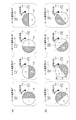
図3(a)は、ステッピングモータ101の構成を説明する図である。ロータ119は、自由に回転可能であり、ロータ119の周囲には物理角で18°毎にステータ(A相+側ステータ115、A相−側ステータ116、B相+側ステータ117およびB相−側ステータ118)が、図3(a)に示す通りに配置されている。
FIG. 3A is a diagram illustrating the configuration of the stepping
A相用コイル113に印加される電圧信号が正弦波形の正の領域にあるときには、A相+側ステータ115にN極が励磁され、A相−側ステータ116にS極が励磁される。A相用コイル113に印加される電圧信号が正弦波形の負の領域にあるときには、A相+側ステータ115にS極が励磁され、A相−側ステータ116にN極が励磁される。
When the voltage signal applied to the
B相用コイル114に印加される電圧信号が正弦波形の正の領域にあるときには、B相+側ステータ117にN極が励磁され、B相−側ステータ118にS極が励磁される。B相用コイル114に印加される電圧信号が正弦波形の負の領域にあるときには、B相+側ステータ117にS極が励磁され、B相−側ステータ118にN極が励磁される。
When the voltage signal applied to the
図6(a)は、ロータ119を正転方向に回転させるためにA相用コイル113およびB相用コイル114に印加する正弦波状の電圧信号を示す図である。また、図6(b)は、ロータ119を正転方向とは逆の逆転方向に回転させるためにA相用コイル113およびB相用コイル114に印加する正弦波状の電圧信号を示す図である。なお、図6では、正弦波形の正領域にN極、負領域にS極と書かれているが、これはA相+側ステータ115およびB相+側ステータ117に励磁される磁極を示している。このとき、A相−側ステータ116に励磁される磁極はA相+側ステータ115の反対の磁極になり、B相−側ステータ118に励磁される磁極はB相+側ステータ117の反対の磁極になる。
FIG. 6A is a diagram showing sinusoidal voltage signals applied to the
ロータ119を正転方向に回転させる際に、正弦波発生器109は、テーブル番号を正方向に進めて駆動信号を生成する。ロータ119を逆転方向に回転させる際に、正弦波発生器109は、テーブル番号を逆方向に進めて駆動信号を生成する。また、A相用コイル113およびB相用コイル114への出力は、ロータ119を正転方向に回転させる際には、A相用コイル113への出力がsin波、B相用コイル114への出力がcos波となる。このとき、B相用コイル114への出力はA相用コイル113への出力に対して90°進む。ロータ119を逆転方向に回転させる際には、B相用コイル114への出力はA相用コイル113への出力に対して90°遅れる。図3(b),(c)は、ロータ119、ch0フォトインタラプタ103、ch1フォトインタラプタ104、スリット回転板105、A相+側ステータ115およびB相+側ステータ117の物理的な位置関係を示す図である。なお、本実施形態では、ステッピングモータ101は、図3(a)に示すように20個のステータを備えるが、図3(b),(c)では、A相+側ステータ115およびB相+側ステータ117の位置で代表させている。
When rotating the
図3(b)は、ロータ119の着磁位相とスリット回転板105とが基準位置関係にある状態を示している。ここで、基準位置関係とは、ロータ119のN極領域とスリット回転板105の明領域とが一致する位置関係である。すなわち、スリット回転板105が基準位置関係でロータ119に取り付けられていれば、ロータ119のN極領域とスリット回転板105の明領域とが一致する。
FIG. 3B shows a state where the magnetization phase of the
図3(c)は、図3(b)に示す基準位置関係からスリット回転板105が逆転方向に電気角で180°だけずれた位置でロータ119に取り付けられた状態を示している。ここで、電気角とは、コイルに印加する駆動信号が1周期分変化したときに、ロータが360°回転すると定義したものである。よって、本実施形態の場合、スリット回転板105とロータ119の物理角度72°が電気角360°に相当する。
FIG. 3C shows a state in which the
図3(a)に示すように、A相+側ステータ115から逆転方向に物理角18°だけ離れた位置にB相+側ステータ117が配置される。本実施形態では、ch0フォトインタラプタ103がB相+側ステータ117と同じ位置に配置され、ch1フォトインタラプタ104がA相+側ステータ115と同じ位置に設置されている。これよって、ロータ119と共に回転するスリット回転板105の回転に対応して、ch0フォトインタラプタ103とch1フォトインタラプタ104はそれぞれ、ロータ119の着磁位相に対応した信号を出力する。すなわち、ロータ119の回転に対応して、ch0フォトインタラプタ103またはch1フォトインタラプタ104から出力される信号が変化する。
As shown in FIG. 3A, the B-phase +
図7は、図3に示すようにN極とS極とを5極ずつ備えるロータ119を、N極とS極とを1極ずつ備える構成にモデル化した図である。このようなモデル化を行うことにより、電気角と物理角とを一致させることができる。以後の説明は、このモデルを用いて行う。
FIG. 7 is a diagram obtained by modeling the
図7(a)の左側図は、ロータ119の着磁位相とスリット回転板105の明暗位相とが基準位置関係にある状態を示している。また、図7(a)の右側図(グラフ)は、図7(a)の左側図の状態からロータ119を正転方向にθ°回転させた場合のENC0信号とENC1信号の出力変化を示している。なお、図7にあるENC0信号はch0フォトインタラプタ103の出力を2値化した信号であり、ENC1信号はch1フォトインタラプタ104の出力を2値化した信号である。
The left view of FIG. 7A shows a state where the magnetization phase of the
図7(b)の左側図は、図7(a)の左側図の状態に対してスリット回転板105が電気角でα°だけ逆転方向にずれた状態を示している。図7(b)の右側図(グラフ)は、図7(b)の左側図の状態からロータ119を正転方向にθ°回転させた場合のENC0信号とENC1信号の出力変化を示している。図7(b)の状態では、図7(a)の状態と比較して、ENC0信号とENC1信号が電気角でα°だけ遅れて出力される。ロータ119を逆転方向に回転させた場合、ENC0信号とENC1信号は、電気角α°だけ進んで出力される。なお、スリット回転板105の取り付け位置のずれ角度(α°)は、モータ駆動ユニット100の製造時に特定されている。
The left view of FIG. 7B shows a state in which the
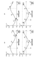
図8は、ロータ119を正転方向に回転させた際に、ロータ119の電気角とロータ119の回転位置との関係を説明する図である。図8(a)は、A相用コイル113およびB相用コイル114に印加する正弦波状の電圧信号に対してロータ119の追従遅れが生じていない場合を示している。図8(b)は、A相用コイル113およびB相用コイル114に印加する正弦波状の電圧信号に対してロータ119の追従遅れが生じている場合を示している。図8(a)および(b)には、ロータ119の電気角が0°,90°,180°,270°となる状態がそれぞれ示されている。図8(a)および(b)に図示されるロータ119の電気角が0°では、A相+側ステータ115にS極が励磁され、B相+側ステータ117にはN極もS極も励磁されていない。図8(a)および(b)に図示されるロータ119の電気角が90°では、A相+側ステータ115にはN極もS極も励磁されず、B相+側ステータ117にN極が励磁される。図8(a)および(b)に図示されるロータ119の電気角180°のときにはA相+側ステータ115にN極が励磁され、B相+側ステータ117にはN極もS極も励磁されていない。図8(a)および(b)に図示されるロータ119の電気角270°のときにはA相+側ステータ115にはN極もS極も励磁されず、B相+側ステータ117にS極が励磁される。図8(a)でも、図8(b)でも、それぞれの状態でA相+側ステータ115およびB相+側ステータ117に励磁される磁極は同じであるが、図8(b)では、ロータ119の追従遅れ801が生じている。
FIG. 8 is a diagram illustrating the relationship between the electrical angle of the
図9は、ロータ119を正転方向に回転させた際の、A相用コイル113およびB相用コイル114に印加する電圧信号と、ロータ119の回転位置と、ch0フォトインタラプタ103およびch1フォトインタラプタ104の出力との関係を示している。
FIG. 9 shows voltage signals applied to the
図9(a)は、A相用コイル113に印加される正弦波状の電圧信号を示し、図9(b)は、B相用コイル114に印加される正弦波状の電圧信号を示す図である。図9(a)にて、A相用コイル113に印加される正弦波状の電圧信号が正の領域となるとき、A相+側ステータ115にはN極が励磁され、A相用コイル113に印加される正弦波状の電圧信号が負の領域となるとき、A相+側ステータ115にはS極が励磁される。図9(b)にて、B相用コイル114に印加される正弦波状の電圧信号が正の領域となるとき、B相+側ステータ117にはN極が励磁され、B相用コイル114に印加される正弦波状の電圧信号が負の領域となるとき、B相+側ステータ117にはS極が励磁される。
FIG. 9A shows a sinusoidal voltage signal applied to the
図8(a)および(b)に示す電気角0°,90°,180°,270°の状態は、図9に示す電気角0°,90°,180°,270°の状態に対応している。すなわち、A相用コイル113に図9(a)に図示される正弦波状の電圧信号を印加し、B相用コイル114に、図9(b)に図示される正弦波状の電圧信号を印加すると、ロータ119は図8(a)または(b)のように回転する。
The states of
図9(d)は、A相用コイル113に印加される正弦波状の電圧信号に基づいて正弦波発生器109から出力されるテーブル番号の変化を示す図である。A相用コイル113に印加される正弦波状の電圧信号1周期で、正弦波発生器109から出力されるテーブル番号は0から512まで変化する。正弦波発生器109から出力されるテーブル番号を検出することで、A相用コイル113に印加される電圧信号の位相(状態)を検出することができる。また、A相用コイル113に印加される電圧信号とB相用コイル114に印加される電圧信号の位相差は90°であることが分かっているので、正弦波発生器109から出力されるテーブル番号を検出することで、B相用コイル114に印加される電圧信号の位相(状態)も検出することができる。
FIG. 9D is a diagram showing a change in the table number output from the
図9(c)は、正弦波発生器109から出力されるテーブル番号を積算した値である。この値は、ロータ119が1回転すると512増加する。本実施形態では、ロータ119の電気角が最初に0°になるとき、テーブル番号の積算値は1408となり、ロータ119が1回転してロータ119の電気角が再度0°になるとき、テーブル番号の積算値は1920となる。
FIG. 9C is a value obtained by integrating the table numbers output from the
図9(e)および(f)は、図8(a)に図示したようにA相用コイル113およびB相用コイル114に印加する電圧信号に対してロータ119の追従遅れが生じていない場合におけるロータ119の位置を示している。
FIGS. 9E and 9F show the case where the follow-up delay of the
図9(e)にて破線で描かれるように、A相+側ステータ115にロータ119のN極が接近しているときに正の領域となり、A相+側ステータ115にロータ119のS極が接近しているときに負の領域となる。
As depicted by a broken line in FIG. 9 (e), a positive region is obtained when the N pole of the
図9(e)にてロータ119の電気角が0°となる状態は、図8(a)にてロータ119の電気角が0°となる状態に対応している。図8(a)にてロータ119の電気角が0°となる状態では、A相+側ステータ115にロータ119のN極の中心が向かい合っている。したがって、図9(e)にて破線で描かれる正弦波は、ロータ119の電気角が0°となる状態にて、最大になる。
The state where the electrical angle of the
図9(f)にて破線で描かれるように、B相+側ステータ117にロータ119のN極が接近しているときに正の領域となり、B相+側ステータ117にロータ119のS極が接近しているときに負の領域となる。
As depicted by a broken line in FIG. 9 (f), a positive region is obtained when the north pole of the
図9(f)にてロータ119の電気角が270°となる状態は、図8(a)にてロータ119の電気角が270°となる状態に対応している。図8(a)にてロータ119の電気角が270°となる状態では、B相+側ステータ117にロータ119のN極の中心が向かい合っている。したがって、図9(f)にて破線で描かれる正弦波は、ロータ119の電気角が270°となる状態にて、最大になる。
The state in which the electrical angle of the
図9(g)は、図8(a)に図示したようにA相用コイル113およびB相用コイル114に印加する電圧信号に対してロータ119の追従遅れが生じていない場合におけるch0フォトインタラプタ103およびch1フォトインタラプタ104の出力を示している。すなわち、ロータ119のそれぞれの電気角におけるENC0信号(ch0フォトインタラプタ103の出力を2値化)とENC1信号(ch1フォトインタラプタ104の出力を2値化)を示している。図9(g)では、図7で説明したスリット回転板105の取り付け位置のずれ角度α°を反映しており、ENC0信号、ENC1信号がα°だけ遅れてHigh/Lowで変化する様子を示している。
FIG. 9G shows the ch0 photointerrupter when the follow-up delay of the
図9(h)および(i)は、図8(b)に図示したようにA相用コイル113およびB相用コイル114に印加する電圧信号に対してロータ119の追従遅れが生じている場合におけるロータ119の位置を示している。図8(b)に図示されるロータ119の追従遅れ801は、図9の追従遅れ量925に対応する。
9 (h) and 9 (i) show a case where the follow-up delay of the
図9(h)にて破線で描かれるように、A相+側ステータ115にロータ119のN極が接近しているときに正の領域となり、A相+側ステータ115にロータ119のS極が接近しているときに負の領域となる。図9(h)にて破線で描かれる正弦波は、図9(e)にて破線で描かれる正弦波に対して追従遅れ量925だけ遅れる。
As depicted by a broken line in FIG. 9H, a positive region is obtained when the N pole of the
図9(h)にてロータ119の電気角が0°から90°となる状態は、図8(b)にてロータ119の電気角が0°から90°となる状態に対応している。図8(b)にてロータ119の電気角が0°から90°までの間の状態で、A相+側ステータ115にロータ119のN極の中心が向かい合う。したがって、図9(e)にて破線で描かれる正弦波は、ロータ119の電気角が0°から90°までの間の状態で、最大になる。
The state where the electrical angle of the
図9(i)にて破線で描かれるように、B相+側ステータ117にロータ119のN極が接近しているときに正の領域となり、B相+側ステータ117にロータ119のS極が接近しているときに負の領域となる。図9(i)にて破線で描かれる正弦波は、図9(f)にて破線で描かれる正弦波に対して追従遅れ量925だけ遅れる。
As depicted by a broken line in FIG. 9 (i), a positive region is obtained when the north pole of the
図9(i)にてロータ119の電気角が270°から0°となる状態は、図8(b)にてロータ119の電気角が270°から0°となる状態に対応している。図8(b)にてロータ119の電気角が270°から0°までの間の状態で、B相+側ステータ117にロータ119のN極の中心が向かい合う。したがって、図9(i)にて破線で描かれる正弦波は、ロータ119の電気角が270°から0°までの間の状態で、最大になる。
The state in which the electrical angle of the
図9(j)は、図8(b)に図示したようにA相用コイル113およびB相用コイル114に印加する電圧信号に対してロータ119の追従遅れが生じている場合におけるch0フォトインタラプタ103およびch1フォトインタラプタ104の出力を示している。すなわち、ロータ119のそれぞれの電気角におけるENC0信号(ch0フォトインタラプタ103の出力を2値化したもの)とENC1信号(ch1フォトインタラプタ104の出力を2値化したもの)を示している。ENC0信号とENC1信号も、図9(g)の信号変化位置から追従遅れ量925の分だけ遅れてHigh/Lowが変化する。図9(g)の追従遅れ量925は図8(b)の追従遅れ801に対応している。
FIG. 9J shows the ch0 photointerrupter when the follow-up delay of the
図10は、ロータ119を逆転方向に回転させた際に、ロータ119の電気角とロータ119の回転位置との関係を説明する図である。図8では、ロータ119の回転方向が正転方向あったのに対して、図10では、ロータ119の回転方向が逆転方向である。図10(a)は、A相用コイル113およびB相用コイル114に印加する正弦波状の電圧信号に対してロータ119の追従遅れが生じていない状態を示している。図10(b)は、A相用コイル113およびB相用コイル114に印加する正弦波状の電圧信号に対してロータ119の追従遅れが生じている状態を示している。すなわち、図10(b)では、ロータ119の追従遅れ1001が生じている。図10についての詳細な説明は、図8と同様であるため省略する。図10(b)に図示されるロータ119の追従遅れ1001は、図11の追従遅れ量1125に対応する。
FIG. 10 is a diagram illustrating the relationship between the electrical angle of the
図11は、ロータ119を逆転方向に回転させた際の、A相用コイル113およびB相用コイル114に印加する電圧信号と、ロータ119の回転位置と、ch0フォトインタラプタ103およびch1フォトインタラプタ104の出力信号との関係を示している。
FIG. 11 shows voltage signals applied to the
図11(a)〜(j)についての詳細な説明は、図9(a)〜(j)と同様であるため省略する。 Detailed descriptions of FIGS. 11A to 11J are the same as those of FIGS. 9A to 9J, and will be omitted.
ロータ119を正転方向に回転させた場合とロータ119を逆転方向に回転させた場合での相違点を説明する。ロータ119を逆転方向に回転させた場合には、図11(d)に示すように正弦波発生器109から出力されるテーブル番号が小さくなっていく。したがって、正弦波発生器109から出力されるテーブル番号を積算した値も小さくなり、ロータ119が1回転すると512減少する。また、図11(g)および(j)に示すように、スリット回転板105の取り付け位置のずれ角度α°の影響が進み方向に出る。すなわち、ロータ119を逆転方向に回転させた場合には、ENC0信号およびENC1信号がα°だけ進んでHigh/Lowで変化する。
Differences between when the
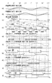
図12および図13は、ロータ119の位置検出処理を含む、ステッピングモータ101の駆動方法を示すフローチャートである。ステップS1200にて、CPU108は、モータドライバ112がA相用コイル113およびB相用コイル114に印加する駆動電圧V0を3.5vに設定する。ステップS1201にて、CPU108は、ch0フォトインタラプタ103およびch1フォトインタラプタ104の変化タイミングの基準位置設定を行う。ここでは、ロータ119の追従遅れがない場合にてENC0信号のHigh/Lowが変化するタイミングに対応するテーブル番号と、ENC1信号のHigh/Lowが変化するタイミングに対応するテーブル番号と、を基準位置として設定する。
12 and 13 are flowcharts showing a method for driving the stepping
ロータ119を正転方向に回転させる際の基準位置設定方法について、図9を参照して具体的に説明する。図9(g)に図示されるように、ENC1信号がHighからLowに変化するタイミングがE1(E5)である。ENC0信号がLowからHighに変化するタイミングがE2(E6)である。ENC1信号がLowからHighに変化するタイミングがE3である。ENC0信号がHighからLowに変化するタイミングがE4である。ENC1信号がHighからLowに変化するタイミングE1(E5)では、テーブル番号0にαだけ加算した位置905(913)を基準位置として設定する。ENC0信号がLowからHighに変化するタイミングE2(E6)では、テーブル番号128にαだけ加算した位置907(915)を基準位置として設定する。ENC1信号がLowからHighに変化するタイミングE3では、テーブル番号256にαだけ加算した位置909を基準位置として設定する。ENC0信号がHighからLowに変化するタイミングE4では、テーブル番号384にαだけ加算した位置911を基準位置として設定する。このときのαは、図7で説明したスリット回転板105の取り付け位置ズレα°を、正弦波1周期を512のテーブル番号に換算したものである。
A reference position setting method for rotating the
ロータ119を逆転方向に回転させる際の基準位置設定について、図11を参照して具体的に説明する。図11(g)に図示されるように、ENC1信号がLowからHighに変化するタイミングがE1(E5)である。ENC0信号がLowからHighに変化するタイミングがE2(E6)である。ENC1信号がHighからLowに変化するタイミングがE3である。ENC0信号がHighからLowに変化するタイミングがE4である。ENC1信号がLowからHighに変化するタイミングがE1(E5)では、テーブル番号0にαだけ加算した位置1105(1113)を基準位置として設定する。ENC0信号がLowからHighに変化するタイミングE2(E6)では、テーブル番号384にαだけ加算した位置1107を基準位置として設定する。また、ENC1信号がHighからLowに変化するタイミングE3では、テーブル番号256にαだけ加算した位置1109を基準位置として設定する。ENC0信号がHighからLowに変化するタイミングE4では、テーブル番号128にαだけ加算した位置1111を基準位置として設定する。
The reference position setting when rotating the
このように、ステップS1201では、ロータ119が正転方向に回転する場合と逆転方向に回転する場合にて、ENC0信号とENC1信号のHigh/Lowが変化するタイミングに対応するテーブル番号を適当な変数領域に格納する。なお、ステップS1201で設定される基準位置は、A相用コイル113およびB相用コイル114に印加される電圧信号に対して、ロータ119の追従遅れが生じない場合の基準位置である。
In this way, in step S1201, the table number corresponding to the timing at which the High / Low of the ENC0 signal and ENC1 signal change depending on whether the
ステップS1202において、CPU108は、ステップS1201で設定した8個の値の中に512を超えるものがないかを判定する。もし、設定した値の中に512を越える値があれば、その値から512を減算して、基準位置として設定する。ステップS1202の処理は、テーブル番号の最大値が511であるので、0〜511の間の値に正規化するための処理である。
In step S1202, the
CPU108は、ステップS1205において、ステッピングモータ101に対する駆動開始命令が発生しているかを判定する。CPU108は、駆動開始命令が発生している場合(S1205でYES)、処理をステップS1206へ進め、駆動開始命令が発生していない場合(S1205でNO)、ステップS1205の処理を繰り返す。
In step S1205, the
ステップS1206において、CPU108は、駆動開始命令と共に送られてきた回転方向、速度、目標停止位置の指令値を設定する。そして、ステップS1207において、CPU108は、ステップS1201で設定した基準位置と、実際にENC0信号およびENC1信号のHigh/Lowが変化するタイミングに対応するテーブル番号との差分を格納する変数DiffCntにゼロ(0)を設定する。そして、CPU108は、駆動信号の位相(状態)に対するテーブル番号を設定値に応じた条件でステッピングモータ101の駆動を開始する。
In step S1206, the
ステップS1208において、CPU108は、ENC0信号またはENC1信号のHigh/Low変化が発生したかどうかを判定する。ENC0信号またはENC1信号のHigh/Low変化が発生した場合(S1208でYES)、CPU108は、処理をステップS1209へ進める。ENC0信号またはENC1信号のHigh/Low変化が発生しない場合(S1208でNO)、CPU108は、処理をステップS1230へ進める。
In step S1208, the
ステップS1209では、CPU108が、駆動開始命令と共に送られてきた回転方向の情報に基づいて、ロータ119を正転方向に回転させるのか、逆転方向に回転させるのかを判定する。ロータ119を正転方向に回転させる場合(S1209でYES)には、処理をステップS1210へ進める。ロータ119を逆転方向に回転させる場合(S1209でNO)には、処理をステップS1211へ進める。
In step S1209, the
ステップS1210では、ステップS1208で発生したENC0信号またはENC1信号のHigh/Low変化がENC0信号のHigh/Low変化なのか否かをCPU108が判定する。ENC0信号のHigh/Low変化であると判定される場合(S1210でYES)、処理をステップS1212へ進める。ENC0信号のHigh/Low変化でないと判定される場合(S1210でNO)、処理をステップS1213へ進める。
In step S1210, the
ステップS1212では、ENC0信号がLowからHighに変化しているのか否かをCPU108が判定する。ENC0信号がLowからHighに変化していると判定される場合(ステップS1212でYES)には、処理をステップS1216へ進める。ENC0信号がLowからHighに変化していないと判定される場合(ステップS1212でNO)には、処理をステップS1217へ進める。
In step S <b> 1212, the
ステップS1216では、ENC0信号がLowからHighに変化したタイミングに対応するテーブル番号を取得し、ステップS1201にて基準位置として設定した位置907(915)との差分を変数DiffCntに格納する。変数DiffCntに格納される値は、A相用コイル113およびB相用コイル114に印加する正弦波状の電圧信号に対するロータ119の追従遅れ量をテーブル番号で表わしたものとなる。
In step S1216, a table number corresponding to the timing at which the ENC0 signal changes from low to high is acquired, and the difference from the position 907 (915) set as the reference position in step S1201 is stored in the variable DiffCnt. The value stored in the variable DiffCnt represents the follow-up delay amount of the
図9(d)および(j)を参照して、ステップS1216の処理を具体的に説明する。ステップS1216を実行するのは、ENC0信号がLowからHighに変化するタイミングE8(E12)である。ENC0信号がLowからHighに変化するタイミングE8(E12)に対応するテーブル番号は位置908(916)である。このとき、差分918(922)が変数DiffCntに格納される。差分918(922)がA相用コイル113およびB相用コイル114に印加する正弦波状の電圧信号に対するロータ119の追従遅れ量に対応する。
With reference to FIG.9 (d) and (j), the process of step S1216 is demonstrated concretely. Step S1216 is executed at timing E8 (E12) when the ENC0 signal changes from Low to High. The table number corresponding to the timing E8 (E12) at which the ENC0 signal changes from Low to High is the position 908 (916). At this time, the difference 918 (922) is stored in the variable DiffCnt. The difference 918 (922) corresponds to the follow-up delay amount of the
ステップS1212にて、ENC0信号がLowからHighに変化していないと判定される場合には、ENC0信号がHighからLowに変化したことになり、処理をステップS1217へ進める。 If it is determined in step S1212 that the ENC0 signal has not changed from Low to High, the ENC0 signal has changed from High to Low, and the process advances to step S1217.
ステップS1217では、ENC0信号がHighからLowに変化したタイミングに対応するテーブル番号を取得し、ステップS1201にて基準位置として設定した位置911との差分を変数DiffCntに格納する。変数DiffCntに格納される値は、A相用コイル113およびB相用コイル114に印加する正弦波状の電圧信号に対するロータ119の追従遅れ量をテーブル番号で表わしたものとなる。
In step S1217, a table number corresponding to the timing at which the ENC0 signal changes from high to low is acquired, and the difference from the
図9(d)および(j)を参照して、ステップS1217の処理を具体的に説明する。ステップS1217を実行するのは、ENC0信号がHighからLowに変化するタイミングE10である。ENC0信号がHighからLowに変化するタイミングE10に対応するテーブル番号は位置912である。このとき、差分920が変数DiffCntに格納される。
With reference to FIG.9 (d) and (j), the process of step S1217 is demonstrated concretely. Step S1217 is executed at timing E10 when the ENC0 signal changes from High to Low. The table number corresponding to the timing E10 at which the ENC0 signal changes from High to Low is the
ステップS1210にて、ENC0信号のHigh/Low変化でないと判定される場合には、ステップS1208でENC1信号のHigh/Low変化が発生したことになり、処理をステップS1213へ進める。 If it is determined in step S1210 that there is no high / low change in the ENC0 signal, it means that a high / low change in the ENC1 signal has occurred in step S1208, and the process advances to step S1213.
ステップS1213では、ENC1信号がLowからHighに変化しているのか否かをCPU108が判定する。ENC1信号がLowからHighに変化していると判定される場合(ステップS1213でYES)には、処理をステップS1218へ進める。ENC1信号がLowからHighに変化していないと判定される場合(ステップS1213でNO)には、処理をステップS1219へ進める。
In step S1213, the
ステップS1218では、ENC1信号がLowからHighに変化したタイミングに対応するテーブル番号を取得し、ステップS1201にて基準位置として設定した位置909との差分を変数DiffCntに格納する。変数DiffCntに格納される値は、A相用コイル113およびB相用コイル114に印加する正弦波状の電圧信号に対するロータ119の追従遅れ量をテーブル番号で表わしたものとなる。
In step S1218, a table number corresponding to the timing at which the ENC1 signal changes from low to high is acquired, and the difference from the
図9(d)および(j)を参照して、ステップS1218の処理を具体的に説明する。ステップS1218を実行するのは、ENC1信号がLowからHighに変化するタイミングE9である。ENC1信号がLowからHighに変化するタイミングE9に対応するテーブル番号は位置910である。このとき、差分919が変数DiffCntに格納される。
With reference to FIG.9 (d) and (j), the process of step S1218 is demonstrated concretely. Step S1218 is executed at timing E9 when the ENC1 signal changes from Low to High. The table number corresponding to the timing E9 at which the ENC1 signal changes from Low to High is the
ステップS1213にて、ENC1信号がLowからHighに変化していないと判定される場合には、ENC1信号がHighからLowに変化したことになり、処理をステップS1219へ進める。 If it is determined in step S1213 that the ENC1 signal has not changed from Low to High, the ENC1 signal has changed from High to Low, and the process proceeds to step S1219.
ステップS1219では、ENC1信号がHighからLowに変化したタイミングに対応するテーブル番号を取得し、ステップS1201にて基準位置として設定した位置905(913)との差分を変数DiffCntに格納する。変数DiffCntに格納される値は、A相用コイル113およびB相用コイル114に印加する正弦波状の電圧信号に対するロータ119の追従遅れ量をテーブル番号で表わしたものとなる。
In step S1219, the table number corresponding to the timing at which the ENC1 signal changes from High to Low is acquired, and the difference from the position 905 (913) set as the reference position in Step S1201 is stored in the variable DiffCnt. The value stored in the variable DiffCnt represents the follow-up delay amount of the
図9(d)および(j)を参照して、ステップS1219の処理を具体的に説明する。ステップS1219を実行するのは、ENC1信号がHighからLowに変化するタイミングE7(E11)である。ENC1信号がHighからLowに変化するタイミングE7(E11)に対応するテーブル番号は位置906(914)である。このとき、差分917(921)が変数DiffCntに格納される。 With reference to FIG.9 (d) and (j), the process of step S1219 is demonstrated concretely. Step S1219 is executed at timing E7 (E11) when the ENC1 signal changes from High to Low. The table number corresponding to the timing E7 (E11) at which the ENC1 signal changes from High to Low is the position 906 (914). At this time, the difference 917 (921) is stored in the variable DiffCnt.
ステップS1216〜S1219にて、変数DiffCntに格納される差分917〜922は、テーブル番号の値に換算されて変数DiffCntに格納される。ロータ119を正転方向に回転させる場合、変数DiffCntに格納される差分917〜922は、正の値となる。
In steps S1216 to S1219, the differences 917 to 922 stored in the variable DiffCnt are converted into the values of the table numbers and stored in the variable DiffCnt. When the
ステップS1209にて、ロータ119を逆転方向に回転させると判定される場合には、処理をステップS1211へ進める。ステップS1211の処理は、ステップS1210と同じである。ステップS1208で発生したENC0信号またはENC1信号のHigh/Low変化がENC0信号のHigh/Low変化であれば、処理をステップS1214へ進め、そうでなければ処理をステップS1215へ進める。
If it is determined in step S1209 that the
ステップS1214の処理は、ステップS1212と同じである。ENC0信号がLowからHighに変化していれば、処理をステップS1220へ進め、そうでなければ処理をステップS1221へ進める。 The process of step S1214 is the same as that of step S1212. If the ENC0 signal has changed from Low to High, the process proceeds to step S1220; otherwise, the process proceeds to step S1221.
ステップS1215の処理は、ステップS1213と同じである。ENC1信号がLowからHighに変化していれば、処理をステップS1222へ進め、そうでなければ処理をステップS1223へ進める。 The process of step S1215 is the same as that of step S1213. If the ENC1 signal has changed from Low to High, the process proceeds to step S1222, and if not, the process proceeds to step S1223.
図11(d)および(j)を参照して、ステップS1220〜S1223の処理を具体的に説明する。 With reference to FIG.11 (d) and (j), the process of step S1220-S1223 is demonstrated concretely.
ステップS1220を実行するのは、ENC0信号がLowからHighに変化するタイミングE8(E12)である。ENC0信号がLowからHighに変化するタイミングE8(E12)に対応するテーブル番号は位置1108(1116)である。このとき、差分1118(1122)が変数DiffCntに格納される。変数DiffCntに格納される値は、A相用コイル113およびB相用コイル114に印加する正弦波状の電圧信号に対するロータ119の追従遅れ量をテーブル番号で表わしたものとなる。
Step S1220 is executed at timing E8 (E12) when the ENC0 signal changes from Low to High. The table number corresponding to the timing E8 (E12) at which the ENC0 signal changes from Low to High is the position 1108 (1116). At this time, the difference 1118 (1122) is stored in the variable DiffCnt. The value stored in the variable DiffCnt represents the follow-up delay amount of the
ステップS1221を実行するのは、ENC0信号がHighからLowに変化するタイミングE10である。ENC0信号がHighからLowに変化するタイミングE10に対応するテーブル番号は位置1112である。このとき、差分1120が変数DiffCntに格納される。変数DiffCntに格納される値は、A相用コイル113およびB相用コイル114に印加する正弦波状の電圧信号に対するロータ119の追従遅れ量をテーブル番号で表わしたものとなる。
Step S1221 is executed at timing E10 at which the ENC0 signal changes from High to Low. The table number corresponding to the timing E10 at which the ENC0 signal changes from High to Low is the
ステップS1222を実行するのは、ENC1信号がLowからHighに変化するタイミングE9である。ENC1信号がLowからHighに変化するタイミングE9に対応するテーブル番号は位置1110である。このとき、差分1119が変数DiffCntに格納される。変数DiffCntに格納される値は、A相用コイル113およびB相用コイル114に印加する正弦波状の電圧信号に対するロータ119の追従遅れ量をテーブル番号で表わしたものとなる。
Step S1222 is executed at timing E9 when the ENC1 signal changes from Low to High. The table number corresponding to the timing E9 at which the ENC1 signal changes from Low to High is the
ステップS1223を実行するのは、ENC1信号がHighからLowに変化するタイミングE7(E11)である。ENC1信号がHighからLowに変化するタイミングE7(E11)に対応するテーブル番号は位置1106(1114)である。このとき、差分1117(1121)が変数DiffCntに格納される。変数DiffCntに格納される値は、A相用コイル113およびB相用コイル114に印加する正弦波状の電圧信号に対するロータ119の追従遅れ量をテーブル番号で表わしたものとなる。
Step S1223 is executed at timing E7 (E11) at which the ENC1 signal changes from High to Low. The table number corresponding to the timing E7 (E11) at which the ENC1 signal changes from High to Low is the position 1106 (1114). At this time, the difference 1117 (1121) is stored in the variable DiffCnt. The value stored in the variable DiffCnt represents the follow-up delay amount of the
ステップS1220〜S1223にて、変数DiffCntに格納される差分1117〜1122は、テーブル番号の値に換算されて変数DiffCntに格納される。ロータ119を逆転方向に回転させる場合、変数DiffCntに格納される差分1117〜1122は、負の値となる。
In steps S1220 to S1223, the
ステップS1216〜S1223のいずれかの処理の実行後のステップS1224にて、CPU108は、変数DiffCntに格納される値が256より大きいか否かを判定する。CPU108は、変数DiffCntに格納される値が256より大きい場合(S1224でYES)、処理をステップS1225へ進め、変数DiffCntに格納される値が256より大きくない場合(S1224でNO)、処理をステップS1226へ進める。ステップS1225にて、CPU108は、変数DiffCntに格納される値から512を引いた値を再度、変数DiffCntに格納し、その後、処理をステップS1226へ進める。
In step S1224 after execution of any one of steps S1216 to S1223,
ステップS1226にて、CPU108は、変数DiffCntに格納される値が−256以下か否かを判定する。CPU108は、変数DiffCntに格納される値が−256以下である場合(S1226でYES)、処理をステップS1227へ進め、変数DiffCntに格納される値が−256以下でない場合(S1226でYES)、処理をステップS1228へ進める。CPU108は、ステップS1227において、変数DiffCntに格納される値に512を加算した値を再度、変数DiffCntに格納し、その後、処理をステップS1228へ進める。
In step S1226, CPU determines whether the value stored in variable DiffCnt is −256 or less. If the value stored in variable DiffCnt is −256 or less (YES in S1226),
ステップS1224〜S1227の処理は、ステップS1216〜S1223の処理において差分を算出するための2つの値がテーブル番号0を跨いでいる場合(例えば、差分1117、1121の場合)を補正するための処理である。
The process of steps S1224 to S1227 is a process for correcting a case where two values for calculating a difference in the processes of steps S1216 to S1223 straddle table number 0 (for example, in the case of
ステップS1228〜S1233の処理は、A相用コイル113およびB相用コイル114に印加される電圧を制御するための動作である。
The processing in steps S1228 to S1233 is an operation for controlling the voltage applied to the
本実施形態のモータ駆動ユニット100は、A相用コイル113およびB相用コイル114に印加する電圧信号に対するロータ119の追従遅れが、ロータ119の電気角で90°となる状態が最もトルクが大きくなる。したがって、A相用コイル113およびB相用コイル114に印加する正弦波状の電圧信号に対するロータ119の追従遅れが、ロータ119の電気角で90°より小さい場合には、A相用コイル113およびB相用コイル114に印加される電圧を低くする。これによって、ロータ119の回転速度が落ち、ロータ119の追従遅れが増加する。一方、A相用コイル113およびB相用コイル114に印加する正弦波状の電圧信号に対するロータ119の追従遅れが、ロータ119の電気角で90°より大きい場合には、A相用コイル113およびB相用コイル114に印加される電圧を高くする。これによって、ロータ119の回転速度が上がり、ロータ119の追従遅れが減少する。
The
本実施形態では、A相用コイル113およびB相用コイル114に印加される信号に対するロータ119の追従遅れが、所望の状態となるように、ロータ119の追従遅れ量に応じてA相用コイル113およびB相用コイル114に印加される電圧を制御している。
In the present embodiment, the A-phase coil is set in accordance with the follow-up delay amount of the
上述したように、本実施形態では、変数DiffCntに格納される値が、A相用コイル113およびB相用コイル114に印加する正弦波状の電圧信号に対するロータ119の追従遅れ量をテーブル番号で表わしたものとなっている。変数DiffCntに格納される値が128より大きいか小さいかを判定することで、ロータ119の追従遅れが90°より大きいか小さいかを判定している。
As described above, in this embodiment, the value stored in the variable DiffCnt represents the follow-up delay amount of the
ステップS1228において、CPU108は、予め設定した電圧制御周期時間が経過したか否かを判断する。予め設定した電圧制御周期時間が経過していれば、処理をステップS1229に進め、予め設定した電圧制御周期時間が経過していなければ、処理をステップS1234に進める。これによって、本実施形態では、ロータ119の回転速度に関わらず予め設定した時間間隔で、A相用コイル113およびB相用コイル114に印加される電圧を制御することができる。
In step S1228,
ステップS1229にて、CPU108は、変数DiffCntに格納される値が128より小さいか否かを判定する。変数DiffCntに格納される値が128より小さい場合には、処理をステップS1230に進め、変数DiffCntに格納される値が128より小さくない場合には、処理をステップS1231に進める。 In step S1229, CPU determines whether or not the value stored in variable DiffCnt is smaller than 128. If the value stored in variable DiffCnt is smaller than 128, the process proceeds to step S1230. If the value stored in variable DiffCnt is not smaller than 128, the process proceeds to step S1231.
ステップS1230にて、CPU108は、図14に示す関係にしたがってモータドライバ112がA相用コイル113およびB相用コイル114に印加する駆動電圧V0を低減させる。図14は、変数DiffCntに格納される値とA相用コイル113およびB相用コイル114に印加する駆動電圧V0との関係を示すグラフである。CPU108は、図14に示すグラフにしたがって駆動電圧V0を設定することで、モータドライバ112がA相用コイル113およびB相用コイル114に印加する駆動電圧V0を低減させる。
In step S1230,
ステップS1231にて、CPU108は、変数DiffCntに格納される値が128より大きいか否かを判定する。変数DiffCntに格納される値が128より大きい場合には、処理をステップS1232に進め、変数DiffCntに格納される値が128より大きくない場合には、処理をステップS1233に進める。なお、ステップS1231にて、変数DiffCntに格納される値が128より大きくない場合と判定される場合には、変数DiffCntに格納される値が128となっている場合である。すなわち、ロータ119の追従遅れが90°となっている場合である。
In step S1231,
ステップS1232にて、CPU108は、モータドライバ112がA相用コイル113およびB相用コイル114に印加する駆動電圧V0を増加させる。CPU108は、図14に示すグラフにしたがって駆動電圧V0を設定することで、モータドライバ112がA相用コイル113およびB相用コイル114に印加する駆動電圧V0を増加させる。
In step S1232,
ステップS1233にて、CPU108は、モータドライバ112がA相用コイル113およびB相用コイル114に印加する駆動電圧V0を変更しない。すなわち、現在の駆動電圧V0を維持する。
In step S1233,
次に、ステップS1234において、CPU108は、ロータ119が目標停止位置に到達しているか否かを判定する。CPU108は、ロータ119が目標停止位置に到達している場合(S1234でYES)、処理をステップS1235へ進め、ロータ119が目標停止位置に到達していない場合(S1234でNO)、処理をステップS1205へ戻す。ステップS1235において、CPU108は、正弦波発生器109によるテーブル番号の進行を停止する。その後、CPU108は、処理をステップS1205へ戻す。
Next, in step S1234, the
本実施形態では、予め設定した電圧制御周期時間が経過していれば、ENC0信号またはENC1信号のHigh/Low変化が発生する度に、変数DiffCntに格納される値が変化する。すなわち、ch0フォトインタラプタ103またはch1フォトインタラプタ104の出力が変化する度に、ロータ119の追従遅れ量が更新され、A相用コイルおよびB相用コイルに印加する駆動電圧が設定される。
In the present embodiment, if a preset voltage control period has elapsed, the value stored in the variable DiffCnt changes every time the ENC0 signal or the ENC1 signal changes High / Low. That is, every time the output of the
なお、PID制御や位相補償フィルタなどを用いて、ロータ119の追従遅れ量(変数DiffCntに格納される値)からA相用コイルおよびB相用コイルに印加する駆動電圧を設定しても、同様の作用効果を奏することができる。 Even if the drive voltage applied to the A-phase coil and the B-phase coil is set from the follow-up delay amount of the rotor 119 (value stored in the variable DiffCnt) using PID control, a phase compensation filter, or the like. The effect of this can be achieved.
以上の処理により、ロータの追従遅れがない場合に信号出力手段から信号が出力されるタイミングにおける駆動信号の状態と、ロータの追従遅れがある場合に信号出力手段から信号が出力されるタイミングにおける駆動信号の状態との差分からロータの追従遅れ量を求めることができる。そして、求めた追従遅れ量に基づいてA相用コイルおよびB相用コイルに印加する駆動電圧を制御することができる。 With the above processing, the state of the drive signal when the signal is output from the signal output means when there is no follow-up delay of the rotor, and the drive at the timing when the signal is output from the signal output means when there is a follow-up delay of the rotor The follow-up delay amount of the rotor can be obtained from the difference from the signal state. The drive voltage applied to the A-phase coil and the B-phase coil can be controlled based on the obtained follow-up delay amount.
以上、本発明をその好適な実施形態に基づいて詳述してきたが、本発明はこれら特定の実施形態に限られるものではなく、この発明の要旨を逸脱しない範囲の様々な形態も本発明に含まれる。さらに、上述した各実施形態は本発明の一実施形態を示すものにすぎず、各実施形態を適宜組み合わせることも可能である。 Although the present invention has been described in detail based on preferred embodiments thereof, the present invention is not limited to these specific embodiments, and various forms within the scope of the present invention are also included in the present invention. included. Furthermore, each embodiment mentioned above shows only one embodiment of this invention, and it is also possible to combine each embodiment suitably.
本発明は以下の処理を実行することによっても実現される。即ち、上述した実施形態の機能を実現するソフトウェア(プログラム)をネットワーク又は各種記憶媒体を介してシステム或いは装置に供給し、そのシステム或いは装置のコンピュータ(又はCPUやMPU等)がプログラムコードを読み出して実行する処理である。この場合、そのプログラム、および該プログラムを記憶した記憶媒体は本発明を構成することになる。 The present invention can also be realized by executing the following processing. That is, software (program) that realizes the functions of the above-described embodiments is supplied to a system or apparatus via a network or various storage media, and a computer (or CPU, MPU, etc.) of the system or apparatus reads the program code. It is a process to be executed. In this case, the program and the storage medium storing the program constitute the present invention.
100 モータユニット
101 ステッピングモータ
102 ロータ軸
103 ch0フォトインタラプタ
104 ch1フォトインタラプタ
105 スリット回転板
108 CPU
109 正弦波発生器
113 A相用コイル
114 B相用コイル
115 A相+側ステータ
116 A相−側ステータ
117 B相+側ステータ
118 B相−側ステータ
119 ロータマグネット(ロータ)
100
109 Sine Wave Generator 113 A Phase Coil 114 B Phase Coil 115 A Phase + Side Stator 116 A Phase − Side Stator 117 B Phase + Side Stator 118 B Phase −
Claims (14)
周期的に変化する駆動信号を前記コイルに供給する駆動手段と、
前記ロータの回転に対応して出力信号が変化する信号出力手段と、
前記駆動手段を制御する制御手段と、を有し、
前記制御手段は、
前記駆動信号に対して前記ロータの追従遅れがない場合に前記出力信号が所定の変化をするタイミングにおける前記駆動信号の第1の位相状態を記憶するとともに、前記出力信号が前記所定の変化をするタイミングにおける前記駆動信号の第2の位相状態と前記第1の位相状態の差分を求め、
前記差分に基づいて、前記駆動手段が前記コイルに供給する前記駆動信号の振幅を制御することを特徴とするモータ駆動装置。 A motor driving device that drives a motor that rotates a rotor by energizing a coil,
Drive means for supplying a periodically changing drive signal to the coil;
Signal output means for changing an output signal corresponding to the rotation of the rotor;
Control means for controlling the driving means,
The control means includes
When there is no follow-up delay of the rotor with respect to the drive signal, the first phase state of the drive signal at a timing at which the output signal changes to a predetermined value is stored, and the output signal changes to the predetermined value Obtaining a difference between the second phase state and the first phase state of the drive signal at timing;
The motor drive device characterized by controlling the amplitude of the drive signal which the drive means supplies to the coil based on the difference.
前記駆動信号の波形はsin波またはcos波であることを特徴とする請求項3項に記載のモータ駆動装置。The motor driving apparatus according to claim 3, wherein the waveform of the driving signal is a sine wave or a cosine wave.
前記差分が電気角で90°より大きいときは前記ロータの回転速度を上昇させることを特徴とする請求項1乃至6のいずれか1項に記載のモータ駆動装置。The motor driving apparatus according to claim 1, wherein when the difference is greater than 90 ° in electrical angle, the rotational speed of the rotor is increased.
前記駆動信号に対して前記ロータの追従遅れがない場合に前記出力信号が変化するタイミングにおける前記駆動信号の状態と、前記駆動信号に対して前記ロータの追従遅れがある場合に前記出力信号が変化するタイミングにおける前記駆動信号の状態との差分を求め、
前記差分に基づいて前記コイルに供給する振幅を制御することを特徴とするモータ駆動装置の制御方法。 And makes the chromophore at the distal end over motor rotates the rotor by energizing the coil, a driving means for supplying a driving signal to the coil to change periodically, a signal output means for outputting signal corresponding to the rotation of the rotor is changed A control means for controlling the drive means, and a control method for a motor drive device comprising:
The state of the drive signal at the timing when the output signal changes when there is no follow-up delay of the rotor with respect to the drive signal, and the output signal changes when there is a follow-up delay of the rotor with respect to the drive signal Obtaining a difference with the state of the drive signal at the timing of
A method for controlling a motor drive device, comprising: controlling an amplitude supplied to the coil based on the difference.
Priority Applications (3)
| Application Number | Priority Date | Filing Date | Title |
|---|---|---|---|
| JP2013096522A JP6207223B2 (en) | 2013-05-01 | 2013-05-01 | Motor drive device and control method thereof |
| US14/265,125 US9602034B2 (en) | 2013-05-01 | 2014-04-29 | Motor drive apparatus for driving stepping motor and control method therefor |
| US15/439,676 US9762159B2 (en) | 2013-05-01 | 2017-02-22 | Motor drive apparatus for driving stepping motor and control method therefor |
Applications Claiming Priority (1)
| Application Number | Priority Date | Filing Date | Title |
|---|---|---|---|
| JP2013096522A JP6207223B2 (en) | 2013-05-01 | 2013-05-01 | Motor drive device and control method thereof |
Publications (3)
| Publication Number | Publication Date |
|---|---|
| JP2014220868A JP2014220868A (en) | 2014-11-20 |
| JP2014220868A5 JP2014220868A5 (en) | 2016-07-07 |
| JP6207223B2 true JP6207223B2 (en) | 2017-10-04 |
Family
ID=51841109
Family Applications (1)
| Application Number | Title | Priority Date | Filing Date |
|---|---|---|---|
| JP2013096522A Active JP6207223B2 (en) | 2013-05-01 | 2013-05-01 | Motor drive device and control method thereof |
Country Status (2)
| Country | Link |
|---|---|
| US (2) | US9602034B2 (en) |
| JP (1) | JP6207223B2 (en) |
Cited By (2)
| Publication number | Priority date | Publication date | Assignee | Title |
|---|---|---|---|---|
| US11205981B2 (en) | 2019-06-04 | 2021-12-21 | Canon Kabushiki Kaisha | Motor control device and motor control method, and optical device |
| US11424703B2 (en) | 2019-06-20 | 2022-08-23 | Canon Kabushiki Kaisha | Motor control device, motor control method, and optical apparatus |
Families Citing this family (2)
| Publication number | Priority date | Publication date | Assignee | Title |
|---|---|---|---|---|
| JP2017134269A (en) * | 2016-01-28 | 2017-08-03 | オリンパス株式会社 | Lens drive device and lens drive method |
| BR112019023618A2 (en) * | 2017-06-22 | 2020-06-02 | Hyun Goo Jei | AN APPLIANCE SPINNING A SPINDLE ON WHICH AN ELECTRONIC IS USED |
Family Cites Families (55)
| Publication number | Priority date | Publication date | Assignee | Title |
|---|---|---|---|---|
| JPS59123482A (en) * | 1982-12-29 | 1984-07-17 | Fanuc Ltd | Control system for synchronous motor |
| US4477757A (en) * | 1983-02-21 | 1984-10-16 | Dataproducts Corporation | Phase commutator for closed loop control of a stepping motor |
| US4575668A (en) * | 1984-07-09 | 1986-03-11 | Liebert Corporation | Controller for providing PWM drive to an A.C. motor |
| US4860045A (en) * | 1985-11-27 | 1989-08-22 | Minolta Camera Kabushiki Kaisha | Automatic focusing device |
| DE3860375D1 (en) * | 1987-03-18 | 1990-09-06 | Toshiba Kawasaki Kk | TURNING DETECTOR WITH A SYNCHRO. |
| US5455491A (en) * | 1987-10-14 | 1995-10-03 | Patricia Bailey | Power saving circuitry |
| JP2597961B2 (en) * | 1987-10-21 | 1997-04-09 | キヤノン株式会社 | Automatic focusing device |
| JPH01315299A (en) * | 1988-06-11 | 1989-12-20 | Sony Corp | Controlling circuit for stepping motor |
| JPH0812319B2 (en) * | 1988-07-19 | 1996-02-07 | キヤノン株式会社 | camera |
| US5157432A (en) * | 1988-09-09 | 1992-10-20 | Minolta Camera Kabushiki Kaisha | Camera having a zoom lens unit |
| JPH02151298A (en) | 1988-11-30 | 1990-06-11 | Canon Inc | Stepping motor driving device |
| US4866357A (en) * | 1988-12-19 | 1989-09-12 | Ford Motor Company | Windshield wiper and control system |
| US5089843A (en) * | 1989-01-09 | 1992-02-18 | Canon Kabushiki Kaisha | Auto focus device with predictive focussing |
| US5072354A (en) * | 1989-05-16 | 1991-12-10 | Mitsubishi Denki Kabushiki Kaisha | Pulse-width modulation type inverter apparatus |
| JP3313750B2 (en) * | 1992-01-21 | 2002-08-12 | キヤノン株式会社 | Signal processing device and device using the same |
| JPH0675636A (en) * | 1992-08-14 | 1994-03-18 | Omron Corp | Advance angle controller |
| US5583423A (en) * | 1993-11-22 | 1996-12-10 | Bangerter; Fred F. | Energy saving power control method |
| JPH0895643A (en) * | 1994-09-26 | 1996-04-12 | Fanuc Ltd | Feedforward control method for servo motor |
| JPH08265619A (en) * | 1995-03-27 | 1996-10-11 | Canon Inc | Video camera and zooming method for lens system |
| JP3433597B2 (en) * | 1995-12-22 | 2003-08-04 | 富士ゼロックス株式会社 | Drive control device for stepping motor |
| DE19605803A1 (en) * | 1996-02-16 | 1997-08-21 | Daug Deutsche Automobilgesells | Circuit arrangement for ion current measurement |
| JP3215067B2 (en) * | 1997-03-21 | 2001-10-02 | ファナック株式会社 | Position correction method when moving direction is reversed |
| RO119917B1 (en) * | 1999-05-26 | 2005-05-30 | Iancu Lungu | Method of adjusting the power of a two-phase electronic commutation reluctance machine |
| JP2002059605A (en) * | 2000-08-18 | 2002-02-26 | Hitachi Koki Co Ltd | Shuttle control system for printer |
| US6999430B2 (en) * | 2000-11-30 | 2006-02-14 | Qualcomm Incorporated | Method and apparatus for transmitting data traffic on a wireless communication channel |
| US6573680B2 (en) * | 2001-08-07 | 2003-06-03 | Toshiba Tec Kabushiki Kaisha | Method and circuit for driving stepping motor |
| JP2003215870A (en) * | 2002-01-28 | 2003-07-30 | Canon Inc | Image forming device |
| CN101334633A (en) * | 2003-02-10 | 2008-12-31 | 伦兹驱动系统有限责任公司 | Non-redundant safety monitoring for an electric drive mechanism (with a sensor) |
| US7365506B2 (en) * | 2004-06-15 | 2008-04-29 | Matsushita Electric Industrial Co., Ltd. | Motor driving device, motor driving method, and motor apparatus |
| JP4589093B2 (en) * | 2004-12-10 | 2010-12-01 | 日立オートモティブシステムズ株式会社 | Synchronous motor driving apparatus and method |
| WO2006129706A1 (en) * | 2005-06-03 | 2006-12-07 | Rohm Co., Ltd. | Motor drive driving circuit |
| US20070040529A1 (en) * | 2005-08-19 | 2007-02-22 | Smc Corporation Of America | Stepping motor control system and method for controlling a stepping motor using closed and open loop controls |
| JP4708992B2 (en) * | 2005-12-12 | 2011-06-22 | 日立オートモティブシステムズ株式会社 | Position detecting apparatus and synchronous motor driving apparatus using the same |
| US8172399B2 (en) * | 2005-12-21 | 2012-05-08 | International Business Machines Corporation | Lumen optimized stereo projector using a plurality of polarizing filters |
| US7635189B2 (en) * | 2005-12-21 | 2009-12-22 | International Business Machines Corporation | Method and system for synchronizing opto-mechanical filters to a series of video synchronization pulses and derivatives thereof |
| US8157381B2 (en) * | 2005-12-21 | 2012-04-17 | International Business Machines Corporation | Method to synchronize stereographic hardware to sequential color rendering apparatus |
| US8167431B2 (en) * | 2005-12-21 | 2012-05-01 | International Business Machines Corporation | Universal stereographic trigger peripheral for electronic equipment |
| US8152303B2 (en) * | 2005-12-21 | 2012-04-10 | International Business Machines Corporation | Signal synthesizer for periodic acceleration and deceleration of rotating optical devices |
| US8189038B2 (en) * | 2005-12-21 | 2012-05-29 | International Business Machines Corporation | Stereographic projection apparatus with passive eyewear utilizing a continuously variable polarizing element |
| US8182099B2 (en) * | 2005-12-21 | 2012-05-22 | International Business Machines Corporation | Noise immune optical encoder for high ambient light projection imaging systems |
| KR100789441B1 (en) * | 2005-12-30 | 2007-12-28 | 엘에스산전 주식회사 | Current detection apparatus and method for inverter |
| JPWO2007099629A1 (en) * | 2006-03-01 | 2009-07-16 | 富士通株式会社 | Motor control device and motor control method |
| CA2550904A1 (en) * | 2006-06-27 | 2007-12-27 | Malcolm B. Stephens | Method and apparatus to generate thrust by inertial mass variance |
| JP5369410B2 (en) * | 2007-09-05 | 2013-12-18 | セイコーエプソン株式会社 | Electric motor drive circuit and device equipped with the same |
| CN102007683A (en) * | 2008-04-15 | 2011-04-06 | 松下电器产业株式会社 | Motor driving device, integrated circuit device, motor device, and motor driving system |
| JP5319167B2 (en) * | 2008-06-06 | 2013-10-16 | 株式会社ミツトヨ | Control device |
| US7817363B2 (en) * | 2008-11-17 | 2010-10-19 | Agere Systems Inc. | Single-pass defect detection for hard-disk drive systems |
| US9435647B2 (en) * | 2009-10-13 | 2016-09-06 | Panasonic Intellectual Property Management Co., Ltd. | Angular velocity sensor |
| KR20110093499A (en) * | 2010-02-12 | 2011-08-18 | 삼성전자주식회사 | Rotary encoder and control method thereof |
| JP5586312B2 (en) * | 2010-04-22 | 2014-09-10 | セミコンダクター・コンポーネンツ・インダストリーズ・リミテッド・ライアビリティ・カンパニー | Motor drive circuit |
| KR101739911B1 (en) * | 2011-04-19 | 2017-05-26 | 한국전자통신연구원 | Motor control apparatus and control method thereof |
| JP2013034364A (en) * | 2011-06-29 | 2013-02-14 | Panasonic Corp | Inverter control device, electric compressor using the same and electrical equipment |
| JP5885419B2 (en) * | 2011-08-03 | 2016-03-15 | キヤノン株式会社 | Motor driving device and control method of motor driving device |
| US9503005B2 (en) * | 2012-08-20 | 2016-11-22 | Canon Kabushiki Kaisha | Control device and stepping motor control method |
| JP2014124000A (en) * | 2012-12-20 | 2014-07-03 | Canon Inc | Control device for actuator |
-
2013
- 2013-05-01 JP JP2013096522A patent/JP6207223B2/en active Active
-
2014
- 2014-04-29 US US14/265,125 patent/US9602034B2/en active Active
-
2017
- 2017-02-22 US US15/439,676 patent/US9762159B2/en active Active
Cited By (2)
| Publication number | Priority date | Publication date | Assignee | Title |
|---|---|---|---|---|
| US11205981B2 (en) | 2019-06-04 | 2021-12-21 | Canon Kabushiki Kaisha | Motor control device and motor control method, and optical device |
| US11424703B2 (en) | 2019-06-20 | 2022-08-23 | Canon Kabushiki Kaisha | Motor control device, motor control method, and optical apparatus |
Also Published As
| Publication number | Publication date |
|---|---|
| US9762159B2 (en) | 2017-09-12 |
| JP2014220868A (en) | 2014-11-20 |
| US9602034B2 (en) | 2017-03-21 |
| US20140327385A1 (en) | 2014-11-06 |
| US20170163191A1 (en) | 2017-06-08 |
Similar Documents
| Publication | Publication Date | Title |
|---|---|---|
| JP6184134B2 (en) | Motor drive device and control method thereof | |
| US10476420B2 (en) | Brushless direct current motor with a ring magnet | |
| US10074245B2 (en) | Force feel using a brushless DC motor | |
| ES2810876T3 (en) | Procedure for the identification of the magnetic anisotropy of a rotating field electrical machine | |
| JP6207223B2 (en) | Motor drive device and control method thereof | |
| US9716454B2 (en) | Driving circuit and driving method for permanent magnet synchronous motor | |
| Simpkins et al. | Position estimation and control of compact BLDC motors based on analog linear Hall effect sensors | |
| JP5676558B2 (en) | Motor for linear and rotary motion | |
| JP6844617B2 (en) | Motor modules, motor step motion control systems, and motor controls | |
| JP2016184993A (en) | Motor controller and motor control method | |
| JP6723881B2 (en) | Electric motor control device and electric motor control method | |
| JP2008029115A (en) | Single-phase position sensorless permanent magnet motor controller | |
| JP7414481B2 (en) | motor drive device | |
| US11205981B2 (en) | Motor control device and motor control method, and optical device | |
| JP6051510B2 (en) | Detection device, drive device | |
| JP2005328644A (en) | Motor driver, motor controller and motor drive method | |
| JP2009106040A (en) | Linear motor drive system and method for controlling the same | |
| Moujahed et al. | Sensor-less direct torque control of permanent magnet synchronous motor drive using Extended Kalman filter | |
| Moon et al. | Missing step detection in a high speed micro stepping motor using current feedback | |
| JP6191009B2 (en) | Motor control device | |
| JP4285161B2 (en) | Torque ripple correction method and apparatus for synchronous AC motor | |
| Lai et al. | Coreless DC Motor Drive System Design by Variable Structure Scheme | |
| Nadurkari et al. | Brushless DC Motor Position Control Based on Hall Effect Sensor using PI Controller | |
| Plachta | The increase in the starting torque of PMSM motor by applying of FOC method | |
| JP2012223065A (en) | Motor position detector and motor using the same |
Legal Events
| Date | Code | Title | Description |
|---|---|---|---|
| A521 | Written amendment |
Free format text: JAPANESE INTERMEDIATE CODE: A523 Effective date: 20160428 |
|
| A621 | Written request for application examination |
Free format text: JAPANESE INTERMEDIATE CODE: A621 Effective date: 20160428 |
|
| A521 | Written amendment |
Free format text: JAPANESE INTERMEDIATE CODE: A523 Effective date: 20160519 |
|
| A977 | Report on retrieval |
Free format text: JAPANESE INTERMEDIATE CODE: A971007 Effective date: 20170228 |
|
| A131 | Notification of reasons for refusal |
Free format text: JAPANESE INTERMEDIATE CODE: A131 Effective date: 20170328 |
|
| A521 | Written amendment |
Free format text: JAPANESE INTERMEDIATE CODE: A523 Effective date: 20170526 |
|
| TRDD | Decision of grant or rejection written | ||
| A01 | Written decision to grant a patent or to grant a registration (utility model) |
Free format text: JAPANESE INTERMEDIATE CODE: A01 Effective date: 20170808 |
|
| A61 | First payment of annual fees (during grant procedure) |
Free format text: JAPANESE INTERMEDIATE CODE: A61 Effective date: 20170905 |
|
| R151 | Written notification of patent or utility model registration |
Ref document number: 6207223 Country of ref document: JP Free format text: JAPANESE INTERMEDIATE CODE: R151 |