EP1591848A2 - Numerisches Steuerungsgerät - Google Patents
Numerisches Steuerungsgerät Download PDFInfo
- Publication number
- EP1591848A2 EP1591848A2 EP05252297A EP05252297A EP1591848A2 EP 1591848 A2 EP1591848 A2 EP 1591848A2 EP 05252297 A EP05252297 A EP 05252297A EP 05252297 A EP05252297 A EP 05252297A EP 1591848 A2 EP1591848 A2 EP 1591848A2
- Authority
- EP
- European Patent Office
- Prior art keywords
- spindle
- feed axis
- thread cutting
- command value
- rotational speed
- Prior art date
- Legal status (The legal status is an assumption and is not a legal conclusion. Google has not performed a legal analysis and makes no representation as to the accuracy of the status listed.)
- Withdrawn
Links
Images
Classifications
-
- G—PHYSICS
- G05—CONTROLLING; REGULATING
- G05B—CONTROL OR REGULATING SYSTEMS IN GENERAL; FUNCTIONAL ELEMENTS OF SUCH SYSTEMS; MONITORING OR TESTING ARRANGEMENTS FOR SUCH SYSTEMS OR ELEMENTS
- G05B19/00—Program-control systems
- G05B19/02—Program-control systems electric
- G05B19/18—Numerical control [NC], i.e. automatically operating machines, in particular machine tools, e.g. in a manufacturing environment, so as to execute positioning, movement or co-ordinated operations by means of program data in numerical form
- G05B19/182—Numerical control [NC], i.e. automatically operating machines, in particular machine tools, e.g. in a manufacturing environment, so as to execute positioning, movement or co-ordinated operations by means of program data in numerical form characterised by the machine tool function, e.g. thread cutting, cam making, tool direction control
-
- B—PERFORMING OPERATIONS; TRANSPORTING
- B23—MACHINE TOOLS; METAL-WORKING NOT OTHERWISE PROVIDED FOR
- B23G—THREAD CUTTING; WORKING OF SCREWS, BOLT HEADS, OR NUTS, IN CONJUNCTION THEREWITH
- B23G1/00—Thread cutting; Automatic machines specially designed therefor
- B23G1/02—Thread cutting; Automatic machines specially designed therefor on an external or internal cylindrical or conical surface, e.g. on recesses
-
- G—PHYSICS
- G05—CONTROLLING; REGULATING
- G05B—CONTROL OR REGULATING SYSTEMS IN GENERAL; FUNCTIONAL ELEMENTS OF SUCH SYSTEMS; MONITORING OR TESTING ARRANGEMENTS FOR SUCH SYSTEMS OR ELEMENTS
- G05B19/00—Program-control systems
- G05B19/02—Program-control systems electric
- G05B19/18—Numerical control [NC], i.e. automatically operating machines, in particular machine tools, e.g. in a manufacturing environment, so as to execute positioning, movement or co-ordinated operations by means of program data in numerical form
- G05B19/416—Numerical control [NC], i.e. automatically operating machines, in particular machine tools, e.g. in a manufacturing environment, so as to execute positioning, movement or co-ordinated operations by means of program data in numerical form characterised by control of velocity, acceleration or deceleration
- G05B19/4163—Adaptive control of feed or cutting velocity
-
- B—PERFORMING OPERATIONS; TRANSPORTING
- B23—MACHINE TOOLS; METAL-WORKING NOT OTHERWISE PROVIDED FOR
- B23G—THREAD CUTTING; WORKING OF SCREWS, BOLT HEADS, OR NUTS, IN CONJUNCTION THEREWITH
- B23G2240/00—Details of equipment for threading other than threading tools, details of the threading process
- B23G2240/36—Methods of threading not otherwise provided for
-
- G—PHYSICS
- G05—CONTROLLING; REGULATING
- G05B—CONTROL OR REGULATING SYSTEMS IN GENERAL; FUNCTIONAL ELEMENTS OF SUCH SYSTEMS; MONITORING OR TESTING ARRANGEMENTS FOR SUCH SYSTEMS OR ELEMENTS
- G05B2219/00—Program-control systems
- G05B2219/30—Nc systems
- G05B2219/43—Speed, acceleration, deceleration control ADC
- G05B2219/43101—Change time constants acceleration, deceleration as function of feed rate override
-
- G—PHYSICS
- G05—CONTROLLING; REGULATING
- G05B—CONTROL OR REGULATING SYSTEMS IN GENERAL; FUNCTIONAL ELEMENTS OF SUCH SYSTEMS; MONITORING OR TESTING ARRANGEMENTS FOR SUCH SYSTEMS OR ELEMENTS
- G05B2219/00—Program-control systems
- G05B2219/30—Nc systems
- G05B2219/43—Speed, acceleration, deceleration control ADC
- G05B2219/43133—Delay movement start as function of lag, follow up error
Definitions
- the present invention relates to a numerical control apparatus having a thread cutting function and a spindle rotational speed override function.
- the above-mentioned method determines the variation of the follow-up error in the feed axis caused by a change in the spindle rotational speed applied with overriding into the spindle angle by converting the variation into the spindle angle.
- a thread cutting is started from a position shifted from the spindle angle. Therefore, the precision of the thread cutting start position depends upon the resolution of a detector for detecting the spindle rotational angle, thus impairing the precision of the thread cutting.
- the numerical control apparatus which has a thread cutting function and a spindle rotational speed override function, according to the present invention, comprises comparison means for determining a speed difference of a spindle rotational speed between a program command value of a spindle rotational speed commanded by a processing program and a command value of a spindle rotational speed obtained by applying a spindle rotation override to the program command value, calculation means for calculating a follow-up error variation of a feed axis caused by the speed difference, from the speed difference obtained from the comparison means, a thread pitch command value in thread cutting and response sensitivity of a servo system, conversion means for converting the calculated follow-up error variation of the feed axis into a delay time of a movement start of the feed axis by use of the thread pitch command value in thread cutting, and delay control means for delaying the movement start of the feed axis based on the delay time obtained by the conversion.
- the numerical control apparatus which has a thread cutting function and a spindle rotational speed override function, according to the present invention, comprises the above-mentioned configuration, based on the speed difference between the program command value and the spindle rotational speed command value obtained by applying the spindle rotation override to the program command value, a delay time in the feed axis movement start for the thread cutting start is determined to start the thread cutting of the feed axis later by the determined delay time.
- the numerical control apparatus does not depend upon a signal from a detector such as an angle detector, therefore provides an exact thread cutting start timing without being affected by the resolution of the detector, thus improving thread cutting precision.
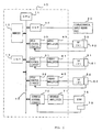
- a numerical control apparatus 10 comprises a CPU 11, and a memory 12, interfaces 13, 14, axis control circuits 30 to 32 of respective feed axes and a spindle control circuit 70, respectively connected to the CPU 11 through a bus 15.
- the CPU 11 reads out a system program stored in the memory 12 through the bus 15 and controls the whole numerical control apparatus according to the system program.
- the memory 12 includes ROM and RAM and stores various types of data inputted by an operator through a display/manual input means unit 20 comprising a display constituted of a CRT or a liquid crystal and a keyboard, as well as a processing program loaded through the interface 13 and a processing program inputted through the display/manual input means unit 20.
- the display/manual input means unit 20 includes a spindle override command switch. With an override commanded from the spindle override command switch, an override is applied to the spindle rotational speed commanded by the processing program for outputting.
- the axis control circuits 30 to 32 of the respective feed axes receive movement command amounts of the feed axes from the CPU 11 and output commands of the respective axes to servo amplifiers 40 to 42.
- the servo amplifiers 40 to 42 receive the commands to drive servo motors 50 to 52 of the respective axes of a machine (or an object to be controlled).
- the servo motors 50 to 52 of the respective axes include position/speed detectors 60 to 62 therein and feed back position and speed feedback signals from the position/speed detector to the axis control circuits 30 to 32 for position and speed feedback control.
- a spindle control circuit 70 receives a spindle rotation command and outputs a spindle speed signal to the spindle amplifier 71.
- the spindle amplifier 71 receives the spindle speed signal and rotates a spindle motor 72 at a commanded rotational speed.
- a position coder 73 feeds back a feedback pulse to the spindle control circuit 70 in synchronization with the rotation of the spindle motor 72. Thus, speed control is performed.
- the above-mentioned numerical control apparatus is different from conventional ones in that, in performing thread cutting by applying cutting feed to a workpiece in a plurality of times, thread cutting is started with cutting start timing controlled, when an override is applied to the spindle rotational speed.
- a spindle rotational speed (number of revolutions) command according to a processing program is denoted as Sc.
- a spindle rotational speed (number of revolutions) at the start of thread cutting, in case where an override is applied to the spindle rotational speed command Sc subsequent to several times of thread cuttings, is denoted as Sov.
- a thread pitch commanded by a processing program, a movement speed of the feed axis after a spindle override is applied, and response sensitivity of a servo system of the feed axis are taken as P, V and K, respectively.
- the feed axis of a cutting tool for performing a thread cutting is taken as Z-axis.
- thread cutting start time of the feed axis should be delayed by a delay time Td determined by the following expression (3) from a thread cutting start timing prior to applying an override (or from the time elapsed after the position coder for detecting spindle speed detects a one-turn signal).
- Td (nP - ⁇ Z)/V
- n is an integer satisfying n ⁇ ⁇ Z/P in the above (3) expression.
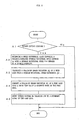
- FIG. 2 is a flow sheet of thread cutting processing of the CPU 11 of the numerical control apparatus 10, focusing on explanation of thread cutting operations.
- CPU 11 determines whether or not a command loaded from the processing program is a thread cutting command (step A1) and if not, program is finished without performing feed axis movement start control processing of the thread cutting. Processing for the loaded command is performed, however, this is omitted because it has no relation with the present invention.
- the CPU 11 upon loading a thread cutting command, compares the spindle rotational speed command Sc which is commanded by the processing program with the spindle rotational speed Sov which is changed according to a present override command, and determine the difference ⁇ S. That is, processing in the above expression (1) is performed (step A2).
- the step A2 constitutes a comparison means for determining a speed difference.
- step A3 By performing calculation from the spindle rotational speed difference ⁇ S using the above expression (2), the follow-up error variation ⁇ Z of the Z-axis as the feed axis is determined (step A3).
- the step A3 constitutes the calculation means for calculating the follow-up error variation.
- step A4 By performing calculation from the determined follow-up error variation ⁇ Z using the above expression (3), a delay time Td of feed axis (Z-axis) movement start for thread cutting is obtained (step A4).
- the step A4 constitutes the calculation means for converting the follow-up error variation ⁇ Z into delay time of movement start of the feed axis.
- the movement of the feed axis (Z-axis) for thread cutting is started behind the start time prior to application of override, by the determined delay time Td (step A5).
- the step A5 constitutes a delay control means for delaying the movement start of the feed axis. For example, if, before applying an override, the movement of the feed axis (Z-axis) for thread cutting is started behind a time t1 following the detection of one-turn signal feed-back from the position coder 73, the movement of the feed axis (Z-axis) in the following cycle will be started behind a time (t1+Td) following the detection of one-turn signal.
- the movement start of the feed axis for thread cutting is delayed by the time corresponding to the follow-up error variation of the feed axis, which is not dependent upon the output of a detector. Therefore, the movement start for thread cutting can be performed in an exact timing without being affected by the resolution of the detector, thus providing highly precise thread cutting.
Landscapes
- Engineering & Computer Science (AREA)
- Human Computer Interaction (AREA)
- Manufacturing & Machinery (AREA)
- Physics & Mathematics (AREA)
- General Physics & Mathematics (AREA)
- Automation & Control Theory (AREA)
- Mechanical Engineering (AREA)
- Numerical Control (AREA)
Applications Claiming Priority (2)
| Application Number | Priority Date | Filing Date | Title |
|---|---|---|---|
| JP2004133994 | 2004-04-28 | ||
| JP2004133994A JP2005313280A (ja) | 2004-04-28 | 2004-04-28 | 数値制御装置 |
Publications (1)
| Publication Number | Publication Date |
|---|---|
| EP1591848A2 true EP1591848A2 (de) | 2005-11-02 |
Family
ID=34940798
Family Applications (1)
| Application Number | Title | Priority Date | Filing Date |
|---|---|---|---|
| EP05252297A Withdrawn EP1591848A2 (de) | 2004-04-28 | 2005-04-13 | Numerisches Steuerungsgerät |
Country Status (4)
| Country | Link |
|---|---|
| US (1) | US7039493B2 (de) |
| EP (1) | EP1591848A2 (de) |
| JP (1) | JP2005313280A (de) |
| CN (1) | CN1689755A (de) |
Families Citing this family (17)
| Publication number | Priority date | Publication date | Assignee | Title |
|---|---|---|---|---|
| JP2005515910A (ja) * | 2002-01-31 | 2005-06-02 | ブレインテック カナダ インコーポレイテッド | シングルカメラ3dビジョンガイドロボティクスの方法および装置 |
| US20070073439A1 (en) * | 2005-09-23 | 2007-03-29 | Babak Habibi | System and method of visual tracking |
| CN100457390C (zh) * | 2006-04-18 | 2009-02-04 | 上海富安工厂自动化有限公司 | 数控轴位置精度的补偿方法 |
| US8437535B2 (en) | 2006-09-19 | 2013-05-07 | Roboticvisiontech Llc | System and method of determining object pose |
| US8090468B2 (en) * | 2008-09-05 | 2012-01-03 | Mag Ias, Llc | Multi-spindle phase controlled machining |
| US8559699B2 (en) | 2008-10-10 | 2013-10-15 | Roboticvisiontech Llc | Methods and apparatus to facilitate operations in image based systems |
| JP5482639B2 (ja) * | 2010-12-13 | 2014-05-07 | ブラザー工業株式会社 | 数値制御装置、制御プログラム及び記憶媒体 |
| CN102350548B (zh) * | 2011-09-30 | 2013-04-24 | 中国石化集团西南石油局管具公司 | 一种数控车床维修螺纹的对刀方法 |
| JP5852467B2 (ja) * | 2012-02-23 | 2016-02-03 | オークマ株式会社 | 数値制御装置 |
| KR101336520B1 (ko) | 2012-04-16 | 2013-12-03 | 현대위아 주식회사 | 나사절삭 가공장치 및 가공방법 |
| JP5969346B2 (ja) * | 2012-10-01 | 2016-08-17 | オークマ株式会社 | ねじ切り加工装置 |
| JP5908386B2 (ja) * | 2012-10-30 | 2016-04-26 | オークマ株式会社 | 工作機械 |
| CN103028890A (zh) * | 2012-12-27 | 2013-04-10 | 宁夏新瑞长城机床有限公司 | 石油钻杆螺纹自动修复方法 |
| US11550294B2 (en) | 2018-03-26 | 2023-01-10 | Siemens Aktiengesellschaft | Automatic diagnosis method and system for thread turning, data processing system and storage medium |
| US10981640B2 (en) * | 2018-07-16 | 2021-04-20 | The Boeing Company | Method and system for verification of tow end placement |
| CN112170993A (zh) * | 2020-08-22 | 2021-01-05 | 芽米科技成都有限公司 | 一种数控车床维修螺纹的对刀测量方法 |
| CN115599045B (zh) * | 2022-10-14 | 2025-09-23 | 珠海格力电器股份有限公司 | 刚性攻丝时主轴与进给z轴同步的控制方法、装置及系统 |
Family Cites Families (5)
| Publication number | Priority date | Publication date | Assignee | Title |
|---|---|---|---|---|
| US4079235A (en) * | 1976-12-27 | 1978-03-14 | Mcdonnell Douglas Corporation | Computer numerically controlled threadcutting machine tool |
| KR930001093B1 (ko) * | 1987-03-31 | 1993-02-15 | 부라더 고교 가부시키가이샤 | 나사 가공장치 |
| JPH0569275A (ja) * | 1991-09-12 | 1993-03-23 | Fanuc Ltd | 数値制御装置 |
| JP2000176789A (ja) | 1998-12-18 | 2000-06-27 | Okuma Corp | 数値制御装置 |
| JP3926739B2 (ja) * | 2002-12-27 | 2007-06-06 | オークマ株式会社 | ねじ切り加工制御方法及びその装置 |
-
2004
- 2004-04-28 JP JP2004133994A patent/JP2005313280A/ja active Pending
-
2005
- 2005-04-13 EP EP05252297A patent/EP1591848A2/de not_active Withdrawn
- 2005-04-26 CN CNA2005100678190A patent/CN1689755A/zh active Pending
- 2005-04-27 US US11/115,313 patent/US7039493B2/en not_active Expired - Fee Related
Also Published As
| Publication number | Publication date |
|---|---|
| JP2005313280A (ja) | 2005-11-10 |
| US7039493B2 (en) | 2006-05-02 |
| CN1689755A (zh) | 2005-11-02 |
| US20050246053A1 (en) | 2005-11-03 |
Similar Documents
| Publication | Publication Date | Title |
|---|---|---|
| US7039493B2 (en) | Numerical control apparatus | |
| JP4920785B2 (ja) | 数値制御方法及びその装置 | |
| US4884373A (en) | Numerically controlled machine tool | |
| US9869989B2 (en) | Numerical controller | |
| US9715225B2 (en) | Numerical controller for smoothing tool path in operation based on table format data | |
| KR102547810B1 (ko) | 선반 | |
| JPS6116568B2 (de) | ||
| US4810945A (en) | Numerical control feed device for machine tool | |
| US4941104A (en) | Numerical control apparatus for controlling a threading operation | |
| JPH0569275A (ja) | 数値制御装置 | |
| US6847857B2 (en) | Thread machining control method and apparatus therefor | |
| EP1688806B1 (de) | Numerische Steuerung | |
| US9841746B2 (en) | Numerical controller having function of controlling speed by superimposed control | |
| CN100496837C (zh) | 螺纹切削控制方法及其装置 | |
| US9519280B2 (en) | Numerical control device for machine tool | |
| JPH11143514A (ja) | 加工誤差チェックができる数値制御装置 | |
| JP7794961B2 (ja) | 数値制御装置およびコンピュータ読み取り可能な記憶媒体 | |
| US5654894A (en) | Gain changing control system for a threading apparatus | |
| US20010013267A1 (en) | Machine tool and control method therefor | |
| US20160004245A1 (en) | Numerical controller executing operation by table-format data | |
| US4583433A (en) | Turning control apparatus and method | |
| JP3648858B2 (ja) | 主軸同期制御方法及びその装置 | |
| JP3198010B2 (ja) | 工作機械の制御方法及び制御装置 | |
| JP2000231412A (ja) | インポジションチェック方法及びその装置 | |
| JP2010201571A (ja) | 可変ピッチネジの再加工方法及びその装置 |
Legal Events
| Date | Code | Title | Description |
|---|---|---|---|
| PUAI | Public reference made under article 153(3) epc to a published international application that has entered the european phase |
Free format text: ORIGINAL CODE: 0009012 |
|
| AK | Designated contracting states |
Kind code of ref document: A2 Designated state(s): AT BE BG CH CY CZ DE DK EE ES FI FR GB GR HU IE IS IT LI LT LU MC NL PL PT RO SE SI SK TR |
|
| AX | Request for extension of the european patent |
Extension state: AL BA HR LV MK YU |
|
| STAA | Information on the status of an ep patent application or granted ep patent |
Free format text: STATUS: THE APPLICATION HAS BEEN WITHDRAWN |
|
| 18W | Application withdrawn |
Effective date: 20070417 |