EP1591663B1 - Ölgedichtete Drehschieber-Vakuumpumpe und Verfahren zur Herstellung hiervon - Google Patents
Ölgedichtete Drehschieber-Vakuumpumpe und Verfahren zur Herstellung hiervon Download PDFInfo
- Publication number
- EP1591663B1 EP1591663B1 EP05101487A EP05101487A EP1591663B1 EP 1591663 B1 EP1591663 B1 EP 1591663B1 EP 05101487 A EP05101487 A EP 05101487A EP 05101487 A EP05101487 A EP 05101487A EP 1591663 B1 EP1591663 B1 EP 1591663B1
- Authority
- EP
- European Patent Office
- Prior art keywords
- membrane
- pump
- chamber
- casing
- vacuum pump
- Prior art date
- Legal status (The legal status is an assumption and is not a legal conclusion. Google has not performed a legal analysis and makes no representation as to the accuracy of the status listed.)
- Revoked
Links
Images
Classifications
-
- F—MECHANICAL ENGINEERING; LIGHTING; HEATING; WEAPONS; BLASTING
- F04—POSITIVE - DISPLACEMENT MACHINES FOR LIQUIDS; PUMPS FOR LIQUIDS OR ELASTIC FLUIDS
- F04C—ROTARY-PISTON, OR OSCILLATING-PISTON, POSITIVE-DISPLACEMENT MACHINES FOR LIQUIDS; ROTARY-PISTON, OR OSCILLATING-PISTON, POSITIVE-DISPLACEMENT PUMPS
- F04C29/00—Component parts, details or accessories of pumps or pumping installations, not provided for in groups F04C18/00 - F04C28/00
- F04C29/02—Lubrication; Lubricant separation
-
- F—MECHANICAL ENGINEERING; LIGHTING; HEATING; WEAPONS; BLASTING
- F04—POSITIVE - DISPLACEMENT MACHINES FOR LIQUIDS; PUMPS FOR LIQUIDS OR ELASTIC FLUIDS
- F04C—ROTARY-PISTON, OR OSCILLATING-PISTON, POSITIVE-DISPLACEMENT MACHINES FOR LIQUIDS; ROTARY-PISTON, OR OSCILLATING-PISTON, POSITIVE-DISPLACEMENT PUMPS
- F04C18/00—Rotary-piston pumps specially adapted for elastic fluids
- F04C18/30—Rotary-piston pumps specially adapted for elastic fluids having the characteristics covered by two or more of groups F04C18/02, F04C18/08, F04C18/22, F04C18/24, F04C18/48, or having the characteristics covered by one of these groups together with some other type of movement between co-operating members
- F04C18/34—Rotary-piston pumps specially adapted for elastic fluids having the characteristics covered by two or more of groups F04C18/02, F04C18/08, F04C18/22, F04C18/24, F04C18/48, or having the characteristics covered by one of these groups together with some other type of movement between co-operating members having the movement defined in group F04C18/08 or F04C18/22 and relative reciprocation between the co-operating members
- F04C18/344—Rotary-piston pumps specially adapted for elastic fluids having the characteristics covered by two or more of groups F04C18/02, F04C18/08, F04C18/22, F04C18/24, F04C18/48, or having the characteristics covered by one of these groups together with some other type of movement between co-operating members having the movement defined in group F04C18/08 or F04C18/22 and relative reciprocation between the co-operating members with vanes reciprocating with respect to the inner member
- F04C18/3441—Rotary-piston pumps specially adapted for elastic fluids having the characteristics covered by two or more of groups F04C18/02, F04C18/08, F04C18/22, F04C18/24, F04C18/48, or having the characteristics covered by one of these groups together with some other type of movement between co-operating members having the movement defined in group F04C18/08 or F04C18/22 and relative reciprocation between the co-operating members with vanes reciprocating with respect to the inner member the inner and outer member being in contact along one line or continuous surface substantially parallel to the axis of rotation
-
- F—MECHANICAL ENGINEERING; LIGHTING; HEATING; WEAPONS; BLASTING
- F04—POSITIVE - DISPLACEMENT MACHINES FOR LIQUIDS; PUMPS FOR LIQUIDS OR ELASTIC FLUIDS
- F04C—ROTARY-PISTON, OR OSCILLATING-PISTON, POSITIVE-DISPLACEMENT MACHINES FOR LIQUIDS; ROTARY-PISTON, OR OSCILLATING-PISTON, POSITIVE-DISPLACEMENT PUMPS
- F04C2220/00—Application
- F04C2220/10—Vacuum
-
- F—MECHANICAL ENGINEERING; LIGHTING; HEATING; WEAPONS; BLASTING
- F04—POSITIVE - DISPLACEMENT MACHINES FOR LIQUIDS; PUMPS FOR LIQUIDS OR ELASTIC FLUIDS
- F04C—ROTARY-PISTON, OR OSCILLATING-PISTON, POSITIVE-DISPLACEMENT MACHINES FOR LIQUIDS; ROTARY-PISTON, OR OSCILLATING-PISTON, POSITIVE-DISPLACEMENT PUMPS
- F04C2230/00—Manufacture
Definitions
- the present invention relates to an oil rotary vacuum pump of mechanical type and to a method of manufacturing said pump.
- Oil rotary pumps of mechanical type are generally used to obtain low vacuum conditions, that is a pressure range from atmospheric pressure to about 10 -1 Pa.
- Mechanical pumps include a casing, having a suction port and an exhaust port, within which a stator is provided defining a cylindrical chamber housing an eccentric circular rotor equipped with spring-loaded radial vanes. Said pumps are immersed into an oil bath, which has to refrigerate and lubricate the pump and to isolate if from the outside environment.
- Removable sealing members are known from the art.
- EP 845,599 refers to a sealing plug device for a refrigerant compressor, protecting the interior of the refrigerant compressor from dust, dirt and corrosion during storage and/or shipping.
- Said sealing plug device includes a plug element for sealing an inlet or outlet port of the refrigerant compressor and a base plate element screwed to the refrigerant compressor body for keeping the plug element in place.
- DE 35 42 420 discloses a connection device for the compressor capsule of a refrigerating machine which can be closed by a soldered metal cap when not in use.
- JP 7-139486 refers to a sealing plug for the suction / discharge tube of a freezer, suitable for suppressing the increase of hydrolysis of the oil during storage.
- a sealing plug should assure air-tightness and it is mounted by interference fit on the suction /discharge port of the freezer.
- JP 2002-161993 discloses an environmental friendly protection element for the end of a pipe comprising an adhesive portion and a non-adhesive portion which prevents the entrance of dust during transport and does not leave adhesive on the sealing surface when peeled off from the pipe.
- the methods employed in order to apply said membranes to said ports are chosen so that the membranes can be easily removed by the user before starting the pump.
- the material and the thickness of said membranes are chosen so that, even if the user forgot removing said membranes from said ports before using the pump, said membranes tear when the pump is started, leaving said ports free and without damaging the components of said pump or of devices connected thereto.
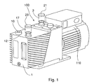
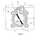
- mechanical oil pump 100 comprises an external casing 1 in which a second casing 2, having a cylindrical chamber 7 formed therein, is tightly arranged.
- Said chamber houses a cylindrical rotor 9, driven into rotation by a motor 110 connected to pump 100.
- the rotor has an axis parallel to the axis of said cylindrical chamber 7, but eccentrically located relative to the chamber axis.
- One or more radially movable radial vanes 11 are mounted onto said rotor 9 and are kept against the wall of said chamber 7 by means of springs 13.
- External casing 1 is filled with a suitable amount of oil, such that the second, tightly arranged casing 2 is immersed into an oil bath 19 acting as cooling and lubricating fluid.
- pump 100 is indeed manufactured so that a certain amount of oil can penetrate into chamber 7 and form a thin film ensuring tightness between vanes 11 of rotor 9 and the wall of said chamber 7.
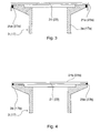
- the proper amount of oil is introduced into external casing 1, through a proper introduction port 12 sealed by a plug 10, in order to form oil bath 19, and suction and exhaust ports 3, 17 are sealed by means of a pair of membranes 21, 23 in view of the subsequent storage and shipping operations.
- said membranes 21, 23 can be applied to said suction and exhaust ports by gluing, so that a portion 21a, 23a of each said membrane 21, 23 is made to adhere to outer surface 3a, 17a of port 3, 17, respectively, through a layer 25a, 27a of a proper adhesive, thereby sealing said port.
- a portion 21b, 23b of said membranes 21, 23 is made to adhere to rim 3b, 17b of port 3, 17, respectively, through a layer 25b, 27b of said adhesive.
- the adhesive is selected so that it ensures a perfect tightness of said membranes on said ports, while allowing an easy and complete removal of said membranes by the user when the pump is to be used.
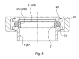
- a flange 29 is applied to the suction and exhaust ports of pump 100 and is kept in register with the respective port 3, 17 by means of a centring ring and a ring gasket 33. Said flange 29 can be kept pressed against the respective port by a locking nut 35 during the storage and shipping steps, and subsequently removed when the pump is to be used.
- membranes 21, 23 are applied to said centring ring 31 and not directly to suction or exhaust port 3, 17. More particularly, a peripheral portion 21c, 23c of each said membrane 21, 23 can be made to adhere to the inner surface of centring ring 31.
- This second embodiment entails important advantages.
- membranes 21, 23 could be secured to centring ring 31 even in a non-removable manner, since said ring 31 will be removed together with the respective membrane before starting the pump. Consequently, any conventional technique (gluing, welding, crimping, etc.) could be used for securing said membranes 21, 23 to the respective centring ring 31.
- said membranes 21, 23 do not undergo any deterioration when they are removed from suction and exhaust ports 3, 17, and therefore they can be used again in case of a possible further storage and/or shipping, by simply applying again the respective centring ring 31 and the respective flange 29 on each port.
- said membranes are made as very thin films, so that a moderate pressure difference is enough to tear them. In this way, even if the user forgot removing them before starting pump 100, when starting the pump the pressure exerted on said membranes because of rotor 7 being driven into rotation would be enough to make them tear, thus leaving ports 3, 17 of pump 100 unobstructed and without producing fragments that could damage the pump.
- the vacuum pump according to the invention attains the desired objects, in that it lets the user off the delicate operation of introducing the proper amount of oil into the pump when first starting the same pump.
- the provision of sealing membranes on the suction and exhaust ports of the pump according to the invention allows storing the pump for any time period and then shipping it without risks of oil leakage and consequent soiling of the pump of its packing.
Landscapes
- Engineering & Computer Science (AREA)
- Mechanical Engineering (AREA)
- General Engineering & Computer Science (AREA)
- Applications Or Details Of Rotary Compressors (AREA)
Claims (12)
- Eine Ölrotationsvakuumpumpe vom mechanischen Typ (100), die aufweist:- ein erstes Gehäuse (1), in dem ein Ölbad (19) festgelegt ist;- ein zweites Gehäuse (2), das innerhalb des ersten Gehäuses (1) angeordnet ist und in das Ölbad (19) eingetaucht ist;- eine Kammer (7), die innerhalb des zweiten Gehäuses festgelegt ist;- einen Rotor (9), der in der Kammer angeordnet ist und so ausgelegt ist, ein in der Kammer vorhandenes Gas zu komprimieren;- einen Saugkanal (5) zum Einführen eines Gases in die Kammer (7), wobei der Kanal an einer entsprechenden Saugöffnung (3) endet;- einen Auslasskanal (15) zum Auslassen des Gases aus der Kammer (7), wobei der Kanal an einer entsprechenden Auslassöffnung (17) endet;wobei die Saug- und/oder die Auslassöffnung (3, 17) ein entsprechendes entfernbares Dichtungselement (21, 23) zum Abdichten der Öffnungen umfassen, wenn die Pumpe nicht verwendet wird,
dadurch gekennzeichnet,
dass das entfernbare Dichtungselement eine Membran (21, 23) ist, wobei das Material und die Dicke der Membran derart sind, dass die Membran (21, 23) zerreißt, wenn die Pumpe verwendet wird. - Die Vakuumpumpe (100) nach Anspruch 1, dadurch gekennzeichnet, dass die Membran als sehr dünner Film hergestellt ist, so dass eine mäßige Druckdifferenz genügt, um sie zu zerreißen, wenn die Pumpe verwendet wird.
- Die Vakuumpumpe (100) nach Anspruch 2, dadurch gekennzeichnet, dass die Membran (21, 23) auf die Öffnungen (3, 17) durch Kleben aufgebracht ist.
- Die Vakuumpumpe (100) nach Anspruch 3, dadurch gekennzeichnet, dass die Membran (21, 23) an die Außenfläche (3a, 17a) der Öffnung (3, 17) geklebt ist.
- Die Vakuumpumpe (100) nach Anspruch 3, dadurch gekennzeichnet, dass die Membran (21, 23) an den Rand (3b, 17b) der Öffnung (3, 17) geklebt ist.
- Die Vakuumpumpe (100) nach Anspruch 1, dadurch gekennzeichnet, dass das Dichtungselement einen Flansch (29), einen Zentrierring (31), der zwischen dem Flansch und der Saug- und/oder Auslassöffnung (3, 17) angeordnet ist und mit einer Membran (21, 23) ausgestattet ist, und eine entfernbare Verriegelungsmutter (35) zum Fixieren des Flanschs (29) und des Zentrierrings (31) an der Saug- und/oder Auslassöffnung (3, 17) umfasst.
- Die Vakuumpumpe (100) nach Anspruch 6, dadurch gekennzeichnet, dass die Membran (21, 23) auf den Zentrierring (31) durch Kleben, Schweißen, Quetschen oder andere äquivalente Verfahren aufgebracht ist.
- Ein Verfahren zur Herstellung einer Ölrotationsvakuumpumpe vom mechanischen Typ (100), das die folgenden Schritte aufweist:- Herstellen einer Vakuumpumpe, die aufweist:- ein erstes Gehäuse (1);- ein zweites Gehäuse (2), das innerhalb des ersten Gehäuses (1) angeordnet ist;- eine Kammer (7), die innerhalb des zweiten Gehäuses festgelegt ist;- einen Rotor (9), der in der Kammer angeordnet ist und so ausgelegt ist, ein in der Kammer vorhandenes Gas zu komprimieren;- einen Saugkanal (5) zum Einführen eines Gases in die Kammer (7), wobei der Kanal an einer entsprechenden Saugöffnung (3) endet;- einen Auslasskanal (15) zum Auslassen des Gases aus der Kammer (7), wobei der Kanal an einer entsprechenden Auslassöffnung (17) endet;- Einführen einer Menge an Öl in das erste Gehäuse (1) durch eine entsprechende Öffnung (12), die ausreicht, um ein Ölbad (19) zu erzeugen, in das das zweite Gehäuse (2) eingetaucht ist;- Schließen der Öffnung (12);- Abdichten der Saugöffnung (3) und/oder der Auslassöffnung (17) mittels eines entsprechenden entfernbaren Dichtungselements (21, 23),
dadurch gekennzeichnet,
dass das entfernbare Dichtungselement eine Membran (21, 23) ist, wobei das Material und die Dicke der Membran derart sind, dass die Membran (21, 23) zerreißt, wenn die Pumpe verwendet wird. - Das Verfahren nach Anspruch 8, dadurch gekennzeichnet, dass die Membran als sehr dünner Film hergestellt ist, so dass eine mäßige Druckdifferenz genügt, um sie zu zerreißen, wenn die Pumpe verwendet wird.
- Das Verfahren nach Anspruch 9, dadurch gekennzeichnet, dass die Membran (21, 23) auf die Öffnung (3, 17) durch Kleben aufgebracht ist.
- Das Verfahren nach Anspruch 8, dadurch gekennzeichnet, dass das Dichtungselement einen Flansch (29), einen Zentrierring (31), der zwischen dem Flansch und der Saug- und/oder Auslassöffnung (3, 17) angeordnet ist und mit einer Membran (21, 23) ausgestattet ist, und eine entfernbare Verriegelungsmutter (35) zum Fixieren des Flanschs (29) und des Rings (31) an der Öffnung (3, 17) umfasst.
- Das Verfahren nach Anspruch 11, dadurch gekennzeichnet, dass die Membran (21, 23) auf die Öffnungen (3, 17) durch Kleben, Schweißen, Quetschen oder äquivalente Verfahren aufgebracht ist.
Applications Claiming Priority (2)
| Application Number | Priority Date | Filing Date | Title |
|---|---|---|---|
| ITTO20040268 | 2004-04-30 | ||
| IT000268A ITTO20040268A1 (it) | 2004-04-30 | 2004-04-30 | Pompa da vuoto meccanica rotativa ad olio e metodo di produzione di detta pompa |
Publications (3)
| Publication Number | Publication Date |
|---|---|
| EP1591663A1 EP1591663A1 (de) | 2005-11-02 |
| EP1591663B1 true EP1591663B1 (de) | 2011-06-15 |
| EP1591663B8 EP1591663B8 (de) | 2011-09-21 |
Family
ID=34938829
Family Applications (1)
| Application Number | Title | Priority Date | Filing Date |
|---|---|---|---|
| EP05101487A Revoked EP1591663B8 (de) | 2004-04-30 | 2005-02-28 | Ölgedichtete Drehschieber-Vakuumpumpe und Verfahren zur Herstellung hiervon |
Country Status (4)
| Country | Link |
|---|---|
| US (2) | US7588426B2 (de) |
| EP (1) | EP1591663B8 (de) |
| JP (1) | JP4632847B2 (de) |
| IT (1) | ITTO20040268A1 (de) |
Families Citing this family (14)
| Publication number | Priority date | Publication date | Assignee | Title |
|---|---|---|---|---|
| DE202006005682U1 (de) * | 2006-04-05 | 2006-06-14 | Lincoln Gmbh & Co. Kg | Schmiermittel- oder Hydraulikpumpe |
| DE102006058843A1 (de) | 2006-12-13 | 2008-06-19 | Pfeiffer Vacuum Gmbh | Vakuumpumpe |
| EP2020508A1 (de) * | 2007-07-30 | 2009-02-04 | VARIAN S.p.A. | Überdrucksicherung einer Vakuumpumpe |
| JP5218579B2 (ja) * | 2011-02-17 | 2013-06-26 | 株式会社豊田自動織機 | 圧縮機の流通路閉塞装置 |
| JP5746887B2 (ja) * | 2011-03-18 | 2015-07-08 | アルバック機工株式会社 | 油回転真空ポンプ |
| US20140363319A1 (en) * | 2013-06-07 | 2014-12-11 | Agilent Technologies, Inc | Rotary vane vacuum pump |
| CN105298839A (zh) * | 2015-10-13 | 2016-02-03 | 芜湖环球汽车配件有限公司 | 一种旋片式真空泵 |
| US10941772B2 (en) * | 2016-03-15 | 2021-03-09 | Emerson Climate Technologies, Inc. | Suction line arrangement for multiple compressor system |
| IT201800003151A1 (it) | 2018-02-28 | 2019-08-28 | Agilent Tech Inc A Delaware Corporation | Sistema di pompaggio per vuoto comprendente una pompa da vuoto ed il suo motore |
| IT201800003152A1 (it) | 2018-02-28 | 2019-08-28 | Agilent Tech Inc A Delaware Corporation | Metodo per il funzionamento di un sistema di pompaggio per vuoto e sistema di pompaggio per vuoto atto all'implementazione di detto metodo |
| US11421681B2 (en) | 2018-04-19 | 2022-08-23 | Emerson Climate Technologies, Inc. | Multiple-compressor system with suction valve and method of controlling suction valve |
| IT201900021330A1 (it) | 2019-11-15 | 2020-02-15 | Agilent Tech Inc A Delaware Corporation | Pompa da vuoto provvista di un serbatoio per l’olio |
| US12422173B2 (en) | 2022-08-19 | 2025-09-23 | Copeland Lp | Multiple-compressor system with oil balance control |
| USD1118702S1 (en) * | 2024-03-26 | 2026-03-17 | Testo SE & Co. KGaA | Vacuum pump |
Family Cites Families (14)
| Publication number | Priority date | Publication date | Assignee | Title |
|---|---|---|---|---|
| US2318346A (en) * | 1941-03-01 | 1943-05-04 | Selas Company | Rotary pump |
| US2782725A (en) * | 1954-05-18 | 1957-02-26 | Hojberg Laurencio Brochner | Rotary pump |
| US3580315A (en) * | 1965-03-11 | 1971-05-25 | Griffith Laboratories | Comminuting machine |
| JPS5840590U (ja) * | 1981-09-11 | 1983-03-17 | 日立工機株式会社 | 油回転真空ポンプの輸送時における排気口の封止構造 |
| DE3340198A1 (de) | 1983-11-07 | 1985-05-15 | Arthur Pfeiffer Vakuumtechnik Wetzlar Gmbh, 6334 Asslar | Oelgedichtete drehschiebervakuumpumpe mit antriebsmotor in einem gehaeuse |
| FR2555674B1 (fr) * | 1983-11-30 | 1986-03-28 | Cit Alcatel | Pompe a joint d'huile a palettes |
| GB8403370D0 (en) * | 1984-02-08 | 1984-03-14 | Lucas Ind Plc | Hydraulic fluid connector |
| DE3542420A1 (de) | 1985-11-30 | 1987-06-04 | Danfoss As | Anschlussvorrichtung fuer die verdichterkapsel einer kaeltemaschine |
| JPS62291488A (ja) * | 1986-06-11 | 1987-12-18 | Toshiba Corp | 油回転真空ポンプ |
| JPH0712702Y2 (ja) * | 1988-04-04 | 1995-03-29 | 株式会社ユニシアジェックス | 圧縮機 |
| JPH07139486A (ja) | 1993-11-12 | 1995-05-30 | Sanyo Electric Co Ltd | 冷媒圧縮機の封止栓装置 |
| DE19526303A1 (de) * | 1995-07-19 | 1997-01-23 | Leybold Ag | Ölgedichtete Drehschiebervakuumpumpe mit einer Ölversorgung |
| US5988223A (en) | 1996-11-28 | 1999-11-23 | Kabushiki Kaisha Toyoda Jidoshokki Seisakusho | Sealing plug device for a refrigerant compressor |
| JP2002161993A (ja) | 2000-11-27 | 2002-06-07 | Kitz Corp | 管端部用保護具 |
-
2004
- 2004-04-30 IT IT000268A patent/ITTO20040268A1/it unknown
-
2005
- 2005-02-28 EP EP05101487A patent/EP1591663B8/de not_active Revoked
- 2005-04-26 JP JP2005128507A patent/JP4632847B2/ja not_active Expired - Fee Related
- 2005-04-29 US US11/118,863 patent/US7588426B2/en not_active Expired - Fee Related
-
2009
- 2009-08-07 US US12/537,901 patent/US8118576B2/en not_active Expired - Fee Related
Also Published As
| Publication number | Publication date |
|---|---|
| EP1591663A1 (de) | 2005-11-02 |
| US8118576B2 (en) | 2012-02-21 |
| JP4632847B2 (ja) | 2011-02-16 |
| EP1591663B8 (de) | 2011-09-21 |
| JP2005315262A (ja) | 2005-11-10 |
| ITTO20040268A1 (it) | 2004-07-30 |
| US7588426B2 (en) | 2009-09-15 |
| US20090297383A1 (en) | 2009-12-03 |
| US20050244286A1 (en) | 2005-11-03 |
Similar Documents
| Publication | Publication Date | Title |
|---|---|---|
| US8118576B2 (en) | Oil rotary vacuum pump and manufacturing method thereof | |
| CN104364529B (zh) | 涡旋压缩机 | |
| US20220235772A1 (en) | Vacuum pumping system having an oil-lubricated vacuum pump | |
| JPS62243982A (ja) | 2段型真空ポンプ装置およびその運転方法 | |
| US9133846B2 (en) | Scroll fluid machine having a sealed compression chamber | |
| JP4544388B2 (ja) | スクロール圧縮機 | |
| JP2010053799A (ja) | スクリュー圧縮機 | |
| CN102734122A (zh) | 低温泵的盖结构、低温泵及其启动方法以及保管方法 | |
| US12305647B2 (en) | Hermetic type compressor | |
| US20190032659A1 (en) | Scroll compressor and air conditioning apparatus including the same | |
| CN115968426A (zh) | 压缩机 | |
| JP6359096B2 (ja) | 密閉型圧縮機の製造方法 | |
| JP2003120539A (ja) | 密閉型電動圧縮機およびその製造方法 | |
| WO2013069072A1 (ja) | 圧縮機及び圧縮機用密封栓 | |
| JP2012177353A (ja) | 多段圧縮式ロータリコンプレッサ及び圧縮式ロータリコンプレッサ | |
| JPH03105090A (ja) | スクロール形流体機械 | |
| JP3926696B2 (ja) | 気体圧縮機とその気密試験方法 | |
| CN111868385B (zh) | 密闭型压缩机 | |
| KR20190004200A (ko) | 냉매 누설 방지 구조가 개선된 압축기 | |
| KR100556941B1 (ko) | 스크롤 압축기의 토출가스 누설 방지 장치 | |
| KR20000001508U (ko) | 압축기 흡입구의 누설 방지장치 | |
| CN103415706A (zh) | 密闭型旋转压缩机 | |
| JPH07293467A (ja) | ベーン形真空ポンプ | |
| JP2583977B2 (ja) | 密閉型回転式圧縮機 | |
| GB2546897A (en) | Scroll compressor |
Legal Events
| Date | Code | Title | Description |
|---|---|---|---|
| PUAI | Public reference made under article 153(3) epc to a published international application that has entered the european phase |
Free format text: ORIGINAL CODE: 0009012 |
|
| AK | Designated contracting states |
Kind code of ref document: A1 Designated state(s): AT BE BG CH CY CZ DE DK EE ES FI FR GB GR HU IE IS IT LI LT LU MC NL PL PT RO SE SI SK TR |
|
| AX | Request for extension of the european patent |
Extension state: AL BA HR LV MK YU |
|
| 17P | Request for examination filed |
Effective date: 20060328 |
|
| AKX | Designation fees paid |
Designated state(s): DE FR GB IT |
|
| 17Q | First examination report despatched |
Effective date: 20070920 |
|
| GRAP | Despatch of communication of intention to grant a patent |
Free format text: ORIGINAL CODE: EPIDOSNIGR1 |
|
| GRAS | Grant fee paid |
Free format text: ORIGINAL CODE: EPIDOSNIGR3 |
|
| GRAA | (expected) grant |
Free format text: ORIGINAL CODE: 0009210 |
|
| AK | Designated contracting states |
Kind code of ref document: B1 Designated state(s): DE FR GB IT |
|
| REG | Reference to a national code |
Ref country code: GB Ref legal event code: FG4D |
|
| RAP2 | Party data changed (patent owner data changed or rights of a patent transferred) |
Owner name: AGILENT TECHNOLOGIES ITALIA S.P.A. |
|
| REG | Reference to a national code |
Ref country code: DE Ref legal event code: R096 Ref document number: 602005028497 Country of ref document: DE Effective date: 20110728 |
|
| RAP2 | Party data changed (patent owner data changed or rights of a patent transferred) |
Owner name: AGILENT TECHNOLOGIES ITALIA S.P.A. |
|
| PLBI | Opposition filed |
Free format text: ORIGINAL CODE: 0009260 |
|
| PLAX | Notice of opposition and request to file observation + time limit sent |
Free format text: ORIGINAL CODE: EPIDOSNOBS2 |
|
| 26 | Opposition filed |
Opponent name: OERLIKON LEYBOLD VACUUM GMBH Effective date: 20120314 |
|
| REG | Reference to a national code |
Ref country code: DE Ref legal event code: R026 Ref document number: 602005028497 Country of ref document: DE Effective date: 20120314 |
|
| REG | Reference to a national code |
Ref country code: GB Ref legal event code: 732E Free format text: REGISTERED BETWEEN 20120607 AND 20120613 |
|
| PLAF | Information modified related to communication of a notice of opposition and request to file observations + time limit |
Free format text: ORIGINAL CODE: EPIDOSCOBS2 |
|
| REG | Reference to a national code |
Ref country code: FR Ref legal event code: TP Owner name: AGILENT TECHNOLOGIES, INC., US Effective date: 20120627 |
|
| RAP2 | Party data changed (patent owner data changed or rights of a patent transferred) |
Owner name: AGILENT TECHNOLOGIES, INC. |
|
| PLBB | Reply of patent proprietor to notice(s) of opposition received |
Free format text: ORIGINAL CODE: EPIDOSNOBS3 |
|
| REG | Reference to a national code |
Ref country code: DE Ref legal event code: R082 Ref document number: 602005028497 Country of ref document: DE Representative=s name: KAHLER, KAECK & MOLLEKOPF, DE |
|
| REG | Reference to a national code |
Ref country code: DE Ref legal event code: R082 Ref document number: 602005028497 Country of ref document: DE Representative=s name: KAHLER, KAECK & MOLLEKOPF, DE |
|
| REG | Reference to a national code |
Ref country code: DE Ref legal event code: R082 Ref document number: 602005028497 Country of ref document: DE Representative=s name: BARTH, DANIEL, DIPL.-ING., DE Effective date: 20130109 Ref country code: DE Ref legal event code: R081 Ref document number: 602005028497 Country of ref document: DE Owner name: AGILENT TECHNOLOGIES, INC., US Free format text: FORMER OWNER: AGILENT TECHNOLOGIES ITALIA S.P.A., CERNUSCO SUL NAVIGLIO, IT Effective date: 20130109 Ref country code: DE Ref legal event code: R081 Ref document number: 602005028497 Country of ref document: DE Owner name: AGILENT TECHNOLOGIES, INC., US Free format text: FORMER OWNER: VARIAN S.P.A., LEINI, IT Effective date: 20110606 Ref country code: DE Ref legal event code: R082 Ref document number: 602005028497 Country of ref document: DE Representative=s name: BARTH, DANIEL, DIPL.-ING., DE Effective date: 20130108 Ref country code: DE Ref legal event code: R081 Ref document number: 602005028497 Country of ref document: DE Owner name: AGILENT TECHNOLOGIES, INC., US Free format text: FORMER OWNER: VARIAN S.P.A., LEINI, IT Effective date: 20130108 Ref country code: DE Ref legal event code: R081 Ref document number: 602005028497 Country of ref document: DE Owner name: AGILENT TECHNOLOGIES, INC., SANTA CLARA, US Free format text: FORMER OWNER: VARIAN S.P.A., LEINI, TURIN/TORINO, IT Effective date: 20130108 Ref country code: DE Ref legal event code: R081 Ref document number: 602005028497 Country of ref document: DE Owner name: AGILENT TECHNOLOGIES, INC., SANTA CLARA, US Free format text: FORMER OWNER: AGILENT TECHNOLOGIES ITALIA S.P.A., CERNUSCO SUL NAVIGLIO, MILANO, IT Effective date: 20130109 Ref country code: DE Ref legal event code: R081 Ref document number: 602005028497 Country of ref document: DE Owner name: AGILENT TECHNOLOGIES, INC., SANTA CLARA, US Free format text: FORMER OWNER: VARIAN S.P.A., LEINI, TURIN/TORINO, IT Effective date: 20110606 |
|
| REG | Reference to a national code |
Ref country code: DE Ref legal event code: R082 Ref document number: 602005028497 Country of ref document: DE Representative=s name: BARTH, DANIEL, DIPL.-ING., DE |
|
| REG | Reference to a national code |
Ref country code: DE Ref legal event code: R082 Ref document number: 602005028497 Country of ref document: DE Representative=s name: BARTH, DANIEL, DIPL.-ING., DE |
|
| PGFP | Annual fee paid to national office [announced via postgrant information from national office to epo] |
Ref country code: IT Payment date: 20140212 Year of fee payment: 10 |
|
| PG25 | Lapsed in a contracting state [announced via postgrant information from national office to epo] |
Ref country code: IT Free format text: LAPSE BECAUSE OF NON-PAYMENT OF DUE FEES Effective date: 20150228 |
|
| REG | Reference to a national code |
Ref country code: FR Ref legal event code: PLFP Year of fee payment: 12 |
|
| PLAB | Opposition data, opponent's data or that of the opponent's representative modified |
Free format text: ORIGINAL CODE: 0009299OPPO |
|
| R26 | Opposition filed (corrected) |
Opponent name: LEYBOLD GMBH Effective date: 20120314 |
|
| REG | Reference to a national code |
Ref country code: FR Ref legal event code: PLFP Year of fee payment: 13 |
|
| PGFP | Annual fee paid to national office [announced via postgrant information from national office to epo] |
Ref country code: DE Payment date: 20170221 Year of fee payment: 13 Ref country code: FR Payment date: 20170112 Year of fee payment: 13 |
|
| PGFP | Annual fee paid to national office [announced via postgrant information from national office to epo] |
Ref country code: GB Payment date: 20170222 Year of fee payment: 13 |
|
| RDAF | Communication despatched that patent is revoked |
Free format text: ORIGINAL CODE: EPIDOSNREV1 |
|
| STAA | Information on the status of an ep patent application or granted ep patent |
Free format text: STATUS: THE PATENT HAS BEEN GRANTED |
|
| REG | Reference to a national code |
Ref country code: DE Ref legal event code: R064 Ref document number: 602005028497 Country of ref document: DE Ref country code: DE Ref legal event code: R103 Ref document number: 602005028497 Country of ref document: DE |
|
| RDAG | Patent revoked |
Free format text: ORIGINAL CODE: 0009271 |
|
| STAA | Information on the status of an ep patent application or granted ep patent |
Free format text: STATUS: PATENT REVOKED |
|
| 27W | Patent revoked |
Effective date: 20180323 |
|
| GBPR | Gb: patent revoked under art. 102 of the ep convention designating the uk as contracting state |
Effective date: 20180323 |