EP1590643B1 - Palier de mesure comportant un systeme d'enregistrement et de traitement de donnees integre - Google Patents
Palier de mesure comportant un systeme d'enregistrement et de traitement de donnees integre Download PDFInfo
- Publication number
- EP1590643B1 EP1590643B1 EP04707873A EP04707873A EP1590643B1 EP 1590643 B1 EP1590643 B1 EP 1590643B1 EP 04707873 A EP04707873 A EP 04707873A EP 04707873 A EP04707873 A EP 04707873A EP 1590643 B1 EP1590643 B1 EP 1590643B1
- Authority
- EP
- European Patent Office
- Prior art keywords
- bearing
- measuring
- bearing according
- ring
- expansion
- Prior art date
- Legal status (The legal status is an assumption and is not a legal conclusion. Google has not performed a legal analysis and makes no representation as to the accuracy of the status listed.)
- Expired - Lifetime
Links
Images


Classifications
-
- F—MECHANICAL ENGINEERING; LIGHTING; HEATING; WEAPONS; BLASTING
- F16—ENGINEERING ELEMENTS AND UNITS; GENERAL MEASURES FOR PRODUCING AND MAINTAINING EFFECTIVE FUNCTIONING OF MACHINES OR INSTALLATIONS; THERMAL INSULATION IN GENERAL
- F16C—SHAFTS; FLEXIBLE SHAFTS; ELEMENTS OR CRANKSHAFT MECHANISMS; ROTARY BODIES OTHER THAN GEARING ELEMENTS; BEARINGS
- F16C19/00—Bearings with rolling contact, for exclusively rotary movement
- F16C19/52—Bearings with rolling contact, for exclusively rotary movement with devices affected by abnormal or undesired conditions
- F16C19/522—Bearings with rolling contact, for exclusively rotary movement with devices affected by abnormal or undesired conditions related to load on the bearing, e.g. bearings with load sensors or means to protect the bearing against overload
-
- F—MECHANICAL ENGINEERING; LIGHTING; HEATING; WEAPONS; BLASTING
- F16—ENGINEERING ELEMENTS AND UNITS; GENERAL MEASURES FOR PRODUCING AND MAINTAINING EFFECTIVE FUNCTIONING OF MACHINES OR INSTALLATIONS; THERMAL INSULATION IN GENERAL
- F16C—SHAFTS; FLEXIBLE SHAFTS; ELEMENTS OR CRANKSHAFT MECHANISMS; ROTARY BODIES OTHER THAN GEARING ELEMENTS; BEARINGS
- F16C33/00—Parts of bearings; Special methods for making bearings or parts thereof
- F16C33/30—Parts of ball or roller bearings
- F16C33/58—Raceways; Race rings
- F16C33/583—Details of specific parts of races
- F16C33/586—Details of specific parts of races outside the space between the races, e.g. end faces or bore of inner ring
-
- G—PHYSICS
- G01—MEASURING; TESTING
- G01L—MEASURING FORCE, STRESS, TORQUE, WORK, MECHANICAL POWER, MECHANICAL EFFICIENCY, OR FLUID PRESSURE
- G01L5/00—Apparatus for, or methods of, measuring force, work, mechanical power, or torque, specially adapted for specific purposes
- G01L5/0009—Force sensors associated with a bearing
- G01L5/0019—Force sensors associated with a bearing by using strain gages, piezoelectric, piezo-resistive or other ohmic-resistance based sensors
Definitions
- the invention relates to a measuring bearing with sensors for detecting physical quantities acting on the bearing and with electronic components for evaluation and transmission of the sensor output signals according to the preamble of patent claim 1.
- a sensor arrangement in a rolling bearing is known, which is suitable for determining physical quantities during the movement of a guided in the rolling bearing component.
- the sensors are designed as strain gauges, which are preferably mounted in a groove on the circumference of the fixed bearing shell, the latter may be formed as an inner or outer bearing shell of a rolling bearing.
- the strain gauges on an insulating layer on a metallic intermediate carrier such. As a platelet.
- Another, designed as a circuit substrate carrier material surrounds said subcarrier with the strain gauges and is used to hold electronic components and interconnects. For attachment of the intermediate carrier with the strain gauges and the circuit substrate in the groove of the bearing these are pressed or welded there.
- strain gauges can be applied to the metallic intermediate carrier in an axial and tangential full or half bridge circuit.
- this publication discloses that with the electronic modules signal evaluation and signal transmission to other measuring points or other evaluation circuits or to a connector occurs.
- the signal transmission in this known measuring bearing can be carried out serially via a digital or an analog bus, which is arranged for example in a motor vehicle.
- this known measuring bearing has a comparatively high and also very advantageous degree of integration due to the arrangement of strain gauges and electronic components in a recess in the groove of the bearing ring, a relatively wide groove is required for this construction.
- the usable area for the sensor is too small or reduced. Since the groove is to be kept as small as possible in such a bearing ring to avoid component weakening, the implementation of the DE 101 36 438 A1 known arrangement in a marketable product less likely. This technical problem occurs especially in axially very narrow bearings.
- the object of the invention is to provide a from the DE 101 36 438 A1 Known measuring bearing to improve such that the degree of integration of the measurement and evaluation arrangement is further increased in order to accommodate them in a narrow and space-saving recess in one of the bearing rings can.
- the invention is therefore based on a generic measuring bearing, in which strain gauges are arranged in a recess on the circumference of one of the bearing rings.
- electrical conductor tracks and electronic components for evaluating the output signals of the strain gauges and for the transmission of intermediate and final results are arranged in this recess on a carrier material, wherein the strain gauges are connected to the electronic components via electrical conductor tracks.
- such a measuring bearing is now developed so that the strain gauges are arranged radially below (outer ring) and / or above the carrier material (inner ring).
- This design ensures that the measurement and evaluation system of strain gauges, printed conductors and electronic components located in the recess on the circumference of the bearing ring is now constructed in several layers and thus requires significantly less surface area than the known measuring bearing. Therefore, with the same recess or groove width either more measuring and evaluation technology can be accommodated in this recess, or it is only a particularly small recess on the circumference of the bearing ring necessary to accommodate a specific measurement and evaluation system can or the depth of the groove can be made very low. Another advantage is that the entire groove width can be used for the strain gauges and thus the deformations can be better detected.
- said measuring and evaluation system is preferably formed in a circumferential recess on the stationary bearing ring.
- the conventionally known systems telemetry, inductive coupling, sliding contacts
- telemetry, inductive coupling, sliding contacts are to be used for data and energy transmission.
- the strain gauges directly are applied to the surface of at least one of the bearing rings.
- This application of the strain gauges on the surface of a bearing ring in the region of its circumferential recess is preferably achieved by sputtering.
- the formation of surface structures on plan bodies by the vapor deposition of preferably conductors or semiconductors under vacuum is known per se, new and technically difficult to cope, however, is the sputtering example of thin-film strain gauges on a curved surface, just like the circumferential recess of a Bearing ring is.
- the strain gauges are applied to a bearing ring made of an electrically non-conductive or poorly conductive material (eg., Plastic) directly on the surface of the bearing ring or a bearing ring made of electrically conductive material on a disposed therebetween silicon dioxide layer.
- an electrically non-conductive or poorly conductive material eg., Plastic
- strain gauges For the electrical connection of the strain gauges with at least one of the conductor tracks and / or directly with the electronic components connecting wires (bonding wires) are provided in a further useful embodiment of the invention, which penetrate recesses in the substrate for the electronic components.
- This carrier material is preferably designed as a flexible plastic film.
- the recesses of the substrate and / or arranged in the recess on the circumference of the bearing ring blocks with a flexible and electrically non-conductive covering material is covered.
- This cover material is preferably designed as an organic plastic potting compound, which can be covered quickly and clean the covering zones.
- the electrical and electronic components for determining the rotational speed and / or the direction of rotation of a bearing body in the bearing, acting on the bearing radial and axial force, the direction of force, the bearing noise, the storage temperature and an optionally occurring unbalance are formed.
- the electronic components can be constructed as individual discrete electronic components such as operational amplifiers, capacitors, resistors or even as complex and very small microcomputers. In addition, it is considered useful for certain applications when a plurality of microcomputers are arranged in the peripheral recess of the bearing ring and connected via data lines, via which a digital data exchange can take place.
- At least one of the electronic components has a connection point via which raw data and / or processed information about the current physical state of the bearing and / or the component connected to the bearing to at least one separate display located outside the warehouse.
- Data storage and / or data processing device are leitbar.
- an adhesive to be applied between the silicon dioxide layer on the circumferential groove in the bearing ring and the strain gauges and / or the printed conductors, which adhesive acts as a binder between the silicon dioxide-coated surface and precisely these electrical components.
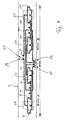
- FIG. 1 shows a rough overview of a cross section through a Meß65lzlager, which consists essentially of an outer ring 1, an inner ring 2 and arranged between these two bearing rings 2, 3 rolling elements 3.
- FIG. 1 as well as the FIG. 2 with its top view of the peripheral surface of the outer ring 1 can be removed that on the outer circumference of the outer ring 1, an annular groove 4 is formed in the at measuring points 5, 6 sensors 7, 8 are arranged for detecting, for example, a force F.
- the groove in the outer ring 1 need not necessarily be formed as a circumferential groove, since the said sensors 7, 8 can also be mounted in axially aligned grooves on the circumference of one of the two bearing rings 1, 2.
- the sensors 7, 8 are designed as strain gauges and interconnected with other electrical resistors 9, 10, 11, 27, 28, 29 in at least one measuring bridge.
- these strain gauges each have a variable electrical resistance, which responds to a pressure load with the force F on the outer ring 1 with a resistance change in a Vorbeirollen the rolling element 3, which can be tapped at the measuring bridge as a measurement signal.
- a measuring bearing according to the invention is created in that the strain gauges are mounted in a radial plane on the bearing ring, from the radial plane the electronic components and interconnects of the flexible film is different.
- This other radial plane of the strain gauges is arranged in the embodiment shown here below the radial plane of the electronic components and the interconnects, so that the space requirement of this highly integrated measurement and evaluation significantly reduced. This structure will be discussed in more detail later.
- FIG. 4 is first shown in a settlement of the circumferential groove 4 of the outer bearing ring 1, as the strain gauges 7, 9, 10, 11 of a first sensor A and strain gauges 8, 27, 28, 29 of a second sensor B in a row behind one another in the region of the trajectory of the rolling elements 22, 23, 24, 25 are arranged.
- These strain gauges are sputtered in this embodiment on a silicon dioxide-coated surface of the circumferential groove of the bearing outer ring and thus formed as a thin-film sensors.
- the strain gauges 7, 9, 10, 11 and the strain gauges 8, 27, 28, 29 of the two sensors A, B are each interconnected via likewise sputtered conductor tracks 21, 30 to measuring bridges, whose of the passing rolling elements 22, 23, 24, 25 modulated measuring signals at contact points 20, 26 can be tapped off.
- contact points 19 for the voltage supply of the strain gages 7, 9, 10, 11 or 8, 27, 28, 29 are sputtered in the region of these measuring signal contact points 20, 26.
- an adhesive 13 is applied, which carries a flexible carrier material 14, on the radially outwardly facing the electrical conductors 16 and the electronic components 17 (such as microcomputer) are preferably also glued or sputtered.
- the strain gauges 7, 9, 10, 11 and 8, 27, 28, 29 are arranged together with their interconnects 21, 30 and contact points 19, 20, 26, of which, however, only a truncated strain gauge 7 and the contact point 20 are shown here.
- connection points 19, 20, 26 of the sensors A, B him range of recesses 32, 33 not from the substrate 14th Covered so that with connecting wires (bonding wires) 15 electrical connections between the said components are created.
- These connecting wires 15 are preferably formed as contacted by a laser beam or liquid metal filaments, which are drawn from one contact point to the next contact point.
- a cover 18 is arranged, which is flexible and electrically insulating for a reliable provides mechanical and electrical protection of the carrier film 14 and the electrical and electronic components.
- the measuring bearing according to the invention is characterized by its very space-saving design, so that appropriate measurement and evaluation systems can be installed in very narrow rolling bearings, which were previously not feasible as a measuring bearing.
- a bearing can be accommodated with the radially layered measuring and evaluation system in a very narrow circumferential groove, so that a component weakening is reduced to the lowest possible degree.
- thin-film construction and flat-building measures thin ASIC'S
- the depth of the groove and thus the component weakening is largely reduced.
Landscapes
- Engineering & Computer Science (AREA)
- General Engineering & Computer Science (AREA)
- Mechanical Engineering (AREA)
- Chemical & Material Sciences (AREA)
- Analytical Chemistry (AREA)
- Physics & Mathematics (AREA)
- General Physics & Mathematics (AREA)
- Force Measurement Appropriate To Specific Purposes (AREA)
- Rolling Contact Bearings (AREA)
- Electrical Discharge Machining, Electrochemical Machining, And Combined Machining (AREA)
- Pharmaceuticals Containing Other Organic And Inorganic Compounds (AREA)
- Arrangements For Transmission Of Measured Signals (AREA)
Claims (16)
- Palier de mesure doté d'une découpe (4) à la périphérie d'au moins l'une de ses bagues de palier (1, 2), de rubans de mesure d'allongement (7, 8, 9, 10, 11, 27, 28, 29) disposés dans la découpe (4), de pistes conductrices (16) disposées sur un matériau de support (14) et de composants électroniques (17) d'évaluation et de transmission des signaux de sortie des rubans de mesure d'allongement, les rubans de mesure d'allongement étant reliés électriquement aux pistes électriquement conductrices (16) qui conduisent aux composants électroniques (17),
caractérisé en ce que
les rubans de mesure d'allongement (7, 8, 9, 10, 11, 27, 28, 29) sont fixés sur la bague de palier (1, 2) dans un plan radial situé en dessous pour la bague extérieure (1) et/ou au-dessus pour la bague intérieure (2) du plan radial (31) du matériau de support (14) et des pistes conductrices (16) et composants électroniques (17) situés sur ce dernier. - Palier de mesure selon la revendication 1, caractérisé en ce qu'au moins dans la zone occupée par la découpe (4), la surface de la bague de palier (1) présente une couche d'isolation, par exemple une couche (12) de dioxyde de silicium.
- Palier de mesure selon la revendication 2, caractérisé en ce qu'un adhésif (13) est appliqué au-dessus de la couche d'isolation (12) prévue sur la bague de palier (1) et porte les rubans de mesure d'allongement (7, 8, 9, 10, 11, 27, 28, 29), le matériau de support (14) et/ou les conducteurs électriques (21, 30).
- Palier de mesure selon au moins l'une des revendications 1 à 3, caractérisé en ce que les rubans de mesure d'allongement (7, 8, 9, 10, 11, 27, 28, 29), les conducteurs électriques (16, 21, 30) et/ou les composants électroniques (17) sont déposés par pulvérisation directe sur la surface de la découpe (4) de la bague de palier (1) ou sur la couche (12) de dioxyde de silicium.
- Palier de mesure selon au moins l'une des revendications 1 à 3, caractérisé en ce que les rubans de mesure d'allongement (7, 8, 9, 10, 11, 27, 28, 29) sont reliés par des fils de liaison (fils collés 15) aux pistes conductrices (16) ou directement aux composants électroniques (17).
- Palier de mesure selon au moins l'une des revendications précédentes, caractérisé en ce que des découpes (32, 33) sont prévues dans la zone du matériau de support (14) occupée par les fils de liaison (15).
- Palier de mesure selon la revendication 1 ou la revendication 6, caractérisé en ce que le matériau de support (14) est flexible.
- Palier de mesure selon la revendication 7, caractérisé en ce que le matériau de support (14) est constitué d'une feuille de matière synthétique.
- Palier de mesure selon au moins l'une des revendications précédentes, caractérisé en ce que les découpes (32, 33) de la zone occupée par le matériau de support (14) et/ou l'ensemble de la découpe (rainure 4) ménagée dans la bague de palier (1) sont recouvertes par un matériau de recouvrement (18) flexible et électriquement non conducteur.
- Palier de mesure selon la revendication 9, caractérisé en ce que le matériau de recouvrement (18) est configuré comme pâte organique plastique de scellement.
- Palier de mesure selon au moins l'une des revendications précédentes, caractérisé en ce qu'il est configuré comme palier de roulement dont les bagues de palier sont constituées de métal ou de matière synthétique.
- Palier de mesure selon la revendication 11, caractérisé en ce que la découpe (rainure 4) est formée sur la bague de palier fixe et de préférence sur la bague extérieure fixe de palier (1).
- Palier de mesure selon au moins l'une des revendications précédentes, caractérisé en ce que ces composants électriques et électroniques (17) sont configurés pour déterminer la vitesse de rotation et/ou le sens de rotation d'un corps monté dans le palier, de la force radiale et de la force axiale qui agissent sur le palier, de la direction de la force, du bruit du palier, de la température du palier et d'un éventuel balourd.
- Palier de mesure selon la revendication 13, caractérisé en ce que les composants électroniques comprennent au moins un micro-ordinateur (17).
- Palier de mesure selon la revendication 14, caractérisé en ce que plusieurs micro-ordinateurs (17) sont reliés les uns aux autres par des conducteurs de données qui permettent un échange de données de préférence numériques.
- Palier de mesure selon au moins l'une des revendications 13 à 15, caractérisé en ce qu'au moins l'un des composants électroniques (17) dispose d'un emplacement de raccordement par lequel les données brutes et/ou des informations traitées concernant l'état physique instantané du palier et/ou du composant relié au palier peuvent être amenées à au moins un dispositif séparé d'affichage, de mémoire de données et/ou de traitement de données situé à l'extérieur du palier.
Applications Claiming Priority (3)
| Application Number | Priority Date | Filing Date | Title |
|---|---|---|---|
| DE10304592 | 2003-02-05 | ||
| DE10304592A DE10304592A1 (de) | 2003-02-05 | 2003-02-05 | Messlager mit integriertem Datenerfassungs- und verarbeitungssystems |
| PCT/DE2004/000184 WO2004070337A1 (fr) | 2003-02-05 | 2004-02-04 | Palier de mesure comportant un systeme d'enregistrement et de traitement de donnees integre |
Publications (2)
| Publication Number | Publication Date |
|---|---|
| EP1590643A1 EP1590643A1 (fr) | 2005-11-02 |
| EP1590643B1 true EP1590643B1 (fr) | 2009-04-22 |
Family
ID=32730759
Family Applications (1)
| Application Number | Title | Priority Date | Filing Date |
|---|---|---|---|
| EP04707873A Expired - Lifetime EP1590643B1 (fr) | 2003-02-05 | 2004-02-04 | Palier de mesure comportant un systeme d'enregistrement et de traitement de donnees integre |
Country Status (6)
| Country | Link |
|---|---|
| US (1) | US7568842B2 (fr) |
| EP (1) | EP1590643B1 (fr) |
| JP (1) | JP4535290B2 (fr) |
| AT (1) | ATE429633T1 (fr) |
| DE (2) | DE10304592A1 (fr) |
| WO (1) | WO2004070337A1 (fr) |
Families Citing this family (28)
| Publication number | Priority date | Publication date | Assignee | Title |
|---|---|---|---|---|
| DE10303876A1 (de) * | 2003-01-31 | 2004-08-12 | Fag Kugelfischer Ag | Messanordnung, Wälzlager und Verfahren zur Ermittlung der Bewegungsrichtung eines Wälzlagerbauteils |
| DE10323889A1 (de) * | 2003-05-27 | 2004-12-16 | Ehrfeld Mikrotechnik Ag | Wälzlager mit Polymerelektronik |
| DE10344234A1 (de) | 2003-09-24 | 2005-05-12 | Fag Kugelfischer Ag | Datenerfassungs- und Verarbeitungssystem für ein Wälzlager und Wälzlager mit einem solchen System |
| JP2007032705A (ja) * | 2005-07-27 | 2007-02-08 | Jtekt Corp | センサ付き転がり軸受装置及び歪みセンサ |
| JP2006307935A (ja) * | 2005-04-27 | 2006-11-09 | Jtekt Corp | センサ付転がり軸受装置 |
| JP5147254B2 (ja) * | 2007-02-08 | 2013-02-20 | Ntn株式会社 | センサ付車輪用軸受 |
| KR101428829B1 (ko) | 2007-03-12 | 2014-08-11 | 아크티에볼라겟 에스케이에프 | 센서식 베어링 유닛 |
| EP1988377B1 (fr) * | 2007-05-01 | 2012-11-07 | Jtekt Corporation | Dispositif de roulement à rouleaux avec capteur |
| JP5424565B2 (ja) * | 2008-02-15 | 2014-02-26 | Ntn株式会社 | センサ付車輪用軸受 |
| FR2947643B1 (fr) * | 2009-07-06 | 2011-08-19 | Renault Sa | Systeme de commande pour machine tournante a roulement instrumente |
| EP2462616A1 (fr) * | 2009-08-05 | 2012-06-13 | Continental Teves AG & Co. oHG | Agencement de capteurs et puce avec pattes de fixation supplémentaires |
| DE102011103848A1 (de) * | 2011-05-27 | 2012-11-29 | Deutsches Zentrum für Luft- und Raumfahrt e.V. | Sensoreinrichtung |
| CN105122025A (zh) * | 2012-12-14 | 2015-12-02 | Skf公司 | 光纤传感器组件 |
| DE102013004678A1 (de) * | 2013-03-19 | 2014-09-25 | Continental Teves Ag & Co. Ohg | Leiterplatte zum Anbinden eines Verformungssensor an eine Signalverarbeitungsschaltung |
| JP5670539B2 (ja) * | 2013-11-11 | 2015-02-18 | アクティエボラゲット・エスコーエッフ | センサを備えたベアリングユニット |
| JP6507372B2 (ja) * | 2014-01-16 | 2019-05-08 | パナソニックIpマネジメント株式会社 | 電気素子と温度検知器とを備えた電子装置 |
| DE102014212530A1 (de) * | 2014-06-30 | 2015-12-31 | Schaeffler Technologies AG & Co. KG | Sensoranordnung sowie Wälzlager mit einer solchen |
| DE102014217787A1 (de) * | 2014-09-05 | 2016-03-10 | Schaeffler Technologies AG & Co. KG | Wälzlager mit einer elektrischen Schaltung sowie Herstellungsverfahren einer elektrischen Schaltung für ein Wälzlager |
| JP6374805B2 (ja) * | 2015-02-27 | 2018-08-15 | 日立金属株式会社 | トルク検出装置、及びトルク検出方法 |
| DE102017218878A1 (de) * | 2016-11-07 | 2018-05-24 | Aktiebolaget Skf | Verkabeltes Lager |
| USD797854S1 (en) * | 2017-05-25 | 2017-09-19 | Marc Puglisi | Bearing pen |
| DE102017123474A1 (de) | 2017-10-10 | 2019-04-11 | Schaeffler Technologies AG & Co. KG | Verfahren zur Detektion von Lagerschäden und Lageranordnung |
| DE102018128648A1 (de) * | 2018-11-15 | 2020-05-20 | Schaeffler Technologies AG & Co. KG | Sensorlager, Fahrzeug mit diesem und Verfahren zum Auswerten von Messdaten aus dem Sensorlager |
| JP7201542B2 (ja) * | 2019-06-21 | 2023-01-10 | ミネベアミツミ株式会社 | 転がり軸受、回転装置、軸受監視装置、軸受監視方法 |
| JP6986050B2 (ja) * | 2019-06-21 | 2021-12-22 | ミネベアミツミ株式会社 | 軸受監視装置、軸受監視方法 |
| DE102020112442A1 (de) | 2020-05-07 | 2021-11-11 | Schaeffler Technologies AG & Co. KG | Sensorlager, Fahrzeug mit diesem und Verfahren zum Auswerten von Messdaten aus dem Sensorlager |
| JP7512767B2 (ja) * | 2020-08-25 | 2024-07-09 | 株式会社ジェイテクト | センサ付き機械部品及びセンサ付き機械部品の製造方法 |
| DE102023209853A1 (de) * | 2023-10-10 | 2025-04-10 | Aktiebolaget Skf | Lagervorrichtung und zugehörige Maschine |
Family Cites Families (13)
| Publication number | Priority date | Publication date | Assignee | Title |
|---|---|---|---|---|
| DE2746937C2 (de) * | 1977-10-17 | 1986-11-06 | Gerhard Dr.-Ing. 1000 Berlin Lechler | Kraftmeßeinrichtung |
| JPS5842941A (ja) * | 1981-09-07 | 1983-03-12 | Toshiba Corp | ロ−ドセル |
| JPH02124322U (fr) * | 1989-03-24 | 1990-10-12 | ||
| SE8904082D0 (sv) | 1989-12-04 | 1989-12-04 | Skf Nova Ab | Hjullagerenhet |
| US5140849A (en) * | 1990-07-30 | 1992-08-25 | Agency Of Industrial Science And Technology | Rolling bearing with a sensor unit |
| DE19747001C2 (de) | 1997-10-24 | 2000-02-24 | Mannesmann Vdo Ag | Dehnungsmeßstreifen sowie ein mit diesen Dehnungsmeßstreifen hergestellter mechanisch-elektrischer Wandler |
| DE19814261A1 (de) * | 1998-03-31 | 1999-10-14 | Mannesmann Vdo Ag | Dehnungsempfindlicher Widerstand |
| US5952587A (en) * | 1998-08-06 | 1999-09-14 | The Torrington Company | Imbedded bearing life and load monitor |
| EP1358453B1 (fr) * | 2000-04-10 | 2007-11-21 | The Timken Company | Ensemble roulement equipe d'un capteur pour la surveillance de charges |
| DE10017572B4 (de) * | 2000-04-10 | 2008-04-17 | INSTITUT FüR MIKROTECHNIK MAINZ GMBH | Wälzlager mit fernabfragbaren Erfassungseinheiten |
| US6687623B2 (en) * | 2000-05-17 | 2004-02-03 | Ntn Corporation | Real time bearing load sensing |
| DE10136438A1 (de) * | 2000-08-22 | 2002-03-07 | Bosch Gmbh Robert | Sensoranordnung in einem Wälzlager und Verfahren zur Auswertung des Sensorsignals |
| EP1203960B2 (fr) * | 2000-11-06 | 2018-02-07 | Nsk Ltd | Dispositif de palier à roulement et anneau avec un capteur pour le dispositif de palier à roulement |
-
2003
- 2003-02-05 DE DE10304592A patent/DE10304592A1/de not_active Withdrawn
-
2004
- 2004-02-04 AT AT04707873T patent/ATE429633T1/de not_active IP Right Cessation
- 2004-02-04 DE DE502004009388T patent/DE502004009388D1/de not_active Expired - Lifetime
- 2004-02-04 JP JP2006501489A patent/JP4535290B2/ja not_active Expired - Fee Related
- 2004-02-04 WO PCT/DE2004/000184 patent/WO2004070337A1/fr not_active Ceased
- 2004-02-04 US US10/544,597 patent/US7568842B2/en not_active Expired - Fee Related
- 2004-02-04 EP EP04707873A patent/EP1590643B1/fr not_active Expired - Lifetime
Also Published As
| Publication number | Publication date |
|---|---|
| WO2004070337A1 (fr) | 2004-08-19 |
| US7568842B2 (en) | 2009-08-04 |
| US20060257060A1 (en) | 2006-11-16 |
| EP1590643A1 (fr) | 2005-11-02 |
| JP4535290B2 (ja) | 2010-09-01 |
| ATE429633T1 (de) | 2009-05-15 |
| JP2006518841A (ja) | 2006-08-17 |
| DE10304592A1 (de) | 2004-08-19 |
| DE502004009388D1 (de) | 2009-06-04 |
Similar Documents
| Publication | Publication Date | Title |
|---|---|---|
| EP1590643B1 (fr) | Palier de mesure comportant un systeme d'enregistrement et de traitement de donnees integre | |
| EP1627213B1 (fr) | Palier a roulement comportant une electronique polymere | |
| DE10243095B4 (de) | Wälzlager mit intergrierter Zustandsmessung | |
| WO2012041498A1 (fr) | Résolveur capacitif | |
| EP2527809A1 (fr) | Dispositif de détection | |
| EP3728880B1 (fr) | Dispositif et procédé de détermination d'une grandeur d'état | |
| WO2005031296A1 (fr) | Systeme d'acquisition et de traitement de donnees pour un palier a roulement et palier a roulement pourvu d'un tel systeme | |
| DE102018128648A1 (de) | Sensorlager, Fahrzeug mit diesem und Verfahren zum Auswerten von Messdaten aus dem Sensorlager | |
| DE102012019572B3 (de) | Drehgeber mit verbesserter Wellenisolierung | |
| DE102004054201A1 (de) | Wälzlager mit in der Lagerringstirnseite integrierten Sensoren | |
| EP1924834A1 (fr) | Systeme capteur | |
| DE10144054A1 (de) | Torsionsmodul für eine Drehmomenterfassungseinrichtung | |
| DE102010024806B4 (de) | Drehmoment-Messeinrichtung und Verfahren zur Drehmomentmessung | |
| DE2505427B2 (de) | Flaechige mess- und schirmelektrode mit kapazitivem signalabgriff fuer induktive durchflussmesser | |
| EP2143982B1 (fr) | Agencement d'étanchéité pour une bride de liaison | |
| DE112019005064T5 (de) | Lagervorrichtung und Vorbelastungssensor | |
| DE102008008727A1 (de) | Lager mit Positionsgeber | |
| EP3231045B1 (fr) | Système de couplage rotatif comprenant un ensemble de bagues collectrices pourvu d'un système rotorique | |
| DE4034991A1 (de) | Messeinrichtung zum elektrischen erfassen eines stellwinkels | |
| DE102016116181A1 (de) | Ein- oder mehrachsige Kraftmesseinrichtung mit kurzer Verformungszone | |
| EP0640813B1 (fr) | Capteur de force à barre annulaire avec des rainures annulaires pour le réglage nominal de la charge | |
| DE102016218652A1 (de) | Lageranordnung mit darin eingebauter elektrischer Leitung zur Bereitstellung von mehreren Betriebsspannungen | |
| WO2003023345A1 (fr) | Module a torsion pour dispositif de mesure de couple | |
| EP4249855B1 (fr) | Capteur de rotation et procédé de fonctionnement d'un capteur de rotation | |
| DE102020128602A1 (de) | Spannungswellengetriebe und elastisches Übertragungselement hierfür |
Legal Events
| Date | Code | Title | Description |
|---|---|---|---|
| PUAI | Public reference made under article 153(3) epc to a published international application that has entered the european phase |
Free format text: ORIGINAL CODE: 0009012 |
|
| 17P | Request for examination filed |
Effective date: 20050705 |
|
| AK | Designated contracting states |
Kind code of ref document: A1 Designated state(s): AT BE BG CH CY CZ DE DK EE ES FI FR GB GR HU IE IT LI LU MC NL PT RO SE SI SK TR |
|
| AX | Request for extension of the european patent |
Extension state: AL LT LV MK |
|
| DAX | Request for extension of the european patent (deleted) | ||
| RAP1 | Party data changed (applicant data changed or rights of an application transferred) |
Owner name: SCHAEFFLER KG |
|
| RIN1 | Information on inventor provided before grant (corrected) |
Inventor name: PECHER, ALFRED Inventor name: HERING, JOACHIM Inventor name: GEMPPER, SVEN Inventor name: SCHMIDT, TIMO Inventor name: GLUECK, STEFAN Inventor name: SCHARTING, STEFAN Inventor name: HEIM, JENS Inventor name: STREIT, EDGAR |
|
| GRAP | Despatch of communication of intention to grant a patent |
Free format text: ORIGINAL CODE: EPIDOSNIGR1 |
|
| GRAS | Grant fee paid |
Free format text: ORIGINAL CODE: EPIDOSNIGR3 |
|
| GRAA | (expected) grant |
Free format text: ORIGINAL CODE: 0009210 |
|
| AK | Designated contracting states |
Kind code of ref document: B1 Designated state(s): AT BE BG CH CY CZ DE DK EE ES FI FR GB GR HU IE IT LI LU MC NL PT RO SE SI SK TR |
|
| REG | Reference to a national code |
Ref country code: GB Ref legal event code: FG4D Free format text: NOT ENGLISH |
|
| REG | Reference to a national code |
Ref country code: CH Ref legal event code: EP |
|
| REG | Reference to a national code |
Ref country code: IE Ref legal event code: FG4D |
|
| REF | Corresponds to: |
Ref document number: 502004009388 Country of ref document: DE Date of ref document: 20090604 Kind code of ref document: P |
|
| NLV1 | Nl: lapsed or annulled due to failure to fulfill the requirements of art. 29p and 29m of the patents act | ||
| PG25 | Lapsed in a contracting state [announced via postgrant information from national office to epo] |
Ref country code: ES Free format text: LAPSE BECAUSE OF FAILURE TO SUBMIT A TRANSLATION OF THE DESCRIPTION OR TO PAY THE FEE WITHIN THE PRESCRIBED TIME-LIMIT Effective date: 20090802 Ref country code: PT Free format text: LAPSE BECAUSE OF FAILURE TO SUBMIT A TRANSLATION OF THE DESCRIPTION OR TO PAY THE FEE WITHIN THE PRESCRIBED TIME-LIMIT Effective date: 20090822 Ref country code: FI Free format text: LAPSE BECAUSE OF FAILURE TO SUBMIT A TRANSLATION OF THE DESCRIPTION OR TO PAY THE FEE WITHIN THE PRESCRIBED TIME-LIMIT Effective date: 20090422 |
|
| PG25 | Lapsed in a contracting state [announced via postgrant information from national office to epo] |
Ref country code: NL Free format text: LAPSE BECAUSE OF FAILURE TO SUBMIT A TRANSLATION OF THE DESCRIPTION OR TO PAY THE FEE WITHIN THE PRESCRIBED TIME-LIMIT Effective date: 20090422 Ref country code: SE Free format text: LAPSE BECAUSE OF FAILURE TO SUBMIT A TRANSLATION OF THE DESCRIPTION OR TO PAY THE FEE WITHIN THE PRESCRIBED TIME-LIMIT Effective date: 20090722 Ref country code: SI Free format text: LAPSE BECAUSE OF FAILURE TO SUBMIT A TRANSLATION OF THE DESCRIPTION OR TO PAY THE FEE WITHIN THE PRESCRIBED TIME-LIMIT Effective date: 20090422 |
|
| REG | Reference to a national code |
Ref country code: IE Ref legal event code: FD4D |
|
| PG25 | Lapsed in a contracting state [announced via postgrant information from national office to epo] |
Ref country code: CZ Free format text: LAPSE BECAUSE OF FAILURE TO SUBMIT A TRANSLATION OF THE DESCRIPTION OR TO PAY THE FEE WITHIN THE PRESCRIBED TIME-LIMIT Effective date: 20090422 Ref country code: DK Free format text: LAPSE BECAUSE OF FAILURE TO SUBMIT A TRANSLATION OF THE DESCRIPTION OR TO PAY THE FEE WITHIN THE PRESCRIBED TIME-LIMIT Effective date: 20090422 Ref country code: RO Free format text: LAPSE BECAUSE OF FAILURE TO SUBMIT A TRANSLATION OF THE DESCRIPTION OR TO PAY THE FEE WITHIN THE PRESCRIBED TIME-LIMIT Effective date: 20090422 Ref country code: IE Free format text: LAPSE BECAUSE OF FAILURE TO SUBMIT A TRANSLATION OF THE DESCRIPTION OR TO PAY THE FEE WITHIN THE PRESCRIBED TIME-LIMIT Effective date: 20090422 Ref country code: EE Free format text: LAPSE BECAUSE OF FAILURE TO SUBMIT A TRANSLATION OF THE DESCRIPTION OR TO PAY THE FEE WITHIN THE PRESCRIBED TIME-LIMIT Effective date: 20090422 |
|
| PG25 | Lapsed in a contracting state [announced via postgrant information from national office to epo] |
Ref country code: SK Free format text: LAPSE BECAUSE OF FAILURE TO SUBMIT A TRANSLATION OF THE DESCRIPTION OR TO PAY THE FEE WITHIN THE PRESCRIBED TIME-LIMIT Effective date: 20090422 |
|
| PLBE | No opposition filed within time limit |
Free format text: ORIGINAL CODE: 0009261 |
|
| STAA | Information on the status of an ep patent application or granted ep patent |
Free format text: STATUS: NO OPPOSITION FILED WITHIN TIME LIMIT |
|
| 26N | No opposition filed |
Effective date: 20100125 |
|
| PG25 | Lapsed in a contracting state [announced via postgrant information from national office to epo] |
Ref country code: BG Free format text: LAPSE BECAUSE OF FAILURE TO SUBMIT A TRANSLATION OF THE DESCRIPTION OR TO PAY THE FEE WITHIN THE PRESCRIBED TIME-LIMIT Effective date: 20090722 |
|
| BERE | Be: lapsed |
Owner name: SCHAEFFLER K.G. Effective date: 20100228 |
|
| REG | Reference to a national code |
Ref country code: CH Ref legal event code: PL |
|
| GBPC | Gb: european patent ceased through non-payment of renewal fee |
Effective date: 20100204 |
|
| PG25 | Lapsed in a contracting state [announced via postgrant information from national office to epo] |
Ref country code: MC Free format text: LAPSE BECAUSE OF NON-PAYMENT OF DUE FEES Effective date: 20100301 Ref country code: LI Free format text: LAPSE BECAUSE OF NON-PAYMENT OF DUE FEES Effective date: 20100228 Ref country code: GR Free format text: LAPSE BECAUSE OF FAILURE TO SUBMIT A TRANSLATION OF THE DESCRIPTION OR TO PAY THE FEE WITHIN THE PRESCRIBED TIME-LIMIT Effective date: 20090723 Ref country code: CH Free format text: LAPSE BECAUSE OF NON-PAYMENT OF DUE FEES Effective date: 20100228 |
|
| REG | Reference to a national code |
Ref country code: FR Ref legal event code: ST Effective date: 20101029 |
|
| PG25 | Lapsed in a contracting state [announced via postgrant information from national office to epo] |
Ref country code: FR Free format text: LAPSE BECAUSE OF NON-PAYMENT OF DUE FEES Effective date: 20100301 |
|
| PG25 | Lapsed in a contracting state [announced via postgrant information from national office to epo] |
Ref country code: BE Free format text: LAPSE BECAUSE OF NON-PAYMENT OF DUE FEES Effective date: 20100228 |
|
| PG25 | Lapsed in a contracting state [announced via postgrant information from national office to epo] |
Ref country code: IT Free format text: LAPSE BECAUSE OF FAILURE TO SUBMIT A TRANSLATION OF THE DESCRIPTION OR TO PAY THE FEE WITHIN THE PRESCRIBED TIME-LIMIT Effective date: 20090422 Ref country code: GB Free format text: LAPSE BECAUSE OF NON-PAYMENT OF DUE FEES Effective date: 20100204 |
|
| PG25 | Lapsed in a contracting state [announced via postgrant information from national office to epo] |
Ref country code: AT Free format text: LAPSE BECAUSE OF NON-PAYMENT OF DUE FEES Effective date: 20100204 |
|
| PG25 | Lapsed in a contracting state [announced via postgrant information from national office to epo] |
Ref country code: CY Free format text: LAPSE BECAUSE OF FAILURE TO SUBMIT A TRANSLATION OF THE DESCRIPTION OR TO PAY THE FEE WITHIN THE PRESCRIBED TIME-LIMIT Effective date: 20090422 |
|
| PG25 | Lapsed in a contracting state [announced via postgrant information from national office to epo] |
Ref country code: HU Free format text: LAPSE BECAUSE OF FAILURE TO SUBMIT A TRANSLATION OF THE DESCRIPTION OR TO PAY THE FEE WITHIN THE PRESCRIBED TIME-LIMIT Effective date: 20091023 Ref country code: LU Free format text: LAPSE BECAUSE OF NON-PAYMENT OF DUE FEES Effective date: 20100204 |
|
| REG | Reference to a national code |
Ref country code: DE Ref legal event code: R081 Ref document number: 502004009388 Country of ref document: DE Owner name: SCHAEFFLER TECHNOLOGIES AG & CO. KG, DE Free format text: FORMER OWNER: SCHAEFFLER TECHNOLOGIES GMBH & CO. KG, 91074 HERZOGENAURACH, DE Effective date: 20120828 Ref country code: DE Ref legal event code: R081 Ref document number: 502004009388 Country of ref document: DE Owner name: SCHAEFFLER TECHNOLOGIES GMBH & CO. KG, DE Free format text: FORMER OWNER: SCHAEFFLER TECHNOLOGIES GMBH & CO. KG, 91074 HERZOGENAURACH, DE Effective date: 20120828 |
|
| PG25 | Lapsed in a contracting state [announced via postgrant information from national office to epo] |
Ref country code: TR Free format text: LAPSE BECAUSE OF FAILURE TO SUBMIT A TRANSLATION OF THE DESCRIPTION OR TO PAY THE FEE WITHIN THE PRESCRIBED TIME-LIMIT Effective date: 20090422 |
|
| PGFP | Annual fee paid to national office [announced via postgrant information from national office to epo] |
Ref country code: DE Payment date: 20130429 Year of fee payment: 10 |
|
| REG | Reference to a national code |
Ref country code: DE Ref legal event code: R081 Ref document number: 502004009388 Country of ref document: DE Owner name: SCHAEFFLER TECHNOLOGIES GMBH & CO. KG, DE Free format text: FORMER OWNER: SCHAEFFLER TECHNOLOGIES AG & CO. KG, 91074 HERZOGENAURACH, DE Effective date: 20140212 |
|
| REG | Reference to a national code |
Ref country code: DE Ref legal event code: R119 Ref document number: 502004009388 Country of ref document: DE |
|
| REG | Reference to a national code |
Ref country code: DE Ref legal event code: R119 Ref document number: 502004009388 Country of ref document: DE Effective date: 20140902 |
|
| PG25 | Lapsed in a contracting state [announced via postgrant information from national office to epo] |
Ref country code: DE Free format text: LAPSE BECAUSE OF NON-PAYMENT OF DUE FEES Effective date: 20140902 |