EP1590291B1 - Mittel zum anschlagen oder zum verzurren eines guts und informationsmittel - Google Patents
Mittel zum anschlagen oder zum verzurren eines guts und informationsmittel Download PDFInfo
- Publication number
- EP1590291B1 EP1590291B1 EP05700755A EP05700755A EP1590291B1 EP 1590291 B1 EP1590291 B1 EP 1590291B1 EP 05700755 A EP05700755 A EP 05700755A EP 05700755 A EP05700755 A EP 05700755A EP 1590291 B1 EP1590291 B1 EP 1590291B1
- Authority
- EP
- European Patent Office
- Prior art keywords
- means according
- insert
- information
- medium
- identification medium
- Prior art date
- Legal status (The legal status is an assumption and is not a legal conclusion. Google has not performed a legal analysis and makes no representation as to the accuracy of the status listed.)
- Expired - Lifetime
Links
Images

Classifications
-
- B—PERFORMING OPERATIONS; TRANSPORTING
- B66—HOISTING; LIFTING; HAULING
- B66C—CRANES; LOAD-ENGAGING ELEMENTS OR DEVICES FOR CRANES, CAPSTANS, WINCHES, OR TACKLES
- B66C1/00—Load-engaging elements or devices attached to lifting or lowering gear of cranes or adapted for connection therewith for transmitting lifting forces to articles or groups of articles
- B66C1/10—Load-engaging elements or devices attached to lifting or lowering gear of cranes or adapted for connection therewith for transmitting lifting forces to articles or groups of articles by mechanical means
- B66C1/12—Slings comprising chains, wires, ropes, or bands; Nets
-
- B—PERFORMING OPERATIONS; TRANSPORTING
- B60—VEHICLES IN GENERAL
- B60P—VEHICLES ADAPTED FOR LOAD TRANSPORTATION OR TO TRANSPORT, TO CARRY, OR TO COMPRISE SPECIAL LOADS OR OBJECTS
- B60P7/00—Securing or covering of load on vehicles
- B60P7/06—Securing of load
- B60P7/08—Securing to the vehicle floor or sides
- B60P7/0823—Straps; Tighteners
-
- B—PERFORMING OPERATIONS; TRANSPORTING
- B66—HOISTING; LIFTING; HAULING
- B66C—CRANES; LOAD-ENGAGING ELEMENTS OR DEVICES FOR CRANES, CAPSTANS, WINCHES, OR TACKLES
- B66C1/00—Load-engaging elements or devices attached to lifting or lowering gear of cranes or adapted for connection therewith for transmitting lifting forces to articles or groups of articles
- B66C1/10—Load-engaging elements or devices attached to lifting or lowering gear of cranes or adapted for connection therewith for transmitting lifting forces to articles or groups of articles by mechanical means
- B66C1/12—Slings comprising chains, wires, ropes, or bands; Nets
- B66C1/18—Band-type slings
-
- G—PHYSICS
- G09—EDUCATION; CRYPTOGRAPHY; DISPLAY; ADVERTISING; SEALS
- G09F—DISPLAYING; ADVERTISING; SIGNS; LABELS OR NAME-PLATES; SEALS
- G09F3/00—Labels, tag tickets, or similar identification or indication means; Seals; Postage or like stamps
-
- A—HUMAN NECESSITIES
- A44—HABERDASHERY; JEWELLERY
- A44C—PERSONAL ADORNMENTS, e.g. JEWELLERY; COINS
- A44C5/00—Bracelets; Wrist-watch straps; Fastenings for bracelets or wrist-watch straps
- A44C5/0007—Bracelets specially adapted for other functions or with means for attaching other articles
- A44C5/0015—Bracelets specially adapted for other functions or with means for attaching other articles providing information, e.g. bracelets with calendars
-
- A—HUMAN NECESSITIES
- A61—MEDICAL OR VETERINARY SCIENCE; HYGIENE
- A61B—DIAGNOSIS; SURGERY; IDENTIFICATION
- A61B90/00—Instruments, implements or accessories specially adapted for surgery or diagnosis and not covered by any of the groups A61B1/00 - A61B50/00, e.g. for luxation treatment or for protecting wound edges
- A61B90/90—Identification means for patients or instruments, e.g. tags
-
- B—PERFORMING OPERATIONS; TRANSPORTING
- B42—BOOKBINDING; ALBUMS; FILES; SPECIAL PRINTED MATTER
- B42D—BOOKS; BOOK COVERS; LOOSE LEAVES; PRINTED MATTER CHARACTERISED BY IDENTIFICATION OR SECURITY FEATURES; PRINTED MATTER OF SPECIAL FORMAT OR STYLE NOT OTHERWISE PROVIDED FOR; DEVICES FOR USE THEREWITH AND NOT OTHERWISE PROVIDED FOR; MOVABLE-STRIP WRITING OR READING APPARATUS
- B42D15/00—Printed matter of special format or style not otherwise provided for
-
- B—PERFORMING OPERATIONS; TRANSPORTING
- B42—BOOKBINDING; ALBUMS; FILES; SPECIAL PRINTED MATTER
- B42P—INDEXING SCHEME RELATING TO BOOKS, FILING APPLIANCES OR THE LIKE
- B42P2241/00—Parts, details or accessories for books or filing appliances
- B42P2241/22—Sheets or cards with additional means allowing easy feeding through printers
-
- G—PHYSICS
- G09—EDUCATION; CRYPTOGRAPHY; DISPLAY; ADVERTISING; SEALS
- G09F—DISPLAYING; ADVERTISING; SIGNS; LABELS OR NAME-PLATES; SEALS
- G09F3/00—Labels, tag tickets, or similar identification or indication means; Seals; Postage or like stamps
- G09F3/005—Identification bracelets, e.g. secured to the arm of a person
Definitions
- the invention relates to a means for striking, securing or lashing a property or for securing a person, such as tension belt, harness, drawstring, rope and harness or the like, with an attached information means.
- a means for striking, securing or lashing a property or for securing a person such as tension belt, harness, drawstring, rope and harness or the like, with an attached information means.
- Such products are used, for example, for lifting, conveying and securing transport goods and for the fall protection of persons.
- the invention relates to an information means for attachment to a stop or lashing of the aforementioned type, which serves to give the user important product-specific information about the stop or lashing means to be used.
- information may include the product name, maximum load capacity, quick reference guide, etc.
- a disadvantage of the prior art described, however, is that in the course of time by the high loads, in particular due to friction or strain acting on the stop or lashing and PSA products, the information medium can be damaged or even tear. Furthermore, fluttering of information only fastened on one side leads in the wind to fatigue fractures at the attachment point. In the course of time, the printed areas may also wear off, making the information illegible or at least difficult to recognize. This has a negative impact on ease of use and product safety.
- a lifting band is known that has a first sewn into a strap or Gurtbandsch securednaht label that carries the information associated with the lifting strap.
- a second label is additionally sewn into the seam in question, projecting only slightly beyond the impact of the band turned over in the region of the seam. This second, much shorter label is provided with the information required for the approval, which must be available as long as the tape is used. Due to the fact that the second label only protrudes over the seam area for a very short time, it should be protected by the bead against damage which is formed by the band which has been turned over in the seam area.
- German Utility Model DE 94 14 241 U1 a woven chemical fiber tape in which a label is provided.
- the inscription is carried by a lettering-friendly, preferably made of plastic primer layer, which is applied directly to the fabric base material of the tape. It establishes a secure connection between the fabric base material of the tape and the coating.
- a lettering-friendly preferably made of plastic primer layer
- the label By an applied on the label outer protective layer is the label also protected against damage from external forces.
- a corresponding second protective layer applied to the rear side of the fabric base material facing away from the inscription protects the coating from damage due to loads acting on the tape from the rear side.
- the object of the invention to provide a means of the type mentioned and a correspondingly suitable information means, with which it is ensured even under harsh conditions that the proper labeling is maintained over a long time.
- the information means of at least one means of identification one Deposit of opposite the Identification means of increased tensile strength and a protective sheath is formed, which surrounds at least the identification means.
- the solution according to the invention of the above-mentioned object is that it consists of at least each one identification means, an insert with respect to the identification means increased tensile strength and a protective sheath is formed, which surrounds at least the identification means, and is connected to each other independently of the means as a unit.
- the information medium according to the invention is constructed in multiple layers. Each of the position of the information means is assigned its own function, so that the layers can each be made of a material that is optimally suitable for its function.
- the identification means provided as information carrier may be a label which is made of a material which can be printed optimally and still ensures good legibility even after long use.
- the identification means can be selected so that it is optimally suitable as a carrier for an optically, electronically or in other form machine-readable information.
- the selection of the respective identification means can regardless of a specific, for permanent Fixing required strength, since it is protected by the tear-resistant insert against premature destruction. Thus, for the identification means materials can be used which have only a low tensile strength.
- the insert having a higher tear resistance than the identification means also ensures in this case that the identification means remains securely fastened over the entire service life of the correspondingly identified lifting means, securing means, lashing means or PSA product.
- the identification means rests against an externally acting load and is supported by it.
- the tear-resistant insert thus absorbs the total tensile and bending forces acting on the information medium and prevents the various layers of the information medium from being damaged by these forces.
- the protection of the identification means against abrasion or comparable external influences finally ensures the wrapping, which is placed around identification means and the insert.
- This sheath protects the identification means and the insert in particular against the effects of weather and direct mechanical contact with foreign parts. Since it is protected by the tear-resistant insert against destruction in acting on them tensile forces or bending forces, the material used for the protective sheath can be made of a soft, weather-resistant and shock-absorbing material, without even having a high tensile strength.
- an information means according to the invention thus ensures that the product-specific information is obtained even after a long time and with regular use and that it is easy to read at any time.
- the life expectancy of an information medium according to the invention is therefore significantly increased.
- the invention ensures that a means for striking, lashing and securing according to the invention remains marked until it is reached in the prescribed manner and the risk of premature loss of the authorization due to the flag becoming unusable is reduced to a minimum.
- the protective sheath may be formed as a tube, foil or protective coating and, for example, of a plastic, in particular polyethylene (PE) or polyvinyl chloride (PVC) exist.
- PE polyethylene
- PVC polyvinyl chloride
- the sheathing is preferably transparent in order to read the identification means without great circumstance. It should also be UV-resistant, so that even with prolonged use their proper function is guaranteed.
- the thickness of the sheathing should not exceed one millimeter.
- practical trials have given a thickness of 0.3 mm +/- 0.1 mm.
- the tear-resistant insert consists according to a preferred embodiment of a technical textile, in particular a fabric, and in particular is band-shaped, in order to be able to support with a simplified attachment even a longer identification means problem-free.
- the separate insert increases the rigidity and thus the stability of the information means, which in particular counteracts a fluttering of the information means in the wind and significantly reduces the risk of fatigue breakage of the identification means.
- the front of the insert may have a product name label and product information required by the standards in question, such as maximum load, and a label on the back with a quick reference guide to using the product. It is also conceivable to arrange a machine-readable identification means on one side of the insert, while on the other side of the insert a label is provided as identification means on which the required information is given in plain text.
- the label can be sewn to the insert, glued and / or riveted. It is likewise conceivable to position portions of the identification means on both sides of the insert in such a way that, in the case of a band-shaped or strip-shaped identification means, a strip portion of the identification means provided with the required information is laid around the tear-resistant insert so that one strip portion extends toward the liner on the front and the other label strip portion extends on the other side of the tear resistant liner.
- the information means can be easily attached by sewing on it.
- sewing is also possible if the stop or lashing means consists of a different material.
- the information means is glued to the stop or lashing and / or riveted. In this case, only one end of the information means may be connected to the stop or lashing means. Ultimately, it is only important that this compound withstands high loads.
- a machine-readable identification means is used, then, for example, a simplified material management can be made possible by the fact that the location of the correspondingly marked supporting, securing or lashing means is detected by means of suitable detectors in a warehouse. Furthermore, with the help of the identification means, the Materialaus- and material return can be organized in a simple manner. In addition, the data required by law can be read directly into a data processing system during a check and compared with the target data available there.
- a machine-readable identification means can be realized by being a transponder. Likewise, however, it is also conceivable to apply an optically scannable barcode or other machine-readable information to the identification means.
- the insert with its increased tensile strength, even with identification means that are sensitive to tensile or compressive loads, ensures that its permanent function is ensured.
- the identification means with the insert firmly connected, in particular sewn, riveted and / or glued.
- the identification means when carried by the tear-resistant insert or is formed as a label, it may be sufficient if only a portion of the information means is directly connected to the stop or lashing. This is for example given when an elongated label is used as an identification means that is connected only on a narrow side with the respective lifting, lashing or securing means.
- the identification means may be coated with a protective layer to prevent damage by external influences.
- the protective layer by a flexible plastic, for example, a silicone or a polyurethane, which can follow the movements of the information medium.
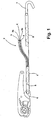
- Fig. 1 serving as a stop or lashing strap tensioning belt 1 forms in the region of its ends for fastening a ratchet 6 and a hook 7 a loop in which its folded one end to form the loop and on the end portion of the tensioning belt. 1 has been laid. So that this loop does not accidentally come loose even under high loads, the tension belt is sewn in this area.
- the corresponding seam 8 is indicated in Fig. 1 by a dashed line.
- an information means 2 is attached to the tension belt 1.
- the information means 2 comprises a band-shaped, woven insert 4, on which an identification means 3a designed as a label is attached.
- the identification means 3a is printed with the product name and with information about the product information required by the relevant standards, such as the maximum load.
- a label identification means 3b On the back of the insert 4 is another formed in the manner of a label identification means 3b attached, which is printed with a quick guide to use the tension belt.
- the insert 4 with the two identification means 3a and 3b attached thereto is surrounded by a protective covering 5 made of durable and UV-resistant plastic, which has a thickness of 0.3 mm. Since the protective sheath 5 is transparent, the identification means 3a and 3b underneath are easy to read.
- the identification means 3a, 3b can be formed by sections of a strip which is directed in the longitudinal direction of the tear-resistant insert 4 directed around the stop means 1 associated end and sewn together with the insert 4 with the stop means 1. The portion of the strip lying loosely on the upper side of the insert 4 in this way then forms the identification means 3a, while the strip portion extending along the back of the insert 4 forms the identification means 3b.
- the information means 2 is connected via the seam 8 with the stop or lashing means 1 only at one end. In this way, the information means 2 can be folded on both sides of the tension belt, so that even when lifting, conveying, securing or attaching differently shaped transport goods, the information means 2 is always easily visible.
- the stop or lashing means 1 described above by way of example and the corresponding information means 2 ensure a readability of the product-specific information even after a long time thanks to the stable and durable multilayer structure of the information medium 2.
- the risk of fatigue breakage caused by fluttering of the information medium 2 in the airstream is significantly reduced by the multi-layered, solid construction.
- the tearing is avoided by the backing of the webbing.
- the identification material was the weak point, since it had to be both easy to print and at the same time be able to bear high mechanical loads.
- the area of the sewing zone at which the identification means in the prior art were sewn to the respective webbing (transport, securing or lifting means) was prone to tearing off due to the perforation associated with sewing.
- this problem no longer exists, since the tear-resistant insert supports the identification means, so that the mechanical loads occurring in practical use no longer affect the material of the identification means as much as in the prior art.
- the information means 10 shown in Fig. 2 has a tear-resistant, band-shaped layer 11, which is made of a technical fabric, as used for example for the production of belts, etc.
- the tear-resistant insert 11 carries on its upper side an identification means 12, which is glued, for example, on the surface of the insert 11.
- the identification means 12 is, for example, a commercially available transponder which can be suitably used is coded so that it allows a unique identification of the equipped with the information means 10 belt, carrying tools, etc. With the help of the identification means 12 can be easily inventory stocks, location and duration and similar relevant for the proper use of inventively characterized goods detect that may be of crucial importance for the safe use of these goods.
- the identification means 12 is coated with a flexible plastic layer 13, which is formed for example by an applied to the tear-resistant layer 11 polyurethane.
- a label-like identification means 14 which covers the top and bottom of the insert.
- the necessary product information is printed.
- the material of the identification means 14 is chosen so that it can be printed well and simply put around the insert 11.
- a transparent, made of PVC hose is drawn, which covers the identification means 14 and with him the tear-resistant insert 11 with the identification means 12 and the plastic layer 13 from all sides.
- the Tear-resistant insert 11 with the identification means 12 and the plastic layer 13, and the identification means 14 surrounding the insert 11 in the longitudinal direction as well as the protective sheath 15 thus form a stack of material layers which together form the information means 10.
- this information means 10 At its end seen in the longitudinal direction of this information means 10 is sewn by means of a seam 16 with the end of a support belt 17.
- the protective sheath 15 protects the identification means 14 and the transponder 12 against external influences.
- the tear-resistant layer ensures that the information means 10 can withstand high mechanical loads and tear-off from the end of the carrying belt 17 is effectively prevented.
Landscapes
- Engineering & Computer Science (AREA)
- Mechanical Engineering (AREA)
- Transportation (AREA)
- Physics & Mathematics (AREA)
- General Physics & Mathematics (AREA)
- Theoretical Computer Science (AREA)
- Purses, Travelling Bags, Baskets, Or Suitcases (AREA)
- Package Frames And Binding Bands (AREA)
- Professional, Industrial, Or Sporting Protective Garments (AREA)
- Polishing Bodies And Polishing Tools (AREA)
- Detergent Compositions (AREA)
- Laminated Bodies (AREA)
Description
- Die Erfindung betrifft ein Mittel zum Anschlagen, Sichern oder Verzurren eines Guts oder zum Sichern einer Person, wie Spanngurt, Tragegurt, Zugband, Seil und Auffanggurte oder desgleichen, mit einem daran befestigten Informationsmittel. Derartige Produkte werden beispielsweise zum Heben, Fördern und Befestigen von Transportgütern sowie zur Absturzsicherung von Personen eingesetzt.
- Darüber hinaus betrifft die Erfindung ein Informationsmittel zur Befestigung an einem Anschlag- oder Verzurrmittel der zuvor genannten Art, welches dazu dient, dem Anwender wichtige produktspezifische Informationen über das zu verwendende Anschlag- oder Verzurrmittel zu geben. Solche Informationen können der Produktname, die maximale Belastbarkeit bzw. Traglast, eine Kurzanleitung etc. sein.
- Die bisher verwendeten Informationsmittel bestehen in der Regel entweder aus einem unmittelbaren Aufdruck der Informationen auf das entsprechende Anschlag- oder Verzurrmittel oder aber aus einem bedruckten Gewebeband, welches seinerseits mit dem entsprechenden Anschlag- oder Verzurrmittel bzw. PSA-Produkt ("PSA" = Personen-Sicherungs-Ausrüstung) verbunden ist. Diese Verbindung kann beispielsweise durch Aufnähen erfolgen.
- Nachteilig am beschriebenen Stand der Technik ist allerdings, dass im Laufe der Zeit durch die hohen Belastungen, insbesondere aufgrund von Reibung oder Dehnung, die auf das Anschlag- oder Verzurrmittel sowie PSA-Produkte einwirken, das Informationsmittel beschädigt werden oder sogar abreißen kann. Ferner führt ein Flattern eines nur einseitig befestigten Informationsmittels im Fahrtwind zu Ermüdungsbrüchen am Befestigungspunkt. Auch kann es im Laufe der Zeit zu einem Abrieb der bedruckten Bereiche kommen, wodurch die Informationen unleserlich oder zumindest schwer erkennbar werden. Dies wirkt sich negativ auf Anwendungsfreundlichkeit und Produktsicherheit aus.
- Zudem dürfen oft sehr hochwertige, teure in Rede stehende Produkte in der Regel nicht mehr benutzt werden, sobald die betreffenden Informationen nicht mehr einwandfrei feststellbar sind. Besonders kritisch wirkt sich dies dann aus, wenn das Informationsmittel in Folge einer äußeren Belastung von dem jeweiligen Anschlag- oder Verzurrmittel bzw. von dem PSA-Produkt im Einsatz abgetrennt wird. Mit dem Verlust des Informationsmittels geht in der Regel der sofortige Verlust der Zulassung einher.
- Aus der deutschen Gebrauchsmusterschrift DE 81 02 337 U1 ist ein Hebeband bekannt, dass ein erstes in eine Bügel- bzw. Gurtbandschlaufennaht eingenähtes Etikett aufweist, das die zum Hebeband gehörige Information trägt. Als Sicherung gegen einen vorzeitigen Verlust der für die Zulassung des Hebebandes benötigten Informationen ist in die betreffende Naht zusätzlich ein zweites Etikett eingenäht, das nur geringfügig über den Stoß des im Bereich der Naht umgeschlagenen Bandes vorspringt. Dieses zweite, wesentlich kürzere Etikett ist mit den für die Zulassung unbedingt erforderlichen Angaben versehen, die zur Verfügung stehen müssen, solange das Band eingesetzt wird. Dadurch, dass das zweite Etikett nur sehr kurz über den Nahtbereich hervorsteht, soll es durch den Wulst gegen eine Beschädigung geschützt sein, der durch das im Nahtbereich umgeschlagene Band gebildet ist. Problematisch an dieser Art des Schutzes ist jedoch, dass die Schutzwirkung des Wulstes nur über eine sehr kurze Länge gegeben und zudem abhängig von der Dicke des Wulstes ist. Sofern die Schutzwirkung überhaupt eintritt, steht daher auf dem Etikett nur eine geringe Fläche zur Verfügung, die in der Praxis nicht ausreicht, um die vorschriftsmäßige Kennzeichnung eines Hebebandes in einer unter Praxisbedingungen lesbaren Form gewährleisten zu können. Hinzu kommt, dass es auch bei diesem Stand der Technik dazu kommen kann, dass erstes und zweites Etikett aufgrund der im praktischen Einsatz dauernd auftretenden Bewegungen im Nahtbereich ermüden und vorzeitig von dem Hebeband abgetrennt werden.
- Neben dem voranstehend erläuterten Stand der Technik ist aus dem deutschen Gebrauchsmuster DE 94 14 241 U1 ein gewebtes Chemiefaserband bekannt, bei dem eine Beschriftung vorgesehen ist. Die Beschriftung wird dabei von einer beschriftungsfreundlichen, bevorzugt aus Kunststoff bestehenden Grundierungsschicht getragen, die dabei unmittelbar auf das Gewebegrundmaterial des Bandes aufgebracht ist. Sie stellt eine sichere Verbindung zwischen dem Gewebegrundmaterial des Bandes und der Beschichtung her. Durch eine auf die Beschriftung aufgebrachte äußere Schutzschicht ist die Beschriftung zudem gegen eine Beschädigung durch von außen wirkende Kräfte geschützt. Eine entsprechende, auf der von der Beschriftung abgewandten Rückseite des Gewebegrundmaterials aufgebrachte zweite Schutzschicht schützt die Beschichtung vor Beschädigungen durch Belastungen, die von der Rückseite her auf das Band wirken.
- Ausgehend vom voranstehend erläuterten Stand der Technik bestand die Aufgabe der Erfindung darin, ein Mittel der Eingangs genannten Art und ein entsprechend geeignetes Informationsmittel zu schaffen, mit dem auch unter harten Einsatzbedingungen gewährleistet ist, dass die vorschriftsmäßige Kennzeichnung über eine lange Zeit erhalten bleibt.
- In Bezug auf das Mittel zum Anschlagen, Sichern oder zum Verzurren eines Guts, wie Spanngurt, Tragegurt, Zugband, Seil, Auffanggurt oder desgleichen, mit einem daran befestigten Informationsmittel ist diese Aufgabe erfindungsgemäß dadurch gelöst worden, dass das Informationsmittel aus mindestens einem Identifikationsmittel, einer Einlage von gegenüber dem Identifikationsmittel erhöhter Reißfestigkeit und einer Schutzumhüllung gebildet ist, die mindestens das Identifikationsmittel umgibt.
- In Bezug auf das Informationsmittel zur Kennzeichnung eines Mittels zum Anschlagen, Sichern oder Verzurren eines Guts oder zum Sichern einer Person, wie Spanngurt, Tragegurt, Zugband, Seil, Auffanggurt oder desgleichen, besteht die erfindungsgemäße Lösung der oben genannten Aufgabe darin, dass es aus mindestens je einem Identifikationsmittel, einer Einlage mit gegenüber dem Identifikationsmittel erhöhter Reißfestigkeit und einer Schutzumhüllung gebildet ist, die mindestens das Identifikationsmittel umgibt, und unabhängig von dem Mittel als Einheit miteinander verbunden ist.
- Das erfindungsgemäße Informationsmittel ist mehrlagig aufgebaut. Jeder der Lage des Informationsmittels ist dabei eine eigene Funktion zugeordnet, so dass die Lagen jeweils aus einem für ihre Funktion optimal geeigneten Material hergestellt sein können. So kann es sich bei dem als Informationsträger vorgesehenen Identifikationsmittel um ein Etikett handeln, das aus einem Material hergestellt ist, welches sich optimal bedrucken lässt und auch nach langem Gebrauch noch eine gute Lesbarkeit gewährleistet. Ebenso kann das Identifikationsmittel so ausgewählt werden, dass es optimal als Träger für eine optisch, elektronisch oder in sonstiger Form maschinenlesbare Information geeignet ist.
- Die Auswahl des jeweiligen Identifikationsmittels kann dabei ohne Rücksicht auf eine bestimmte, zur dauerhaften Befestigung erforderliche Festigkeit erfolgen, da es durch die reißfeste Einlage gegen eine vorzeitige Zerstörung geschützt ist. So lassen sich für das Identifikationsmittel Materialien verwenden, die nur eine geringe Reißfestigkeit aufweisen. Die eine höhere Reißfestigkeit als das Identifikationsmittel aufweisende Einlage stellt auch in diesem Fall sicher, dass das Identifikationsmittel über die gesamte Einsatzdauer des entsprechend gekennzeichneten Hebemittels, Sicherungsmittels, Verzurrmittels oder PSA-Produkts sicher befestigt bleibt.
- Auf der reißfesten Einlage liegt das Identifikationsmittel bei einer von außen wirkenden Belastung auf und wird von ihr gestützt. Die reißfeste Einlage nimmt so die insgesamt auf das Informationsmittel wirkenden Zug- und Biegekräfte auf und verhindert, dass die verschiedenen Lagen des Informationsmittels durch diese Kräfte beschädigt werden.
- Der Schutz des Identifikationsmittels gegen Abrieb oder vergleichbare Einwirkungen von außen stellt schließlich die Umhüllung sicher, die um Identifikationsmittel und die Einlage gelegt ist. Diese Ummantelung schützt das Identifikationsmittel und die Einlage insbesondere gegen Witterungseinflüsse und direkten mechanischen Kontakt mit Fremdteilen. Da auch sie durch die reißfeste Einlage gegen eine Zerstörung bei auf sie wirkenden Zugkräften oder Biegekräften geschützt ist, kann das für die Schutzumhüllung verwendete Material aus einem weichen, witterungsbeständigen und Stöße dämpfenden Material gefertigt sein, ohne selbst eine hohe Reißfestigkeit zu besitzen.
- Durch die erfindungsgemäße Ausgestaltung eines Informationsmittels ist somit sichergestellt, dass die produktspezifischen Informationen auch nach langer Zeit und bei regelmäßiger Anwendung erhalten und zu jederzeit gut lesbar sind. Die Lebenserwartung eines erfindungsgemäßen Informationsmittels ist daher deutlich erhöht. Im Ergebnis stellt die Erfindung sicher, dass ein erfindungsgemäß ausgestattetes Mittel zum Anschlagen, Verzurren und Sichern bis zum Erreichen in vorschriftsmäßiger Weise gekennzeichnet bleibt und die Gefahr eines vorzeitigen Verlustes der Zulassung aufgrund eines Unbrauchbarwerdens seiner Kennzeichnung auf ein Minimum reduziert ist.
- Die Schutzumhüllung kann als Schlauch, Folie oder als Schutzbeschichtung ausgebildet sein und beispielsweise aus einem Kunststoff, insbesondere aus Polyethylen (PE) oder aus Polyvinylchlorid (PVC), bestehen. Dabei ist die Ummantelung bevorzugt durchsichtig, um das Identifikationsmittel ohne großen Umstand lesen zu können. Sie sollte auch UV-beständig sein, damit auch noch bei längerem Gebrauch ihre einwandfreie Funktion gewährleistet bleibt.
- Um eine ausreichende Flexibilität zu gewährleisten, sollte in solchen Fällen, in denen die Ummantelung aus PE- oder PVC-Material gefertigt ist, die Dicke der Ummantelung höchstens einen Millimeter betragen. Als Optimum für die Materialdicke der Ummantelung haben praktische Versuche eine Dicke von 0,3 mm +/- 0,1 mm ergeben.
- Die reißfeste Einlage besteht gemäß einer bevorzugten Ausführungsform aus einer technischen Textilie, insbesondere einem Gewebe, und ist insbesondere bandförmig ausgebildet, um bei vereinfachter Befestigung auch ein längeres Identifikationsmittel problemlos stützen zu können. Die separate Einlage erhöht die Steifigkeit und damit die Stabilität des Informationsmittels, was insbesondere einem Flattern des Informationsmittels im Fahrtwind entgegenwirkt und die Gefahr eines Ermüdungsbruchs des Identifikationsmittels deutlich reduziert.
- Bei Verwendung einer insbesondere bandförmigen, aber auch anders geformten reißfesten Einlage kann auf jeder Seite zumindest ein Identifikationsmittel vorgesehen sein. So kann beispielsweise auf der Vorderseite der Einlage ein Etikett mit der Produktbezeichnung und den seitens der betreffenden Normen geforderten Produktinformationen, wie der maximalen Traglast, und auf der Rückseite ein Etikett mit einer Kurzanleitung zur Verwendung des Produkts befestigt sein. Ebenso ist es denkbar, auf der einen Seite der Einlage ein maschinenlesbares Identifikationsmittel anzuordnen, während auf der anderen Seite der Einlage ein Etikett als Identifikationsmittel vorgesehen ist, auf dem die erforderlichen Informationen im Klartext angegeben sind.
- Das Etikett kann mit der Einlage vernäht, verklebt und/oder vernietet sein. Ebenso ist es denkbar, beidseitig der Einlage Abschnitte des Identifikationsmittels dadurch zu positionieren, dass bei einem band- oder streifenförmig ausgebildeten Identifikationsmittel ein mit den erforderlichen Informationen versehener Streifenabschnitt des Identifikationsmittels um die reißfeste Einlage gelegt wird, so dass der eine Streifenabschnitt sich in Richtung der Einlage auf der Vorderseite und der andere Etikettstreifenabschnitt sich auf der anderen Seite der reißfesten Einlage erstreckt.
- Insbesondere dann, wenn das Anschlag-, Verzurrmittel oder das PSA-Produkt zumindest abschnittsweise aus einem textilen Werkstoff besteht, beispielsweise gewebt ist, kann das Informationsmittel auf einfache Weise durch Annähen auf ihm befestigt werden. Ein Annähen ist aber auch möglich, wenn das Anschlag- oder Verzurrmittel aus einem anderen Material besteht. Selbstverständlich ist es auch denkbar, dass das Informationsmittel mit dem Anschlag- oder Verzurrmittel verklebt und/oder vernietet ist. Dabei kann auch nur ein Ende des Informationsmittels mit dem Anschlag- oder Verzurrmittel verbunden sein. Letztlich kommt es nur darauf an, dass diese Verbindung auch hohen Belastungen standhält.
- Wird ein maschinenlesbares Identifikationsmittel eingesetzt, so kann beispielsweise eine vereinfachte Materialverwaltung dadurch ermöglicht werden, dass der Standort des entsprechend gekennzeichneten Trag-, Sicherungs- oder Verzurrmittels mittels geeigneter Detektoren in einem Lager erfasst wird. Des Weiteren können mit Hilfe des Identifikationsmittels die Materialaus- und Materialrückgabe auf einfache Weise organisiert werden. Darüber hinaus können die gesetzlich vorgeschriebenen Angaben bei einer Kontrolle direkt in ein Datenverarbeitungssystem eingelesen und mit dort vorhandenen Solldaten abgeglichen werden.
- Kostengünstig lässt sich ein maschinenlesbares Identifikationsmittel dadurch verwirklichen, dass es ein Transponder ist. Ebenso ist es jedoch auch denkbar, einen optisch abtastbaren Barcode oder andere maschinenlesbare Informationen auf das Identifikationsmittel aufzubringen.
- Abhängig von der Art des jeweils eingesetzten Identifikationsmittels kann es zweckmäßig sein, dieses Identifikationsmittel direkt auf der Einlage zu befestigen. Auf diese Weise stellt die Einlage mit ihrer erhöhten Reißfestigkeit auch bei Identifikationsmitteln, die empfindlich gegen Zug- oder Druckbelastungen sind, sicher, dass seine dauerhafte Funktion gewährleistet ist. Zu diesem Zweck kann das Identifikationsmittel mit der Einlage fest verbunden, insbesondere vernäht, vernietet und/oder verklebt werden.
- Insbesondere dann, wenn das Identifikationsmittel von der reißfesteren Einlage getragen wird oder als Etikett ausgebildet ist, kann es ausreichend sein, wenn nur ein Abschnitt des Informationsmittels mit dem Anschlag- oder Verzurrmittel direkt verbunden ist. Dies ist beispielsweise dann gegeben, wenn als Identifikationsmittel ein längliches Etikett eingesetzt wird, dass nur an einer Schmalseite mit dem jeweiligen Hebe-, Verzurr- oder Sicherungsmittel verbunden wird.
- Das Identifikationsmittel kann mit einer Schutzschicht überzogen sein, um einer Beschädigung durch äußere Einflüsse vorzubeugen. Dabei kann die Schutzschicht durch einen flexiblen Kunststoff, zum Beispiel ein Silikon oder ein Polyurethan, gebildet sein, die den Bewegungen des Informationsmittels folgen kann.
- Nachfolgend wird die Erfindung anhand einer ein Ausführungsbeispiel darstellenden Zeichnung näher erläutert. Es zeigen schematisch:
- Fig. 1
- einen Endabschnitt eines Spanngurts in seitlicher Ansicht,
- Fig. 2
- ein Informationsmittel in seitlicher Ansicht.
- Der in Fig. 1 dargestellte, als Anschlag- oder Verzurrmittel dienende Spanngurt 1 bildet im Bereich seiner Enden zur Befestigung einer Ratsche 6 bzw. eines Hakens 7 eine Schlaufe, in dem sein eines Ende unter Ausbildung der Schlaufe umgelegt und auf den Endabschnitt des Spanngurts 1 gelegt worden ist. Damit sich diese Schlaufe auch bei hohen Belastungen nicht ungewollt löst, ist der Spanngurt in diesem Bereich vernäht. Die entsprechende Naht 8 ist in Fig. 1 durch eine gestrichelte Linie angedeutet.
- Mittels derselben Naht 8 ist an dem Spanngurt 1 auch ein Informationsmittel 2 befestigt. Das Informationsmittel 2 umfasst eine bandförmige, gewebte Einlage 4, auf deren ein als Etikett ausgebildetes Identifikationsmittel 3a befestigt ist. Das Identifikationsmittel 3a ist mit der Produktbezeichnung und mit Informationen über die seitens der betreffenden Normen geforderten Produktinformationen, wie die maximale Traglast, bedruckt.
- Auf der Rückseite der Einlage 4 ist ein weiteres nach Art eines Etiketts ausgebildetes Identifikationsmittel 3b befestigt, welches mit einer Kurzanleitung zur Verwendung des Spanngurtes bedruckt ist. Die Einlage 4 mit den beiden darauf befestigten Identifikationsmitteln 3a und 3b ist von einer Schutzumhüllung 5 aus strapazierfähigem und UVbeständigem Kunststoff umgeben, die eine Stärke von 0,3 mm aufweist. Da die Schutzumhüllung 5 durchsichtig ist, sind die darunter befindlichen Identifikationsmittel 3a und 3b gut lesbar.
- Die Identifikationsmittel 3a,3b können dabei durch Abschnitte eines Streifens gebildet sein, der in Längsrichtung der reißfesten Einlage 4 gerichtet um deren dem Anschlagmittel 1 zugeordnetes Ende gelegt und dort gemeinsam mit der Einlage 4 mit dem Anschlagmittel 1 vernäht ist. Der auf diese Weise lose auf der Oberseite der Einlage 4 liegende Abschnitt des Streifens bildet dann das Identifikationsmittel 3a, während der entlang der Rückseite der Einlage 4 sich erstreckende Streifenabschnitt das Identifikationsmittel 3b bildet.
- Das Informationsmittel 2 ist über die Naht 8 mit dem Anschlag- oder Verzurrmittel 1 lediglich an einem Ende verbunden. Auf diese Weise kann das Informationsmittel 2 zu beiden Seiten an den Spanngurt geklappt werden, so dass auch beim Heben, Fördern, Sichern oder Befestigen unterschiedlich geformter Transportgüter das Informationsmittel 2 immer gut sichtbar zugänglich ist.
- Das zuvor beispielhaft beschriebene Anschlag- oder Verzurrmittel 1 und das entsprechende Informationsmittel 2 gewährleisten durch den stabilen und strapazierfähigen mehrlagigen Aufbau des Informationsmittels 2 auch nach langer Zeit noch eine gute Lesbarkeit der produktspezifischen Informationen. Außerdem wird durch den mehrschichtigen, soliden Aufbau auch die Gefahr eines Ermüdungsbruches durch Flattern des Informationsmittels 2 im Fahrtwind deutlich herabgesetzt. Insbesondere das Herausreißen wird durch die Unterlegung des Gurtbandes vermieden. Bislang war das Identifikationsmittelmaterial die Schwachstelle, da es einerseits gut bedruckbar und gleichzeitig in der Lage sein musste, hohe mechanische Belastungen zu ertragen. Insbesondere der Bereich der Einnähzone, an der das Identifikationsmittel beim Stand der Technik an das jeweilige Gurtband (Transport-, Sicherungs- oder Hebemittel) vernäht worden ist, war aufgrund der mit dem Vernähen einhergehenden Perforierung für ein Abreißen anfällig. Bei der Erfindung besteht dieses Problem nicht mehr, da die reißfeste Einlage das Identifikationsmittel stützt, so dass die im praktischen Einsatz auftretenden mechanischen Belastungen sich nicht mehr so stark auf das Material des Identifikationsmittels auswirken wie beim Stand der Technik.
- Das in Fig. 2 dargestellte Informationsmittel 10 weist eine reißfeste, bandförmige Lage 11 auf, die aus einem technischen Gewebe gefertigt ist, wie es beispielsweise zur Herstellung von Gurten etc. eingesetzt wird. Die reißfeste Einlage 11 trägt auf ihrer Oberseite ein Identifikationsmittel 12, das beispielsweise auf die Oberfläche der Einlage 11 aufgeklebt ist. Bei dem Identifikationsmittel 12 handelt es sich beispielsweise um einen handelsüblichen Transponder, der in geeigneter Weise so codiert ist, dass er eine eindeutige Identifikation des mit dem Informationsmittel 10 ausgestatteten Gurts, Tragezeuge etc. erlaubt. Mit Hilfe des Identifikationsmittels 12 lassen sich auf einfache Weise Lagerbestände, Einsatzort und -dauer und ähnliche für die ordnungsgemäße Verwendung von erfindungsgemäß gekennzeichneten Gütern relevanten erfassen, die von entscheidender Bedeutung für die sichere Verwendung dieser Güter sein können.
- Zum Schutz gegen Beschädigungen durch von außen wirkende Belastungen ist das Identifikationsmittel 12 mit einer flexiblen Kunststoffschicht 13 überzogen, die beispielsweise durch ein auf die reißfeste Lage 11 aufgetragenes Polyurethan gebildet ist.
- Um die reißfeste Einlage 11 mit dem Identifikationsmittel 12 und der Kunststoffschicht 13 ist in Längsrichtung der Einlage 11 ein wiederum etikettartiges Identifikationsmittel 14 gelegt, das die Ober- und Unterseite der Einlage abdeckt. Auf der jeweils außen liegenden Oberfläche des Identifikationsmittels 14 sind die notwendigen Produktinformationen ausgedruckt. Das Material des Identifikationsmittels 14 ist dabei so gewählt, dass es sich gut bedrucken und einfach um die Einlage 11 herumlegen lässt.
- Über das Identifikationsmittel 14 ist als Schutzumhüllung 15 ein durchsichtiger, aus PVC gefertigter Schlauch gezogen, der das Identifikationsmittel 14 und mit ihm die reißfeste Einlage 11 mit dem Identifikationsmittel 12 und der Kunststoffschicht 13 von allen Seiten her abdeckt. Die reißfeste Einlage 11 mit dem Identifikationsmittel 12 und der Kunststoffschicht 13, und das die Einlage 11 in Längsrichtung gesehen umgebende Identifikationsmittel 14 sowie die Schutzumhüllung 15 bilden so einen Stapel von Materiallagen, die gemeinsam das Informationsmittel 10 bilden.
- An seinem in Längsrichtung gesehenen einen Ende ist dieses Informationsmittel 10 mittels einer Naht 16 mit dem Ende eines Traggurtes 17 vernäht. Im praktischen Einsatz schützt die Schutzumhüllung 15 das Identifikationsmittel 14 und den Transponder 12 gegen äußere Einflüsse. Gleichzeitig stellt die reißfeste Lage sicher, dass das Informationsmittel 10 auch hohen mechanischen Belastungen standhalten und ein Abreißen vom Ende des Traggurtes 17 wirksam verhindert wird.
-
- 1
- Anschlag- oder Verzurrmittel
- 2
- Informationsmittel
- 3a
- Identifikationsmittel
- 3b
- Identifikationsmittel
- 4
- Einlage
- 5
- Schutzumhüllung
- 6
- Ratsche
- 7
- Haken
- 8
- Naht
- 10
- Informationsmittel
- 11
- reißfeste, bandförmige Einlage
- 12
- Identifikationsmittel
- 13
- Kunststoffschicht
- 14
- Identifikationsmittel
- 15
- Schutzumhüllung
- 16
- Naht
- 17
- Traggurt
Claims (23)
- Mittel (1) zum Anschlagen, Sichern oder Verzurren eines Guts oder zum Sichern einer Person, wie Spanngurt, Tragegurt, Zugband, Seil, Auffanggurt oder desgleichen, mit einem daran befestigten Informationsmittel (2), dadurch gekennzeichnet, dass das Informationsmittel (2) aus mindestens einem Identifikationsmittel (3a, 3b), einer Einlage (4) von gegenüber dem Identifikationsmittel (3a, 3b) erhöhter Reißfestigkeit und einer Schutzumhüllung (5) gebildet ist, die mindestens das Identifikationsmittel (3a, 3b) umgibt.
- Mittel nach Anspruch 1, dadurch gekennzeichnet, dass es fest mit dem Informationsmittel (2) verbunden ist.
- Mittel nach Anspruch 2, dadurch gekennzeichnet, dass es mit dem Informationsmittel (2) vernäht ist.
- Mittel nach einem der Ansprüche 1 oder 2, dadurch gekennzeichnet, dass es mit dem Informationsmittel (2) verklebt und/oder vernietet ist.
- Mittel nach einem der Ansprüche 1 oder 2, dadurch gekennzeichnet, dass das Identifikationsmittel (3a, 3b) lesbar ist.
- Mittel nach Anspruch 5, dadurch gekennzeichnet, dass das Identifikationsmittel (2) maschinenlesbar ist.
- Mittel nach einem der voranstehenden Ansprüche, dadurch gekennzeichnet, dass die Einlage (4) aus einer technischen Textilie, insbesondere einem Gewebe, besteht.
- Mittel nach einem der voranstehenden Ansprüche, dadurch gekennzeichnet, dass die Einlage (4) bandförmig ausgebildet ist.
- Mittel nach einem der voranstehenden Ansprüche, dadurch gekennzeichnet, dass die Einlage (4) beidseitig als Träger von Identifikationsmitteln (3a, 3b) dient.
- Mittel nach einem der voranstehenden Ansprüche, dadurch gekennzeichnet, dass das Identifikationsmittel (3a, 3b) mit der Einlage (4) fest verbunden, insbesondere vernäht und/oder vernietet und/oder verklebt ist.
- Mittel nach einem der voranstehenden Ansprüche, dadurch gekennzeichnet, dass nur ein Abschnitt des Informationsmittels (2) mit dem Anschlag- oder Verzurrmittel direkt verbunden ist.
- Mittel nach einem der voranstehenden Ansprüche, dadurch gekennzeichnet, dass die Schutzumhüllung (5) ein Schlauch oder eine Folie ist.
- Mittel nach einem der voranstehenden Ansprüche, dadurch gekennzeichnet, dass die Schutzumhüllung (5) aus Kunststoff, insbesondere aus Polyethylen (PE) oder aus Polyvinylchlorid (PVC), besteht.
- Mittel nach einem der voranstehenden Ansprüche, dadurch gekennzeichnet, dass die Schutzumhüllung (5) durchsichtig ist.
- Mittel nach einem der voranstehenden Ansprüche, dadurch gekennzeichnet, dass das Identifikationsmittel (3a, 3b) ein mit Informationen versehenes Etikett ist.
- Mittel nach einem der voranstehenden Ansprüche, dadurch gekennzeichnet, dass das Identifikationsmittel (3a,3b) ein Transponder ist.
- Mittel nach einem der voranstehenden Ansprüche, dadurch gekennzeichnet, dass das Identifikationsmittel (3a, 3b) von der Einlage getragen wird.
- Mittel nach einem der voranstehenden Ansprüche, dadurch gekennzeichnet, dass die Schutzumhüllung als Schutzschicht ausgebildet ist, mit der das Identifikationsmittel (3a, 3b) überzogen ist.
- Mittel nach Anspruch 18, dadurch gekennzeichnet, dass die Schutzschicht ein flexibler Kunststoff ist.
- Mittel nach Anspruch 19, dadurch gekennzeichnet, dass der flexible Kunststoff ein Silikon oder Polyurethan ist.
- Mittel nach einem der voranstehenden Ansprüche, dadurch gekennzeichnet, dass alle Lagen des Informationsmittels durch die Schutzumhüllung (5) umgeben sind.
- Mittel nach einem der voranstehenden Ansprüche, dadurch gekennzeichnet, dass die Schutzumhüllung aus einem UV-beständigen Material besteht.
- Informationsmittel (2) zur Kennzeichnung eines Mittels (1) zum Anschlagen, Sichern oder Verzurren eines Guts, wie Spanngurt, Tragegurt, Zugband, Seil, Auffanggurt oder desgleichen, dadurch gekennzeichnet, dass es aus mindestens je einem Identifikationsmittel (3a, 3b), einer Einlage mit gegenüber dem Identifikationsmittel (3a, 3b) erhöhter Reißfestigkeit und einer Schutzumhüllung (5), die mindestens das Identifikationsmittel (3a, 3b) umgibt, besteht und unabhängig von dem Mittel (1) zum Anschlagen, Sichern oder Verzurren eines Guts als Einheit miteinander verbunden ist.
Applications Claiming Priority (3)
| Application Number | Priority Date | Filing Date | Title |
|---|---|---|---|
| DE102004001265 | 2004-01-08 | ||
| DE102004001265A DE102004001265B4 (de) | 2004-01-08 | 2004-01-08 | Mittel zum Anschlagen oder zum Verzurren eines Guts |
| PCT/EP2005/000104 WO2005066061A1 (de) | 2004-01-08 | 2005-01-07 | Mittel zum anschlagen oder zum verzurren eines guts und informationsmittel |
Publications (2)
| Publication Number | Publication Date |
|---|---|
| EP1590291A1 EP1590291A1 (de) | 2005-11-02 |
| EP1590291B1 true EP1590291B1 (de) | 2006-10-04 |
Family
ID=34744633
Family Applications (1)
| Application Number | Title | Priority Date | Filing Date |
|---|---|---|---|
| EP05700755A Expired - Lifetime EP1590291B1 (de) | 2004-01-08 | 2005-01-07 | Mittel zum anschlagen oder zum verzurren eines guts und informationsmittel |
Country Status (7)
| Country | Link |
|---|---|
| US (1) | US9511980B2 (de) |
| EP (1) | EP1590291B1 (de) |
| AT (1) | ATE341520T1 (de) |
| AU (1) | AU2005203946B2 (de) |
| DE (2) | DE102004001265B4 (de) |
| ES (1) | ES2274509T3 (de) |
| WO (1) | WO2005066061A1 (de) |
Families Citing this family (5)
| Publication number | Priority date | Publication date | Assignee | Title |
|---|---|---|---|---|
| DE102007051675B4 (de) * | 2007-10-26 | 2011-11-24 | Hoffmann Air Cargo Equipment Gmbh | Verfahren zur Herstellung von Nahtverbindungen an Gurtbändern für technische Zwecke |
| DE102011012393A1 (de) * | 2011-02-25 | 2012-08-30 | Carl Stahl Gmbh | Zug- oder Spannmittel, insbesondere Zurrgurt |
| US10577230B1 (en) | 2018-10-22 | 2020-03-03 | Gary Shelton | Winch device |
| CN112279071B (zh) * | 2019-07-25 | 2023-02-28 | 晋江市美田制冷设备有限公司 | 一种壳管蒸发器吊装用辅助结构 |
| CN117836482A (zh) * | 2021-07-16 | 2024-04-05 | 慕特普伦斯美国股份有限公司 | 反光捆绑条带 |
Family Cites Families (11)
| Publication number | Priority date | Publication date | Assignee | Title |
|---|---|---|---|---|
| DE8102337U1 (de) * | 1981-01-30 | 1981-07-09 | Franz Dolezych & Co, 4600 Dortmund | Hebeband |
| US4773175A (en) * | 1984-07-16 | 1988-09-27 | Larsen Clifford A | Display board for a shopping cart |
| DE8708432U1 (de) * | 1987-06-15 | 1987-08-06 | Dolezych, Udo, 5804 Herdecke | Band zum Umschlingen und Heben einer Last |
| DE3904325C2 (de) * | 1988-11-25 | 1997-08-07 | Dolezych Udo Dipl Kaufm | Kennzeichnungsträger zur Kennzeichnung von zum Bewegen von Lasten vorgesehenen Chemiefaser-Flachgewebe-Hebebändern und/oder -schlingen |
| DE9111547U1 (de) * | 1991-09-17 | 1991-12-19 | Spanset Inter Ag, Oetwil Am See | Hebeband mit aufgenähtem reflektierendem Etikett |
| WO1995002877A1 (en) * | 1993-07-15 | 1995-01-26 | Precision Dynamics Corporation | Improved pocket-style identification bracelet |
| DE9414241U1 (de) * | 1994-09-02 | 1995-02-23 | Dolezych, Udo, Dipl.-Kaufm., 44147 Dortmund | Gewebtes Chemiefaserband |
| US6105295A (en) * | 1998-05-11 | 2000-08-22 | Fast Industries, Ltd. | Label holder for attachment to different shelf channels |
| US6632042B1 (en) * | 2000-07-11 | 2003-10-14 | Avery Dennison Corporation | Printed sheet protector system and method |
| US6644694B2 (en) * | 2001-07-06 | 2003-11-11 | Phillip Seawright | Wearable folded map |
| US6971201B2 (en) * | 2003-06-10 | 2005-12-06 | Southern Imperial, Inc. | Curved back label holder for a shelf |
-
2004
- 2004-01-08 DE DE102004001265A patent/DE102004001265B4/de not_active Expired - Fee Related
-
2005
- 2005-01-07 US US10/551,871 patent/US9511980B2/en not_active Expired - Fee Related
- 2005-01-07 DE DE502005000126T patent/DE502005000126D1/de not_active Expired - Lifetime
- 2005-01-07 AU AU2005203946A patent/AU2005203946B2/en not_active Ceased
- 2005-01-07 WO PCT/EP2005/000104 patent/WO2005066061A1/de not_active Ceased
- 2005-01-07 ES ES05700755T patent/ES2274509T3/es not_active Expired - Lifetime
- 2005-01-07 EP EP05700755A patent/EP1590291B1/de not_active Expired - Lifetime
- 2005-01-07 AT AT05700755T patent/ATE341520T1/de active
Also Published As
| Publication number | Publication date |
|---|---|
| US9511980B2 (en) | 2016-12-06 |
| AU2005203946B2 (en) | 2010-04-08 |
| ES2274509T3 (es) | 2007-05-16 |
| WO2005066061A1 (de) | 2005-07-21 |
| DE502005000126D1 (de) | 2006-11-16 |
| EP1590291A1 (de) | 2005-11-02 |
| DE102004001265A1 (de) | 2005-08-25 |
| US20070068123A1 (en) | 2007-03-29 |
| DE102004001265B4 (de) | 2007-05-31 |
| ATE341520T1 (de) | 2006-10-15 |
| AU2005203946A1 (en) | 2005-07-21 |
Similar Documents
| Publication | Publication Date | Title |
|---|---|---|
| DE3636977A1 (de) | Gepaeckanhaenger | |
| DE102014114341A1 (de) | Etikett | |
| EP2109088B1 (de) | Kennzeichnungsband | |
| EP1634844A1 (de) | Gurtbandvorrichtung | |
| CH647610A5 (de) | Gepaeckanhaenger, insbesondere fuer die kennzeichnung von luftgepaeckstuecken. | |
| DE102004001265B4 (de) | Mittel zum Anschlagen oder zum Verzurren eines Guts | |
| DE102004045905C5 (de) | Schutzelement für textile Zurr- oder Anschlagmittel | |
| DE202004000128U1 (de) | Mittel zum Anschlagen oder zum Verzurren eines Guts und Informationsmittel | |
| EP1018702B1 (de) | Verbundmaterialeinheiten mit transponder | |
| DE102011012393A1 (de) | Zug- oder Spannmittel, insbesondere Zurrgurt | |
| EP2704128B1 (de) | Siegel | |
| DE202005020732U1 (de) | Zurrgurt | |
| DE102005041523B4 (de) | Fördervorrichtung | |
| DE202016004776U1 (de) | Wickelhülse zur Kennzeichnung von rohrförmigen Bauteilen | |
| DE102021112987B4 (de) | Umleitplanken-Baumstammschutzvorrichtung zum Schutz eines Baustammes und/oder eines Astes vor äußeren mechanischen Einflüssen | |
| DE202015102467U1 (de) | Antirutschvorrichtung zum Anbringen an Schulterriemen | |
| WO2010049174A2 (de) | Streifengepäckanhänger | |
| DE202011004292U1 (de) | Kennzeichnungseinrichtung und Kennzeichnungseinheit | |
| DE202010006571U1 (de) | Zurr- und/oder Anschlagmittel | |
| DE9412748U1 (de) | Gewebtes Chemiefaserband | |
| DE102009039380A1 (de) | Fahrzeuginsassen-Rettungsmittel | |
| DE29802034U1 (de) | Datenträger für ein Transport- und Lagermittel | |
| DE202022104232U1 (de) | Vorrichtung zur Präsentation von bandförmigen Gegenständen | |
| DE9303397U1 (de) | Namensanhänger für Gepäckstücke | |
| DE10157638A1 (de) | Eindeutige Kennzeichnung von Mitteln zum Anschlagen oder Verzurren eines Guts |
Legal Events
| Date | Code | Title | Description |
|---|---|---|---|
| PUAI | Public reference made under article 153(3) epc to a published international application that has entered the european phase |
Free format text: ORIGINAL CODE: 0009012 |
|
| 17P | Request for examination filed |
Effective date: 20050730 |
|
| AK | Designated contracting states |
Kind code of ref document: A1 Designated state(s): AT BE BG CH CY CZ DE DK EE ES FI FR GB GR HU IE IS IT LI LT LU MC NL PL PT RO SE SI SK TR |
|
| AX | Request for extension of the european patent |
Extension state: AL BA HR LV MK YU |
|
| GRAP | Despatch of communication of intention to grant a patent |
Free format text: ORIGINAL CODE: EPIDOSNIGR1 |
|
| GRAS | Grant fee paid |
Free format text: ORIGINAL CODE: EPIDOSNIGR3 |
|
| GRAA | (expected) grant |
Free format text: ORIGINAL CODE: 0009210 |
|
| DAX | Request for extension of the european patent (deleted) | ||
| AK | Designated contracting states |
Kind code of ref document: B1 Designated state(s): AT BE BG CH CY CZ DE DK EE ES FI FR GB GR HU IE IS IT LI LT LU MC NL PL PT RO SE SI SK TR |
|
| PG25 | Lapsed in a contracting state [announced via postgrant information from national office to epo] |
Ref country code: CZ Free format text: LAPSE BECAUSE OF FAILURE TO SUBMIT A TRANSLATION OF THE DESCRIPTION OR TO PAY THE FEE WITHIN THE PRESCRIBED TIME-LIMIT Effective date: 20061004 Ref country code: SK Free format text: LAPSE BECAUSE OF FAILURE TO SUBMIT A TRANSLATION OF THE DESCRIPTION OR TO PAY THE FEE WITHIN THE PRESCRIBED TIME-LIMIT Effective date: 20061004 Ref country code: SI Free format text: LAPSE BECAUSE OF FAILURE TO SUBMIT A TRANSLATION OF THE DESCRIPTION OR TO PAY THE FEE WITHIN THE PRESCRIBED TIME-LIMIT Effective date: 20061004 Ref country code: RO Free format text: LAPSE BECAUSE OF FAILURE TO SUBMIT A TRANSLATION OF THE DESCRIPTION OR TO PAY THE FEE WITHIN THE PRESCRIBED TIME-LIMIT Effective date: 20061004 Ref country code: PL Free format text: LAPSE BECAUSE OF FAILURE TO SUBMIT A TRANSLATION OF THE DESCRIPTION OR TO PAY THE FEE WITHIN THE PRESCRIBED TIME-LIMIT Effective date: 20061004 Ref country code: FI Free format text: LAPSE BECAUSE OF FAILURE TO SUBMIT A TRANSLATION OF THE DESCRIPTION OR TO PAY THE FEE WITHIN THE PRESCRIBED TIME-LIMIT Effective date: 20061004 Ref country code: IE Free format text: LAPSE BECAUSE OF FAILURE TO SUBMIT A TRANSLATION OF THE DESCRIPTION OR TO PAY THE FEE WITHIN THE PRESCRIBED TIME-LIMIT Effective date: 20061004 Ref country code: LT Free format text: LAPSE BECAUSE OF FAILURE TO SUBMIT A TRANSLATION OF THE DESCRIPTION OR TO PAY THE FEE WITHIN THE PRESCRIBED TIME-LIMIT Effective date: 20061004 |
|
| REG | Reference to a national code |
Ref country code: GB Ref legal event code: FG4D Free format text: NOT ENGLISH |
|
| REG | Reference to a national code |
Ref country code: CH Ref legal event code: EP |
|
| REG | Reference to a national code |
Ref country code: IE Ref legal event code: FG4D Free format text: LANGUAGE OF EP DOCUMENT: GERMAN |
|
| REF | Corresponds to: |
Ref document number: 502005000126 Country of ref document: DE Date of ref document: 20061116 Kind code of ref document: P |
|
| REG | Reference to a national code |
Ref country code: DE Ref legal event code: R096 Ref document number: 502005000126 Country of ref document: DE Effective date: 20061116 |
|
| GBT | Gb: translation of ep patent filed (gb section 77(6)(a)/1977) |
Effective date: 20061115 |
|
| PG25 | Lapsed in a contracting state [announced via postgrant information from national office to epo] |
Ref country code: SE Free format text: LAPSE BECAUSE OF FAILURE TO SUBMIT A TRANSLATION OF THE DESCRIPTION OR TO PAY THE FEE WITHIN THE PRESCRIBED TIME-LIMIT Effective date: 20070104 Ref country code: DK Free format text: LAPSE BECAUSE OF FAILURE TO SUBMIT A TRANSLATION OF THE DESCRIPTION OR TO PAY THE FEE WITHIN THE PRESCRIBED TIME-LIMIT Effective date: 20070104 Ref country code: BG Free format text: LAPSE BECAUSE OF FAILURE TO SUBMIT A TRANSLATION OF THE DESCRIPTION OR TO PAY THE FEE WITHIN THE PRESCRIBED TIME-LIMIT Effective date: 20070104 |
|
| PG25 | Lapsed in a contracting state [announced via postgrant information from national office to epo] |
Ref country code: MC Free format text: LAPSE BECAUSE OF NON-PAYMENT OF DUE FEES Effective date: 20070131 |
|
| PG25 | Lapsed in a contracting state [announced via postgrant information from national office to epo] |
Ref country code: IS Free format text: LAPSE BECAUSE OF FAILURE TO SUBMIT A TRANSLATION OF THE DESCRIPTION OR TO PAY THE FEE WITHIN THE PRESCRIBED TIME-LIMIT Effective date: 20070204 |
|
| PG25 | Lapsed in a contracting state [announced via postgrant information from national office to epo] |
Ref country code: PT Free format text: LAPSE BECAUSE OF FAILURE TO SUBMIT A TRANSLATION OF THE DESCRIPTION OR TO PAY THE FEE WITHIN THE PRESCRIBED TIME-LIMIT Effective date: 20070316 |
|
| REG | Reference to a national code |
Ref country code: IE Ref legal event code: FD4D Ref country code: ES Ref legal event code: FG2A Ref document number: 2274509 Country of ref document: ES Kind code of ref document: T3 |
|
| ET | Fr: translation filed | ||
| PLBE | No opposition filed within time limit |
Free format text: ORIGINAL CODE: 0009261 |
|
| STAA | Information on the status of an ep patent application or granted ep patent |
Free format text: STATUS: NO OPPOSITION FILED WITHIN TIME LIMIT |
|
| 26N | No opposition filed |
Effective date: 20070705 |
|
| REG | Reference to a national code |
Ref country code: DE Ref legal event code: R097 Ref document number: 502005000126 Country of ref document: DE Effective date: 20070705 |
|
| BERE | Be: lapsed |
Owner name: SPANSET INTER A.G. Effective date: 20070131 |
|
| PG25 | Lapsed in a contracting state [announced via postgrant information from national office to epo] |
Ref country code: BE Free format text: LAPSE BECAUSE OF NON-PAYMENT OF DUE FEES Effective date: 20070131 |
|
| PG25 | Lapsed in a contracting state [announced via postgrant information from national office to epo] |
Ref country code: GR Free format text: LAPSE BECAUSE OF FAILURE TO SUBMIT A TRANSLATION OF THE DESCRIPTION OR TO PAY THE FEE WITHIN THE PRESCRIBED TIME-LIMIT Effective date: 20070105 |
|
| PG25 | Lapsed in a contracting state [announced via postgrant information from national office to epo] |
Ref country code: EE Free format text: LAPSE BECAUSE OF FAILURE TO SUBMIT A TRANSLATION OF THE DESCRIPTION OR TO PAY THE FEE WITHIN THE PRESCRIBED TIME-LIMIT Effective date: 20061004 |
|
| PG25 | Lapsed in a contracting state [announced via postgrant information from national office to epo] |
Ref country code: LU Free format text: LAPSE BECAUSE OF NON-PAYMENT OF DUE FEES Effective date: 20070107 Ref country code: CY Free format text: LAPSE BECAUSE OF FAILURE TO SUBMIT A TRANSLATION OF THE DESCRIPTION OR TO PAY THE FEE WITHIN THE PRESCRIBED TIME-LIMIT Effective date: 20061004 |
|
| PG25 | Lapsed in a contracting state [announced via postgrant information from national office to epo] |
Ref country code: TR Free format text: LAPSE BECAUSE OF FAILURE TO SUBMIT A TRANSLATION OF THE DESCRIPTION OR TO PAY THE FEE WITHIN THE PRESCRIBED TIME-LIMIT Effective date: 20061004 Ref country code: HU Free format text: LAPSE BECAUSE OF FAILURE TO SUBMIT A TRANSLATION OF THE DESCRIPTION OR TO PAY THE FEE WITHIN THE PRESCRIBED TIME-LIMIT Effective date: 20070405 |
|
| REG | Reference to a national code |
Ref country code: FR Ref legal event code: PLFP Year of fee payment: 12 |
|
| REG | Reference to a national code |
Ref country code: FR Ref legal event code: PLFP Year of fee payment: 13 |
|
| REG | Reference to a national code |
Ref country code: FR Ref legal event code: PLFP Year of fee payment: 14 |
|
| PGFP | Annual fee paid to national office [announced via postgrant information from national office to epo] |
Ref country code: FR Payment date: 20230125 Year of fee payment: 19 Ref country code: ES Payment date: 20230224 Year of fee payment: 19 Ref country code: AT Payment date: 20230125 Year of fee payment: 19 |
|
| PGFP | Annual fee paid to national office [announced via postgrant information from national office to epo] |
Ref country code: GB Payment date: 20230124 Year of fee payment: 19 |
|
| P01 | Opt-out of the competence of the unified patent court (upc) registered |
Effective date: 20230515 |
|
| PGFP | Annual fee paid to national office [announced via postgrant information from national office to epo] |
Ref country code: NL Payment date: 20230124 Year of fee payment: 19 |
|
| PGFP | Annual fee paid to national office [announced via postgrant information from national office to epo] |
Ref country code: DE Payment date: 20240123 Year of fee payment: 20 Ref country code: CH Payment date: 20240202 Year of fee payment: 20 |
|
| PGFP | Annual fee paid to national office [announced via postgrant information from national office to epo] |
Ref country code: IT Payment date: 20240124 Year of fee payment: 20 |
|
| REG | Reference to a national code |
Ref country code: NL Ref legal event code: MM Effective date: 20240201 |
|
| REG | Reference to a national code |
Ref country code: AT Ref legal event code: MM01 Ref document number: 341520 Country of ref document: AT Kind code of ref document: T Effective date: 20240107 |
|
| GBPC | Gb: european patent ceased through non-payment of renewal fee |
Effective date: 20240107 |
|
| PG25 | Lapsed in a contracting state [announced via postgrant information from national office to epo] |
Ref country code: GB Free format text: LAPSE BECAUSE OF NON-PAYMENT OF DUE FEES Effective date: 20240107 |
|
| PG25 | Lapsed in a contracting state [announced via postgrant information from national office to epo] |
Ref country code: FR Free format text: LAPSE BECAUSE OF NON-PAYMENT OF DUE FEES Effective date: 20240131 |
|
| PG25 | Lapsed in a contracting state [announced via postgrant information from national office to epo] |
Ref country code: NL Free format text: LAPSE BECAUSE OF NON-PAYMENT OF DUE FEES Effective date: 20240201 |
|
| PG25 | Lapsed in a contracting state [announced via postgrant information from national office to epo] |
Ref country code: AT Free format text: LAPSE BECAUSE OF NON-PAYMENT OF DUE FEES Effective date: 20240107 |
|
| PG25 | Lapsed in a contracting state [announced via postgrant information from national office to epo] |
Ref country code: NL Free format text: LAPSE BECAUSE OF NON-PAYMENT OF DUE FEES Effective date: 20240201 Ref country code: GB Free format text: LAPSE BECAUSE OF NON-PAYMENT OF DUE FEES Effective date: 20240107 Ref country code: FR Free format text: LAPSE BECAUSE OF NON-PAYMENT OF DUE FEES Effective date: 20240131 Ref country code: AT Free format text: LAPSE BECAUSE OF NON-PAYMENT OF DUE FEES Effective date: 20240107 |
|
| REG | Reference to a national code |
Ref country code: DE Ref legal event code: R071 Ref document number: 502005000126 Country of ref document: DE |
|
| REG | Reference to a national code |
Ref country code: CH Ref legal event code: PL |
|
| REG | Reference to a national code |
Ref country code: ES Ref legal event code: FD2A Effective date: 20250226 |
|
| PG25 | Lapsed in a contracting state [announced via postgrant information from national office to epo] |
Ref country code: ES Free format text: LAPSE BECAUSE OF NON-PAYMENT OF DUE FEES Effective date: 20240108 |