EP1589654B1 - Linearer Vibrationsmotor - Google Patents
Linearer Vibrationsmotor Download PDFInfo
- Publication number
- EP1589654B1 EP1589654B1 EP05252372A EP05252372A EP1589654B1 EP 1589654 B1 EP1589654 B1 EP 1589654B1 EP 05252372 A EP05252372 A EP 05252372A EP 05252372 A EP05252372 A EP 05252372A EP 1589654 B1 EP1589654 B1 EP 1589654B1
- Authority
- EP
- European Patent Office
- Prior art keywords
- power supply
- electric power
- rechargeable battery
- supply unit
- vibration motor
- Prior art date
- Legal status (The legal status is an assumption and is not a legal conclusion. Google has not performed a legal analysis and makes no representation as to the accuracy of the status listed.)
- Expired - Lifetime
Links
- 238000004804 winding Methods 0.000 claims abstract description 32
- 238000001514 detection method Methods 0.000 claims abstract description 16
- 230000001360 synchronised effect Effects 0.000 claims abstract description 10
- 230000007423 decrease Effects 0.000 description 16
- 238000006073 displacement reaction Methods 0.000 description 14
- 230000006641 stabilisation Effects 0.000 description 6
- 238000011105 stabilization Methods 0.000 description 6
- 239000007787 solid Substances 0.000 description 5
- 238000010586 diagram Methods 0.000 description 4
- 230000008859 change Effects 0.000 description 3
- 230000004048 modification Effects 0.000 description 3
- 238000012986 modification Methods 0.000 description 3
- 230000001133 acceleration Effects 0.000 description 2
- 230000003247 decreasing effect Effects 0.000 description 2
- 230000009467 reduction Effects 0.000 description 2
- 208000019300 CLIPPERS Diseases 0.000 description 1
- 230000004075 alteration Effects 0.000 description 1
- 208000021930 chronic lymphocytic inflammation with pontine perivascular enhancement responsive to steroids Diseases 0.000 description 1
- 239000012530 fluid Substances 0.000 description 1
- 230000020169 heat generation Effects 0.000 description 1
- 239000007788 liquid Substances 0.000 description 1
- 230000031070 response to heat Effects 0.000 description 1
- 238000004904 shortening Methods 0.000 description 1
- 230000000087 stabilizing effect Effects 0.000 description 1
Images





Classifications
-
- H—ELECTRICITY
- H02—GENERATION; CONVERSION OR DISTRIBUTION OF ELECTRIC POWER
- H02P—CONTROL OR REGULATION OF ELECTRIC MOTORS, ELECTRIC GENERATORS OR DYNAMO-ELECTRIC CONVERTERS; CONTROLLING TRANSFORMERS, REACTORS OR CHOKE COILS
- H02P25/00—Arrangements or methods for the control of AC motors characterised by the kind of AC motor or by structural details
- H02P25/02—Arrangements or methods for the control of AC motors characterised by the kind of AC motor or by structural details characterised by the kind of motor
- H02P25/032—Reciprocating, oscillating or vibrating motors
Definitions
- a conventional linear vibration motor as disclosed in U.S Patent No.6,351,089 , which can be used as a drive source for a reciprocating type electric shaver is controlled in operation such that movement (displacement, velocity or acceleration) of a vibrator is detected so as to continuously generate a constant amplitude vibration even with load fluctuations, thereby generating a reciprocating movement with stable amplitude.
- linear vibration motor can also be used as a driving source for an electric hair cutter (hair clipper) which is operated continuously for a relatively long time.
- an electric hair cutter hair clipper
- a voltage drop of the rechargeable battery is likely to become a problem when it is operated for a long time.
- electric power can be supplied to both the rechargeable battery and the linear vibration motor during the operation of the linear vibration motor.
- linear vibration motor it may possible to provide with a power supply unit for supplying electric power from an AC power source in addition to the rechargeable battery, in order to make it possible to supply electric power to both the rechargeable battery and the linear vibration motor as described above.
- control output unit 105 controls and stabilizes the amplitude of the vibrator 102, so that it adjusts a subsequent drive output in an attempt to reduce the increased amplitude to a predetermined value. Then, it may occur that the control output unit 105 excessively reduces the amplitude of the vibrator 102. When the increase of amplitude displacement and the excessive amplitude reduction of the vibrator 102 are repeated, it causes amplitude fluctuations, which make a whirring noise.
- the linear vibration motor according to the present invention can be arranged such that the movement detection unit detects amplitude of the vibrator, and that according to the amplitude of the vibrator detected by the movement detection unit, the power supply unit varies amount of electric power supplied therefrom.
- the linear vibration motor can be further arranged such that according to voltage of the rechargeable battery, the power supply unit varies amount of electric power supplied therefrom, or such that according to temperature of the rechargeable battery and/or the power supply unit, the power supply unit varies amount of electric power supplied therefrom.
- the linear vibration motor can be arranged such that the power supply unit varies amount of electric power supplied therefrom by varying pulse width of output therefrom, or such that the power supply unit varies amount of electric power supplied therefrom by varying voltage amplitude of pulses output therefrom.
- the power supply unit supplies a current the same as no-load current of the linear vibration motor.
- the linear vibration motor can be arranged such that the power supply unit supplies electric power at a frequency of timing which is even multiple of the frequency of timing for supplying electric power to the winding.
- the voltage of the rechargeable battery does not vary at the time of supplying electric power to the winding. Accordingly, amplitude fluctuations of the vibrator attributed to the rechargeable battery do not occur, thereby preventing whirring noise generation.
- FIG. 1 shows a circuit diagram of the basic structure of a linear vibration motor according to an embodiment of the present invention.
- the linear vibration motor comprises: a stator 1 provided with a winding 10 for forming an electromagnet; a vibrator 2 provided with a permanent magnet 20; a frame 3 for holding the vibrator 2; springs 4 connected between the frame 3 and the vibrator 2 for suspending the vibrator 2 so that the vibrator 2 is supported to be able to vibrate; a control output unit 5 for supplying a drive current to the winding 10; and a movement detection unit 6 for detecting the movement of the vibrator 2 on the basis of the electromotive force generated in the winding 10.
- the linear vibration motor further comprises: a rechargeable battery 7 for supplying electric power to the control output unit 5; and a power supply unit 8 for supplying electric power to the control output unit 5 and to the rechargeable battery 7.
- the control output unit 5 controls, by e.g. PWM (pulse width modulation) control, a drive current (electric power) to be supplied to the winding 10 so as to generate reciprocating vibration of the vibrator 2 at a frequency near the natural frequency of the spring vibrating system consisting of the spring 4 and the vibrator 2.
- PWM pulse width modulation
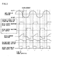
- the power supply unit 8 supplies electric power in an intermittent mode with synchronized timing such that the timing of the intermittent power supply is synchronized with the timing of the power supply to the winding 10 (in one-to-one synchronization). More specifically, the control output unit 5 controls the power supply unit 8 to supply the electric power in the intermittent mode.
- This adjustment of the timing of electric power supply to the timing of drive current flow makes it possible to allow the voltages (voltage waveforms) of the rechargeable battery 7 for left and right outputs to the winding 10, respectively, to be the same as each other at the timing when left and right control signals (electric power) for vibrating the vibrator 2 (left and right drive outputs as also indicated by solid arrow L and dashed arrow R in FIG.
- the time t (pulse width) of the power supply from the power supply unit 5 is determined so as to prevent overcharging of the rechargeable battery 7.
- the time t is preferably selected to make it possible for the power supply unit 8 to supply a current the same as the no-load current of the linear vibration motor, thereby preventing overcharging of the rechargeable battery 7 even during continuous operation of the linear vibration motor under no-load condition.
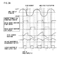
- the amplitude of the vibrator 2 varies with a load fluctuation, it is preferable to vary the amount of electric power, supplied from the power supply unit 8, according to the amplitude (amplitude value) of the vibrator 2. More specifically, when the amplitude of the vibrator 2 varies, the amplitude is stabilized such that when the amount of amplitude displacement decreases, the pulse width of the drive output is increased as shown in FIG. 3A , while when the amount of amplitude displacement increases, the pulse width of the drive output is reduced as shown in FIG. 3B .
- 3B shows, from top to bottom: amplitude of the vibrator 2; control signals for vibrating the vibrator 2 (left and right drive outputs as also indicated by solid arrow L and dashed arrow R in FIG. 1 ); drive current waveform; voltage waveform of rechargeable battery 7; and output waveform of power supply unit 8.
- the preferable variation of the amount of supplied electric power according to the variation or displacement of the amplitude, as described above, is such that when the pulse width of the drive output increases, the amount of electric supply from the power supply unit 8 is increased, while when the pulse width of the drive output decreases, the amount of electric supply from the power supply unit 8 is decreased.
- the pulse width of the drive output decreases due to the above described amplitude stabilization; this causes the drive current to decrease; this causes the current flowing into the rechargeable battery to increase; and this causes the voltage of the rechargeable battery to fluctuate.
- the pulse width of the drive output increases due to the above described amplitude stabilization; this causes the drive current to increase; this causes the current flowing out of the rechargeable battery to decrease; and this causes the voltage of the rechargeable battery to fluctuate.
- the amount of supplied electric power is varied according to the pulse width of the drive output as described above in the present embodiment, the voltage fluctuation of the rechargeable battery can be reduced, whereby the fluctuation of the amplitude displacement caused by the voltage fluctuation of the rechargeable battery can be minimized.
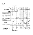
- the further preferable variation of the amount of supplied electric power, as described above, is such that when the voltage of the rechargeable battery 7 increases, the amount of electric supply from the power supply unit 8 is reduced as shown in FIG.
- FIG. 4 shows, from top to bottom: amplitude of the vibrator 2; control signals for vibrating the vibrator 2 (left and right drive outputs as also indicated by solid arrow L and dashed arrow R in FIG. 1 ); drive current waveform; voltage waveform of rechargeable battery 7 (instantaneous value); voltage waveform of rechargeable battery 7 (average value); and output waveform of power supply unit 8.
- the voltage of the rechargeable battery 7 can be smoothed by e.g. an integrator circuit to obtain its average value, which is to be fed back to the control output unit 5.
- the amplitude displacement decreases; this causes the pulse width of the drive output to increase due to the above described amplitude stabilization; this causes the drive current to increase; this causes the current flowing out of the rechargeable battery to decrease; and this causes the voltage of the rechargeable battery to further decrease.
- the amount of supplied electric power is varied according to the voltage of the rechargeable battery as described above in the present embodiment, the voltage fluctuation of the rechargeable battery can be reduced, and furthermore the fluctuation of the amplitude displacement can be minimized.
- FIG. 4 shows the case where the voltage of the rechargeable battery increases
- FIG. 5 shows the case where the voltage of the rechargeable battery decreases.
Landscapes
- Engineering & Computer Science (AREA)
- Power Engineering (AREA)
- Apparatuses For Generation Of Mechanical Vibrations (AREA)
- Reciprocating, Oscillating Or Vibrating Motors (AREA)
- Charge And Discharge Circuits For Batteries Or The Like (AREA)
- Control Of Linear Motors (AREA)
Claims (9)
- Linearer Vibrationsmotor mit:einem Stator (1), der mit einem von einem Permanentmagneten und einem eine Wicklung (10) einschließenden Elektromagneten versehen ist;einem Schwinger (2), der mit dem anderen von dem Permanentmagneten (2) und dem Elektromagneten versehen und so gelagert ist, dass er schwingen kann;einer Bewegungs-Detektionseinheit (6) zur Feststellung einer Bewegung des Vibrators;einer Steuer-Ausgangseinheit (6) zur Lieferung elektrischer Leistung an die Wicklung (10) des Elektromagneten auf der Grundlage eines Ausgangssignals der Bewegungs-Detektionseinheit (6) derart, dass eine Schwingung des Vibrators erzeugt wird;einer wiederaufladbaren Batterie (7) zur Lieferung elektrischer Leistung an die Steuer-Ausgangseinheit (5); undeiner Leistungsversorgungs-Einheit (8) zur Lieferung elektrischer Leistung an die Steuer-Ausgangseinheit (5) und an die wiederaufladbare Batterie (7);dadurch gekennzeichnet, dass die Leistungsversorgungs-Einheit (8) elektrische Leistung in einer intermittierenden Betriebsart mit einer synchronisierten Zeitsteuerung liefert, wobei die Zeitsteuerung der intermittierenden Leistungsversorgung mit der Zeitsteuerung der Leistungsversorgung an die Wicklung synchronisiert ist.
- Linearer Vibrationsmotor nach Anspruch 1,
bei dem die Steuer-Ausgangseinheit die Leistungsversorgungs-Einheit für eine Lieferung der elektrischen Leistung in der intermittierenden Betriebsart mit der synchronisierten Zeitsteuerung steuert. - Linearer Vibrationsmotor nach Anspruch 2,
bei dem die Bewegungs-Detektionseinheit die Amplitude des Vibrators feststellt, und
bei dem entsprechend der Amplitude des von der Bewegungs-Detektionseinheit festgestellten Amplitude des Vibrators die Steuer-Ausgangseinheit die Leistungsversorgungs-Einheit zur Änderung der Größe der elektrischen Leistung steuert, die von der Leistungsversorgungs-Einheit geliefert wird. - Linearer Vibrationsmotor nach Anspruch 3,
bei dem entsprechend der Spannung der wiederaufladbaren Batterie die Steuer-Ausgangseinheit die Leistungsversorgungs-Einheit zur Änderung der Größe der von der Leistungsversorgungs-Einheit gelieferten elektrischen Leistung steuert. - Linearer Vibrationsmotor nach Anspruch 3,
bei dem entsprechend der Temperatur der wiederaufladbaren Batterie und/oder der Leistungsversorgungs-Einheit die Steuer-Ausgangseinheit die Leistungsversorgungs-Einheit steuert, um die Größe der von der Leistungsversorgungs-Einheit gelieferten elektrischen Leistung zu ändern. - Linearer Vibrationsmotor nach Anspruch 3,
bei dem die Leistungsversorgungs-Einheit die Größe der von ihr gelieferten elektrischen Leistung durch Ändern der Impulsbreite ihres Ausgangssignals ändert. - Linearer Vibrationsmotor nach Anspruch 3,
bei dem die Leistungsversorgungs-Einheit die Größe der von ihr gelieferten elektrischen Leistung durch Ändern der Spannungsamplitude der von ihr abgegebenen Impulse ändert. - Linearer Vibrationsmotor nach Anspruch 3,
bei dem die Leistungsversorgungs-Einheit einen Strom liefert, der gleich dem lastfreien Strom des linearen Vibrationsmotors ist. - Linearer Vibrationsmotor nach Anspruch 3,
bei dem die Leistungsversorgungs-Einheit elektrische Leistung mit einer Frequenz der Zeitsteuerung liefert, die ein geradzahliges Vielfaches der Frequenz der Zeitsteuerung zur Zuführung elektrischer Leistung an die Wicklung ist.
Applications Claiming Priority (2)
| Application Number | Priority Date | Filing Date | Title |
|---|---|---|---|
| JP2004123260 | 2004-04-19 | ||
| JP2004123260A JP4315044B2 (ja) | 2004-04-19 | 2004-04-19 | リニア振動モータ |
Publications (3)
| Publication Number | Publication Date |
|---|---|
| EP1589654A2 EP1589654A2 (de) | 2005-10-26 |
| EP1589654A3 EP1589654A3 (de) | 2006-12-20 |
| EP1589654B1 true EP1589654B1 (de) | 2010-05-12 |
Family
ID=34940862
Family Applications (1)
| Application Number | Title | Priority Date | Filing Date |
|---|---|---|---|
| EP05252372A Expired - Lifetime EP1589654B1 (de) | 2004-04-19 | 2005-04-15 | Linearer Vibrationsmotor |
Country Status (6)
| Country | Link |
|---|---|
| US (1) | US7235936B2 (de) |
| EP (1) | EP1589654B1 (de) |
| JP (1) | JP4315044B2 (de) |
| CN (1) | CN1319265C (de) |
| AT (1) | ATE467948T1 (de) |
| DE (1) | DE602005021182D1 (de) |
Families Citing this family (29)
| Publication number | Priority date | Publication date | Assignee | Title |
|---|---|---|---|---|
| US8389906B2 (en) * | 2003-03-13 | 2013-03-05 | Radiancy Inc. | Electric shaver with debris removal element |
| DE602004018043D1 (de) * | 2004-07-06 | 2009-01-08 | Radiancy Inc | Rasierer mit haarvorwärmung |
| KR101151650B1 (ko) * | 2004-07-06 | 2012-06-08 | 라디언시 인크. | 전기 면도기 |
| US7598683B1 (en) | 2007-07-31 | 2009-10-06 | Lsi Industries, Inc. | Control of light intensity using pulses of a fixed duration and frequency |
| US8903577B2 (en) | 2009-10-30 | 2014-12-02 | Lsi Industries, Inc. | Traction system for electrically powered vehicles |
| US8604709B2 (en) | 2007-07-31 | 2013-12-10 | Lsi Industries, Inc. | Methods and systems for controlling electrical power to DC loads |
| JP4557029B2 (ja) * | 2008-03-26 | 2010-10-06 | パナソニック電工株式会社 | リニア振動モータの駆動制御方法 |
| JP2009240047A (ja) * | 2008-03-26 | 2009-10-15 | Panasonic Electric Works Co Ltd | 電磁アクチュエータの駆動方法 |
| US8476778B2 (en) * | 2009-03-09 | 2013-07-02 | Miw Associates, Llc | Energy generator |
| US8860337B2 (en) | 2009-05-18 | 2014-10-14 | Resonant Systems, Inc. | Linear vibration modules and linear-resonant vibration modules |
| CA2762809A1 (en) * | 2009-05-18 | 2010-11-25 | Resonant Systems, Inc. | Linear-resonant vibration module |
| JP5601845B2 (ja) * | 2010-01-28 | 2014-10-08 | セミコンダクター・コンポーネンツ・インダストリーズ・リミテッド・ライアビリティ・カンパニー | リニア振動モータの駆動制御回路 |
| JP5715759B2 (ja) * | 2010-01-28 | 2015-05-13 | セミコンダクター・コンポーネンツ・インダストリーズ・リミテッド・ライアビリティ・カンパニー | リニア振動モータの駆動制御回路 |
| JP5432057B2 (ja) * | 2010-05-13 | 2014-03-05 | セミコンダクター・コンポーネンツ・インダストリーズ・リミテッド・ライアビリティ・カンパニー | リニア振動モータの駆動制御回路 |
| JP5705457B2 (ja) * | 2010-05-13 | 2015-04-22 | セミコンダクター・コンポーネンツ・インダストリーズ・リミテッド・ライアビリティ・カンパニー | リニア振動モータの駆動制御回路 |
| JP5654387B2 (ja) * | 2011-02-28 | 2015-01-14 | パナソニックIpマネジメント株式会社 | リニア振動モータの駆動制御装置、リニア振動モータの駆動制御方法および小型電気機器 |
| CN103619209B (zh) * | 2011-06-22 | 2016-05-18 | 莱蒂恩思公司 | 毛发去除和再生抑制装置 |
| CN102724340A (zh) * | 2012-06-19 | 2012-10-10 | 广东欧珀移动通信有限公司 | 一种手机振动强弱的调节方法 |
| WO2014008459A1 (en) * | 2012-07-05 | 2014-01-09 | Resonant Systems, Inc. | Personal vibration appliance |
| WO2016131033A1 (en) * | 2015-02-13 | 2016-08-18 | Resonant Systems, Inc. | Oscillating-resonant-module controller |
| USD794871S1 (en) | 2016-01-15 | 2017-08-15 | Medline Industries, Inc. | Clipper |
| USD795497S1 (en) | 2016-01-15 | 2017-08-22 | Medline Industries, Inc. | Clipper |
| CN106100494B (zh) * | 2016-05-20 | 2019-04-26 | 瑞声科技(新加坡)有限公司 | 线性电机的驱动系统及其驱动方法 |
| USD802217S1 (en) | 2016-06-10 | 2017-11-07 | Medline Industries, Inc. | Clipper head |
| USD802214S1 (en) | 2016-06-10 | 2017-11-07 | Medline Industries, Inc. | Clipper head |
| USD802216S1 (en) | 2016-06-10 | 2017-11-07 | Medline Industries, Inc. | Clipper head |
| USD802215S1 (en) | 2016-06-10 | 2017-11-07 | Medline Industries, Inc. | Clipper head |
| TWI678880B (zh) * | 2018-04-11 | 2019-12-01 | 台睿精工股份有限公司 | 線性振動馬達、控制系統及煞停控制方法 |
| CN110994912B (zh) * | 2019-12-09 | 2022-06-03 | Oppo广东移动通信有限公司 | 振动装置及其控制方法、电子设备、存储介质 |
Family Cites Families (16)
| Publication number | Priority date | Publication date | Assignee | Title |
|---|---|---|---|---|
| NL9001909A (nl) * | 1990-08-30 | 1992-03-16 | Philips Nv | Elektromagnetische ondersteuning met enkelzijdige regelstromen. |
| DE4140586C2 (de) * | 1991-12-10 | 1995-12-21 | Clark Equipment Co N D Ges D S | Verfahren und Steuereinrichtung zur Steuerung des Stroms durch eine Magnetspule |
| US5539608A (en) * | 1993-02-25 | 1996-07-23 | Eaton Corporation | Electronic interlock for electromagnetic contactor |
| US5342176A (en) * | 1993-04-05 | 1994-08-30 | Sunpower, Inc. | Method and apparatus for measuring piston position in a free piston compressor |
| EP0652632B1 (de) * | 1993-10-08 | 2002-02-27 | Sawafuji Electric Co., Ltd. | Stromversorgung für vibrierende Kompressoren |
| JP3382061B2 (ja) | 1995-05-31 | 2003-03-04 | 松下電工株式会社 | リニア振動モータ |
| US5621603A (en) * | 1995-07-26 | 1997-04-15 | United Technologies Corporation | Pulse width modulated solenoid driver controller |
| JP3382070B2 (ja) * | 1995-08-28 | 2003-03-04 | 松下電工株式会社 | リニア振動モータの制御装置 |
| JPH1032989A (ja) * | 1996-07-15 | 1998-02-03 | Namiki Precision Jewel Co Ltd | 振動アクチュエータの駆動装置 |
| JP3674216B2 (ja) * | 1997-02-25 | 2005-07-20 | 松下電工株式会社 | リニア振動モータの駆動制御方法 |
| DE69937587T2 (de) * | 1998-04-23 | 2008-11-06 | Matsushita Electric Works, Ltd., Kadoma | Aktuator-Treiberschaltkreis |
| JP3661424B2 (ja) * | 1998-07-28 | 2005-06-15 | 松下電工株式会社 | リニア振動モータの駆動制御方法 |
| ATE397802T1 (de) * | 1999-06-21 | 2008-06-15 | Fisher & Paykel Appliances Ltd | Linearmotor |
| JP3931487B2 (ja) * | 1999-06-25 | 2007-06-13 | 松下電工株式会社 | リニア振動モータの駆動制御方法 |
| JP3791402B2 (ja) * | 2001-01-26 | 2006-06-28 | 松下電工株式会社 | リニア振動モータの駆動制御方法及び駆動制御装置 |
| JP3540311B2 (ja) * | 2002-05-31 | 2004-07-07 | 松下電器産業株式会社 | モータ駆動制御装置 |
-
2004
- 2004-04-19 JP JP2004123260A patent/JP4315044B2/ja not_active Expired - Fee Related
-
2005
- 2005-04-15 DE DE602005021182T patent/DE602005021182D1/de not_active Expired - Lifetime
- 2005-04-15 US US11/106,430 patent/US7235936B2/en not_active Expired - Lifetime
- 2005-04-15 CN CNB2005100657635A patent/CN1319265C/zh not_active Expired - Fee Related
- 2005-04-15 AT AT05252372T patent/ATE467948T1/de not_active IP Right Cessation
- 2005-04-15 EP EP05252372A patent/EP1589654B1/de not_active Expired - Lifetime
Also Published As
| Publication number | Publication date |
|---|---|
| US7235936B2 (en) | 2007-06-26 |
| EP1589654A3 (de) | 2006-12-20 |
| ATE467948T1 (de) | 2010-05-15 |
| US20050231045A1 (en) | 2005-10-20 |
| DE602005021182D1 (de) | 2010-06-24 |
| JP2005312133A (ja) | 2005-11-04 |
| CN1319265C (zh) | 2007-05-30 |
| CN1691491A (zh) | 2005-11-02 |
| JP4315044B2 (ja) | 2009-08-19 |
| EP1589654A2 (de) | 2005-10-26 |
Similar Documents
| Publication | Publication Date | Title |
|---|---|---|
| EP1589654B1 (de) | Linearer Vibrationsmotor | |
| EP0421332B1 (de) | Ladungssteuergerät für Fahrzeuge | |
| EP0952663B1 (de) | Treiberstufe für einen schwingenden Aktuator | |
| EP0654889B1 (de) | Antriebsvorrichtung für einen Ultraschallwellenmotor | |
| JP5593849B2 (ja) | 組電池の監視装置 | |
| EP2276160B1 (de) | Verfahren und vorrichtung zur erhöhung des wirkungsgrades eines schaltreglers bei geringer belastung | |
| US5034871A (en) | DC to DC converter with steady control of output DC voltage by monitoring output DC current | |
| EP2939863B1 (de) | Elektrisch angetriebenes fahrzeug | |
| KR100366777B1 (ko) | 압전트랜스의 구동방법 및 구동회로 | |
| EP2568590B1 (de) | Schaltnetzteil und Bilderzeugungsvorrichtung | |
| JP2009240045A (ja) | リニア振動モータの駆動制御方法 | |
| CN116250114B (zh) | 控制方法、装置、动力系统及电动汽车 | |
| JP2015116092A (ja) | 電動車両 | |
| JP2014036513A (ja) | モータ駆動装置 | |
| JP2006515148A (ja) | 適応電流プロファイルを用いたモーター制御システムおよび方法 | |
| JP2893917B2 (ja) | 振動機の駆動制御装置 | |
| KR100387502B1 (ko) | 전기 자동차용 병렬 충전 시스템 | |
| JP2006246667A (ja) | 電動機駆動装置 | |
| JPH08116665A (ja) | スイッチングレギュレータ | |
| JP2004327073A (ja) | 燃料電池発電システム | |
| JP2002260834A (ja) | 誘導加熱装置 | |
| HK1023233B (en) | Driving circuit for oscillatory actuator | |
| JPH07245944A (ja) | ポータブルコンピュータ用電源装置 | |
| JPH06197526A (ja) | 電子機器 | |
| JPH04156299A (ja) | インバータ励磁・誘導発電機システム |
Legal Events
| Date | Code | Title | Description |
|---|---|---|---|
| PUAI | Public reference made under article 153(3) epc to a published international application that has entered the european phase |
Free format text: ORIGINAL CODE: 0009012 |
|
| AK | Designated contracting states |
Kind code of ref document: A2 Designated state(s): AT BE BG CH CY CZ DE DK EE ES FI FR GB GR HU IE IS IT LI LT LU MC NL PL PT RO SE SI SK TR |
|
| AX | Request for extension of the european patent |
Extension state: AL BA HR LV MK YU |
|
| PUAL | Search report despatched |
Free format text: ORIGINAL CODE: 0009013 |
|
| AK | Designated contracting states |
Kind code of ref document: A3 Designated state(s): AT BE BG CH CY CZ DE DK EE ES FI FR GB GR HU IE IS IT LI LT LU MC NL PL PT RO SE SI SK TR |
|
| AX | Request for extension of the european patent |
Extension state: AL BA HR LV MK YU |
|
| 17P | Request for examination filed |
Effective date: 20070308 |
|
| AKX | Designation fees paid |
Designated state(s): AT BE BG CH CY CZ DE DK EE ES FI FR GB GR HU IE IS IT LI LT LU MC NL PL PT RO SE SI SK TR |
|
| RAP1 | Party data changed (applicant data changed or rights of an application transferred) |
Owner name: PANASONIC ELECTRIC WORKS CO., LTD. |
|
| GRAP | Despatch of communication of intention to grant a patent |
Free format text: ORIGINAL CODE: EPIDOSNIGR1 |
|
| GRAS | Grant fee paid |
Free format text: ORIGINAL CODE: EPIDOSNIGR3 |
|
| GRAA | (expected) grant |
Free format text: ORIGINAL CODE: 0009210 |
|
| AK | Designated contracting states |
Kind code of ref document: B1 Designated state(s): AT BE BG CH CY CZ DE DK EE ES FI FR GB GR HU IE IS IT LI LT LU MC NL PL PT RO SE SI SK TR |
|
| REG | Reference to a national code |
Ref country code: GB Ref legal event code: FG4D |
|
| REG | Reference to a national code |
Ref country code: CH Ref legal event code: EP |
|
| REG | Reference to a national code |
Ref country code: IE Ref legal event code: FG4D |
|
| REF | Corresponds to: |
Ref document number: 602005021182 Country of ref document: DE Date of ref document: 20100624 Kind code of ref document: P |
|
| REG | Reference to a national code |
Ref country code: NL Ref legal event code: VDEP Effective date: 20100512 |
|
| LTIE | Lt: invalidation of european patent or patent extension |
Effective date: 20100512 |
|
| PG25 | Lapsed in a contracting state [announced via postgrant information from national office to epo] |
Ref country code: LT Free format text: LAPSE BECAUSE OF FAILURE TO SUBMIT A TRANSLATION OF THE DESCRIPTION OR TO PAY THE FEE WITHIN THE PRESCRIBED TIME-LIMIT Effective date: 20100512 Ref country code: NL Free format text: LAPSE BECAUSE OF FAILURE TO SUBMIT A TRANSLATION OF THE DESCRIPTION OR TO PAY THE FEE WITHIN THE PRESCRIBED TIME-LIMIT Effective date: 20100512 Ref country code: SE Free format text: LAPSE BECAUSE OF FAILURE TO SUBMIT A TRANSLATION OF THE DESCRIPTION OR TO PAY THE FEE WITHIN THE PRESCRIBED TIME-LIMIT Effective date: 20100512 Ref country code: ES Free format text: LAPSE BECAUSE OF FAILURE TO SUBMIT A TRANSLATION OF THE DESCRIPTION OR TO PAY THE FEE WITHIN THE PRESCRIBED TIME-LIMIT Effective date: 20100823 |
|
| PG25 | Lapsed in a contracting state [announced via postgrant information from national office to epo] |
Ref country code: SI Free format text: LAPSE BECAUSE OF FAILURE TO SUBMIT A TRANSLATION OF THE DESCRIPTION OR TO PAY THE FEE WITHIN THE PRESCRIBED TIME-LIMIT Effective date: 20100512 Ref country code: AT Free format text: LAPSE BECAUSE OF FAILURE TO SUBMIT A TRANSLATION OF THE DESCRIPTION OR TO PAY THE FEE WITHIN THE PRESCRIBED TIME-LIMIT Effective date: 20100512 Ref country code: FI Free format text: LAPSE BECAUSE OF FAILURE TO SUBMIT A TRANSLATION OF THE DESCRIPTION OR TO PAY THE FEE WITHIN THE PRESCRIBED TIME-LIMIT Effective date: 20100512 Ref country code: IS Free format text: LAPSE BECAUSE OF FAILURE TO SUBMIT A TRANSLATION OF THE DESCRIPTION OR TO PAY THE FEE WITHIN THE PRESCRIBED TIME-LIMIT Effective date: 20100912 |
|
| PG25 | Lapsed in a contracting state [announced via postgrant information from national office to epo] |
Ref country code: GR Free format text: LAPSE BECAUSE OF FAILURE TO SUBMIT A TRANSLATION OF THE DESCRIPTION OR TO PAY THE FEE WITHIN THE PRESCRIBED TIME-LIMIT Effective date: 20100813 Ref country code: CY Free format text: LAPSE BECAUSE OF FAILURE TO SUBMIT A TRANSLATION OF THE DESCRIPTION OR TO PAY THE FEE WITHIN THE PRESCRIBED TIME-LIMIT Effective date: 20100512 Ref country code: PL Free format text: LAPSE BECAUSE OF FAILURE TO SUBMIT A TRANSLATION OF THE DESCRIPTION OR TO PAY THE FEE WITHIN THE PRESCRIBED TIME-LIMIT Effective date: 20100512 |
|
| PG25 | Lapsed in a contracting state [announced via postgrant information from national office to epo] |
Ref country code: PT Free format text: LAPSE BECAUSE OF FAILURE TO SUBMIT A TRANSLATION OF THE DESCRIPTION OR TO PAY THE FEE WITHIN THE PRESCRIBED TIME-LIMIT Effective date: 20100913 Ref country code: DK Free format text: LAPSE BECAUSE OF FAILURE TO SUBMIT A TRANSLATION OF THE DESCRIPTION OR TO PAY THE FEE WITHIN THE PRESCRIBED TIME-LIMIT Effective date: 20100512 Ref country code: EE Free format text: LAPSE BECAUSE OF FAILURE TO SUBMIT A TRANSLATION OF THE DESCRIPTION OR TO PAY THE FEE WITHIN THE PRESCRIBED TIME-LIMIT Effective date: 20100512 |
|
| PG25 | Lapsed in a contracting state [announced via postgrant information from national office to epo] |
Ref country code: SK Free format text: LAPSE BECAUSE OF FAILURE TO SUBMIT A TRANSLATION OF THE DESCRIPTION OR TO PAY THE FEE WITHIN THE PRESCRIBED TIME-LIMIT Effective date: 20100512 Ref country code: BE Free format text: LAPSE BECAUSE OF FAILURE TO SUBMIT A TRANSLATION OF THE DESCRIPTION OR TO PAY THE FEE WITHIN THE PRESCRIBED TIME-LIMIT Effective date: 20100512 Ref country code: CZ Free format text: LAPSE BECAUSE OF FAILURE TO SUBMIT A TRANSLATION OF THE DESCRIPTION OR TO PAY THE FEE WITHIN THE PRESCRIBED TIME-LIMIT Effective date: 20100512 Ref country code: RO Free format text: LAPSE BECAUSE OF FAILURE TO SUBMIT A TRANSLATION OF THE DESCRIPTION OR TO PAY THE FEE WITHIN THE PRESCRIBED TIME-LIMIT Effective date: 20100512 |
|
| PLBE | No opposition filed within time limit |
Free format text: ORIGINAL CODE: 0009261 |
|
| STAA | Information on the status of an ep patent application or granted ep patent |
Free format text: STATUS: NO OPPOSITION FILED WITHIN TIME LIMIT |
|
| 26N | No opposition filed |
Effective date: 20110215 |
|
| REG | Reference to a national code |
Ref country code: DE Ref legal event code: R097 Ref document number: 602005021182 Country of ref document: DE Effective date: 20110214 |
|
| PG25 | Lapsed in a contracting state [announced via postgrant information from national office to epo] |
Ref country code: MC Free format text: LAPSE BECAUSE OF NON-PAYMENT OF DUE FEES Effective date: 20110430 |
|
| REG | Reference to a national code |
Ref country code: CH Ref legal event code: PL |
|
| REG | Reference to a national code |
Ref country code: FR Ref legal event code: ST Effective date: 20111230 |
|
| PG25 | Lapsed in a contracting state [announced via postgrant information from national office to epo] |
Ref country code: FR Free format text: LAPSE BECAUSE OF NON-PAYMENT OF DUE FEES Effective date: 20110502 Ref country code: CH Free format text: LAPSE BECAUSE OF NON-PAYMENT OF DUE FEES Effective date: 20110430 Ref country code: LI Free format text: LAPSE BECAUSE OF NON-PAYMENT OF DUE FEES Effective date: 20110430 |
|
| REG | Reference to a national code |
Ref country code: IE Ref legal event code: MM4A |
|
| PG25 | Lapsed in a contracting state [announced via postgrant information from national office to epo] |
Ref country code: IE Free format text: LAPSE BECAUSE OF NON-PAYMENT OF DUE FEES Effective date: 20110415 |
|
| PG25 | Lapsed in a contracting state [announced via postgrant information from national office to epo] |
Ref country code: LU Free format text: LAPSE BECAUSE OF NON-PAYMENT OF DUE FEES Effective date: 20110415 |
|
| PGFP | Annual fee paid to national office [announced via postgrant information from national office to epo] |
Ref country code: GB Payment date: 20130410 Year of fee payment: 9 |
|
| PGFP | Annual fee paid to national office [announced via postgrant information from national office to epo] |
Ref country code: IT Payment date: 20130417 Year of fee payment: 9 |
|
| PG25 | Lapsed in a contracting state [announced via postgrant information from national office to epo] |
Ref country code: BG Free format text: LAPSE BECAUSE OF FAILURE TO SUBMIT A TRANSLATION OF THE DESCRIPTION OR TO PAY THE FEE WITHIN THE PRESCRIBED TIME-LIMIT Effective date: 20100812 Ref country code: TR Free format text: LAPSE BECAUSE OF FAILURE TO SUBMIT A TRANSLATION OF THE DESCRIPTION OR TO PAY THE FEE WITHIN THE PRESCRIBED TIME-LIMIT Effective date: 20100512 |
|
| PG25 | Lapsed in a contracting state [announced via postgrant information from national office to epo] |
Ref country code: HU Free format text: LAPSE BECAUSE OF FAILURE TO SUBMIT A TRANSLATION OF THE DESCRIPTION OR TO PAY THE FEE WITHIN THE PRESCRIBED TIME-LIMIT Effective date: 20100512 |
|
| GBPC | Gb: european patent ceased through non-payment of renewal fee |
Effective date: 20140415 |
|
| PG25 | Lapsed in a contracting state [announced via postgrant information from national office to epo] |
Ref country code: GB Free format text: LAPSE BECAUSE OF NON-PAYMENT OF DUE FEES Effective date: 20140415 |
|
| PG25 | Lapsed in a contracting state [announced via postgrant information from national office to epo] |
Ref country code: IT Free format text: LAPSE BECAUSE OF NON-PAYMENT OF DUE FEES Effective date: 20140415 |
|
| PGFP | Annual fee paid to national office [announced via postgrant information from national office to epo] |
Ref country code: DE Payment date: 20230222 Year of fee payment: 19 |
|
| REG | Reference to a national code |
Ref country code: DE Ref legal event code: R119 Ref document number: 602005021182 Country of ref document: DE |
|
| PG25 | Lapsed in a contracting state [announced via postgrant information from national office to epo] |
Ref country code: DE Free format text: LAPSE BECAUSE OF NON-PAYMENT OF DUE FEES Effective date: 20241105 |
|
| PG25 | Lapsed in a contracting state [announced via postgrant information from national office to epo] |
Ref country code: DE Free format text: LAPSE BECAUSE OF NON-PAYMENT OF DUE FEES Effective date: 20241105 |