EP1589312A1 - Munitionsmagazin - Google Patents
Munitionsmagazin Download PDFInfo
- Publication number
- EP1589312A1 EP1589312A1 EP05004889A EP05004889A EP1589312A1 EP 1589312 A1 EP1589312 A1 EP 1589312A1 EP 05004889 A EP05004889 A EP 05004889A EP 05004889 A EP05004889 A EP 05004889A EP 1589312 A1 EP1589312 A1 EP 1589312A1
- Authority
- EP
- European Patent Office
- Prior art keywords
- ammunition
- magazine
- loading
- channels
- magazine according
- Prior art date
- Legal status (The legal status is an assumption and is not a legal conclusion. Google has not performed a legal analysis and makes no representation as to the accuracy of the status listed.)
- Granted
Links
- 238000010276 construction Methods 0.000 claims abstract description 6
- 230000008878 coupling Effects 0.000 claims description 4
- 238000010168 coupling process Methods 0.000 claims description 4
- 238000005859 coupling reaction Methods 0.000 claims description 4
- 206010041662 Splinter Diseases 0.000 claims description 2
- 238000004804 winding Methods 0.000 claims 1
- 230000000712 assembly Effects 0.000 abstract 1
- 238000000429 assembly Methods 0.000 abstract 1
- 230000002411 adverse Effects 0.000 description 2
- 238000010304 firing Methods 0.000 description 2
- 230000001681 protective effect Effects 0.000 description 2
- 239000000126 substance Substances 0.000 description 2
- 208000027418 Wounds and injury Diseases 0.000 description 1
- 230000001133 acceleration Effects 0.000 description 1
- 238000005452 bending Methods 0.000 description 1
- 238000005266 casting Methods 0.000 description 1
- 230000008021 deposition Effects 0.000 description 1
- 239000002360 explosive Substances 0.000 description 1
- 239000012634 fragment Substances 0.000 description 1
- 238000003780 insertion Methods 0.000 description 1
- 230000037431 insertion Effects 0.000 description 1
- 239000000463 material Substances 0.000 description 1
- 239000002184 metal Substances 0.000 description 1
- 238000003801 milling Methods 0.000 description 1
- 239000011343 solid material Substances 0.000 description 1
- 238000003466 welding Methods 0.000 description 1
Images


Classifications
-
- F—MECHANICAL ENGINEERING; LIGHTING; HEATING; WEAPONS; BLASTING
- F41—WEAPONS
- F41A—FUNCTIONAL FEATURES OR DETAILS COMMON TO BOTH SMALLARMS AND ORDNANCE, e.g. CANNONS; MOUNTINGS FOR SMALLARMS OR ORDNANCE
- F41A9/00—Feeding or loading of ammunition; Magazines; Guiding means for the extracting of cartridges
- F41A9/61—Magazines
- F41A9/79—Magazines for belted ammunition
Definitions
- the invention relates to an ammunition magazine, in which one or the different Ammunition (s) can be so magazated that a contact of the management protection zones with modules of the magazine, foreign matter in the magazine or the adjacent construction is avoided.
- Ammunition generally has guide protection zones specified by the munitions manufacturer where a holding, leading or poking is very limited or can not be done at all. Particular attention should be paid to guard protection zones e.g. on the bottom of the cartridge below the primer and on sub-caliber ammunition in the area of the projectile protective cap. In previously known ammunition magazines may contact the guard protection zones with magazine components or components the adjacent construction can not be completely avoided. Unfavorable Operating conditions (high acceleration forces due to driving dynamics, dirt by handling under adverse climatic conditions, etc.) can thus damage ammunition and thus reduced performance data of the system or even to Implementation (firing) of ammunition in the system lead to the shooting of two different Types of ammunition from one or more weapons are currently two spatially separated ammunition boxes used. adversely is that a different loading of ammunition types only by reducing of the total ammunition stock is possible. When loading must also be on the location pay attention to the belt member, that is, in strapped ammunition that both types of ammunition are stored correctly in the magazines.
- a device for feeding ammunition from a stationarily arranged ammunition container describes DE 101 23 835 A1.
- An ammunition magazine is the DE 42 06 677 C2 removable.
- a device for feeding cartridge belts is disclosed in DE 35 10 308 C2.
- a double cartridge change feeder is described in DE 36 27 360 C1.
- An ammunition supply for unbalanced ammunition from DE 36 44 513 C1 provides an ammunition container with shelves in which the ammunition lie in one or more loops one above the other. Furthermore, the ammunition supply to an endless conveyor chain, which is guided over at least one drive wheel and a plurality of deflection devices.
- a device for feeding ammunition to a machine gun is provided by EP 0 0095 570 B1. From two magazines from the cartridges are supplied to the machine gun, with a simple switching of the weapon to ensure the supply of these two different types of ammunition, such as explosive ammunition on the one hand and armor-piercing ammunition on the other hand, the weapon. Based on this, the invention has the object to show a magazine in which contact of the guide protection zones of the stored in the magazine and to be taken during firing ammunition under all conditions of use is avoided.
- the invention is based on the idea to provide a magazine of one or more consisting of two ammunition channels with approximately rectangular or U-shaped cross-section, in which the design of the muntition channels correspondingly dimensioned open spaces (vibration chambers) on the example defined by the manufacturer leadership protection zones.
- the cross-section of the ammunition channels is designed in such a way that contact of individual guide protection zones of an ammunition within the magazine with magazine components or foreign substances and optionally outside of the magazine with the adjacent construction is preferably avoided under all operating conditions.
- Guide protection zones are usually defined by the manufacturer and include the areas of an ammunition that should not be touched. These areas are in practice at the ammunition head and at the ammunition base in the area of the primer.
- the leadership of the ammunition at the permissible zones is designed in such a way that disengagement of the ammunition from the intended vibration chambers due to the driving dynamics or other force is prevented. It is also advantageous that the deposition of foreign substances in the magazine is avoided. together in any shape (spiral, oval, rectangular, etc.) wrapped around a center (center) with one or more turns. In the center, the two ends of the ammunition channels are connected. As a result, depending on the individual case in the magazine different amounts of ammunition can be stored without reducing the total number of cartridges.
- the magazine can be made variable. For example, depending on tactical requirements, the ratio of armor piercing ammunition (KE ammunition) to fragment ammunition (HE ammunition) can be adjusted
- the ammunition channels be filled with ammunition.
- several Channels are filled via a common loading opening.
- the loading openings are to be loaded from above, below or to the side.
- the magazine may include strapped and non-belted ammunition, e.g. by Verwenbdung suitable conveyors in the channels, such as conveyor lines, conveyor belts etc., record.
- suitable conveyors such as conveyor lines, conveyor belts etc.
- the belt links become for both types of ammunition in always the same orientation introduced into the magazine Storable is the magazine and the ammunition in all layers, such as horizontal, vertically or diagonally in the room.
- the ammunition can be made by milling solid material, by welding Sheet metal on a base plate, by bending of hollow profiles, by casting etc. be made of any materials.
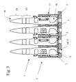
- 1, 2 and 4 are an ammunition magazine (magazine) with two from each other separate ammunition channels 2 and 3 with located in the middle of the magazine channel ends 4 and 5 marked.
- a Loading 6 at the ammunition 7 either one of the two ammunition channels 2, 3 can be supplied.
- the two ammunition channel ends 8 and 9 outside the Magazine 1 sets the interface of the magazine 1 to the other (not shown) Supplying the ammunition to the weapon.
- both ammunition channels 2 and 3 suitable conveying elements 10 and 11, which are of an electromotive type Drive 12 are driven in the middle of the magazine.
- 1 denotes an ammunition magazine (magazine), 2 a first ammunition in a first ammunition channel 3 and 4 a second, for example, other ammunition in an ammunition channel 5.
- the ammunition 2 and the ammunition 4 are each fed to a weapon not shown in the direction of M1 or M2.
- the graphically unspecified ammunition channel ends within the magazine 1 are connected to each other.
- 1 shows a possible embodiment of the described magazine 1 with parallel ammunition channels 2 and 3 entwined around the magazine center. Both inner ammunition channel ends 4 and 5 are located in the region of the common loading opening 6 in the center of the magazine 1, the outer ammunition channel ends 8 and 9 at the edge of the magazine.
- conveying elements 10 and 11 for both ammunition channels 2 and 3 and the necessary drive 12 are shown.
- Fig. 2 shows the magazine 1 with a strapped ammunition 7 in the fully loaded Ammunition channel 2.
- FIG. 3 shows a cross section through the parallel ammunition channels 2 and 3 of the magazine 1.
- a free space 14 is incorporated on the full channel length, the contact of the primer 13 with the magazine bottom 15 excludes.
- This space or this track 14 is additionally provided by openings in the magazine bottom 15, which allow an outflow of non-illustrated foreign bodies below the primer 13.
- the height of the magazine 1 is limited to the extent necessary for the guidance of the ammunition 7 in order to indemnify the protective zones defined by the manufacturer, for example F1 and F2, at an ammunition tip 16.
- a wall 17 of the ammunition channels 2 and 3 is undercut in the region of the belt member 18 such that a vertical movement and thus a contact of the ammunition 7 with the adjacent construction (eg roof of the storage room) is avoided.
- Fig. 4 shows the magazine with inserted into the loading port 6 ammunition 7.
- the ammunition channels 2 and 3 is at the loading port 6 due to open access the loading and unloading of the ammunition 7 and the Insertion into the ammunition channel to be filled possible.
- a coupling / cutting tool For the purpose of coupling or separating the ammunition belt during loading, Afterloading and unloading, a coupling / cutting tool can be used.
- the ammunition 1 is occupied by 36% in the ammunition channel 4 and the ammunition 3 by 64% in the ammunition channel 5, here strapped, in FIG. 2 by 13% and 87% and in FIG. 3 by 71% and 29%.
- this means in a Munitionsbe Glaung example a total of 200 cartridges that, for example, only 200 armor-piercing cartridges (ammunition 2) or only 200 anti-aircraft cartridges (ammunition 4) in the ammunition channels 3, 5 are involved.
- 72 armor-piercing (ammunition 2) on the ammunition channel 3 and 128 antiaircraft cartridges (splinter ammunition) can be supplied as ammunition 4 on the ammunition channel 5 of the weapon and so on.
- the two ammunition channels 3, 5 are intertwined around a center wrapped inside the magazine 1.
- the ammunition channels 3, 5 are parallel and not wound meandering. This has the advantage of less friction in the supply of ammunitions 2, 4 to the weapon.
Landscapes
- Engineering & Computer Science (AREA)
- General Engineering & Computer Science (AREA)
- Portable Nailing Machines And Staplers (AREA)
- Valve-Gear Or Valve Arrangements (AREA)
- Valve Device For Special Equipments (AREA)
- Charge And Discharge Circuits For Batteries Or The Like (AREA)
- Belt Conveyors (AREA)
Abstract
Description
Eine Vorrichtung zum Zuführen von Munition zu einer Maschinenwaffe liefert die EP 0 0095 570 B1. Von zwei Magazinen aus werden die Patronen der Maschinenwaffe zugeführt, wobei ein einfaches Umschalten der Waffe die Zuführung dieser zwei unterschiedlichen Munitionsarten, wie Sprengmunition einerseits und panzerbrechende Munition andererseits, zur Waffe gewährleistet.
Ausgehgend davon stellt sich die Erfindung die Aufgabe, ein Magazin aufzuzeigen, in dem ein Kontakt der Führungsschutzzonen der im Magazin gelagerten und beim Verschuss zu entnehmenden Munition unter allen Einsatzbedingungen vermieden wird.
Die Führung der Munition an den zulässigen Zonen ist dazu derart gestaltet, dass ein Ausrücken der Munition aus den vorgesehenen Schwingräumen aufgrund der Fahrdynamik oder sonstiger Krafteinwirkung unterbunden wird. Vorteilhaft ist auch, dass die Ablagerung von Fremdstoffen im Magazin vermieden wird. gemeinsam in beliebiger Form (spiralförmig, oval, rechteckig usw.) um ein Zentrum (Mittelpunkt) mit einer oder mit mehreren Windungen gewickelt werden. Im Zentrum werden die beiden Enden der Munitionskanäle miteinander verbunden.
Dadurch können abhängig vom Einzelfall im Magazin prozentual unterschiedliche Mengen Munition gelagert werden, ohne die Gesamtzahl der Patronen zu verringern. Das Magazin kann variabel gestaltet werden. So kann z.B. je nach taktischen Erfordernissen das Verhältnis von panzerbrechender Munition (KE-Munition) zu Splittermunition (HE - Munition) angepasst werden
- Fig. 1
- eine Darstellung eines Magazins mit zwei ineinander verschlungenen Munitionskanälen und gemeinsamer Beladeöffnung im MagazinSchnittdarstellung einer erste Variante der Zuführung,
- Fig. 2
- eine Darstellung eines Magazins aus Fig. 1 mit eingelegter Munition in einem MunitionskanalSchnittdarstellung einer zweite Variante der Zuführung,
- Fig. 3
- eine Schnittdarstellung des Magazins aus Fig. 1 mit beispielhaftem Kanalquerschnitt einer weitere Variante der Zuführung,.
- Fig. 4
- eine Darstellung eines Magazins aus Fig. 1 mit eingelegter Munition in der gemeinsamen Beladeöffnung.
Fig. 1 zeigt eine mögliche Ausführung des beschriebenen Magazins 1 mit parallel verlaufenden, um die Magazinmitte verschlungenen Munitionskanälen 2 und 3. Beide inneren Munitionskanalenden 4 und 5 befinden sich im Bereich der gemeinsamen Beladeöffnung 6 in der Mitte des Magazins 1, die äußeren Munitionskanalenden 8 und 9 am Magazinrand. Zudem sind Förderelemente 10 und 11 für beide Munitionskanäle 2 und 3 sowie der hierfür notwendige Antrieb 12 dargestellt.
Die Höhe des Magazins 1 ist auf das für die Führung der Munition 7 notwendige Maß begrenzt, um die beispielsweise vom Hersteller definierten Schutzzonen, hier F1 und F2, an einer Munitionsspitze 16 freizuhalten. Eine Wand 17 der Munitionskanäle 2 und 3 ist im Bereich des Gurtgliedes 18 derart hinterschnitten, dass eine Vertikalbewegung und somit ein Kontakt der Munition 7 mit der Anschlusskonstruktion (z.B. Dach des Lagerraumes) vermieden wird.
In der Praxis bedeutet dies bei einer Munitionsbestückung von beispielsweise insgesamt 200 Patronen, dass beispielsweise nur 200 panzerbrechende Patronen (Munition 2) oder nur 200 Flugabwehrpatronen (Munition 4) in den Munitionskanälen 3, 5 eingebunden sind. Nach Fig. 1 können dann beispielsweise 72 panzerbrechende (Munition 2) über den Munitionskanal 3 und 128 Flugabwehrpatronen (Splittermunition) als Munition 4 über den Munitionskanal 5 der Waffe zugeführt werden usw..
Claims (11)
Applications Claiming Priority (4)
| Application Number | Priority Date | Filing Date | Title |
|---|---|---|---|
| DE102004019501 | 2004-04-22 | ||
| DE102004019501 | 2004-04-22 | ||
| DE102004035634 | 2004-07-22 | ||
| DE102004035634A DE102004035634A1 (de) | 2004-04-22 | 2004-07-22 | Munitionsmagazin |
Publications (2)
| Publication Number | Publication Date |
|---|---|
| EP1589312A1 true EP1589312A1 (de) | 2005-10-26 |
| EP1589312B1 EP1589312B1 (de) | 2007-05-30 |
Family
ID=34934088
Family Applications (1)
| Application Number | Title | Priority Date | Filing Date |
|---|---|---|---|
| EP05004889A Expired - Lifetime EP1589312B1 (de) | 2004-04-22 | 2005-03-05 | Munitionsmagazin |
Country Status (4)
| Country | Link |
|---|---|
| EP (1) | EP1589312B1 (de) |
| AT (1) | ATE363638T1 (de) |
| DE (2) | DE102004035634A1 (de) |
| ES (1) | ES2286729T3 (de) |
Cited By (1)
| Publication number | Priority date | Publication date | Assignee | Title |
|---|---|---|---|---|
| WO2017080800A1 (fr) | 2015-11-10 | 2017-05-18 | Cmi Defence S.A. | Dispositif d'alimentation en munitions de moyen calibre à plateau tournant |
Families Citing this family (4)
| Publication number | Priority date | Publication date | Assignee | Title |
|---|---|---|---|---|
| DE102008026679A1 (de) | 2008-06-04 | 2009-12-17 | Rheinmetall Landsysteme Gmbh | Munitionsmagazin für gegurtete Munition |
| DE102009031285B4 (de) | 2009-06-30 | 2016-11-03 | Rheinmetall Landsysteme Gmbh | Wegwurfvorrichtung für getrennte Gurtglieder |
| DE102009031286A1 (de) | 2009-06-30 | 2011-01-05 | Rheinmetall Landsysteme Gmbh | Trennvorrichtung für Gurtglieder |
| DE102009034889A1 (de) | 2009-07-27 | 2011-02-03 | Rheinmetall Landsysteme Gmbh | Schaltbarer Freilauf |
Citations (11)
| Publication number | Priority date | Publication date | Assignee | Title |
|---|---|---|---|---|
| EP0152549A1 (de) * | 1983-12-22 | 1985-08-28 | Werkzeugmaschinenfabrik Oerlikon-Bührle AG | Vorrichtung zum Zuführen von Patronen zu einer Feuerwaffe |
| EP0095570B1 (de) | 1982-05-26 | 1986-07-30 | KUKA Wehrtechnik GmbH | Vorrichtung zum Zuführen von Munition zu einer Maschinenwaffe |
| US4674392A (en) * | 1982-11-26 | 1987-06-23 | Heckler & Koch Gmbh | Cartridge feed mechanism |
| DE3635467C1 (en) | 1986-10-18 | 1987-11-05 | Rheinmetall Gmbh | Flexible belt channel for feeding belted ammunition to an automatic firearm |
| EP0365120A1 (de) * | 1988-08-15 | 1990-04-25 | General Electric Company | Fördereinrichtung für Artikel |
| US4951547A (en) * | 1988-09-28 | 1990-08-28 | Werkzeugmaschinenfabrik Oerlikon-Buhrle Ag | Endless storage and conveyor chain in an ammunition magazine |
| DE3627360C1 (de) | 1986-08-16 | 1992-04-09 | Rheinmetall Gmbh | Doppel-Patronen-Wechsel-Zufuehrer fuer eine fremdangetriebene Maschinenwaffe |
| US5107750A (en) * | 1986-12-24 | 1992-04-28 | Dornier Gmbh | Feeding ammunition |
| DE3510308C2 (de) | 1985-03-22 | 1993-08-19 | Kuka Wehrtechnik Gmbh, 8900 Augsburg, De | |
| DE4206677C1 (de) | 1992-02-28 | 1993-09-02 | Siemens Ag, 80333 Muenchen, De | |
| DE10123835A1 (de) | 2001-05-16 | 2002-11-21 | Krauss Maffei Wegmann Gmbh & C | Vorrichtung zur Zuführung von Munition aus einem stationär angeordneten Munitionsbehälter zu einer höhenrichtbaren Waffe |
-
2004
- 2004-07-22 DE DE102004035634A patent/DE102004035634A1/de not_active Withdrawn
-
2005
- 2005-03-05 ES ES05004889T patent/ES2286729T3/es not_active Expired - Lifetime
- 2005-03-05 DE DE502005000761T patent/DE502005000761D1/de not_active Expired - Lifetime
- 2005-03-05 EP EP05004889A patent/EP1589312B1/de not_active Expired - Lifetime
- 2005-03-05 AT AT05004889T patent/ATE363638T1/de active
Patent Citations (12)
| Publication number | Priority date | Publication date | Assignee | Title |
|---|---|---|---|---|
| EP0095570B1 (de) | 1982-05-26 | 1986-07-30 | KUKA Wehrtechnik GmbH | Vorrichtung zum Zuführen von Munition zu einer Maschinenwaffe |
| US4674392A (en) * | 1982-11-26 | 1987-06-23 | Heckler & Koch Gmbh | Cartridge feed mechanism |
| EP0152549A1 (de) * | 1983-12-22 | 1985-08-28 | Werkzeugmaschinenfabrik Oerlikon-Bührle AG | Vorrichtung zum Zuführen von Patronen zu einer Feuerwaffe |
| DE3510308C2 (de) | 1985-03-22 | 1993-08-19 | Kuka Wehrtechnik Gmbh, 8900 Augsburg, De | |
| DE3627360C1 (de) | 1986-08-16 | 1992-04-09 | Rheinmetall Gmbh | Doppel-Patronen-Wechsel-Zufuehrer fuer eine fremdangetriebene Maschinenwaffe |
| DE3635467C1 (en) | 1986-10-18 | 1987-11-05 | Rheinmetall Gmbh | Flexible belt channel for feeding belted ammunition to an automatic firearm |
| US5107750A (en) * | 1986-12-24 | 1992-04-28 | Dornier Gmbh | Feeding ammunition |
| DE3644513C1 (de) | 1986-12-24 | 1992-08-27 | Dornier Gmbh | Munitionszufuehrung |
| EP0365120A1 (de) * | 1988-08-15 | 1990-04-25 | General Electric Company | Fördereinrichtung für Artikel |
| US4951547A (en) * | 1988-09-28 | 1990-08-28 | Werkzeugmaschinenfabrik Oerlikon-Buhrle Ag | Endless storage and conveyor chain in an ammunition magazine |
| DE4206677C1 (de) | 1992-02-28 | 1993-09-02 | Siemens Ag, 80333 Muenchen, De | |
| DE10123835A1 (de) | 2001-05-16 | 2002-11-21 | Krauss Maffei Wegmann Gmbh & C | Vorrichtung zur Zuführung von Munition aus einem stationär angeordneten Munitionsbehälter zu einer höhenrichtbaren Waffe |
Cited By (2)
| Publication number | Priority date | Publication date | Assignee | Title |
|---|---|---|---|---|
| WO2017080800A1 (fr) | 2015-11-10 | 2017-05-18 | Cmi Defence S.A. | Dispositif d'alimentation en munitions de moyen calibre à plateau tournant |
| US10591233B2 (en) * | 2015-11-10 | 2020-03-17 | Cmi Defence S.A. | Medium-caliber ammunition supply device with turntable |
Also Published As
| Publication number | Publication date |
|---|---|
| ATE363638T1 (de) | 2007-06-15 |
| ES2286729T3 (es) | 2007-12-01 |
| DE102004035634A1 (de) | 2005-11-10 |
| DE502005000761D1 (de) | 2007-07-12 |
| EP1589312B1 (de) | 2007-05-30 |
Similar Documents
| Publication | Publication Date | Title |
|---|---|---|
| EP2183540B1 (de) | Munitionsbevorratung | |
| EP1061323B1 (de) | Gepanzertes Transportkraftfahrzeug | |
| DE3200726C2 (de) | Magazin für die Speicherung von Munitionsteilen | |
| EP3988889B1 (de) | Gehäuse für ein patronenmagazin für eine handfeuerwaffe und patronenmagazin für eine handfeuerwaffe | |
| DE102009009082A1 (de) | Wirkmittelwurfsystem zum Abschuss nicht-letaler Wirkmittel von einem Fahrzeug, insbesondere einem Polizei-oder Militärfahrzeug | |
| DE69126197T2 (de) | Bandförderer | |
| DE2501424C2 (de) | Munitionsaufnahme- und Ladevorrichtung für eine großkalibrige Feuerwaffe | |
| EP1589312A1 (de) | Munitionsmagazin | |
| DE3022410C2 (de) | Einrichtung zum Zuführen von Geschoßmunition in einem Panzerfahrzeug | |
| DE8215344U1 (de) | Vorrichtung zum zufuehren von munition zu einer maschinenwaffe | |
| DE3701713C2 (de) | ||
| EP0290031B1 (de) | Vorrichtung zum Zuführen von Munition aus einem Munitionsbehälter zu einer automatischen Feuerwaffe | |
| EP1738130B1 (de) | Munitionsmagazin | |
| DE69123338T2 (de) | Magazin und Förderband | |
| DE19644524C2 (de) | Geschützturm für Panzerfahrzeuge | |
| DE102009058567A1 (de) | Treibladungsmagazin sowie mit einem Treibladungsmagazin ausgestatteter Kampfraum | |
| DE3020482C2 (de) | ||
| DE3936469C2 (de) | Munitionsmagazin zur Lagerung von Patronen | |
| EP0635695B1 (de) | Kampffahrzeug, insbesondere Panzerhaubitze, mit Munitionsmagazinen | |
| DE102020113534B3 (de) | Magazin-Vorrichtung für Schusswaffen mit optimierter Raumnutzung | |
| DE69520206T2 (de) | Kompaktes förderkettensystem | |
| EP2331902A1 (de) | Patronenmunition | |
| DE4131280A1 (de) | Kampfpanzerturm | |
| EP2131136B1 (de) | Munitionsmagazin für gegurtete Munition | |
| EP4107465B1 (de) | Magazin |
Legal Events
| Date | Code | Title | Description |
|---|---|---|---|
| PUAI | Public reference made under article 153(3) epc to a published international application that has entered the european phase |
Free format text: ORIGINAL CODE: 0009012 |
|
| 17P | Request for examination filed |
Effective date: 20050604 |
|
| AK | Designated contracting states |
Kind code of ref document: A1 Designated state(s): AT BE BG CH CY CZ DE DK EE ES FI FR GB GR HU IE IS IT LI LT LU MC NL PL PT RO SE SI SK TR |
|
| AX | Request for extension of the european patent |
Extension state: AL BA HR LV MK YU |
|
| RAP1 | Party data changed (applicant data changed or rights of an application transferred) |
Owner name: RHEINMETALL LANDSYSTEME GMBH |
|
| AKX | Designation fees paid |
Designated state(s): AT BE BG CH CY CZ DE DK EE ES FI FR GB GR HU IE IS IT LI LT LU MC NL PL PT RO SE SI SK TR |
|
| GRAP | Despatch of communication of intention to grant a patent |
Free format text: ORIGINAL CODE: EPIDOSNIGR1 |
|
| GRAS | Grant fee paid |
Free format text: ORIGINAL CODE: EPIDOSNIGR3 |
|
| GRAA | (expected) grant |
Free format text: ORIGINAL CODE: 0009210 |
|
| AK | Designated contracting states |
Kind code of ref document: B1 Designated state(s): AT BE BG CH CY CZ DE DK EE ES FI FR GB GR HU IE IS IT LI LT LU MC NL PL PT RO SE SI SK TR |
|
| PG25 | Lapsed in a contracting state [announced via postgrant information from national office to epo] |
Ref country code: FI Free format text: LAPSE BECAUSE OF FAILURE TO SUBMIT A TRANSLATION OF THE DESCRIPTION OR TO PAY THE FEE WITHIN THE PRESCRIBED TIME-LIMIT Effective date: 20070530 |
|
| REG | Reference to a national code |
Ref country code: GB Ref legal event code: FG4D Free format text: NOT ENGLISH |
|
| REG | Reference to a national code |
Ref country code: CH Ref legal event code: EP |
|
| REG | Reference to a national code |
Ref country code: IE Ref legal event code: FG4D Free format text: LANGUAGE OF EP DOCUMENT: GERMAN |
|
| REF | Corresponds to: |
Ref document number: 502005000761 Country of ref document: DE Date of ref document: 20070712 Kind code of ref document: P |
|
| REG | Reference to a national code |
Ref country code: SE Ref legal event code: TRGR |
|
| PG25 | Lapsed in a contracting state [announced via postgrant information from national office to epo] |
Ref country code: IS Free format text: LAPSE BECAUSE OF NON-PAYMENT OF DUE FEES Effective date: 20070930 |
|
| ET | Fr: translation filed | ||
| GBT | Gb: translation of ep patent filed (gb section 77(6)(a)/1977) |
Effective date: 20070926 |
|
| PG25 | Lapsed in a contracting state [announced via postgrant information from national office to epo] |
Ref country code: PL Free format text: LAPSE BECAUSE OF FAILURE TO SUBMIT A TRANSLATION OF THE DESCRIPTION OR TO PAY THE FEE WITHIN THE PRESCRIBED TIME-LIMIT Effective date: 20070530 |
|
| REG | Reference to a national code |
Ref country code: ES Ref legal event code: FG2A Ref document number: 2286729 Country of ref document: ES Kind code of ref document: T3 |
|
| REG | Reference to a national code |
Ref country code: IE Ref legal event code: FD4D |
|
| PG25 | Lapsed in a contracting state [announced via postgrant information from national office to epo] |
Ref country code: IE Free format text: LAPSE BECAUSE OF FAILURE TO SUBMIT A TRANSLATION OF THE DESCRIPTION OR TO PAY THE FEE WITHIN THE PRESCRIBED TIME-LIMIT Effective date: 20070530 Ref country code: CZ Free format text: LAPSE BECAUSE OF FAILURE TO SUBMIT A TRANSLATION OF THE DESCRIPTION OR TO PAY THE FEE WITHIN THE PRESCRIBED TIME-LIMIT Effective date: 20070530 Ref country code: SI Free format text: LAPSE BECAUSE OF FAILURE TO SUBMIT A TRANSLATION OF THE DESCRIPTION OR TO PAY THE FEE WITHIN THE PRESCRIBED TIME-LIMIT Effective date: 20070530 Ref country code: BG Free format text: LAPSE BECAUSE OF FAILURE TO SUBMIT A TRANSLATION OF THE DESCRIPTION OR TO PAY THE FEE WITHIN THE PRESCRIBED TIME-LIMIT Effective date: 20070830 Ref country code: PT Free format text: LAPSE BECAUSE OF FAILURE TO SUBMIT A TRANSLATION OF THE DESCRIPTION OR TO PAY THE FEE WITHIN THE PRESCRIBED TIME-LIMIT Effective date: 20071030 Ref country code: DK Free format text: LAPSE BECAUSE OF FAILURE TO SUBMIT A TRANSLATION OF THE DESCRIPTION OR TO PAY THE FEE WITHIN THE PRESCRIBED TIME-LIMIT Effective date: 20070530 |
|
| PG25 | Lapsed in a contracting state [announced via postgrant information from national office to epo] |
Ref country code: LT Free format text: LAPSE BECAUSE OF FAILURE TO SUBMIT A TRANSLATION OF THE DESCRIPTION OR TO PAY THE FEE WITHIN THE PRESCRIBED TIME-LIMIT Effective date: 20070530 Ref country code: SK Free format text: LAPSE BECAUSE OF FAILURE TO SUBMIT A TRANSLATION OF THE DESCRIPTION OR TO PAY THE FEE WITHIN THE PRESCRIBED TIME-LIMIT Effective date: 20070530 |
|
| PLBE | No opposition filed within time limit |
Free format text: ORIGINAL CODE: 0009261 |
|
| STAA | Information on the status of an ep patent application or granted ep patent |
Free format text: STATUS: NO OPPOSITION FILED WITHIN TIME LIMIT |
|
| PG25 | Lapsed in a contracting state [announced via postgrant information from national office to epo] |
Ref country code: GR Free format text: LAPSE BECAUSE OF FAILURE TO SUBMIT A TRANSLATION OF THE DESCRIPTION OR TO PAY THE FEE WITHIN THE PRESCRIBED TIME-LIMIT Effective date: 20070831 |
|
| 26N | No opposition filed |
Effective date: 20080303 |
|
| PG25 | Lapsed in a contracting state [announced via postgrant information from national office to epo] |
Ref country code: RO Free format text: LAPSE BECAUSE OF FAILURE TO SUBMIT A TRANSLATION OF THE DESCRIPTION OR TO PAY THE FEE WITHIN THE PRESCRIBED TIME-LIMIT Effective date: 20070530 |
|
| BERE | Be: lapsed |
Owner name: RHEINMETALL LANDSYSTEME G.M.B.H. Effective date: 20080331 |
|
| PG25 | Lapsed in a contracting state [announced via postgrant information from national office to epo] |
Ref country code: MC Free format text: LAPSE BECAUSE OF NON-PAYMENT OF DUE FEES Effective date: 20080331 |
|
| PG25 | Lapsed in a contracting state [announced via postgrant information from national office to epo] |
Ref country code: EE Free format text: LAPSE BECAUSE OF FAILURE TO SUBMIT A TRANSLATION OF THE DESCRIPTION OR TO PAY THE FEE WITHIN THE PRESCRIBED TIME-LIMIT Effective date: 20070530 |
|
| PG25 | Lapsed in a contracting state [announced via postgrant information from national office to epo] |
Ref country code: BE Free format text: LAPSE BECAUSE OF NON-PAYMENT OF DUE FEES Effective date: 20080331 |
|
| PG25 | Lapsed in a contracting state [announced via postgrant information from national office to epo] |
Ref country code: CY Free format text: LAPSE BECAUSE OF FAILURE TO SUBMIT A TRANSLATION OF THE DESCRIPTION OR TO PAY THE FEE WITHIN THE PRESCRIBED TIME-LIMIT Effective date: 20070530 |
|
| REG | Reference to a national code |
Ref country code: CH Ref legal event code: PL |
|
| PG25 | Lapsed in a contracting state [announced via postgrant information from national office to epo] |
Ref country code: LI Free format text: LAPSE BECAUSE OF NON-PAYMENT OF DUE FEES Effective date: 20090331 Ref country code: CH Free format text: LAPSE BECAUSE OF NON-PAYMENT OF DUE FEES Effective date: 20090331 |
|
| PG25 | Lapsed in a contracting state [announced via postgrant information from national office to epo] |
Ref country code: HU Free format text: LAPSE BECAUSE OF FAILURE TO SUBMIT A TRANSLATION OF THE DESCRIPTION OR TO PAY THE FEE WITHIN THE PRESCRIBED TIME-LIMIT Effective date: 20071201 Ref country code: LU Free format text: LAPSE BECAUSE OF NON-PAYMENT OF DUE FEES Effective date: 20080305 |
|
| PG25 | Lapsed in a contracting state [announced via postgrant information from national office to epo] |
Ref country code: TR Free format text: LAPSE BECAUSE OF FAILURE TO SUBMIT A TRANSLATION OF THE DESCRIPTION OR TO PAY THE FEE WITHIN THE PRESCRIBED TIME-LIMIT Effective date: 20070530 |
|
| REG | Reference to a national code |
Ref country code: FR Ref legal event code: PLFP Year of fee payment: 12 |
|
| PGFP | Annual fee paid to national office [announced via postgrant information from national office to epo] |
Ref country code: NL Payment date: 20160321 Year of fee payment: 12 Ref country code: ES Payment date: 20160309 Year of fee payment: 12 |
|
| PGFP | Annual fee paid to national office [announced via postgrant information from national office to epo] |
Ref country code: AT Payment date: 20160322 Year of fee payment: 12 |
|
| REG | Reference to a national code |
Ref country code: FR Ref legal event code: PLFP Year of fee payment: 13 |
|
| REG | Reference to a national code |
Ref country code: NL Ref legal event code: MM Effective date: 20170401 |
|
| REG | Reference to a national code |
Ref country code: AT Ref legal event code: MM01 Ref document number: 363638 Country of ref document: AT Kind code of ref document: T Effective date: 20170305 |
|
| PG25 | Lapsed in a contracting state [announced via postgrant information from national office to epo] |
Ref country code: AT Free format text: LAPSE BECAUSE OF NON-PAYMENT OF DUE FEES Effective date: 20170305 Ref country code: NL Free format text: LAPSE BECAUSE OF NON-PAYMENT OF DUE FEES Effective date: 20170401 |
|
| REG | Reference to a national code |
Ref country code: FR Ref legal event code: PLFP Year of fee payment: 14 |
|
| REG | Reference to a national code |
Ref country code: ES Ref legal event code: FD2A Effective date: 20180704 |
|
| PG25 | Lapsed in a contracting state [announced via postgrant information from national office to epo] |
Ref country code: ES Free format text: LAPSE BECAUSE OF NON-PAYMENT OF DUE FEES Effective date: 20170306 |
|
| PGFP | Annual fee paid to national office [announced via postgrant information from national office to epo] |
Ref country code: DE Payment date: 20240320 Year of fee payment: 20 Ref country code: GB Payment date: 20240320 Year of fee payment: 20 |
|
| PGFP | Annual fee paid to national office [announced via postgrant information from national office to epo] |
Ref country code: SE Payment date: 20240320 Year of fee payment: 20 Ref country code: IT Payment date: 20240329 Year of fee payment: 20 Ref country code: FR Payment date: 20240321 Year of fee payment: 20 |
|
| REG | Reference to a national code |
Ref country code: DE Ref legal event code: R071 Ref document number: 502005000761 Country of ref document: DE |
|
| REG | Reference to a national code |
Ref country code: GB Ref legal event code: PE20 Expiry date: 20250304 |
|
| PG25 | Lapsed in a contracting state [announced via postgrant information from national office to epo] |
Ref country code: GB Free format text: LAPSE BECAUSE OF EXPIRATION OF PROTECTION Effective date: 20250304 |
|
| REG | Reference to a national code |
Ref country code: SE Ref legal event code: EUG |