EP1589232A2 - Hydraulische Steuereinrichtung - Google Patents
Hydraulische Steuereinrichtung Download PDFInfo
- Publication number
- EP1589232A2 EP1589232A2 EP05008582A EP05008582A EP1589232A2 EP 1589232 A2 EP1589232 A2 EP 1589232A2 EP 05008582 A EP05008582 A EP 05008582A EP 05008582 A EP05008582 A EP 05008582A EP 1589232 A2 EP1589232 A2 EP 1589232A2
- Authority
- EP
- European Patent Office
- Prior art keywords
- valve
- seat
- valves
- control device
- hydraulic control
- Prior art date
- Legal status (The legal status is an assumption and is not a legal conclusion. Google has not performed a legal analysis and makes no representation as to the accuracy of the status listed.)
- Withdrawn
Links
- 230000001007 puffing effect Effects 0.000 claims 1
- 239000003921 oil Substances 0.000 description 42
- 239000010720 hydraulic oil Substances 0.000 description 24
- RZVAJINKPMORJF-UHFFFAOYSA-N Acetaminophen Chemical class CC(=O)NC1=CC=C(O)C=C1 RZVAJINKPMORJF-UHFFFAOYSA-N 0.000 description 10
- 238000010586 diagram Methods 0.000 description 4
- 238000006073 displacement reaction Methods 0.000 description 4
- 238000010276 construction Methods 0.000 description 3
- 230000005611 electricity Effects 0.000 description 3
- 230000008901 benefit Effects 0.000 description 2
- 230000000903 blocking effect Effects 0.000 description 2
- 230000008859 change Effects 0.000 description 2
- 238000011161 development Methods 0.000 description 2
- 230000018109 developmental process Effects 0.000 description 2
- 230000000694 effects Effects 0.000 description 2
- 238000004519 manufacturing process Methods 0.000 description 2
- 230000004913 activation Effects 0.000 description 1
- 230000001934 delay Effects 0.000 description 1
- 230000001419 dependent effect Effects 0.000 description 1
- 230000000994 depressogenic effect Effects 0.000 description 1
- 238000005516 engineering process Methods 0.000 description 1
- 238000000034 method Methods 0.000 description 1
- 230000008569 process Effects 0.000 description 1
- 239000013589 supplement Substances 0.000 description 1
Images
Classifications
-
- E—FIXED CONSTRUCTIONS
- E02—HYDRAULIC ENGINEERING; FOUNDATIONS; SOIL SHIFTING
- E02F—DREDGING; SOIL-SHIFTING
- E02F9/00—Component parts of dredgers or soil-shifting machines, not restricted to one of the kinds covered by groups E02F3/00 - E02F7/00
- E02F9/20—Drives; Control devices
- E02F9/22—Hydraulic or pneumatic drives
- E02F9/2264—Arrangements or adaptations of elements for hydraulic drives
- E02F9/2267—Valves or distributors
-
- E—FIXED CONSTRUCTIONS
- E02—HYDRAULIC ENGINEERING; FOUNDATIONS; SOIL SHIFTING
- E02F—DREDGING; SOIL-SHIFTING
- E02F9/00—Component parts of dredgers or soil-shifting machines, not restricted to one of the kinds covered by groups E02F3/00 - E02F7/00
- E02F9/20—Drives; Control devices
- E02F9/22—Hydraulic or pneumatic drives
- E02F9/226—Safety arrangements, e.g. hydraulic driven fans, preventing cavitation, leakage, overheating
-
- E—FIXED CONSTRUCTIONS
- E02—HYDRAULIC ENGINEERING; FOUNDATIONS; SOIL SHIFTING
- E02F—DREDGING; SOIL-SHIFTING
- E02F9/00—Component parts of dredgers or soil-shifting machines, not restricted to one of the kinds covered by groups E02F3/00 - E02F7/00
- E02F9/20—Drives; Control devices
- E02F9/22—Hydraulic or pneumatic drives
- E02F9/2264—Arrangements or adaptations of elements for hydraulic drives
- E02F9/2271—Actuators and supports therefor and protection therefor
-
- F—MECHANICAL ENGINEERING; LIGHTING; HEATING; WEAPONS; BLASTING
- F15—FLUID-PRESSURE ACTUATORS; HYDRAULICS OR PNEUMATICS IN GENERAL
- F15B—SYSTEMS ACTING BY MEANS OF FLUIDS IN GENERAL; FLUID-PRESSURE ACTUATORS, e.g. SERVOMOTORS; DETAILS OF FLUID-PRESSURE SYSTEMS, NOT OTHERWISE PROVIDED FOR
- F15B11/00—Servomotor systems without provision for follow-up action; Circuits therefor
- F15B11/003—Systems with load-holding valves
-
- F—MECHANICAL ENGINEERING; LIGHTING; HEATING; WEAPONS; BLASTING
- F15—FLUID-PRESSURE ACTUATORS; HYDRAULICS OR PNEUMATICS IN GENERAL
- F15B—SYSTEMS ACTING BY MEANS OF FLUIDS IN GENERAL; FLUID-PRESSURE ACTUATORS, e.g. SERVOMOTORS; DETAILS OF FLUID-PRESSURE SYSTEMS, NOT OTHERWISE PROVIDED FOR
- F15B11/00—Servomotor systems without provision for follow-up action; Circuits therefor
- F15B11/02—Systems essentially incorporating special features for controlling the speed or actuating force of an output member
- F15B11/024—Systems essentially incorporating special features for controlling the speed or actuating force of an output member by means of differential connection of the servomotor lines, e.g. regenerative circuits
-
- F—MECHANICAL ENGINEERING; LIGHTING; HEATING; WEAPONS; BLASTING
- F15—FLUID-PRESSURE ACTUATORS; HYDRAULICS OR PNEUMATICS IN GENERAL
- F15B—SYSTEMS ACTING BY MEANS OF FLUIDS IN GENERAL; FLUID-PRESSURE ACTUATORS, e.g. SERVOMOTORS; DETAILS OF FLUID-PRESSURE SYSTEMS, NOT OTHERWISE PROVIDED FOR
- F15B20/00—Safety arrangements for fluid actuator systems; Applications of safety devices in fluid actuator systems; Emergency measures for fluid actuator systems
- F15B20/005—Leakage; Spillage; Hose burst
-
- F—MECHANICAL ENGINEERING; LIGHTING; HEATING; WEAPONS; BLASTING
- F15—FLUID-PRESSURE ACTUATORS; HYDRAULICS OR PNEUMATICS IN GENERAL
- F15B—SYSTEMS ACTING BY MEANS OF FLUIDS IN GENERAL; FLUID-PRESSURE ACTUATORS, e.g. SERVOMOTORS; DETAILS OF FLUID-PRESSURE SYSTEMS, NOT OTHERWISE PROVIDED FOR
- F15B2211/00—Circuits for servomotor systems
- F15B2211/30—Directional control
- F15B2211/305—Directional control characterised by the type of valves
- F15B2211/30525—Directional control valves, e.g. 4/3-directional control valve
-
- F—MECHANICAL ENGINEERING; LIGHTING; HEATING; WEAPONS; BLASTING
- F15—FLUID-PRESSURE ACTUATORS; HYDRAULICS OR PNEUMATICS IN GENERAL
- F15B—SYSTEMS ACTING BY MEANS OF FLUIDS IN GENERAL; FLUID-PRESSURE ACTUATORS, e.g. SERVOMOTORS; DETAILS OF FLUID-PRESSURE SYSTEMS, NOT OTHERWISE PROVIDED FOR
- F15B2211/00—Circuits for servomotor systems
- F15B2211/30—Directional control
- F15B2211/305—Directional control characterised by the type of valves
- F15B2211/3056—Assemblies of multiple valves
- F15B2211/30565—Assemblies of multiple valves having multiple valves for a single output member, e.g. for creating higher valve function by use of multiple valves like two 2/2-valves replacing a 5/3-valve
- F15B2211/3058—Assemblies of multiple valves having multiple valves for a single output member, e.g. for creating higher valve function by use of multiple valves like two 2/2-valves replacing a 5/3-valve having additional valves for interconnecting the fluid chambers of a double-acting actuator, e.g. for regeneration mode or for floating mode
-
- F—MECHANICAL ENGINEERING; LIGHTING; HEATING; WEAPONS; BLASTING
- F15—FLUID-PRESSURE ACTUATORS; HYDRAULICS OR PNEUMATICS IN GENERAL
- F15B—SYSTEMS ACTING BY MEANS OF FLUIDS IN GENERAL; FLUID-PRESSURE ACTUATORS, e.g. SERVOMOTORS; DETAILS OF FLUID-PRESSURE SYSTEMS, NOT OTHERWISE PROVIDED FOR
- F15B2211/00—Circuits for servomotor systems
- F15B2211/30—Directional control
- F15B2211/31—Directional control characterised by the positions of the valve element
- F15B2211/3105—Neutral or centre positions
- F15B2211/3116—Neutral or centre positions the pump port being open in the centre position, e.g. so-called open centre
-
- F—MECHANICAL ENGINEERING; LIGHTING; HEATING; WEAPONS; BLASTING
- F15—FLUID-PRESSURE ACTUATORS; HYDRAULICS OR PNEUMATICS IN GENERAL
- F15B—SYSTEMS ACTING BY MEANS OF FLUIDS IN GENERAL; FLUID-PRESSURE ACTUATORS, e.g. SERVOMOTORS; DETAILS OF FLUID-PRESSURE SYSTEMS, NOT OTHERWISE PROVIDED FOR
- F15B2211/00—Circuits for servomotor systems
- F15B2211/30—Directional control
- F15B2211/315—Directional control characterised by the connections of the valve or valves in the circuit
- F15B2211/3157—Directional control characterised by the connections of the valve or valves in the circuit being connected to a pressure source, an output member and a return line
- F15B2211/31576—Directional control characterised by the connections of the valve or valves in the circuit being connected to a pressure source, an output member and a return line having a single pressure source and a single output member
-
- F—MECHANICAL ENGINEERING; LIGHTING; HEATING; WEAPONS; BLASTING
- F15—FLUID-PRESSURE ACTUATORS; HYDRAULICS OR PNEUMATICS IN GENERAL
- F15B—SYSTEMS ACTING BY MEANS OF FLUIDS IN GENERAL; FLUID-PRESSURE ACTUATORS, e.g. SERVOMOTORS; DETAILS OF FLUID-PRESSURE SYSTEMS, NOT OTHERWISE PROVIDED FOR
- F15B2211/00—Circuits for servomotor systems
- F15B2211/30—Directional control
- F15B2211/32—Directional control characterised by the type of actuation
- F15B2211/321—Directional control characterised by the type of actuation mechanically
- F15B2211/324—Directional control characterised by the type of actuation mechanically manually, e.g. by using a lever or pedal
-
- F—MECHANICAL ENGINEERING; LIGHTING; HEATING; WEAPONS; BLASTING
- F15—FLUID-PRESSURE ACTUATORS; HYDRAULICS OR PNEUMATICS IN GENERAL
- F15B—SYSTEMS ACTING BY MEANS OF FLUIDS IN GENERAL; FLUID-PRESSURE ACTUATORS, e.g. SERVOMOTORS; DETAILS OF FLUID-PRESSURE SYSTEMS, NOT OTHERWISE PROVIDED FOR
- F15B2211/00—Circuits for servomotor systems
- F15B2211/70—Output members, e.g. hydraulic motors or cylinders or control therefor
- F15B2211/71—Multiple output members, e.g. multiple hydraulic motors or cylinders
- F15B2211/7114—Multiple output members, e.g. multiple hydraulic motors or cylinders with direct connection between the chambers of different actuators
- F15B2211/7128—Multiple output members, e.g. multiple hydraulic motors or cylinders with direct connection between the chambers of different actuators the chambers being connected in parallel
-
- F—MECHANICAL ENGINEERING; LIGHTING; HEATING; WEAPONS; BLASTING
- F15—FLUID-PRESSURE ACTUATORS; HYDRAULICS OR PNEUMATICS IN GENERAL
- F15B—SYSTEMS ACTING BY MEANS OF FLUIDS IN GENERAL; FLUID-PRESSURE ACTUATORS, e.g. SERVOMOTORS; DETAILS OF FLUID-PRESSURE SYSTEMS, NOT OTHERWISE PROVIDED FOR
- F15B2211/00—Circuits for servomotor systems
- F15B2211/70—Output members, e.g. hydraulic motors or cylinders or control therefor
- F15B2211/71—Multiple output members, e.g. multiple hydraulic motors or cylinders
- F15B2211/7142—Multiple output members, e.g. multiple hydraulic motors or cylinders the output members being arranged in multiple groups
Definitions
- the invention relates to a hydraulic control device for hydraulically over a controlled or controllable oil path operated, double-acting cylinder having front loader.
- Front loaders are known to contain boom like Oscillators or telescopes and portable work tools of various kinds Versions.
- Such hydraulic valve devices are, for example, in Plant construction, used in the construction and agricultural machinery hydraulics.
- double-acting valves serve to control the flow direction of the Hydraulic oil for adjustment or adjustment of connected devices in To control both directions and on the other hand, the flow of hydraulic oil make multiple devices or device parts distributable.
- main way valve by additional hydraulic switches be supplemented, for example, the commonly used, so-called 6/2-way valve turnouts.
- 6/2-way valve turnouts With a double-acting main way valve and one or several double-acting hydraulic switches in the manner of the 6/2 way valve is it possible to have a convenient pre-selection control for almost anything to create many consumers.
- electric lifting magnet or one manual control of valves in sliding piston design, below Called control piston many settings can be direct, automatic or in Area code to be made.
- a spool in main directional valves or multipath valve switches already has at first use an unavoidable Passungsleckage. It has showed that the fit leakage increases with age.
- the hydraulic oil flows in de-energized Position of the electromagnetic control to the main consumer with the usual initial designation A1 or B1. Will the switch activated, the hydraulic oil flows to the additional consumer (outputs A2, B2 Return line). So that the hydraulic oil in multiway valves always to the selected outlet flows, the spool must always be correctly positioned. Even a slight leakage on the control piston in the control housing or in Multiway valve worsens this correct positioning. That could do it lead that in a parked with a raised rocker front loader the Swing slowly slowly from the high altitude into a low altitude overnight. Under the swingarm arranged objects like other vehicles could then be damaged.
- a leakage between the spool and the control housing for a Tilting cylinder also has an unfavorable effect on functional processes in connection with so-called rapid traverse valves.
- Rapid valves used to automatically or on electrical command through the Piston movement of the tilt cylinder on the rod side evasive Do not give amounts of oil in the return, but the amount of pump on the Add bottom side. In practical operation tilts the tilting cylinder the shovel he operated faster. A leak would be here Slow down the desired express function again.
- the known device uses a proportional control and Proportional valves by means of a microprocessor system to the hydraulic flow to control the timing and size of the hydraulic flow.
- the invention is based on the object, the influence of leaks in Hydraulic valve devices without the use of complicated microprocessor circuits to avoid. This object is defined by the in claim 1 Invention solved. Further developments of the invention are in the dependent Claims marked.
- the invention consists in a hydraulic control device for a or more, hydraulically via a controlled or controllable oil path operated, double-acting cylinder having jib and working tools like lifting rockers and tilting devices in that into the oil path or more, manually, controlled or automatically by electrically controlled Solenoid valves actuated poppet valves (4, 25, 26, 27) are inserted, the each activated simultaneously and in the same direction with the cylinder become.
- the thrust piston can not change its position in the cylinder, if only one of the two separated or formed by the thrust piston cylinder chambers is completely sealed for the passage of hydraulic oil. A such perfect locking can be achieved by a controlled seat valve become.
- a double-acting hydraulic valve device with one in one Control housing movably arranged control piston and with two by the Control piston separate control housing chambers, in each of which an input for hydraulic oil with one of two outputs to the implement and an outlet for the return of the hydraulic oil with one of two inputs is connectable to the working device for this return, should at least in an output to the implement a controlled activatable seat valve inserted be.
- Control piston and seat valve are controlled so that at a Oil path opening control piston and the seat valve is open. Will the Controlled control piston in a position blocking the oil path, is also the Seat valve locked. This ensures that the control piston even with a more or less large leakage in connection with the precise blocking the poppet valve can fulfill its control function.
- the poppet valve is in the hydraulic path between the Output of the multi-way valve switch and the additional consumer arranged.
- This seat valve is used together with the control piston of the Multi-way valve switch controlled, especially for this hydraulic path closed together with the corresponding path through the switch or open.
- the poppet valve is in the outlet of the multi-way valve switch screwed in, so firmly connected to this switch.
- At a 6/2-way valve switch are two inputs for the hydraulic oil (out and Return flow) from the oil reservoir or from the main directional valve switch four outlets opposite, namely a pair connected to the main consumer (outward and forward Return line) and a pair connected to the additional consumer (outward and forward Return).
- the associated with the additional consumer output pair is preferably only provided on the output for the forward line with the seat valve.
- the seat valve has the advantage that it closes tightly in the closed position and no Passungsleckage has. So close the switch by appropriate Activation in sequence Displacement of the control piston the way to Additional consumers, so at the same time locks the seat valve this way tight and thus prevents a slow backflow of the hydraulic oil along the passage.
- a tilt cylinder In a tilt cylinder is the main way valve or another the Tilting cylinder controlling valve controlled so that in one position an output with the rod side of the tilt cylinder and the other outlet with the bottom side connected is. Thereby, the operated by the tilt cylinder blade is in a moved predetermined position. In the other position of the main way valve the two outputs are interchanged and the bucket in accordingly moves the opposite position.
- the rapid traverse valve is inserted. In this rapid-action valve are evasive oil quantities instead of the piston movement in the tilt cylinder Return immediately added to the pump quantity.
- a seat valve Between the Rapid valve and the tilt cylinder is inserted a seat valve. As soon as the Movement of the thrust piston stops in the tilt cylinder, for example by the Control is stopped, the seat valve is closed and a leakage return prevented.
- the rapid traverse valve is the Rapid valve provided with two seat valves.
- a control piston in the rapid-action valve can be omitted.
- One of the seat valves is open when no electricity is flowing and closed when electricity is flowing.
- the other seat valve is open when power is on flows and closes when no current flows. Since in this case always one Cylinder chamber of the tilt cylinder is hermetically closed, the remains Push piston and thus the implement in position.
- At rapid traverse expresses that displaced oil directly through the seat valve or a valve that opens in case of overpressure in the oil flow coming from the controlling valve, such as the main directional control valve to the tilt valve, so adds the amount of both lines.
- the thrust piston can be omitted and controlled by two Poppet valves are replaced.
- These seat valves for example, connect without Power supply the respective input or output, each with a connection and with power supply, each with a different connection.
- Such a 6/2-way seat valve comes with a block of paths and connections and connections for the interchangeable seat valves formed.
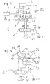
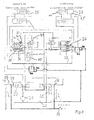
- Figure 1 shows in the form of a substitute or symbolic diagram of the schematic diagram of a hydraulic valve device 1 with a main way valve 2, a multi-way valve switch 3 with inputs A, B, outputs A1, B1 and A2, B2 to a first consumer 7 and a seat valve 4 at the output
- An electrically actuated solenoid valve 8 is used to adjust a control piston 9 in the control housing 10 of the valve 3.
- the multi-way valve switch shows in Figure 1 in the usual representation in the right part of the Symbol is the switching from A, B to A1, B1, in the left part of the switching from A, B to A2, B2, as it is then performed in the middle part accordingly.
- a double-acting main-way valve 2 with two controllable outputs A, B (return line) and one Oil supply from an oil reservoir 20 indicated by a pump 21, the for precise hydraulic actuation and control of consumers, for example, construction machines or the like.
- Such main way valves 2 are expensive. In practice, therefore, these main way valves 2 by a or several cheaper multiway valve 3 supplements.
- 612-way valve switch 3 are two of the Main way valve 2 served inputs A, B, for example, four outputs, namely A1, B1 (return flow) for the first consumer 7 and A2, B2 (Return flow) for the second consumer 6 opposite.
- control for the multi-way valve switch 3 a predetermined position of the Control piston and thus a predetermined pressure of the hydraulic for the 6 causes the same control in effect via an electromagnetic control 13 on the seat valve 4 that this fixed and safely closes and thus a backflow of the hydraulic oil through the leakage the control piston 9 and thus an undesirable adjustment of the control piston 9 definitely prevented.
- two inputs A, B are four outputs opposite, namely an input pair (forward and return line), one with the Main consumers connected pair A1, B1 (forward and return line) and a with the additional consumer 6 connected pair A2, B2 (return line).
- the output pair A2, B2 connected to the additional consumer 6 is preferably only on the output A2 for the forward line with the seat valve. 4 Mistake.
- the seat valve 4 has the advantage that it is tight in the closed position closes and has no Passungsleckage. So close the switch corresponding control in consequence displacement of the piston the way to Additional consumers, so locks the seat valve 4 at the same time this way tight and prevents slow flow of hydraulic oil along the leak. The Adjustment of the consumer 6 remains so long.
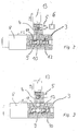
- Figure 2 shows a sectional view of a practically executed 6/2-way valve manifold 3 with a horizontally displaceable within a control housing 10 control piston 9, the control housing 10 in two chambers 11, 12 shares.
- the chamber 11 has two outlets A1, B1 and the chamber 12 has two outlets A2, B2.
- the control piston 9 can be adjusted so that the inputs A, B of the control housing 10 are selectively connected to the outputs A1, B1 or A2, B2.
- the seat valve 4 and thus the hydraulic path 5 to the additional consumer 6 by control 8 and 13 open, so permeable switched.
- Figure 3 shows the sectional view of Figure 2, a 6/2-way valve 3 with seat valve 4, in which the control piston 9 is set so that the inputs A, B connected to the outputs A1, B1 and the hydraulic path 5 to the additional consumer 6 both is closed by the switch 3 and by controlling the seat valve 4.
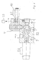
- Figure 4 shows a sectional view through a rapid traverse valve 22 with input A and two outputs FO and FR and built in the output FR seat valve 4.
- the output FR of the seat valve leads to the rod side of a tilting cylinder, not shown, the output FO to the bottom side of this tilting cylinder.
- the control piston 9 of the rapid traverse valve 22 is adjustable so that the input A of the valve 22 is connectable to the output FR and at the same time the seat valve 4 is connected permeable and there is no connection to FO. In this case the rapid traverse function is switched off.
- the bottom-side outlet of the tilting cylinder 23 is directly connected to the outlet of a controlling valve, for example a main directional control valve 2, and guides the hydraulic oil, which subsequently delays piston movement, into the return of this main directional control valve.
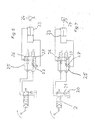
- FIG. 5 shows the symbol representation of a valve device according to FIG. 4.
- the main directional valve 2 with hydraulic reservoir 20 and pump 21 forms the basis of the valve system.
- the output A of the main route valve 2 is not connected here with a switch 3, but with the input A of the rapid traverse valve 22.
- the output FR of this rapid traverse valve 22 is connected to a controllable by a solenoid control valve seat valve 13, whose output to the input FR of the tilt cylinder 23 is connected.
- the input FR of the tilting cylinder 23 is arranged, for example, on the rod side 14 of this cylinder 23.
- An output FO of the tilting cylinder 23 is connected to the output B of the main directional control valve 2, thus directs without rapid traverse the evasive by the displacement of the piston 16 in the tilting cylinder 23 from the bottom side 15 hydraulic oil directly into the return port B of the main directional control valve 2.
- the connection FO of the tilting cylinder on the bottom side 15 of the cylinder 23 is also connected to the terminal FO of the rapid traverse valve 22.
- the rapid traverse valve is so controlled that the displaced hydraulic oil from the input FR to the output FO and to the input FR of the tilting cylinder 23 and there increases the amount of oil.
- the control can also be done so that the displaced oil quantity is not added to the amount of oil supplied, the rapid traverse So put out of order.
- FIG. 6 shows the basic representation of a rapid traverse valve 25 without a displaceable control piston. It includes two poppet valves 26, 27 and a check valve 28.
- the poppet valve 26 is connected at its port A to the corresponding port A of the main directional valve 2.
- the other seat valve 27 is connected with its port B to the corresponding port B of the main route valve 2.
- the other two ports of the poppet valves 26, 27 are connected to each other and to the port FR on the rod side 14 of the tilt cylinder 23.
- the connection FO of the tilting cylinder 23 on its bottom side 15 is connected to the connection B of the main directional control valve 2 facing the connection of the second seat valve 27.
- FIG 7 shows the schematic diagram of the rapid traverse valve 25 shown in Figure 6 with the two seat valves 26, 27 at effectively controlled rapid traverse,
- the seat valve 27 is normally open and the seat valve 26 is closed under power (x-position).
- a check valve 28 at the outlet of the poppet valve 27 indicates that when the poppet valve 27 is open, the oil displaced from the cylinder 23 can only flow or push in the direction of the main directional control valve 2 and, together with the oil coming from the main directional valve, into the bottom side 15 of the cylinder 23 is pressed.
- the rapid traverse valve 25 shown in FIGS. 6 and 7 does not contain a control piston for distributing the hydraulic currents.
- the paths become exclusive steered or deflected by controlling the poppet valves.
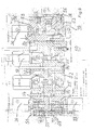
- Figure 8 shows a detailed representation of a hydraulic plan for the control of the rocker 29 for lifting and lowering on the one hand and the implement scoop 24 with scooping and shedding on the other hand.
- the rapid-action valve 25 according to FIGS. 6 and 7 for the bulk curtain is associated with the tilting cylinder 23.
- a parallel guidance of the blade 24 is provided for the loader. This means that the bucket is controlled parallel to the vehicle's longitudinal axis.
- the cylinder 23 for the blade 24 and 17 are executed twice for the rocker 29, each on both sides of the rocker 29.
- the control device of Figure 8 contains the essential for such a parallel guide links the control means for the rocker 29 and the blade 24th ,
- a shut-off valve 40 In the oil path lifting / lowering a shut-off valve 40 is inserted, the for stopping the oil path B-A opens parallel to this shut-off valve 40 is a Load holding valve 41 connected from the line G of the seat valve 36 from is controlled. This valve 41 is therefore in line by the working pressure G is open or closed and allows the raise / lower or lock function this function.
- a pilot operated load holding valve 42 In the oil path between the rod side 14 of the tilt cylinder 23rd via the seat valve 26 to the line C in the oil path exit of the main route valve 34th Scooping / dumping is a pilot operated load holding valve 42 inserted from the second output of the main directional control valve 35 via the line D with possible little pressure is controlled. This is due to the area ratio of the Load holding valve 42 achieved.
- Line D is so in Figure 8 as a control path for the Load holding valve 42 used, and as the oil path F for the cylinder 23.
- the case Pouring effective return from the bottom side 15 of the cylinder 23 is over the Line E and the seat valve 36/37 via the line C in the output of Main way valve 34 connected to the tank 20.
- the oil quantity is controlled by the Poppet valves switched only to raise and lower the swingarm.
- a control of the implement scoop-pouring is not in this case required.
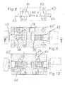
- Figure 9 shows a detailed sectional view of a block 50 for a Control of the movements of the arrangement according to the figures 6, 7 or 8 as well for a hydraulically controlled parallel guidance by using a Combination of poppet valves 36, 37, 38, 26, 27, 43.
- Figure 9 thus shows a prefabricated block with predetermined lines and connections for usable on the one hand controlled and on the other hand the load holding serving poppets and connections to implements.
- This block is a compact, leak-free control device for a front loader with parallel guidance and rapid traverse.
- FIG. 10 shows the schematic diagram of a 6/2 multiport valve switch 60 with two controlled poppet valves 61, 62.
- Each valve 61, 62 is assigned a solenoid valve 63, 64.
- the two seat valves are controlled so that an input 2a to one of two outputs 1 a, 3 a and an input (possibly return) 2 b is switched through to one of two outputs 1 b, 3 b.
- Figure 11 shows a section through a block 65 with the prefabricated therein lines 66 and terminals 1 a, 1 b for the leads for the outer oil path and 68, 69 for the controlled seat valves 61, 62.
- the dimensions of the block and possibly also the control of the poppet valves can be designed so that the thus produced leak-free 6/2-way valve switch with poppet valves, which can replace the usual on the market 6/2-way valve switches with control piston. In this way, previously used switches in case of damage can be easily replaced by the leak-free points.
- Figure 12 shows another section through block 65 shown in Figure 11 (indicated by arrows therein). In FIG. 12, the two outputs 2a, 3a and 2b, 3b are visible.
Landscapes
- Engineering & Computer Science (AREA)
- General Engineering & Computer Science (AREA)
- Physics & Mathematics (AREA)
- Fluid Mechanics (AREA)
- Mechanical Engineering (AREA)
- Mining & Mineral Resources (AREA)
- Civil Engineering (AREA)
- Structural Engineering (AREA)
- Analytical Chemistry (AREA)
- Chemical & Material Sciences (AREA)
- Fluid-Pressure Circuits (AREA)
- Operation Control Of Excavators (AREA)
- Fluid-Driven Valves (AREA)
Abstract
Description
- Figur 1
- eine Prinzipdarstellung einer Steuerkolben-Ventileinrichtung mit Hauptwegeventil, Mehrwegeventilweiche und gesondertem Sitzventil am Ausgang für den Zusatzverbraucher,
- Figur 2
- einen Schnitt durch eine 6/2-Mehrwegeventilweiche mit Steuerkolben und angebautem Sitzventil, bei der der Ölweg zum Zusatzverbraucher durch Ansteuerung offen ist,
- Figur 3
- eine 6/2-Mehrwegeventilweiche gemäß Figur 2, bei der der Ölweg zum Zusatzverbraucher geschlossen ist,
- Figur 4
- ein Eilgangventil mit Steuerkolben und Sitzventil im Ausgang FR,
- Figur 5
- eine Eilgangventileinrichtung mit Sitzventil gemäß Figur 4,
- Figur 6
- eine Eilgangventileinrichtung mit zwei Sitzventilen bei wirksam gesteuertem Eilgang,
- Figur 7
- eine Einrichtung gemäß Figur 6 mit unwirksam gesteuerten Eilgang,
- Figur 8
- eine Steuereinrichtung mit Sitzventilen für Schaufellader mit Schwinge und Schaufel mit Parallelführung und Eilgang,
- Figur 9
- einen Schnitt durch eine blockförmig ausgebildete Anordnung der Steuereinrichtung nach Figur 8,
- Figur 10
- ein 6/2- Wege-Ventil mit zwei Sitzventilen statt Steuerkolben,
- Figur 11, 12
- zwei Schnitte durch ein blockförmig ausgebildetes 6/2-WegeSitzventil nach Figur 10.
Ventile 26, 27 unter Strom ein.
Ventile 36, 37, 43 stromlos ein
Ventile 36, 37, 43 unter Strom aus
- 1
- Ventileinrichtung
- 1 a
- Anschluss in Fig. 11 und 12
- 1 b
- Anschluss in Fig. 11 und 12
- 2
- Hauptwegeventil
- 2a
- Anschluss in Fig. 11 und 12
- 2b
- Anschluss in Fig. 11 und 12
- 3
- Mehrwegeventilweiche
- 3a
- Anschluss in Fig. 11 und 12
- 3b
- Anschluss in Fig. 11 und 12
- 4
- Sitzventil
- 5
- Ausgang von Mehrwegventilweiche 3
- 6
- Zusatzverbraucher
- 7
- erster Verbraucher
- 8
- Magnetventil
- 9
- Steuerkolben
- 10
- Steuergehäuse
- 11
- erste Zylinderkammer
- 12
- zweite Zylinderkammer
- 13
- Steuerung von Sitzventil 4
- 14
- Stangenseite von Kippzylinder 23
- 15
- Bodenseite von Kippzylinder 23
- 16
- Kolben von Kippzylinder 23
- 20
- Ölreservoir
- 21
- Pumpe
- 22
- Eilgangventil in Fig. 4 und 5
- 23
- Kippzylinder
- 24
- Schaufel
- 25
- Eilgangventil in Fig. 6 und 7
- 26
- erstes Sitzventil bei einem Eilgangventil
- 27
- zweites Sitzventil bei einem Eilgangventil
- 28
- Druckventil (Rückschlagventil) an zweitem Sitzventil 27
- 29
- Schwinge
- 30
- Hauptwegeventil Schwinge
- 31
- Magnetventil
- 32
- Schalter Eilgang
- 33
- Schalter Parallelführung
- 34
- Magnetventil Schaufel
- 35
- Hauptwegeventil Schaufel
- 36
- Sitzventil Heben/Senken
- 37
- Sitzventil Heben/Senken
- 38
- Sitzventil Heben/Senken
- 39
- Schalter für Stromzuführung
- 40
- Abstelleinrichtung
- 41
- Lasthalteventil
- 42
- Lasthalteventil
- 43
- Sitzventil im Block 65
- 50
- Block
- 51
- Teilblock
- 52
- Teilblock
- 53
- Teilblock
- 54
- innere Leitungen
- 55
- Anschlüsse
- 56
- Öffnungen
- 57
- Sitzventile Lasthaltung
- 60
- 6/2 Mehrwegventilweiche
- 61
- Sitzventil
- 62
- Sitzventil
- 63
- Magnetventil
- 64
- Magnetventil
- 65
- Block
- 66
- innere Leitungen
- 68
- Anschluss für Sitzventile
- 69
- Anschluss für Sitzventile
- 70, 71
- Sitzventile
- 72, 73
- Sitzventile (von Zündung gesteuert)
- S1
- Schalter für Eilgang bzw. Parallelführung
- S2
- Schalter für Eilgang bzw. Parallelführung
- A
- Eingang zum Hauptwegeventil
- A1
- Ausgang zum ersten Verbraucher
- A2
- Ausgang zum zusätzlichen Verbraucher
- B
- Eingang zum Hauptwegeventil
- B1
- Ausgang zum ersten Verbraucher
- B2
- Ausgang zum zusätzlichen Verbraucher
- FR
- Ausgang für Eilgangventil
- FO
- Ausgang für Eilgangventil
Claims (16)
- Hydraulische Steuereinrichtung mit hydraulisch über einen gesteuerten oder steuerbaren Ölweg (5) betriebene, doppelt wirkende Zylinder (23, 24) aufweisende Frontlader, bei der dem Ein- und/oder Ausgang des Zylinders (23, 24) ein manuell, gesteuert oder automatisch einstellbares Sitzventil (4, 25, 26, 27, 36, 37, 38) so zugeordnet ist, dass der gesteuerte Ölweg (5) durch das oder die Sitzventile (4, 25, 26, 27, 36, 37, 38) willkürlich schließbar und/oder zu öffnen ist,
dadurch gekennzeichnet, dass die Öffnung oder Schließung des Sitzventils (4, 25, 26, 27, 36, 37, 43) im Hydraulikweg (5) zusammen, gleichzeitig und gleichsinnig mit der des Steuerventils (2, 3) erfolgt, wobei die Größe des Hydraulikflusses nur über das Steuerventil (2, 3) bestimmt wird. - Hydraulische Steuereinrichtung (1) nach Anspruch 1,
dadurch gekennzeichnet, dass bei einer Eilgangventileinrichtung jedem der beiden Ausgänge (A2, B2, FO, FR) ein Sitzventil (26, 27) zugeordnet ist. - Hydraulische Steuereinrichtung (1) nach Anspruch 1, 2 oder 3,
dadurch gekennzeichnet, dass das Sitzventil oder die Sitzventile (4, 25, 26, 27, 36, 37, 38) fest mit dem Ausgang oder den Ausgängen (A2, B2) verbunden ist (sind). - Hydraulische Steuereinrichtung nach Anspruch 1, 2, 3 oder 4,
dadurch gekennzeichnet, dass das Sitzventil (4, 25, 26, 27, 36, 37, 38) in den Ausgang (A2) eingeschraubt ist. - Hydraulische Steuereinrichtung (1) nach Anspruch 1, 2, 3, 4 oder 5,
dadurch gekennzeichnet, dass bei einer 6/2-Wegeventilweiche mit einem in einem doppeltwirkenden Steuergehäuse (10) bewegbar angeordneten Steuerkolben (9), der im Steuergehäuse (10) zwei Steuergehäusekammern (11, 12) mit je einem Ausgang (A1, B1, A2, B2) bildet, denen zwei Eingänge (A, B) zugeordnet sind (Hin- und Rückleitung), das mit einem Zusatzverbraucher (6) verbundene Paar (Hin- und Rückleitung A2, B2) nur auf dem Ausgang (A2) für die Hinleitung mit dem Sitzventil (4, 25, 26, 27) versehen ist. - Hydraulische Steuereinrichtung (1) nach einem der Ansprüche 1 bis 5,
dadurch gekennzeichnet, dass von zwei Sitzventilen (26, 27) ein Sitzventil stromlos offen und das andere Sitzventil stromlos geschlossen ist. - Hydraulische Steuereinrichtung (1) nach einem der Ansprüche 1 bis 5,
dadurch gekennzeichnet, dass von zwei Sitzventilen (26, 27) eines unter Strom offen und das andere unter Strom geschlossen ist. - Hydraulische Steuereinrichtung (1) nach einem der Ansprüche 1 bis 7,
dadurch gekennzeichnet, dass beide Sitzventile (41, 42) eine Einheit bilden. - Hydraulische Steuereinrichtung (1) nach einem der Ansprüche 1 bis 8,
dadurch gekennzeichnet, dass die beiden Sitzventile (26, 27) einen gemeinsamen Ein beziehungsweise Ausgang und zwei getrennte Ein beziehungsweise Ausgänge haben. - Hydraulische Steuereinrichtung (1) nach einem der vorstehenden Ansprüche,
dadurch gekennzeichnet, dass das eine Sitzventil stromlos offen und unter Strom geschlossen und das andere Sitzventil stromlos geschlossen und unter Strom offen ist. - Hydraulische Steuereinrichtung (1) nach einem der vorstehenden Ansprüche für die Steuerung eines Werkzeugs (24), insbesondere der Schaufel eines Frontladers oder dergleichen,
dadurch gekennzeichnet, dass zwei Sitzventile (26, 27) mit einem gemeinsamen Ausgang und zwei getrennten Eingängen vorgesehen sind, von denen der eine Eingang mit dem einen Ausgang eines den Öldruck bereitstellenden Hauptwegeventils (2) und der andere Eingang mit dem anderen Ausgang des Hauptwegeventils verbindbar ist,
dass beide Ausgänge Hin- oder Rückleitung bilden,
dass für das Hauptwegeventil (2) Umschaltmittel zur Vertauschung (Schütten, Schöpfen) der Hin- und Rückleitung vorgesehen sind, dass für die beiden Sitzventile eine erste Schaltstellung (0 oder 1) einstellbar ist, in der das eine Sitzventil stromlos offen und das andere Sitzventil stromlos geschlossen ist,
dass für die beiden Sitzventile eine zweite Schaltstellung (1 oder 0) einstellbar ist, in der das eine Sitzventil unter Strom geschlossen und das andere Sitzventil unter Strom offen ist,
dass der gemeinsame Ausgang der beiden Sitzventile mit einer Kammer eines das Werkzeug antreibenden Kippzylinders (23) und der Eingang eines vor den Eingang eines der beiden Sitzventile geschalteten Druckventils (28) mit der anderen Kammer des Kippzylinders (23) verbunden ist, und
dass eine der beiden Schaltstellungen für die Sitzventile dem normalen Schöpf- und Schüttvorgang zugeordnet ist und die andere dem Schüttvorgang im Eilgangbetrieb. - Hydraulische Steuereinrichtung (1) nach einem der Ansprüche 1 bis 10 für die Steuerung der Schwinge (29) eines Frontladers oder dergleichen,
dadurch gekennzeichnet, dass drei Sitzventile (36, 37, 38) vorgesehen sind, von denen das eine (36) mit dem einen Ausgang eines den Öldruck bereitstellenden Hauptwegeventils (2, 30) und das andere (37) mit dem anderen Ausgang des Hauptwegeventils (2, 30) in den Ölweg eingefügt verbindbar ist, dass beide Ausgänge des Hauptwegeventils Hin- oder Rückleitung bilden, dass für das Hauptwegeventil (2, 30) Umschaltmittel (31) zur Vertauschung (Heben, Senken) der Hin- und Rückleitung vorgesehen sind,
dass für die drei Sitzventile (36, 37, 38) eine erste Schaltstellung (0 oder 1) einstellbar ist, in der zwei Sitzventile (36, 37) offen oder geschlossen und das dritte Sitzventil (38) geschlossen oder offen sind,
dass für die drei Sitzventile (36, 37, 38) eine zweite Schaltstellung (1 oder 0) einstellbar ist, in der zwei Sitzventile geschlossen oder offen und das dritte Sitzventil (38) offen oder geschlossen sind,
dass die drei Sitzventile (36, 37, 38) dem mit dem Schwingenzylinder (23) verbundenen Ölweg so zugeordnet sind, dass in der ersten Schaltung (0) die Parallelführung eingeschaltet und in der zweiten Schaltung die Parallelführung ausgeschaltet ist,
dass in beiden Schaltstellungen (0, 1) die Sitzventile (36, 37) der Einstellung Hebevorgang oder Senkvorgang des Hauptwegeventils dienen, und
dass in der zweiten Schaltstellung (1) das dritte Sitzventil (38) die Hinleitung des Ölwegs zum Schwingenzylinder durchschaltet und die Lasthalteventile überbrückt. - Hydraulische Steuereinrichtung (1) nach einem der Ansprüche 1 bis 12,
dadurch gekennzeichnet, dass das Sitzventil (4, 25, 26, 27, 36, 37, 43) im Hydraulikweg (5) zwischen dem Ausgang (A2) eines der Umsteuerung des Ölstroms dienenden Ventils (3), insbesondere einer Mehrwegeventilweiche (3) und einem Verbraucher (6) angeordnet ist, und
dass das Sitzventil (4, 25, 26, 27) zusammen, gleichzeitig und gleichsinnig mit dem Ventil (3) angesteuert wird, insbesondere für diesen Hydraulikweg (5) zusammen mit dem Ventil (3) geschlossen oder geöffnet wird. - Hydraulische Steuereinrichtung (1) nach einem der Ansprüche 1 bis 13,
dadurch gekennzeichnet, dass ein Block mit eingearbeiteten Leitungen und Anschlüssen für Sitzventile vorgesehen ist. - Hydraulische Steuereinrichtung (1) nach einem der Ansprüche 1 bis 14,
dadurch gekennzeichnet, dass ein Block mit eingearbeiteten Leitungen und Anschlüssen für Sitzventile vorgesehen ist, von denen zwei Sitzventile (26, 27) für die Steuerung der Schaufel und drei Sitzventile (36, 37, 38) für die Steuerung der Schwinge vorgesehen sind. - Hydraulische Steuereinrichtung (1) nach einem der Ansprüche 1 bis 15,
dadurch gekennzeichnet, dass in die Ölleitung zwischen den Bodenseiten (15) der Schwingenzylinder (29) und Kippzylinder (23) oder dergleichen und den Anschlüssen F, AF Sitzventile (70, 71) eingefügt sind,
deren Magnete (72, 73) mit der Betriebsbereitschaft (Zündung 39) verbunden sind, wobei
die Sitzventile (70, 71) stromlos (bei ausgeschalteter Zündung 39) geschlossen und bei eingeschalteter Zündung (39) offen sind.
Priority Applications (1)
| Application Number | Priority Date | Filing Date | Title |
|---|---|---|---|
| EP07017554A EP1890044A1 (de) | 2004-04-23 | 2005-04-20 | Hydraulische Steuereinrichtung |
Applications Claiming Priority (2)
| Application Number | Priority Date | Filing Date | Title |
|---|---|---|---|
| DE102004020371 | 2004-04-23 | ||
| DE200410020371 DE102004020371A1 (de) | 2004-04-23 | 2004-04-23 | Hydraulische Steuereinrichtung |
Related Child Applications (1)
| Application Number | Title | Priority Date | Filing Date |
|---|---|---|---|
| EP07017554A Division EP1890044A1 (de) | 2004-04-23 | 2005-04-20 | Hydraulische Steuereinrichtung |
Publications (2)
| Publication Number | Publication Date |
|---|---|
| EP1589232A2 true EP1589232A2 (de) | 2005-10-26 |
| EP1589232A3 EP1589232A3 (de) | 2006-03-29 |
Family
ID=34935420
Family Applications (2)
| Application Number | Title | Priority Date | Filing Date |
|---|---|---|---|
| EP07017554A Withdrawn EP1890044A1 (de) | 2004-04-23 | 2005-04-20 | Hydraulische Steuereinrichtung |
| EP05008582A Withdrawn EP1589232A3 (de) | 2004-04-23 | 2005-04-20 | Hydraulische Steuereinrichtung |
Family Applications Before (1)
| Application Number | Title | Priority Date | Filing Date |
|---|---|---|---|
| EP07017554A Withdrawn EP1890044A1 (de) | 2004-04-23 | 2005-04-20 | Hydraulische Steuereinrichtung |
Country Status (2)
| Country | Link |
|---|---|
| EP (2) | EP1890044A1 (de) |
| DE (1) | DE102004020371A1 (de) |
Cited By (2)
| Publication number | Priority date | Publication date | Assignee | Title |
|---|---|---|---|---|
| CN112010238A (zh) * | 2020-09-28 | 2020-12-01 | 安庆联动属具股份有限公司 | 一种带有液压控制回路系统的快速倾倒翻箱器 |
| CN113970008A (zh) * | 2021-10-16 | 2022-01-25 | 山东锐凯工程机械有限公司 | 一种液压挖掘机用多路阀自动控制方法及系统 |
Families Citing this family (1)
| Publication number | Priority date | Publication date | Assignee | Title |
|---|---|---|---|---|
| EP2837833A3 (de) * | 2013-08-05 | 2015-05-27 | Tries GmbH & CO. KG | Handsteuergeber für eine hydraulische Steuerung |
Family Cites Families (21)
| Publication number | Priority date | Publication date | Assignee | Title |
|---|---|---|---|---|
| DE8416495U1 (de) * | 1984-08-23 | Knopff, Dieter, 3330 Helmstedt | Steuerungsvorrichtung für hydraulische Arbeitsglieder | |
| US2754018A (en) * | 1953-07-13 | 1956-07-10 | Yale & Towne Mfg Co | Hydraulic power lines for industrial truck |
| US3512453A (en) * | 1968-05-22 | 1970-05-19 | Caterpillar Tractor Co | System for actuation of hydraulic motors on tractor powered implements |
| DE2536106A1 (de) * | 1975-08-13 | 1977-02-24 | Hubert Odenthal | Lastabsicherungsventil |
| DE2834480C2 (de) * | 1978-08-05 | 1986-01-02 | Baas Technik GmbH, 2000 Wedel | Steuereinrichtung eines Schaufelladers od.dgl. |
| DE8029716U1 (de) * | 1980-11-07 | 1982-04-15 | Robert Bosch Gmbh, 7000 Stuttgart | Hydraulische Steuereinrichtung für zwei Arbeitszylinder |
| US4359931A (en) * | 1981-01-19 | 1982-11-23 | The Warner & Swasey Company | Regenerative and anticavitation hydraulic system for an excavator |
| DE3705170C1 (de) * | 1987-02-18 | 1988-08-18 | Heilmeier & Weinlein | Hydraulische Steuervorrichtung |
| US5207059A (en) * | 1992-01-15 | 1993-05-04 | Caterpillar Inc. | Hydraulic control system having poppet and spool type valves |
| KR0145143B1 (ko) * | 1992-10-29 | 1998-08-01 | 오까다 하지메 | 유압제어밸브장치 및 유압구동장치 |
| US5331882A (en) * | 1993-04-05 | 1994-07-26 | Deere & Company | Control valve system with float valve |
| DE4436548C2 (de) * | 1994-10-13 | 2000-12-21 | Mannesmann Rexroth Ag | Ventilanordnung zur Betätigung eines hydraulischen Verbrauchers |
| JP3084549B2 (ja) * | 1995-02-16 | 2000-09-04 | 新キャタピラー三菱株式会社 | チルト式ツーウェイドーザの油圧回路 |
| JP3691593B2 (ja) * | 1996-07-05 | 2005-09-07 | 株式会社豊田自動織機 | 荷役用油圧装置 |
| DE29716082U1 (de) * | 1997-09-06 | 1997-11-27 | Hans Sauter GmbH Landtechnik - Stahlbau, 87778 Stetten | 413-Wege-Kugelhahnkombination zum Einbau in die Zuleitung von doppeltwirkenden Zylindern |
| DE19834955B4 (de) * | 1998-08-03 | 2008-02-07 | Linde Material Handling Gmbh | Hydrostatisches Antriebssystem |
| JP3839633B2 (ja) * | 2000-02-07 | 2006-11-01 | 三陽機器株式会社 | 油圧制御装置 |
| DE10006908A1 (de) * | 2000-02-16 | 2001-08-23 | Caterpillar Sarl Genf Geneva | Hydraulische Kolbenzylindereinheit für landwirtschaftliche Arbeitsmaschinen |
| DE10034931B4 (de) * | 2000-07-18 | 2011-03-10 | Linde Material Handling Gmbh | Steuerventileinrichtung |
| DE10150993A1 (de) * | 2001-10-12 | 2003-04-17 | Weidemann Gmbh & Co Kg | Schnellauskippventil |
| JP2005098455A (ja) * | 2003-09-26 | 2005-04-14 | Mitsubishi Heavy Ind Ltd | 産業機械の油圧制御装置 |
-
2004
- 2004-04-23 DE DE200410020371 patent/DE102004020371A1/de not_active Withdrawn
-
2005
- 2005-04-20 EP EP07017554A patent/EP1890044A1/de not_active Withdrawn
- 2005-04-20 EP EP05008582A patent/EP1589232A3/de not_active Withdrawn
Non-Patent Citations (1)
| Title |
|---|
| None * |
Cited By (3)
| Publication number | Priority date | Publication date | Assignee | Title |
|---|---|---|---|---|
| CN112010238A (zh) * | 2020-09-28 | 2020-12-01 | 安庆联动属具股份有限公司 | 一种带有液压控制回路系统的快速倾倒翻箱器 |
| CN113970008A (zh) * | 2021-10-16 | 2022-01-25 | 山东锐凯工程机械有限公司 | 一种液压挖掘机用多路阀自动控制方法及系统 |
| CN113970008B (zh) * | 2021-10-16 | 2024-02-27 | 山东锐凯工程机械有限公司 | 一种液压挖掘机用多路阀自动控制方法及系统 |
Also Published As
| Publication number | Publication date |
|---|---|
| EP1890044A1 (de) | 2008-02-20 |
| DE102004020371A1 (de) | 2005-11-10 |
| EP1589232A3 (de) | 2006-03-29 |
Similar Documents
| Publication | Publication Date | Title |
|---|---|---|
| EP0620371B1 (de) | Hydrauliksystem zur Versorgung offener oder geschlossener Hydraulikfunktionen | |
| DE102007054137A1 (de) | Hydraulische Ventilvorrichtung | |
| DE112020004605T5 (de) | Ein hydrauliksystem für regenerative steuerung | |
| DE69803100T2 (de) | Druckbegrenzungsmechanismus und hydraulischer Schaltkreis mit Druckbegrenzungsmechanismus | |
| DE102007028864A1 (de) | Hydraulische Steueranordnung | |
| DE10310314B4 (de) | Antriebsanordnung, insbesondere Hebevorrichtung eines Arbeitsfahrzeugs | |
| EP1589232A2 (de) | Hydraulische Steuereinrichtung | |
| EP2360380B1 (de) | Hydraulisches Steuerventil für einen einseitig arbeitenden Differentialzylinder mit fünf Steuerkanten | |
| DE102009034286B3 (de) | Hydraulische Schaltungsanordnung zum Steuern eines doppelt wirkenden Arbeitszylinders mittels eine fünf Anschlüsse aufweisenden Steuerventils | |
| DE3534387A1 (de) | Vorgesteuertes 3/2-wegesitzventil | |
| DE2735558C2 (de) | ||
| DE2904293C2 (de) | ||
| DE4030950A1 (de) | Hydraulische steuereinrichtung | |
| DE3431103C2 (de) | ||
| EP1574720A1 (de) | Elektrohydraulische Steuervorrichtung | |
| DE3629471A1 (de) | Hydraulische steuereinrichtung | |
| DE19930101A1 (de) | Schaltvorrichtung für eine Arbeitsmaschine | |
| DE2244445B2 (de) | Hydraulische Einrichtung zum Steuern der Druckmittelwege in einer Anlage mit wenigstens einem doppeltwirkenden Servomotor | |
| DE3731297C1 (de) | Schaltventilanordnung | |
| DE19646425A1 (de) | Ventilanordnung | |
| DE1776176C3 (de) | Hydraulische Steuerventileinrichtung | |
| EP1419910A2 (de) | Hydropneumatische Federung | |
| DE19749639A1 (de) | Hydraulische Schaltung | |
| DE19630798A1 (de) | Vorsteuerung für zwei hydraulisch betätigbare Wegeventile | |
| CH649651A5 (en) | Hydraulic-oil drive device for power circuit breakers |
Legal Events
| Date | Code | Title | Description |
|---|---|---|---|
| PUAI | Public reference made under article 153(3) epc to a published international application that has entered the european phase |
Free format text: ORIGINAL CODE: 0009012 |
|
| AK | Designated contracting states |
Kind code of ref document: A2 Designated state(s): AT BE BG CH CY CZ DE DK EE ES FI FR GB GR HU IE IS IT LI LT LU MC NL PL PT RO SE SI SK TR |
|
| AX | Request for extension of the european patent |
Extension state: AL BA HR LV MK YU |
|
| RIC1 | Information provided on ipc code assigned before grant |
Ipc: 7F 15B 13/00 B Ipc: 7F 15B 11/16 B Ipc: 7F 15B 11/024 B Ipc: 7E 02F 3/65 B Ipc: 7E 02F 9/22 B Ipc: 7F 15B 13/01 B Ipc: 7F 15B 11/00 A |
|
| PUAL | Search report despatched |
Free format text: ORIGINAL CODE: 0009013 |
|
| AK | Designated contracting states |
Kind code of ref document: A3 Designated state(s): AT BE BG CH CY CZ DE DK EE ES FI FR GB GR HU IE IS IT LI LT LU MC NL PL PT RO SE SI SK TR |
|
| AX | Request for extension of the european patent |
Extension state: AL BA HR LV MK YU |
|
| 17P | Request for examination filed |
Effective date: 20060922 |
|
| AKX | Designation fees paid |
Designated state(s): AT BE BG CH CY CZ DE DK EE ES FI FR GB GR HU IE IS IT LI LT LU MC NL PL PT RO SE SI SK TR |
|
| 17Q | First examination report despatched |
Effective date: 20070205 |
|
| STAA | Information on the status of an ep patent application or granted ep patent |
Free format text: STATUS: THE APPLICATION IS DEEMED TO BE WITHDRAWN |
|
| 18D | Application deemed to be withdrawn |
Effective date: 20071101 |