EP1589232A2 - Hydraulic control device - Google Patents
Hydraulic control device Download PDFInfo
- Publication number
- EP1589232A2 EP1589232A2 EP05008582A EP05008582A EP1589232A2 EP 1589232 A2 EP1589232 A2 EP 1589232A2 EP 05008582 A EP05008582 A EP 05008582A EP 05008582 A EP05008582 A EP 05008582A EP 1589232 A2 EP1589232 A2 EP 1589232A2
- Authority
- EP
- European Patent Office
- Prior art keywords
- valve
- seat
- valves
- control device
- hydraulic control
- Prior art date
- Legal status (The legal status is an assumption and is not a legal conclusion. Google has not performed a legal analysis and makes no representation as to the accuracy of the status listed.)
- Withdrawn
Links
- 230000001007 puffing effect Effects 0.000 claims 1
- 239000003921 oil Substances 0.000 description 42
- 239000010720 hydraulic oil Substances 0.000 description 24
- RZVAJINKPMORJF-UHFFFAOYSA-N Acetaminophen Chemical class CC(=O)NC1=CC=C(O)C=C1 RZVAJINKPMORJF-UHFFFAOYSA-N 0.000 description 10
- 238000010586 diagram Methods 0.000 description 4
- 238000006073 displacement reaction Methods 0.000 description 4
- 238000010276 construction Methods 0.000 description 3
- 230000005611 electricity Effects 0.000 description 3
- 230000008901 benefit Effects 0.000 description 2
- 230000000903 blocking effect Effects 0.000 description 2
- 230000008859 change Effects 0.000 description 2
- 238000011161 development Methods 0.000 description 2
- 230000018109 developmental process Effects 0.000 description 2
- 230000000694 effects Effects 0.000 description 2
- 238000004519 manufacturing process Methods 0.000 description 2
- 230000004913 activation Effects 0.000 description 1
- 230000001934 delay Effects 0.000 description 1
- 230000001419 dependent effect Effects 0.000 description 1
- 230000000994 depressogenic effect Effects 0.000 description 1
- 238000005516 engineering process Methods 0.000 description 1
- 238000000034 method Methods 0.000 description 1
- 230000008569 process Effects 0.000 description 1
- 239000013589 supplement Substances 0.000 description 1
Images
Classifications
-
- E—FIXED CONSTRUCTIONS
- E02—HYDRAULIC ENGINEERING; FOUNDATIONS; SOIL SHIFTING
- E02F—DREDGING; SOIL-SHIFTING
- E02F9/00—Component parts of dredgers or soil-shifting machines, not restricted to one of the kinds covered by groups E02F3/00 - E02F7/00
- E02F9/20—Drives; Control devices
- E02F9/22—Hydraulic or pneumatic drives
- E02F9/2264—Arrangements or adaptations of elements for hydraulic drives
- E02F9/2267—Valves or distributors
-
- E—FIXED CONSTRUCTIONS
- E02—HYDRAULIC ENGINEERING; FOUNDATIONS; SOIL SHIFTING
- E02F—DREDGING; SOIL-SHIFTING
- E02F9/00—Component parts of dredgers or soil-shifting machines, not restricted to one of the kinds covered by groups E02F3/00 - E02F7/00
- E02F9/20—Drives; Control devices
- E02F9/22—Hydraulic or pneumatic drives
- E02F9/226—Safety arrangements, e.g. hydraulic driven fans, preventing cavitation, leakage, overheating
-
- E—FIXED CONSTRUCTIONS
- E02—HYDRAULIC ENGINEERING; FOUNDATIONS; SOIL SHIFTING
- E02F—DREDGING; SOIL-SHIFTING
- E02F9/00—Component parts of dredgers or soil-shifting machines, not restricted to one of the kinds covered by groups E02F3/00 - E02F7/00
- E02F9/20—Drives; Control devices
- E02F9/22—Hydraulic or pneumatic drives
- E02F9/2264—Arrangements or adaptations of elements for hydraulic drives
- E02F9/2271—Actuators and supports therefor and protection therefor
-
- F—MECHANICAL ENGINEERING; LIGHTING; HEATING; WEAPONS; BLASTING
- F15—FLUID-PRESSURE ACTUATORS; HYDRAULICS OR PNEUMATICS IN GENERAL
- F15B—SYSTEMS ACTING BY MEANS OF FLUIDS IN GENERAL; FLUID-PRESSURE ACTUATORS, e.g. SERVOMOTORS; DETAILS OF FLUID-PRESSURE SYSTEMS, NOT OTHERWISE PROVIDED FOR
- F15B11/00—Servomotor systems without provision for follow-up action; Circuits therefor
- F15B11/003—Systems with load-holding valves
-
- F—MECHANICAL ENGINEERING; LIGHTING; HEATING; WEAPONS; BLASTING
- F15—FLUID-PRESSURE ACTUATORS; HYDRAULICS OR PNEUMATICS IN GENERAL
- F15B—SYSTEMS ACTING BY MEANS OF FLUIDS IN GENERAL; FLUID-PRESSURE ACTUATORS, e.g. SERVOMOTORS; DETAILS OF FLUID-PRESSURE SYSTEMS, NOT OTHERWISE PROVIDED FOR
- F15B11/00—Servomotor systems without provision for follow-up action; Circuits therefor
- F15B11/02—Systems essentially incorporating special features for controlling the speed or actuating force of an output member
- F15B11/024—Systems essentially incorporating special features for controlling the speed or actuating force of an output member by means of differential connection of the servomotor lines, e.g. regenerative circuits
-
- F—MECHANICAL ENGINEERING; LIGHTING; HEATING; WEAPONS; BLASTING
- F15—FLUID-PRESSURE ACTUATORS; HYDRAULICS OR PNEUMATICS IN GENERAL
- F15B—SYSTEMS ACTING BY MEANS OF FLUIDS IN GENERAL; FLUID-PRESSURE ACTUATORS, e.g. SERVOMOTORS; DETAILS OF FLUID-PRESSURE SYSTEMS, NOT OTHERWISE PROVIDED FOR
- F15B20/00—Safety arrangements for fluid actuator systems; Applications of safety devices in fluid actuator systems; Emergency measures for fluid actuator systems
- F15B20/005—Leakage; Spillage; Hose burst
-
- F—MECHANICAL ENGINEERING; LIGHTING; HEATING; WEAPONS; BLASTING
- F15—FLUID-PRESSURE ACTUATORS; HYDRAULICS OR PNEUMATICS IN GENERAL
- F15B—SYSTEMS ACTING BY MEANS OF FLUIDS IN GENERAL; FLUID-PRESSURE ACTUATORS, e.g. SERVOMOTORS; DETAILS OF FLUID-PRESSURE SYSTEMS, NOT OTHERWISE PROVIDED FOR
- F15B2211/00—Circuits for servomotor systems
- F15B2211/30—Directional control
- F15B2211/305—Directional control characterised by the type of valves
- F15B2211/30525—Directional control valves, e.g. 4/3-directional control valve
-
- F—MECHANICAL ENGINEERING; LIGHTING; HEATING; WEAPONS; BLASTING
- F15—FLUID-PRESSURE ACTUATORS; HYDRAULICS OR PNEUMATICS IN GENERAL
- F15B—SYSTEMS ACTING BY MEANS OF FLUIDS IN GENERAL; FLUID-PRESSURE ACTUATORS, e.g. SERVOMOTORS; DETAILS OF FLUID-PRESSURE SYSTEMS, NOT OTHERWISE PROVIDED FOR
- F15B2211/00—Circuits for servomotor systems
- F15B2211/30—Directional control
- F15B2211/305—Directional control characterised by the type of valves
- F15B2211/3056—Assemblies of multiple valves
- F15B2211/30565—Assemblies of multiple valves having multiple valves for a single output member, e.g. for creating higher valve function by use of multiple valves like two 2/2-valves replacing a 5/3-valve
- F15B2211/3058—Assemblies of multiple valves having multiple valves for a single output member, e.g. for creating higher valve function by use of multiple valves like two 2/2-valves replacing a 5/3-valve having additional valves for interconnecting the fluid chambers of a double-acting actuator, e.g. for regeneration mode or for floating mode
-
- F—MECHANICAL ENGINEERING; LIGHTING; HEATING; WEAPONS; BLASTING
- F15—FLUID-PRESSURE ACTUATORS; HYDRAULICS OR PNEUMATICS IN GENERAL
- F15B—SYSTEMS ACTING BY MEANS OF FLUIDS IN GENERAL; FLUID-PRESSURE ACTUATORS, e.g. SERVOMOTORS; DETAILS OF FLUID-PRESSURE SYSTEMS, NOT OTHERWISE PROVIDED FOR
- F15B2211/00—Circuits for servomotor systems
- F15B2211/30—Directional control
- F15B2211/31—Directional control characterised by the positions of the valve element
- F15B2211/3105—Neutral or centre positions
- F15B2211/3116—Neutral or centre positions the pump port being open in the centre position, e.g. so-called open centre
-
- F—MECHANICAL ENGINEERING; LIGHTING; HEATING; WEAPONS; BLASTING
- F15—FLUID-PRESSURE ACTUATORS; HYDRAULICS OR PNEUMATICS IN GENERAL
- F15B—SYSTEMS ACTING BY MEANS OF FLUIDS IN GENERAL; FLUID-PRESSURE ACTUATORS, e.g. SERVOMOTORS; DETAILS OF FLUID-PRESSURE SYSTEMS, NOT OTHERWISE PROVIDED FOR
- F15B2211/00—Circuits for servomotor systems
- F15B2211/30—Directional control
- F15B2211/315—Directional control characterised by the connections of the valve or valves in the circuit
- F15B2211/3157—Directional control characterised by the connections of the valve or valves in the circuit being connected to a pressure source, an output member and a return line
- F15B2211/31576—Directional control characterised by the connections of the valve or valves in the circuit being connected to a pressure source, an output member and a return line having a single pressure source and a single output member
-
- F—MECHANICAL ENGINEERING; LIGHTING; HEATING; WEAPONS; BLASTING
- F15—FLUID-PRESSURE ACTUATORS; HYDRAULICS OR PNEUMATICS IN GENERAL
- F15B—SYSTEMS ACTING BY MEANS OF FLUIDS IN GENERAL; FLUID-PRESSURE ACTUATORS, e.g. SERVOMOTORS; DETAILS OF FLUID-PRESSURE SYSTEMS, NOT OTHERWISE PROVIDED FOR
- F15B2211/00—Circuits for servomotor systems
- F15B2211/30—Directional control
- F15B2211/32—Directional control characterised by the type of actuation
- F15B2211/321—Directional control characterised by the type of actuation mechanically
- F15B2211/324—Directional control characterised by the type of actuation mechanically manually, e.g. by using a lever or pedal
-
- F—MECHANICAL ENGINEERING; LIGHTING; HEATING; WEAPONS; BLASTING
- F15—FLUID-PRESSURE ACTUATORS; HYDRAULICS OR PNEUMATICS IN GENERAL
- F15B—SYSTEMS ACTING BY MEANS OF FLUIDS IN GENERAL; FLUID-PRESSURE ACTUATORS, e.g. SERVOMOTORS; DETAILS OF FLUID-PRESSURE SYSTEMS, NOT OTHERWISE PROVIDED FOR
- F15B2211/00—Circuits for servomotor systems
- F15B2211/70—Output members, e.g. hydraulic motors or cylinders or control therefor
- F15B2211/71—Multiple output members, e.g. multiple hydraulic motors or cylinders
- F15B2211/7114—Multiple output members, e.g. multiple hydraulic motors or cylinders with direct connection between the chambers of different actuators
- F15B2211/7128—Multiple output members, e.g. multiple hydraulic motors or cylinders with direct connection between the chambers of different actuators the chambers being connected in parallel
-
- F—MECHANICAL ENGINEERING; LIGHTING; HEATING; WEAPONS; BLASTING
- F15—FLUID-PRESSURE ACTUATORS; HYDRAULICS OR PNEUMATICS IN GENERAL
- F15B—SYSTEMS ACTING BY MEANS OF FLUIDS IN GENERAL; FLUID-PRESSURE ACTUATORS, e.g. SERVOMOTORS; DETAILS OF FLUID-PRESSURE SYSTEMS, NOT OTHERWISE PROVIDED FOR
- F15B2211/00—Circuits for servomotor systems
- F15B2211/70—Output members, e.g. hydraulic motors or cylinders or control therefor
- F15B2211/71—Multiple output members, e.g. multiple hydraulic motors or cylinders
- F15B2211/7142—Multiple output members, e.g. multiple hydraulic motors or cylinders the output members being arranged in multiple groups
Definitions
- the invention relates to a hydraulic control device for hydraulically over a controlled or controllable oil path operated, double-acting cylinder having front loader.
- Front loaders are known to contain boom like Oscillators or telescopes and portable work tools of various kinds Versions.
- Such hydraulic valve devices are, for example, in Plant construction, used in the construction and agricultural machinery hydraulics.
- double-acting valves serve to control the flow direction of the Hydraulic oil for adjustment or adjustment of connected devices in To control both directions and on the other hand, the flow of hydraulic oil make multiple devices or device parts distributable.
- main way valve by additional hydraulic switches be supplemented, for example, the commonly used, so-called 6/2-way valve turnouts.
- 6/2-way valve turnouts With a double-acting main way valve and one or several double-acting hydraulic switches in the manner of the 6/2 way valve is it possible to have a convenient pre-selection control for almost anything to create many consumers.
- electric lifting magnet or one manual control of valves in sliding piston design, below Called control piston many settings can be direct, automatic or in Area code to be made.
- a spool in main directional valves or multipath valve switches already has at first use an unavoidable Passungsleckage. It has showed that the fit leakage increases with age.
- the hydraulic oil flows in de-energized Position of the electromagnetic control to the main consumer with the usual initial designation A1 or B1. Will the switch activated, the hydraulic oil flows to the additional consumer (outputs A2, B2 Return line). So that the hydraulic oil in multiway valves always to the selected outlet flows, the spool must always be correctly positioned. Even a slight leakage on the control piston in the control housing or in Multiway valve worsens this correct positioning. That could do it lead that in a parked with a raised rocker front loader the Swing slowly slowly from the high altitude into a low altitude overnight. Under the swingarm arranged objects like other vehicles could then be damaged.
- a leakage between the spool and the control housing for a Tilting cylinder also has an unfavorable effect on functional processes in connection with so-called rapid traverse valves.
- Rapid valves used to automatically or on electrical command through the Piston movement of the tilt cylinder on the rod side evasive Do not give amounts of oil in the return, but the amount of pump on the Add bottom side. In practical operation tilts the tilting cylinder the shovel he operated faster. A leak would be here Slow down the desired express function again.
- the known device uses a proportional control and Proportional valves by means of a microprocessor system to the hydraulic flow to control the timing and size of the hydraulic flow.
- the invention is based on the object, the influence of leaks in Hydraulic valve devices without the use of complicated microprocessor circuits to avoid. This object is defined by the in claim 1 Invention solved. Further developments of the invention are in the dependent Claims marked.
- the invention consists in a hydraulic control device for a or more, hydraulically via a controlled or controllable oil path operated, double-acting cylinder having jib and working tools like lifting rockers and tilting devices in that into the oil path or more, manually, controlled or automatically by electrically controlled Solenoid valves actuated poppet valves (4, 25, 26, 27) are inserted, the each activated simultaneously and in the same direction with the cylinder become.
- the thrust piston can not change its position in the cylinder, if only one of the two separated or formed by the thrust piston cylinder chambers is completely sealed for the passage of hydraulic oil. A such perfect locking can be achieved by a controlled seat valve become.
- a double-acting hydraulic valve device with one in one Control housing movably arranged control piston and with two by the Control piston separate control housing chambers, in each of which an input for hydraulic oil with one of two outputs to the implement and an outlet for the return of the hydraulic oil with one of two inputs is connectable to the working device for this return, should at least in an output to the implement a controlled activatable seat valve inserted be.
- Control piston and seat valve are controlled so that at a Oil path opening control piston and the seat valve is open. Will the Controlled control piston in a position blocking the oil path, is also the Seat valve locked. This ensures that the control piston even with a more or less large leakage in connection with the precise blocking the poppet valve can fulfill its control function.
- the poppet valve is in the hydraulic path between the Output of the multi-way valve switch and the additional consumer arranged.
- This seat valve is used together with the control piston of the Multi-way valve switch controlled, especially for this hydraulic path closed together with the corresponding path through the switch or open.
- the poppet valve is in the outlet of the multi-way valve switch screwed in, so firmly connected to this switch.
- At a 6/2-way valve switch are two inputs for the hydraulic oil (out and Return flow) from the oil reservoir or from the main directional valve switch four outlets opposite, namely a pair connected to the main consumer (outward and forward Return line) and a pair connected to the additional consumer (outward and forward Return).
- the associated with the additional consumer output pair is preferably only provided on the output for the forward line with the seat valve.
- the seat valve has the advantage that it closes tightly in the closed position and no Passungsleckage has. So close the switch by appropriate Activation in sequence Displacement of the control piston the way to Additional consumers, so at the same time locks the seat valve this way tight and thus prevents a slow backflow of the hydraulic oil along the passage.
- a tilt cylinder In a tilt cylinder is the main way valve or another the Tilting cylinder controlling valve controlled so that in one position an output with the rod side of the tilt cylinder and the other outlet with the bottom side connected is. Thereby, the operated by the tilt cylinder blade is in a moved predetermined position. In the other position of the main way valve the two outputs are interchanged and the bucket in accordingly moves the opposite position.
- the rapid traverse valve is inserted. In this rapid-action valve are evasive oil quantities instead of the piston movement in the tilt cylinder Return immediately added to the pump quantity.
- a seat valve Between the Rapid valve and the tilt cylinder is inserted a seat valve. As soon as the Movement of the thrust piston stops in the tilt cylinder, for example by the Control is stopped, the seat valve is closed and a leakage return prevented.
- the rapid traverse valve is the Rapid valve provided with two seat valves.
- a control piston in the rapid-action valve can be omitted.
- One of the seat valves is open when no electricity is flowing and closed when electricity is flowing.
- the other seat valve is open when power is on flows and closes when no current flows. Since in this case always one Cylinder chamber of the tilt cylinder is hermetically closed, the remains Push piston and thus the implement in position.
- At rapid traverse expresses that displaced oil directly through the seat valve or a valve that opens in case of overpressure in the oil flow coming from the controlling valve, such as the main directional control valve to the tilt valve, so adds the amount of both lines.
- the thrust piston can be omitted and controlled by two Poppet valves are replaced.
- These seat valves for example, connect without Power supply the respective input or output, each with a connection and with power supply, each with a different connection.
- Such a 6/2-way seat valve comes with a block of paths and connections and connections for the interchangeable seat valves formed.
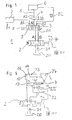
- Figure 1 shows in the form of a substitute or symbolic diagram of the schematic diagram of a hydraulic valve device 1 with a main way valve 2, a multi-way valve switch 3 with inputs A, B, outputs A1, B1 and A2, B2 to a first consumer 7 and a seat valve 4 at the output
- An electrically actuated solenoid valve 8 is used to adjust a control piston 9 in the control housing 10 of the valve 3.
- the multi-way valve switch shows in Figure 1 in the usual representation in the right part of the Symbol is the switching from A, B to A1, B1, in the left part of the switching from A, B to A2, B2, as it is then performed in the middle part accordingly.
- a double-acting main-way valve 2 with two controllable outputs A, B (return line) and one Oil supply from an oil reservoir 20 indicated by a pump 21, the for precise hydraulic actuation and control of consumers, for example, construction machines or the like.
- Such main way valves 2 are expensive. In practice, therefore, these main way valves 2 by a or several cheaper multiway valve 3 supplements.
- 612-way valve switch 3 are two of the Main way valve 2 served inputs A, B, for example, four outputs, namely A1, B1 (return flow) for the first consumer 7 and A2, B2 (Return flow) for the second consumer 6 opposite.
- control for the multi-way valve switch 3 a predetermined position of the Control piston and thus a predetermined pressure of the hydraulic for the 6 causes the same control in effect via an electromagnetic control 13 on the seat valve 4 that this fixed and safely closes and thus a backflow of the hydraulic oil through the leakage the control piston 9 and thus an undesirable adjustment of the control piston 9 definitely prevented.
- two inputs A, B are four outputs opposite, namely an input pair (forward and return line), one with the Main consumers connected pair A1, B1 (forward and return line) and a with the additional consumer 6 connected pair A2, B2 (return line).
- the output pair A2, B2 connected to the additional consumer 6 is preferably only on the output A2 for the forward line with the seat valve. 4 Mistake.
- the seat valve 4 has the advantage that it is tight in the closed position closes and has no Passungsleckage. So close the switch corresponding control in consequence displacement of the piston the way to Additional consumers, so locks the seat valve 4 at the same time this way tight and prevents slow flow of hydraulic oil along the leak. The Adjustment of the consumer 6 remains so long.
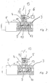
- Figure 2 shows a sectional view of a practically executed 6/2-way valve manifold 3 with a horizontally displaceable within a control housing 10 control piston 9, the control housing 10 in two chambers 11, 12 shares.
- the chamber 11 has two outlets A1, B1 and the chamber 12 has two outlets A2, B2.
- the control piston 9 can be adjusted so that the inputs A, B of the control housing 10 are selectively connected to the outputs A1, B1 or A2, B2.
- the seat valve 4 and thus the hydraulic path 5 to the additional consumer 6 by control 8 and 13 open, so permeable switched.
- Figure 3 shows the sectional view of Figure 2, a 6/2-way valve 3 with seat valve 4, in which the control piston 9 is set so that the inputs A, B connected to the outputs A1, B1 and the hydraulic path 5 to the additional consumer 6 both is closed by the switch 3 and by controlling the seat valve 4.
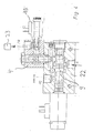
- Figure 4 shows a sectional view through a rapid traverse valve 22 with input A and two outputs FO and FR and built in the output FR seat valve 4.
- the output FR of the seat valve leads to the rod side of a tilting cylinder, not shown, the output FO to the bottom side of this tilting cylinder.
- the control piston 9 of the rapid traverse valve 22 is adjustable so that the input A of the valve 22 is connectable to the output FR and at the same time the seat valve 4 is connected permeable and there is no connection to FO. In this case the rapid traverse function is switched off.
- the bottom-side outlet of the tilting cylinder 23 is directly connected to the outlet of a controlling valve, for example a main directional control valve 2, and guides the hydraulic oil, which subsequently delays piston movement, into the return of this main directional control valve.
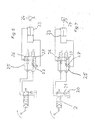
- FIG. 5 shows the symbol representation of a valve device according to FIG. 4.
- the main directional valve 2 with hydraulic reservoir 20 and pump 21 forms the basis of the valve system.
- the output A of the main route valve 2 is not connected here with a switch 3, but with the input A of the rapid traverse valve 22.
- the output FR of this rapid traverse valve 22 is connected to a controllable by a solenoid control valve seat valve 13, whose output to the input FR of the tilt cylinder 23 is connected.
- the input FR of the tilting cylinder 23 is arranged, for example, on the rod side 14 of this cylinder 23.
- An output FO of the tilting cylinder 23 is connected to the output B of the main directional control valve 2, thus directs without rapid traverse the evasive by the displacement of the piston 16 in the tilting cylinder 23 from the bottom side 15 hydraulic oil directly into the return port B of the main directional control valve 2.
- the connection FO of the tilting cylinder on the bottom side 15 of the cylinder 23 is also connected to the terminal FO of the rapid traverse valve 22.
- the rapid traverse valve is so controlled that the displaced hydraulic oil from the input FR to the output FO and to the input FR of the tilting cylinder 23 and there increases the amount of oil.
- the control can also be done so that the displaced oil quantity is not added to the amount of oil supplied, the rapid traverse So put out of order.
- FIG. 6 shows the basic representation of a rapid traverse valve 25 without a displaceable control piston. It includes two poppet valves 26, 27 and a check valve 28.
- the poppet valve 26 is connected at its port A to the corresponding port A of the main directional valve 2.
- the other seat valve 27 is connected with its port B to the corresponding port B of the main route valve 2.
- the other two ports of the poppet valves 26, 27 are connected to each other and to the port FR on the rod side 14 of the tilt cylinder 23.
- the connection FO of the tilting cylinder 23 on its bottom side 15 is connected to the connection B of the main directional control valve 2 facing the connection of the second seat valve 27.
- FIG 7 shows the schematic diagram of the rapid traverse valve 25 shown in Figure 6 with the two seat valves 26, 27 at effectively controlled rapid traverse,
- the seat valve 27 is normally open and the seat valve 26 is closed under power (x-position).
- a check valve 28 at the outlet of the poppet valve 27 indicates that when the poppet valve 27 is open, the oil displaced from the cylinder 23 can only flow or push in the direction of the main directional control valve 2 and, together with the oil coming from the main directional valve, into the bottom side 15 of the cylinder 23 is pressed.
- the rapid traverse valve 25 shown in FIGS. 6 and 7 does not contain a control piston for distributing the hydraulic currents.
- the paths become exclusive steered or deflected by controlling the poppet valves.
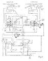
- Figure 8 shows a detailed representation of a hydraulic plan for the control of the rocker 29 for lifting and lowering on the one hand and the implement scoop 24 with scooping and shedding on the other hand.
- the rapid-action valve 25 according to FIGS. 6 and 7 for the bulk curtain is associated with the tilting cylinder 23.
- a parallel guidance of the blade 24 is provided for the loader. This means that the bucket is controlled parallel to the vehicle's longitudinal axis.
- the cylinder 23 for the blade 24 and 17 are executed twice for the rocker 29, each on both sides of the rocker 29.
- the control device of Figure 8 contains the essential for such a parallel guide links the control means for the rocker 29 and the blade 24th ,
- a shut-off valve 40 In the oil path lifting / lowering a shut-off valve 40 is inserted, the for stopping the oil path B-A opens parallel to this shut-off valve 40 is a Load holding valve 41 connected from the line G of the seat valve 36 from is controlled. This valve 41 is therefore in line by the working pressure G is open or closed and allows the raise / lower or lock function this function.
- a pilot operated load holding valve 42 In the oil path between the rod side 14 of the tilt cylinder 23rd via the seat valve 26 to the line C in the oil path exit of the main route valve 34th Scooping / dumping is a pilot operated load holding valve 42 inserted from the second output of the main directional control valve 35 via the line D with possible little pressure is controlled. This is due to the area ratio of the Load holding valve 42 achieved.
- Line D is so in Figure 8 as a control path for the Load holding valve 42 used, and as the oil path F for the cylinder 23.
- the case Pouring effective return from the bottom side 15 of the cylinder 23 is over the Line E and the seat valve 36/37 via the line C in the output of Main way valve 34 connected to the tank 20.
- the oil quantity is controlled by the Poppet valves switched only to raise and lower the swingarm.
- a control of the implement scoop-pouring is not in this case required.
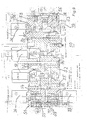
- Figure 9 shows a detailed sectional view of a block 50 for a Control of the movements of the arrangement according to the figures 6, 7 or 8 as well for a hydraulically controlled parallel guidance by using a Combination of poppet valves 36, 37, 38, 26, 27, 43.
- Figure 9 thus shows a prefabricated block with predetermined lines and connections for usable on the one hand controlled and on the other hand the load holding serving poppets and connections to implements.
- This block is a compact, leak-free control device for a front loader with parallel guidance and rapid traverse.
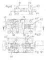
- FIG. 10 shows the schematic diagram of a 6/2 multiport valve switch 60 with two controlled poppet valves 61, 62.
- Each valve 61, 62 is assigned a solenoid valve 63, 64.
- the two seat valves are controlled so that an input 2a to one of two outputs 1 a, 3 a and an input (possibly return) 2 b is switched through to one of two outputs 1 b, 3 b.
- Figure 11 shows a section through a block 65 with the prefabricated therein lines 66 and terminals 1 a, 1 b for the leads for the outer oil path and 68, 69 for the controlled seat valves 61, 62.
- the dimensions of the block and possibly also the control of the poppet valves can be designed so that the thus produced leak-free 6/2-way valve switch with poppet valves, which can replace the usual on the market 6/2-way valve switches with control piston. In this way, previously used switches in case of damage can be easily replaced by the leak-free points.
- Figure 12 shows another section through block 65 shown in Figure 11 (indicated by arrows therein). In FIG. 12, the two outputs 2a, 3a and 2b, 3b are visible.
Landscapes
- Engineering & Computer Science (AREA)
- General Engineering & Computer Science (AREA)
- Civil Engineering (AREA)
- Mechanical Engineering (AREA)
- Fluid Mechanics (AREA)
- Mining & Mineral Resources (AREA)
- Physics & Mathematics (AREA)
- Structural Engineering (AREA)
- Chemical & Material Sciences (AREA)
- Analytical Chemistry (AREA)
- Fluid-Pressure Circuits (AREA)
- Operation Control Of Excavators (AREA)
- Fluid-Driven Valves (AREA)
Abstract
Description
Die Erfindung betrifft eine Hydraulische Steuereinrichtung für hydraulisch über einen gesteuerten oder steuerbaren Ölweg betriebene, doppelt wirkende Zylinder aufweisende Frontlader. Frontlader enthalten bekanntlich Ausleger wie Schwinger oder Teleskope und bewegliche Arbeitswerkzeuge verschiedener Ausführungen. Solche Hydraulik- Ventileinrichtungen werden beispielsweise im Anlagenbau, bei der Bau- und Landmaschinenhydraulik verwendet.The invention relates to a hydraulic control device for hydraulically over a controlled or controllable oil path operated, double-acting cylinder having front loader. Front loaders are known to contain boom like Oscillators or telescopes and portable work tools of various kinds Versions. Such hydraulic valve devices are, for example, in Plant construction, used in the construction and agricultural machinery hydraulics.
Es ist bekannt (DE 28 34 480 C2), Schiebekolben von Kipp- und/oder
Hubzylindern über doppeltwirkende Haupt- oder Mehrwegeventile zu steuern,
denen das Hydrauliköl aus einem Behälter über Pumpen zugeführt wird und bei
denen ein Rücklauf des Hydrauliköls zu diesem Behälter vorgesehen ist. Durch
steuerbare Hubmagnete sind Schiebekolben in diesen Ventilen so verschiebbar,
dass das Hydrauliköl einem der beiden Eingänge der Zylinder zugeführt wird,
wobei der jeweils andere Eingang zum Ausgang für das durch die Bewegung
des Schiebekolbens verdrängte Hydrauliköl gemacht wird. Das verdrängte
Hydrauliköl wird beispielsweise dem Rücklauf zugeführt.It is known (
Doppeltwirkende Ventile dienen einerseits dazu, die Flussrichtung des Hydrauliköls zur Einstellung oder Verstellung von angeschlossenen Geräten in beiden Richtungen zu steuern und andrerseits, den Fluss des Hydrauliköls auf mehrere Geräte oder Geräteteile verteilbar zu gestalten. Zu diesem Zweck kann ein sogenanntes Hauptwegeventil durch zusätzliche hydraulische Weichen ergänzt werden, beispielsweise die häufig verwendeten, sogenannten 6/2-Wegeventilweichen. Mit einem doppeltwirkenden Hauptwegeventil und ein oder mehreren doppeltwirkenden hydraulischen Weichen nach Art des 6/2-Wegeventils ist es möglich, eine bequeme Vorwahlsteuerung für fast beliebig viele Verbraucher zu schaffen. Mit elektrischen Hubmagneten oder einer manuellen Steuerung von Ventilen in Schiebekolbenausführung, im Folgenden Steuerkolben genannt, können viele Einstellungen direkt, automatisch oder in Vorwahl getätigt werden. On the one hand, double-acting valves serve to control the flow direction of the Hydraulic oil for adjustment or adjustment of connected devices in To control both directions and on the other hand, the flow of hydraulic oil make multiple devices or device parts distributable. For this purpose can a so-called main way valve by additional hydraulic switches be supplemented, for example, the commonly used, so-called 6/2-way valve turnouts. With a double-acting main way valve and one or several double-acting hydraulic switches in the manner of the 6/2 way valve is it possible to have a convenient pre-selection control for almost anything to create many consumers. With electric lifting magnet or one manual control of valves in sliding piston design, below Called control piston, many settings can be direct, automatic or in Area code to be made.
Ein Steuerkolben in Hauptwegeventilen oder Mehrwegeventilweichen hat bereits bei erstmaliger Benutzung eine nicht vermeidbare Passungsleckage. Es hat sich gezeigt, dass sich die Passungsleckage mit zunehmendem Alter steigert. Bei einem 6/2-Wegeventil mit Steuerkolben fließt das Hydrauliköl in stromloser Stellung der elektromagnetischen Steuerung zum Hauptverbraucher mit der üblichen Ausgangsbezeichnung A1 beziehungsweise B1. Wird die Weiche aktiviert, fließt das Hydrauliköl zum zusätzlichen Verbraucher (Ausgänge A2, B2 Hin- und Rückleitung). Damit das Hydrauliköl bei Mehrwegeventilen immer zum gewählten Ausgang fließt, muss der Steuerkolben stets richtig positioniert sein. Eine auch nur geringe Leckage am Steuerkolben im Steuergehäuse oder im Mehrwegeventil verschlechtert diese richtige Positionierung. Das könnte dazu führen, dass bei einem mit hochgestellter Schwinge abgestellten Frontlader die Schwinge über Nacht langsam von der Hochlage in eine Tieflage absinkt. Unter der Schwinge angeordnete Gegenstände wie andere Fahrzeuge könnten dann beschädigt sein.A spool in main directional valves or multipath valve switches already has at first use an unavoidable Passungsleckage. It has showed that the fit leakage increases with age. at a 6/2-way valve with control piston, the hydraulic oil flows in de-energized Position of the electromagnetic control to the main consumer with the usual initial designation A1 or B1. Will the switch activated, the hydraulic oil flows to the additional consumer (outputs A2, B2 Return line). So that the hydraulic oil in multiway valves always to the selected outlet flows, the spool must always be correctly positioned. Even a slight leakage on the control piston in the control housing or in Multiway valve worsens this correct positioning. That could do it lead that in a parked with a raised rocker front loader the Swing slowly slowly from the high altitude into a low altitude overnight. Under the swingarm arranged objects like other vehicles could then be damaged.
Eine Leckage zwischen dem Steuerkolben und dem Steuergehäuse für einen Kippzylinder wirkt sich auch ungünstig auf Funktionsabläufe in Verbindung mit sogenannten Eilgangventilen aus. In der Frontladertechnik werden bekanntlich Eilgangventile eingesetzt, um automatisch oder auf elektrischen Befehl durch die Kolbenbewegung des Kippzylinders auf der Stangenseite ausweichende Ölmengen nicht in den Rücklauf zu geben, sondern der Pumpenmenge auf der Bodenseite hinzuzufügen. Im praktischen Betrieb kippt dadurch der Kippzylinder die von ihm betätigte Schaufel schneller aus. Eine Leckage würde hier die gewünschte Eilfunktion wieder verlangsamen.A leakage between the spool and the control housing for a Tilting cylinder also has an unfavorable effect on functional processes in connection with so-called rapid traverse valves. In front loader technology are known Rapid valves used to automatically or on electrical command through the Piston movement of the tilt cylinder on the rod side evasive Do not give amounts of oil in the return, but the amount of pump on the Add bottom side. In practical operation tilts the tilting cylinder the shovel he operated faster. A leak would be here Slow down the desired express function again.
Eine wichtige Steuerfunktion ist die sogenannte Parallelführung des
Arbeitsgerätes, insbesondere der gefüllten Schaufel. Bei einer solchen Funktion
soll die Schaufel auch bei Fahrten über welliges Gelände immer die gewünschte,
eingestellte Position behalten (DE 28 34 480 C2). Leckagen können auch diese
Funktion beeinträchtigen. An important control function is the so-called parallel guidance of the
Working device, in particular the filled blade. With such a function
should the scoop always have the desired, even when driving over wavy terrain,
keep set position (
Es ist bekannt (DE 692 15 898 T2) in den Hydraulikweg zwischen ein Kolben-Steuerventil und die Betätigungskammern eines Hydraulikmotors Sitzventile einzuschalten, mit denen der Hydraulikfluss blockierbar oder gesteuert einstellbar ist.It is known (DE 692 15 898 T2) in the hydraulic path between a piston control valve and the actuating chambers of a hydraulic motor seat valves to turn on, with which the hydraulic flow can be blocked or controlled is adjustable.
Die bekannte Einrichtung verwendet eine Proportionalsteuerung und Proportionalventile mittels eines Mikroprozessorsystems, um den Hydraulikfluss nach zeitlichem Einsatz und Größe des Hydraulikflusses zu steuern.The known device uses a proportional control and Proportional valves by means of a microprocessor system to the hydraulic flow to control the timing and size of the hydraulic flow.
Der Erfindung liegt die Aufgabe zugrunde, den Einfluss von Leckagen bei
Hydraulik- Ventileinrichtungen ohne Einsatz komplizierter Mikroprozessorschaltungen
zu vermeiden. Diese Aufgabe wird durch die im Anspruch 1 definierte
Erfindung gelöst. Weiterbildungen der Erfindung sind in den abhängigen
Ansprüchen gekennzeichnet.The invention is based on the object, the influence of leaks in
Hydraulic valve devices without the use of complicated microprocessor circuits
to avoid. This object is defined by the in
Im Prinzip besteht die Erfindung bei einer hydraulischen Steuereinrichtung für ein oder mehrere, hydraulisch über einen gesteuerten oder steuerbaren Ölweg betriebene, doppelt wirkende Zylinder aufweisende Ausleger und Arbeitswerkzeuge wie Hubschwingen und Kippeinrichtungen darin, dass in den Ölweg ein oder mehrere, manuell, gesteuert oder automatisch durch elektrisch angesteuerte Magnetventile betätigbare Sitzventile (4, 25, 26, 27) eingefügt sind, die jeweils zusammen gleichzeitig und gleichsinnig mit dem Zylinder aktiviert werden.In principle, the invention consists in a hydraulic control device for a or more, hydraulically via a controlled or controllable oil path operated, double-acting cylinder having jib and working tools like lifting rockers and tilting devices in that into the oil path or more, manually, controlled or automatically by electrically controlled Solenoid valves actuated poppet valves (4, 25, 26, 27) are inserted, the each activated simultaneously and in the same direction with the cylinder become.
Es ist zwar bekannt (DE 84 16 495.6 U1), bei Ventilblöcken mit inneren Ölwegen und außen anschließbaren steuerbaren Steuerkolbenventilen Sitzventile vorzusehen, doch dienen solche Sitzventile dort nur der Lasthaltung in den Ölwegen, nicht aber einer Steuerung. Although it is known (DE 84 16 495.6 U1), in valve blocks with internal oil paths and to provide externally connectable controllable control piston valves poppet valves, but such poppet valves serve there only the load attitude in the oil ways, but not a controller.
Bei Arbeitswerkzeugen mit einem doppelt wirkenden Zylinder mit Schubkolben kann der Schubkolben seine Lage im Zylinder nicht mehr ändern, wenn auch nur eine der beiden durch den Schubkolben getrennten oder gebildeten Zylinderkammern für den Durchlass von Hydrauliköl vollkommen dicht gesperrt ist. Eine solche vollkommene Sperrung kann durch ein gesteuertes Sitzventil erreicht werden.For tools with a double-acting cylinder with thrust piston The thrust piston can not change its position in the cylinder, if only one of the two separated or formed by the thrust piston cylinder chambers is completely sealed for the passage of hydraulic oil. A such perfect locking can be achieved by a controlled seat valve become.
Bei einer doppeltwirkenden Hydraulik-Ventileinrichtung mit einem in einem Steuergehäuse bewegbar angeordneten Steuerkolben und mit zwei durch den Steuerkolben voneinander getrennten Steuergehäusekammern, in denen jeweils ein Eingang für Hydrauliköl mit einem von zwei Ausgängen zum Arbeitsgerät und ein Ausgang für die Rückleitung des Hydrauliköls mit einem von zwei Eingängen von dem Arbeitsgerät für diese Rückleitung verbindbar ist, soll wenigstens in einen Ausgang zum Arbeitsgerät ein gesteuert aktivierbares Sitzventil eingefügt sein. Steuerkolben und Sitzventil werden dabei so gesteuert, dass bei einem den Ölweg öffnenden Steuerkolben auch das Sitzventil offen ist. Wird der Steuerkolben in eine den Ölweg sperrende Position gesteuert, wird auch das Sitzventil gesperrt. Dadurch wird erreicht, dass der Steuerkolben auch bei einer mehr oder weniger großen Leckage in Verbindung mit der präzisen Sperrung des Sitzventils seine Steuerfunktion erfüllen kann.In a double-acting hydraulic valve device with one in one Control housing movably arranged control piston and with two by the Control piston separate control housing chambers, in each of which an input for hydraulic oil with one of two outputs to the implement and an outlet for the return of the hydraulic oil with one of two inputs is connectable to the working device for this return, should at least in an output to the implement a controlled activatable seat valve inserted be. Control piston and seat valve are controlled so that at a Oil path opening control piston and the seat valve is open. Will the Controlled control piston in a position blocking the oil path, is also the Seat valve locked. This ensures that the control piston even with a more or less large leakage in connection with the precise blocking the poppet valve can fulfill its control function.
Bei einer Mehrwegeventilweiche ist das Sitzventil im Hydraulikweg zwischen dem Ausgang der Mehrwegeventilweiche und dem zusätzlichen Verbraucher angeordnet. Dieses Sitzventil wird zusammen mit dem Steuerkolben der Mehrwegeventilweiche gesteuert, insbesondere für diesen Hydraulikweg zusammen mit dem entsprechenden Weg durch die Weiche geschlossen oder geöffnet. Vorzugsweise ist das Sitzventil in den Ausgang der Mehrwegeventilweiche eingeschraubt, also fest mit dieser Weiche verbunden. Bei einer 6/2-Wegeventilweiche stehen zwei Eingängen für das Hydrauliköl (Hin- und Rücklauf) vom Ölreservoir oder von der Hauptwegeventilweiche vier Ausgänge gegenüber, nämlich ein mit dem Hauptverbraucher verbundenes Paar (Hin- und Rückleitung) sowie ein mit dem Zusatzverbraucher verbundenes Paar (Hin- und Rückleitung). In a multiway valve switch, the poppet valve is in the hydraulic path between the Output of the multi-way valve switch and the additional consumer arranged. This seat valve is used together with the control piston of the Multi-way valve switch controlled, especially for this hydraulic path closed together with the corresponding path through the switch or open. Preferably, the poppet valve is in the outlet of the multi-way valve switch screwed in, so firmly connected to this switch. At a 6/2-way valve switch are two inputs for the hydraulic oil (out and Return flow) from the oil reservoir or from the main directional valve switch four outlets opposite, namely a pair connected to the main consumer (outward and forward Return line) and a pair connected to the additional consumer (outward and forward Return).
Das mit dem Zusatzverbraucher verbundene Ausgangspaar ist vorzugsweise nur auf dem Ausgang für die Hinleitung mit dem Sitzventil versehen. Das Sitzventil hat den Vorteil, dass es in der Schließstellung dicht schließt und keine Passungsleckage aufweist. Schließt also die Weiche durch entsprechende Ansteuerung in Folge Verschiebung des Steuerkolbens den Weg zum Zusatzverbraucher, so sperrt zugleich das Sitzventil diesen Weg dicht ab und verhindert so ein langsames Rückfließen des Hydrauliköls entlang der Passage.The associated with the additional consumer output pair is preferably only provided on the output for the forward line with the seat valve. The seat valve has the advantage that it closes tightly in the closed position and no Passungsleckage has. So close the switch by appropriate Activation in sequence Displacement of the control piston the way to Additional consumers, so at the same time locks the seat valve this way tight and thus prevents a slow backflow of the hydraulic oil along the passage.
Bei einem Kippzylinder wird das Hauptwegeventil oder ein anderes den Kippzylinder steuerndes Ventil so gesteuert, dass in einer Stellung ein Ausgang mit der Stangenseite des Kippzylinders und der andere Ausgang mit der Bodenseite verbunden ist. Dadurch wird die vom Kippzylinder betätigte Schaufel in eine vorbestimmte Stellung bewegt. In der anderen Stellung des Hauptwegeventils werden die beiden Ausgänge vertauscht und dementsprechend die Schaufel in die entgegengesetzte Lage bewegt. Zwischen dem mit der Stangenseite verbundenen Ausgang des steuernden Ventils, beispielsweise des Hauptwegeventils und den Kippzylinder wird das Eilgangventil eingefügt. Bei diesem Eilgangventil werden bei Kolbenbewegung im Kippzylinder ausweichende Ölmengen statt dem Rücklauf unmittelbar der Pumpenmenge hinzugefügt. Zwischen dem Eilgangventil und dem Kippzylinder ist ein Sitzventil eingefügt. Sobald die Bewegung des Schubkolbens im Kippzylinder aufhört, beispielsweise durch die Steuerung gestoppt wird, wird das Sitzventil geschlossen und ein Leckagerückfluss unterbunden.In a tilt cylinder is the main way valve or another the Tilting cylinder controlling valve controlled so that in one position an output with the rod side of the tilt cylinder and the other outlet with the bottom side connected is. Thereby, the operated by the tilt cylinder blade is in a moved predetermined position. In the other position of the main way valve the two outputs are interchanged and the bucket in accordingly moves the opposite position. Between the one connected to the rod side Output of the controlling valve, for example the main way valve and the tilting cylinder, the rapid traverse valve is inserted. In this rapid-action valve are evasive oil quantities instead of the piston movement in the tilt cylinder Return immediately added to the pump quantity. Between the Rapid valve and the tilt cylinder is inserted a seat valve. As soon as the Movement of the thrust piston stops in the tilt cylinder, for example by the Control is stopped, the seat valve is closed and a leakage return prevented.
Bei einer Weiterbildung der das Eilgangventil betreffenden Erfindung ist das Eilgangventil mit zwei Sitzventilen versehen. Ein Steuerkolben im Eilgangventil kann entfallen. Eines der Sitzventile ist offen, wenn kein Strom fließt und geschlossen, wenn Strom fließt. Das andere Sitzventil ist offen, wenn Strom fließt und geschlossen, wenn kein Strom fließt. Da in diesem Fall immer eine Zylinderkammer des Kippzylinders hermetisch geschlossen ist, bleibt der Schubkolben und damit das Arbeitsgerät in Position. Bei Eilgang drückt das verdrängte Öl durch das Sitzventil oder ein bei Überdruck öffnendes Ventil direkt in den vom steuernden Ventil wie dem Hauptwegeventil kommenden Ölstrom zum Kippventil, addiert also die Menge beider Leitungen. In a further development of the invention, the rapid traverse valve is the Rapid valve provided with two seat valves. A control piston in the rapid-action valve can be omitted. One of the seat valves is open when no electricity is flowing and closed when electricity is flowing. The other seat valve is open when power is on flows and closes when no current flows. Since in this case always one Cylinder chamber of the tilt cylinder is hermetically closed, the remains Push piston and thus the implement in position. At rapid traverse expresses that displaced oil directly through the seat valve or a valve that opens in case of overpressure in the oil flow coming from the controlling valve, such as the main directional control valve to the tilt valve, so adds the amount of both lines.
Bei Geräten mit Parallelführung und Eilgangfunktion ist es vorteilhaft, mehrere Sitzventile zu kombinieren. Zu diesem Zweck werden in einen Block mit inneren Ölwegen Sitzventile eingefügt oder angeschlossen, von denen bei einer Funktion einige durchlässig und andere gesperrt gesteuert werden und von denen bei einer anderen Funktion einige gesperrt und andere durchlässig gesteuert werden. Zur Lasthaltung oder zur Festlegung eines Arbeitsdruckes im Ölweg können einem solchen Ventilblock auch Lasthalteventile mit vorbestimmten Flächenverhältnissen eingesetzt werden.In devices with parallel guidance and rapid traverse function, it is advantageous to have several Seat valves to combine. For this purpose, be in a block with inner Oil passages seat valves inserted or connected, one of which function Some are permeable and others are controlled by and locked at some function disabled some others and others permeable become. To hold the load or to establish a working pressure in the oil path can such a valve block and load holding valves with predetermined Area ratios are used.
Bei 6/2-Wegeventilen kann der Schubkolben entfallen und durch zwei gesteuerte Sitzventile ersetzt werden. Diese Sitzventile verbinden beispielsweise ohne Stromzuführung den jeweiligen Ein- oder Ausgang mit jeweils einem Anschluss und bei Stromzuführung mit jeweils einem anderen Anschluss. Ein solches 6/2-Wege-Sitzventil wird mit einem die Wege und Anschlüsse aufweisenden Block und Anschlüssen für die auswechselbaren Sitzventile ausgebildet. With 6/2-way valves, the thrust piston can be omitted and controlled by two Poppet valves are replaced. These seat valves, for example, connect without Power supply the respective input or output, each with a connection and with power supply, each with a different connection. Such a 6/2-way seat valve comes with a block of paths and connections and connections for the interchangeable seat valves formed.
Zur näheren Erläuterung der Erfindung werden im Folgenden mehrere Ausführungsbeispiele anhand der Zeichnungen beschrieben. Diese zeigen in:
-
Figur 1 - eine Prinzipdarstellung einer Steuerkolben-Ventileinrichtung mit Hauptwegeventil, Mehrwegeventilweiche und gesondertem Sitzventil am Ausgang für den Zusatzverbraucher,
-
Figur 2 - einen Schnitt
durch eine 6/2-Mehrwegeventilweiche mit Steuerkolben und angebautem Sitzventil, bei der der Ölweg zum Zusatzverbraucher durch Ansteuerung offen ist, -
Figur 3 eine 6/2-Mehrwegeventilweiche gemäß Figur 2, bei der der Ölweg zum Zusatzverbraucher geschlossen ist,-
Figur 4 - ein Eilgangventil mit Steuerkolben und Sitzventil im Ausgang FR,
-
Figur 5 - eine Eilgangventileinrichtung mit
Sitzventil gemäß Figur 4, -
Figur 6 - eine Eilgangventileinrichtung mit zwei Sitzventilen bei wirksam gesteuertem Eilgang,
-
Figur 7 - eine Einrichtung gemäß Figur 6 mit unwirksam gesteuerten Eilgang,
-
Figur 8 - eine Steuereinrichtung mit Sitzventilen für Schaufellader mit Schwinge und Schaufel mit Parallelführung und Eilgang,
-
Figur 9 - einen Schnitt durch eine blockförmig ausgebildete Anordnung der Steuereinrichtung nach Figur 8,
-
Figur 10 ein 6/2- Wege-Ventil mit zwei Sitzventilen statt Steuerkolben,-
Figur - zwei Schnitte durch ein blockförmig ausgebildetes 6/2-
WegeSitzventil nach Figur 10.
- FIG. 1
- a schematic representation of a control piston valve device with main way valve, multi-way valve switch and separate seat valve at the output for the additional consumer,
- FIG. 2
- a section through a 6/2-way valve manifold with control piston and attached seat valve, in which the oil path to the additional consumer is open by control,
- FIG. 3
- a 6/2-way multi-way valve switch according to Figure 2, in which the oil path to the additional consumer is closed,
- FIG. 4
- a rapid-action valve with control piston and seat valve in the outlet FR,
- FIG. 5
- a rapid-action valve device with seat valve according to FIG. 4,
- FIG. 6
- a rapid-action valve device with two seat valves at effectively controlled rapid traverse,
- FIG. 7
- a device according to FIG. 6 with an ineffectively controlled rapid traverse,
- FIG. 8
- a control device with seat valves for shovel loader with rocker and blade with parallel guidance and rapid traverse,
- FIG. 9
- a section through a block-shaped arrangement of the control device of Figure 8,
- FIG. 10
- a 6/2-way valve with two seat valves instead of control piston,
- FIG. 11, 12
- two sections through a block-shaped 6/2-way seat valve according to FIG. 10.
Figur 1 zeigt in Form eines Ersatz- oder Sinnschaltbildes die Prinzipdarstellung
einer Hydraulik-Ventileinrichtung 1 mit einem Hauptwegeventil 2, einer Mehrwegeventilweiche
3 mit Eingängen A, B, Ausgängen A1, B1 und A2, B2 zu einem
ersten Verbraucher 7 und einem Sitzventil 4 am Ausgang A2 der Mehnivegeventilweiche
3 mit einer Hydraulikleitung 5 vom Ausgang A2 des Sitzventils 4 zu
einem Zusatzverbraucher 6. Ein elektrisch angesteuertes Magnetventil 8 dient
der Verstellung eines Steuerkolbens 9 im Steuergehäuse 10 des Ventils 3. Die
Mehrwegeventilweiche zeigt in Figur 1 in üblicher Darstellung im rechten Teil des
Sinnbildes die Durchschaltung von A, B nach A1, B1, im linken Teil die
Durchschaltung von A, B nach A2, B2, wie sie dann im mittleren Teil
entsprechend tatsächlich durchgeführt wird. Figure 1 shows in the form of a substitute or symbolic diagram of the schematic diagram of a
In der Hydraulik-Ventileinrichtung 1 ist ein doppeltwirkendes Hauptwegeventil 2
mit zwei ansteuerbaren Ausgängen A, B (Hin- und Rückleitung) und einer
Ölversorgung aus einem Ölreservoir 20 mittels einer Pumpe 21 angedeutet, das
zur präzisen hydraulischen Betätigung und Steuerung von Verbrauchern dient,
beispielsweise Baumaschinen oder dergleichen. Solche Hauptwegeventile 2 sind
teuer. In der Praxis werden daher diese Hauptwegeventile 2 durch ein oder
mehrere preiswertere Mehrwegeventilweichen 3 ergänzt. Bei der in Figur 1 als
Sinnbild dargestellten 612-Wegeventilweiche 3 stehen zwei von dem
Hauptwegeventil 2 bedienten Eingängen A, B beispielsweise vier Ausgänge,
nämlich A1, B1 (Hin- und Rücklauf) für den ersten Verbraucher 7 und A2, B2
(Hin- und Rücklauf) für den zweiten Verbraucher 6 gegenüber. Die Ausgänge
A1, B1 führen beispielsweise direkt zum ersten Verbraucher 7, der Ausgang A2
führt über das Sitzventil 4 und eine Leitung 5 von dort zum zusätzlichen Verbraucher
6. Der Ausgang B2 ist als Rückleitung direkt, also nicht über ein
Sitzventil mit dem Verbraucher 6 verbunden. Mit solchen hydraulischen Weichen
3 kann man eine bequeme Vorwahlsteuerung für fast beliebig viele Verbraucher
bauen. Für derartige Vorwahlsteuerungen ist die elektrische Magnetventilvariante
8 in Verbindung mit dem Steuerkolben 9 vorgesehen, der in Figur 2 detailliert
dargestellt ist. Solche Steuerkolben 9 haben wie alle bewegten Bauteile eine
immer vorhandene Passungsleckage zwischen Kolben und Steuergehäusewandung. In the
Mit zunehmendem Alter der ganzen Anlage steigert sich diese Leckage des
Steuerkolbens 9. Die Folge ist eine Veränderung der Einstellung des jeweiligen
Verbrauchers. Handelt es sich bei dem Verbraucher 6 beispielsweise um einen
Frontlader mit durch die Steuerung hochgestreckter Schwinge, so kann diese
Schwinge in Folge der Leckage im Laufe der Zeit heruntersinken und darunter
befindliche Gegenstände beschädigen. Zur Vermeidung dieses Nachteils ist im
Hydraulikweg zwischen dem Ausgang A2 der Mehrwegeventilweiche 3 und dem
zusätzlichen Verbraucher 6 das Sitzventil 4 angeordnet, das zusammen und
zugleich mit der Mehrwegeventilweiche 3 gesteuert wird, insbesondere für
diesen Hydraulikweg zusammen mit der Weiche 3 geschlossen oder geöffnet
wird. Vorzugsweise ist das Sitzventil 4 in den Ausgang der Mehrwegeventilweiche
3 eingeschraubt, also fest mit dieser Weiche verbunden. Wenn also
die Ansteuerung für die Mehrwegeventilweiche 3 eine vorbestimmte Position des
Steuerkolbens und damit einen vorbestimmten Druck der Hydraulik für den
Verbraucher 6 bewirkt, so bewirkt die gleiche Ansteuerung in der Auswirkung
über eine elektromagnetische Steuerung 13 auf das Sitzventil 4, dass dieses fest
und sicher schließt und damit ein Rückfließen des Hydrauliköls über die Leckage
des Steuerkolbens 9 und damit eine unerwünschte Verstellung des Steuerkolbens
9 mit Sicherheit unterbindet.With increasing age of the whole plant this leakage of the
Bei einem 6/2-Wegeventil stehen zwei Eingängen A, B vier Ausgänge
gegenüber, nämlich ein Eingangspaar (Hin- und Rückleitung), ein mit dem
Hauptverbraucher verbundenes Paar A1, B1 (Hin- und Rückleitung) sowie ein
mit dem Zusatzverbraucher 6 verbundenes Paar A2, B2 (Hin- und Rückleitung).
Das mit dem Zusatzverbraucher 6 verbundene Ausgangspaar A2, B2 ist
vorzugsweise nur auf dem Ausgang A2 für die Hinleitung mit dem Sitzventil 4
versehen. Das Sitzventil 4 hat den Vorteil, dass es in der Schließstellung dicht
schließt und keinerlei Passungsleckage aufweist. Schließt also die Weiche durch
entsprechende Ansteuerung in Folge Verschiebung des Kolbens den Weg zum
Zusatzverbraucher, so sperrt zugleich das Sitzventil 4 diesen Weg dicht ab und
verhindert so ein langsames Fließen des Hydrauliköls entlang der Leckage. Die
Einstellung des Verbrauchers 6 bleibt also lange erhalten. With a 6/2-way valve, two inputs A, B are four outputs
opposite, namely an input pair (forward and return line), one with the
Main consumers connected pair A1, B1 (forward and return line) and a
with the
Figur 2 zeigt eine Schnittdarstellung einer praktisch ausgeführten 6/2-Mehrwegeventilweiche
3 mit einem in waagerechter Richtung innerhalb eines
Steuergehäuse 10 verschiebbaren Steuerkolbens 9, der des Steuergehäuses 10
in zwei Kammern 11, 12 teilt. Die Kammer 11 hat zwei Ausgänge A1, B1 und die
Kammer 12 zwei Ausgänge A2, B2. Der Steuerkolben 9 kann so eingestellt
werden, dass die Eingänge A, B des Steuergehäuses 10 wahlweise mit den
Ausgängen A1, B1 oder A2, B2 verbunden werden. Bei Verbindung von A nach
A2 ist das Sitzventil 4 und damit der Hydraulikweg 5 zum Zusatzverbraucher 6
durch Ansteuerung 8 und 13 offen, also durchlässig geschaltet. Figure 2 shows a sectional view of a practically executed 6/2-
Figur 3 zeigt die Schnittdarstellung der Figur 2, eine 6/2-Mehrwegeventilweiche
3 mit Sitzventil 4, bei der der Steuerkolben 9 so eingestellt ist, dass die Eingänge
A, B mit den Ausgängen A1, B1 verbunden und der Hydraulikweg 5 zum
Zusatzverbraucher 6 sowohl durch die Weiche 3 als auch durch Ansteuerung
des Sitzventils 4 geschlossen ist. Figure 3 shows the sectional view of Figure 2, a 6/2-
Figur 4 zeigt eine Schnittdarstellung durch ein Eilgangventil 22 mit Eingang A
und zwei Ausgängen FO und FR und einem in den Ausgang FR eingebauten
Sitzventil 4. Der Ausgang FR des Sitzventils führt zur Stangenseite eines nicht
dargestellten Kippzylinders, der Ausgang FO zur Bodenseite dieses
Kippzylinders. Der Steuerkolben 9 des Eilgangventils 22 ist so einstellbar, dass
der Eingang A des Ventils 22 mit dem Ausgang FR verbindbar ist und zugleich
das Sitzventil 4 durchlässig geschaltet wird und keine Verbindung zu FO besteht.
In diesem Fall ist die Eilgangfunktion ausgeschaltet. In diesem Fall ist der
bodenseitige Ausgang des Kippzylinders 23 direkt mit dem Ausgang eines
steuernden Ventils, beispielsweise eines Hauptwegeventils 2, verbunden und
führt das in Folge Kolbenbewegung weichende Hydrauliköl in den Rücklauf
dieses Hauptwegeventils. Figure 4 shows a sectional view through a
Figur 5 zeigt die Sinnbilddarstellung einer Ventileinrichtung nach Figur 4. Wie in
Figur 1 bildet das Hauptwegeventil 2 mit Hydraulikreservoir 20 und Pumpe 21 die
Grundlage des Ventilsystems. Der Ausgang A des Hauptwegeventils 2 ist hier
nicht mit einer Weiche 3 verbunden, sondern mit dem Eingang A des
Eilgangventils 22. Der Ausgang FR dieses Eilgangventils 22 ist mit einem durch
eine Magnetsteuerung 13 steuerbaren Sitzventil 4 verbunden, dessen Ausgang
mit dem Eingang FR des Kippzylinders 23 verbunden ist. Der Eingang FR des
Kippzylinders 23 ist beispielsweise auf der Stangenseite 14 dieses Zylinders 23
angeordnet. Ein Ausgang FO des Kippzylinders 23 ist mit dem Ausgang B des
Hauptwegeventils 2 verbunden, leitet also ohne Eilgangfunktion das durch die
Verschiebung des Kolbens 16 im Kippzylinder 23 aus der Bodenseite 15
ausweichende Hydrauliköl direkt in den Rücklaufanschluss B des Hauptwegeventils
2. Der Anschluss FO des Kippzylinders auf der Bodenseite 15 des
Zylinders 23 ist außerdem mit dem Anschluss FO des Eilgangventils 22 verbunden. FIG. 5 shows the symbol representation of a valve device according to FIG. 4. As in FIG. 1, the main
Bei durchlässig geschaltetem Ölweg vom Ausgang A des Hauptwegeventils A
über das Eilgangventil 22 und das Sitzventil 4 zum Eingang FR des Kippzylinders
23 wird das aus dem Ausgang FR weichende oder gedrückte Hydrauliköl
zunächst direkt in den Eingang FO des Eilgangventils gedrückt. Wegen der
erhöhten Ölmenge am Eingang FR des Kippzylinders beschleunigt sich die
Verschiebung des Arbeitskolbens 16 und damit der Kippvorgang der vom
Kippzylinder 23 betätigten Schaufel 24. Bei entsprechender Steuerung des
Hauptwegeventils 2 drückt die Pumpe 21 das Hydrauliköl durch den Ausgang B
zum Eingang FO des Kippzylinders 23. Das verdrängte Hydrauliköl gelangt nun
durch das wiederum geöffnete Sitzventil 4 und das Eilgangventil zum Aus- bzw.
Eingang A des Hauptwegeventils 2. In diesem Fall wird das Eilgangventil so
gesteuert, dass das verdrängte Hydrauliköl vom Eingang FR zum Ausgang FO
und zum Eingang FR des Kippzylinders 23 gelangt und dort die Ölmenge erhöht.
Dadurch wird auch in dieser Richtung die Bewegung des Arbeitskolbens 16 und
damit der Schaufel 24 beschleunigt. Die Steuerung kann auch so erfolgen, dass
die verdrängte Ölmenge nicht der zugeführten Ölmenge addiert wird, der Eilgang
also außer Betrieb gesetzt wird. In permeable switched oil path from the output A of the main directional control valve A.
via the
Bei Stillsetzung einer der Bewegungen schließt auch das Sitzventil 4 und
verhindert so den Einfluss irgendeiner Leckage des Kolbens 16 im Kippzylinder
23 oder im Hauptwegeventil 2 auf die Schaufelstellung oder die Stellung
irgendeines anderen vom Zylinder 23 gesteuerten Gerätes.When stopping one of the movements also includes the
Bei den soweit beschriebenen Figuren dienen die gesteuerten Sitzventile 4 im
wesentlichen der Verhinderung der Leckage bei Steuerkolben-Ventileinrichtungen
oder Weichen. In den Figur 6-12 werden Sitzventile so
angeordnet und gesteuert, dass die Leckageanfälligen Steuerkolben 9 entfallen
können.In the figures described so far serve the controlled
Figur 6 zeigt die Prinzipdarstellung eines Eilgangventils 25 ohne verschiebbaren
Steuerkolben. Es beinhaltet zwei Sitzventile 26, 27 und ein Rückschlagventil 28.
Das Sitzventil 26 ist mit seinem Anschluss A mit dem entsprechenden Anschluss
A des Hauptwegeventils 2 verbunden. Das andere Sitzventil 27 ist mit seinem
Anschluss B mit dem entsprechenden Anschluss B des Hauptwegeventils 2
verbunden. Die beiden anderen Anschlüsse der Sitzventile 26, 27 sind
miteinander und mit dem Anschluss FR auf der Stangenseite 14 des
Kippzylinders 23 verbunden. Der Anschluss FO des Kippzylinders 23 auf seiner
Bodenseite 15 ist mit dem dem Anschluss B des Hauptwegeventils 2
zugewandten Anschluss des zweiten Sitzventils 27 verbunden. Es gibt nun
sowohl Sitzventile, die stromlos offen und unter Strom geschlossen sind, als
auch Sitzventile, die stromlos geschlossen und unter Strom offen sind. Man kann
gleichartige Sitzventile kombinieren, aber auch unterschiedliche Typen. In Figur
6 ist das Sitzventil 27 unter Strom geschlossen (durch x gekennzeichnet) und
stromlos offen und das Sitzventil 26 stromlos offen und unter Strom geschlossen
(x). Damit wird der Kippzylinder 23 in Figur 6 ohne Eilgang betätigt. FIG. 6 shows the basic representation of a
Figur 7 zeigt die in Figur 6 dargestellte Prinzipdarstellung des Eilgangventils 25
mit den beiden Sitzventilen 26, 27 bei wirksam gesteuertem Eilgang, In diesem
Fall ist das Sitzventil 27 stromlos offen und das Sitzventil 26 unter Strom
geschlossen (x-Stellung). Das bedeutet, dass das auf der Stangenseite 14 des
Zylinders 23 verdrängte Hydrauliköl einerseits nicht durch das gesperrte
Sitzventil 26 in den Rücklaufweg zum Hauptwegeventil 2 fließen kann,
andrerseits aber durch das geöffnete Sitzventil 27 gedrückt wird und an dieser
Stelle zusammen mit dem vom Ausgang A kommenden Öl die Menge auf der
Bodenseite des Zylinders 23 erhöht und somit den Eilgang auslöst. Ein
Rückschlagventil 28 am Ausgang des Sitzventils 27 deutet an, dass bei
geöffneten Sitzventil 27 das aus dem Zylinder 23 verdrängte Öl nur in Richtung
auf das Hauptwegeventil 2 hin fließen oder drücken kann und damit zusammen
mit dem vom Hauptwegeventil kommenden Öl in die Bodenseite 15 des
Zylinders 23 gedrückt wird. Figure 7 shows the schematic diagram of the
Das in den Figuren 6 und 7 dargestellte Eilgangventil 25 enthält keinen Steuerkolben
zur Verteilung der Hydraulikströme. Die Wege werden ausschließlich
durch Steuerung der Sitzventile gelenkt oder umgelenkt.The
Figur 8 zeigt eine detaillierte Darstellung eines Hydraulikplans für die Steuerung
der Schwinge 29 für Heben und Senken einerseits und des Arbeitsgerätes
Schaufel 24 mit Schöpfen und Schütten andrerseits. Für die Schaufel 24 ist dem
Kippzylinder 23 das Eilgangventil 25 gemäß Figuren 6 und 7 für den Schüttvorhang
zugeordnet. Vorzugsweise ist für Schaufellader eine Parallelführung der
Schaufel 24 vorgesehen. Das bedeutet, dass die Schaufel parallel zur Fahrzeuglängsachse
gesteuert wird. Vorzugsweise werden bei solchen Geräten die
Zylinder 23 für die Schaufel 24 und 17 für die Schwinge 29 doppelt ausgeführt,
jeweils beidseitig der Schwinge 29. Die Steuereinrichtung gemäß Figur 8 enthält
die für eine solche Parallelführung wesentlichen Verknüpfungen der
Steuereinrichtungen für die Schwinge 29 und die Schaufel 24. Figure 8 shows a detailed representation of a hydraulic plan for the control of the
In Figur 8 sind Parallelführung Ein- und Eilgang aus mit "Kommando" zu
erreichen. Dann ist die Funktion Eilgang durch den geschlossenen Schalter 32
(verbindet S1-S1 mit Betriebsspannung) eingeschaltet (x am Sitzventil 27) und
die Funktion Parallelführung durch den geschlossenen Schalter 33 (verbindet
S2- S2 mit Betriebsspannung) ausgeschaltet. In Grundstellung ist daher stets die
Parallelführung ein und der Eilgang aus. Für die Steuerung der Schwinge 29 sind
die Sitzventile 36, 37 über die Leitung G und H durchlässig gesteuert, der
Öldruck geht also direkt von der Pumpe 21 über das Hauptwegeventil 30 und die
durchlässigen Sitzventile 36, 37 zu den Zylindern der Schwinge 29. In dieser
Position ist das dritte Sitzventil 38 gesperrt, die Parallelführung also
eingeschaltet. In den Ölweg Heben/Senken ist ein Abstellventil 40 eingefügt, das
für das Abstellen den Ölweg B-A öffnet Parallel zu diesem Abstellventil 40 ist ein
Lasthalteventil 41 geschaltet, das von der Leitung G des Sitzventils 36 aus
angesteuert wird. Dieses Ventil 41 wird daher durch den Arbeitsdruck in Leitung
G geöffnet oder geschlossen und erlaubt die Funktion Heben/Senken oder sperrt
diese Funktion. Im Ölweg zwischen der Stangenseite 14 des Kippzylinders 23
über das Sitzventil 26 zur Leitung C im Ölwegausgang des Hauptwegeventils 34
Schöpfen/Schütten ist ein vorgesteuertes Lasthalteventil 42 eingefügt, das vom
zweiten Ausgang des Hauptwegeventils 35 über die Leitung D mit möglichst
wenig Druck gesteuert wird. Das wird durch das Flächenverhältnis des
Lasthalteventils 42 erreicht. Leitung D wird in Figur 8 also als Steuerweg für das
Lasthalteventil 42 genutzt, und als Ölweg F für den Zylinder 23. Der im Falle
Schütten wirksame Rücklauf von der Bodenseite 15 des Zylinders 23 ist über die
Leitung E und über das Sitzventil 36/37 über die Leitung C im Ausgang des
Hauptwegeventils 34 verbunden zum Tank 20.In Figure 8 parallel guidance on and rapid traverse off with "command" to
to reach. Then the function is rapid traverse through the closed switch 32
(connects S1-S1 with operating voltage) switched on (x on seat valve 27) and
the function parallel guidance through the closed switch 33 (connects
S2- S2 with operating voltage) switched off. In the basic position is therefore always the
Parallel guidance on and the rapid traverse off. For the control of the
Bei eingeschalteter Parallelführung und offenem Schalter 33 werden die
Sitzventile 36, 37 in gesperrter Ausführung an den Leitungen G, H liegen
(x Stellung). Das dritte Sitzventil 38 ist dann durchlässig (offen). Zweckmäßig ist
die Art der Sitzventile 36, 37, 38 so gewählt, dass die Parallelführung dann
eingeschaltet wird, wenn die Sitzventile 36, 37 stromlos offen und das Ventil 38
stromlos zu ist. Dadurch wird erreicht, dass ohne Kommando die Parallelführung
wirksam und der Eilgang unwirksam ist. Für die Steuerung Heben und Senken
der Schwinge 29 ist ein Hauptwegeventil 30 in Kolbenausführung vorgesehen.
Ein Magnetventil 31 steuert die Funktion Heben oder Senken. Ein Magnetventil
34 stellt die Funktion schöpfen oder schütten am zweiten Hauptwegeventil 35
ein. Die Pumpe 21 für die Erzeugung des erforderlichen Öldrucks kann beiden
Hauptwegeventilen 30, 35 gemeinsam sein. Die Pfeile im Sinnbild der Ventile 30,
35 geben die jeweilige Flussrichtung an. When switched parallel guide and
Für die Schaltstellung Parallel-aus wird die Ölmenge durch Steuerung der Sitzventile ausschließlich auf Heben und Senken der Schwinge umgeschaltet. Eine Steuerung des Arbeitsgerätes Schöpfen-Schütten ist in diesem Fall nicht erforderlich.For the switch position Parallel-off, the oil quantity is controlled by the Poppet valves switched only to raise and lower the swingarm. A control of the implement scoop-pouring is not in this case required.
Wenn kein Eilgang wirksam sein soll, sind die entsprechenden Sitzventile in
Figur 8 stromlos. Wenn der Eilgang wirksam sein soll, werden die Sitzventile
durch S1 mit Strom umgeschaltet. Bei Ausschaltung des Schalters 39 für die
Stromzuführung bleibt die Hydraulik in ihren Grundfunktionen.If no rapid traverse is to be effective, the corresponding seat valves are in
Figure 8 de-energized. If the rapid is to be effective, the poppet valves
switched by S1 with electricity. When switching off the
In die Ölleitung zwischen den Bodenseiten 15 der Zylinder 23, 29 und den
Anschlüssen F und AF der Sitzventile sind zwei Sitzventile 70, 71 eingefügt, die
durch Magnetventile 72, 73 von der Betriebsbereitschaft des Frontladers
steuerbar sind. Die Steuerung ist so beschaffen, dass die Sitzventile gesperrt
sind, wenn die Betriebsbereitschaft des Frontladers abgeschaltet ist (Zündung
aus). Bei Einschaltung der Zündung wurden beide Sitzventile (23, 29) geöffnet
(voller Durchlass).In the oil line between the
Figur 9 zeigt eine detaillierte Schnittdarstellung eines Blocks 50 für eine
Steuerung der Bewegungen der Anordnung nach den Figuren 6, 7 oder 8 sowie
für eine hydraulisch gesteuerte Parallelführung durch Verwendung einer
Kombination von Sitzventilen 36, 37, 38, 26, 27, 43.Figure 9 shows a detailed sectional view of a
Der Block 50 kann einstückig sein, wird aber aus Fertigungsgründen aus
Teilblöcken 51, 52, 53 zusammengesetzt. Im Block 50 oder den Teilblöcken 51,
52, 53 sind Leitungen 54 des Ölwegs vorgesehen, bereits vorbestimmt bei der
Herstellung des oder der Blöcke oder nachträglich beispielsweise gedreht.
Weiterhin sind Anschlussbohrungen 55 für die Zuführung des Arbeitsmediums Öl
zu erkennen, die hier mit den üblichen Kennungen bezeichnet sind. Schließlich
sind Öffnungen 56 für die Aufnahme der gesteuerten Sitzventile 26, 27, 36, 37,
38 für die Steuerung des Ölflusses in den Ölwegen und Sitzventile 57 für die
Lasthaltung in den Ölwegen, Die der Steuerung dienenden Sitzventile sind wie
folgt geschaltet:
Figur 9 zeigt somit einen vorgefertigten Block mit vorbestimmten Leitungen und Anschlüssen für einsetzbare einerseits gesteuerte und andrerseits der Lasthaltung dienende Sitzventile und Verbindungen zu Arbeitsgeräten. Dieser Block ist eine kompakte, leckagefreie Steuereinrichtung für einen Frontlader mit Parallelführung und Eilgang. Figure 9 thus shows a prefabricated block with predetermined lines and connections for usable on the one hand controlled and on the other hand the load holding serving poppets and connections to implements. This block is a compact, leak-free control device for a front loader with parallel guidance and rapid traverse.
Figur 10 zeigt das schematische Diagramm einer 6/2-Mehrwegeventilweiche 60
mit zwei gesteuerten Sitzventilen 61, 62. Jedem Ventil 61, 62 ist ein Magnetventil
63, 64 zugeordnet. Die beiden Sitzventile werden so gesteuert, dass ein Eingang
2a zu einem von zwei Ausgängen 1 a, 3a und ein Eingang (ggf. Rücklauf) 2b zu
einem von zwei Ausgängen 1 b, 3b durchgeschaltet wird. FIG. 10 shows the schematic diagram of a 6/2
Figur 11 zeigt einen Schnitt durch einen Block 65 mit den darin vorgefertigten
Leitungen 66 und Anschlüssen 1 a, 1 b für die Zuleitungen für den äußeren Ölweg
sowie 68, 69 für die gesteuerten Sitzventile 61, 62. Die Abmessungen des
Blocks und gegebenenfalls auch die Ansteuerung des Sitzventile kann so bemessen
sein, dass die so gefertigte leckagefreie 6/2-Mehrwegeventilweiche mit
Sitzventilen, die bisher auf dem Markt üblichen 6/2-Mehrwegeventilweichen mit
Steuerkolben ersetzen können. Auf diese Weise können bisher eingesetzte
Weichen im Schadensfall problemlos durch die leckagefreien Weichen ersetzt
werden. Figure 11 shows a section through a
Figur 12 zeigt einen anderen Schnitt durch den in Figur 11 dargestellten Block
65 (dort durch Pfeile angedeutet). In Figur 12 sind die beiden Ausgänge 2a, 3a
beziehungsweise 2b, 3b sichtbar. Figure 12 shows another section through
- 11
- Ventileinrichtungvalve means
- 1 a1 a
- Anschluss in Fig. 11 und 12Connection in FIGS. 11 and 12
- 1 b1 b
- Anschluss in Fig. 11 und 12Connection in FIGS. 11 and 12
- 22
- HauptwegeventilMain way valve
- 2a2a
- Anschluss in Fig. 11 und 12Connection in FIGS. 11 and 12
- 2b2 B
- Anschluss in Fig. 11 und 12Connection in FIGS. 11 and 12
- 33
- MehrwegeventilweicheMulti-way valve Soft
- 3a3a
- Anschluss in Fig. 11 und 12Connection in FIGS. 11 and 12
- 3b3b
- Anschluss in Fig. 11 und 12Connection in FIGS. 11 and 12
- 44
- Sitzventilpoppet valve
- 55
-
Ausgang von Mehrwegventilweiche 3Outlet of
multi-way valve switch 3 - 66
- Zusatzverbraucheradditional consumer
- 77
- erster Verbraucherfirst consumer
- 88th
- Magnetventilmagnetic valve
- 99
- Steuerkolbenspool
- 1010
- Steuergehäusecontrol housing
- 1111
- erste Zylinderkammerfirst cylinder chamber
- 1212
- zweite Zylinderkammersecond cylinder chamber
- 1313
-
Steuerung von Sitzventil 4Control of
seat valve 4 - 1414
-
Stangenseite von Kippzylinder 23Rod side of
tilt cylinder 23 - 1515
-
Bodenseite von Kippzylinder 23Bottom side of
tilt cylinder 23 - 1616
-
Kolben von Kippzylinder 23Piston of
tilt cylinder 23
- 2020
- Ölreservoiroil reservoir
- 2121
- Pumpepump
- 2222
- Eilgangventil in Fig. 4 und 5Rapid-action valve in FIGS. 4 and 5
- 2323
- Kippzylindertilt cylinder
- 2424
- Schaufelshovel
- 2525
- Eilgangventil in Fig. 6 und 7Rapid-action valve in FIGS. 6 and 7
- 2626
- erstes Sitzventil bei einem Eilgangventilfirst seat valve at a rapid traverse valve
- 2727
- zweites Sitzventil bei einem Eilgangventilsecond seat valve at a rapid traverse valve
- 2828
-
Druckventil (Rückschlagventil) an zweitem Sitzventil 27Pressure valve (check valve) on
second seat valve 27 - 2929
- Schwingewing
- 3030
- Hauptwegeventil SchwingeMain way valve swingarm
- 3131
- Magnetventilmagnetic valve
- 3232
- Schalter EilgangSwitch rapid traverse
- 3333
- Schalter ParallelführungSwitch parallel guide
- 3434
- Magnetventil SchaufelSolenoid valve scoop
- 3535
- Hauptwegeventil SchaufelMain way valve shovel
- 3636
- Sitzventil Heben/SenkenSeat valve lift / lower
- 3737
- Sitzventil Heben/SenkenSeat valve lift / lower
- 3838
- Sitzventil Heben/SenkenSeat valve lift / lower
- 3939
- Schalter für StromzuführungSwitch for power supply
- 4040
- Abstelleinrichtungswitch-off
- 4141
- LasthalteventilLoad-holding valve
- 4242
- LasthalteventilLoad-holding valve
- 4343
-
Sitzventil im Block 65Seat valve in
block 65
- 5050
- Blockblock
- 5151
- Teilblockpartial block
- 5252
- Teilblockpartial block
- 5353
- Teilblockpartial block
- 5454
- innere Leitungeninner lines
- 5555
- Anschlüsseconnections
- 5656
- Öffnungenopenings
- 5757
- Sitzventile LasthaltungSeat valves load bearing
- 6060
- 6/2 Mehrwegventilweiche6/2 Multi-way valve switch
- 6161
- Sitzventilpoppet valve
- 6262
- Sitzventilpoppet valve
- 6363
- Magnetventilmagnetic valve
- 6464
- Magnetventilmagnetic valve
- 6565
- Blockblock
- 6666
- innere Leitungeninner lines
- 6868
- Anschluss für SitzventileConnection for seat valves
- 6969
- Anschluss für SitzventileConnection for seat valves
- 70, 7170, 71
- Sitzventileseat valves
- 72, 7372, 73
- Sitzventile (von Zündung gesteuert)Seat valves (controlled by ignition)
- S1S1
- Schalter für Eilgang bzw. ParallelführungSwitch for rapid traverse or parallel guidance
- S2S2
- Schalter für Eilgang bzw. ParallelführungSwitch for rapid traverse or parallel guidance
- AA
- Eingang zum HauptwegeventilEntrance to the main way valve
- A1A1
- Ausgang zum ersten VerbraucherExit to the first consumer
- A2A2
- Ausgang zum zusätzlichen VerbraucherExit to the additional consumer
- BB
- Eingang zum HauptwegeventilEntrance to the main way valve
- B1B1
- Ausgang zum ersten VerbraucherExit to the first consumer
- B2B2
- Ausgang zum zusätzlichen VerbraucherExit to the additional consumer
- FRFR
- Ausgang für EilgangventilOutput for rapid-action valve
- FOFO
- Ausgang für EilgangventilOutput for rapid-action valve
Claims (16)
dadurch gekennzeichnet, dass die Öffnung oder Schließung des Sitzventils (4, 25, 26, 27, 36, 37, 43) im Hydraulikweg (5) zusammen, gleichzeitig und gleichsinnig mit der des Steuerventils (2, 3) erfolgt, wobei die Größe des Hydraulikflusses nur über das Steuerventil (2, 3) bestimmt wird.Hydraulic control device with hydraulically via a controlled or controllable oil path (5) operated, double-acting cylinder (23, 24) having front loader, in which the input and / or output of the cylinder (23, 24) a manually controlled or automatically adjustable seat valve (4, 25, 26, 27, 36, 37, 38) is assigned so that the controlled oil path (5) by the one or more seat valves (4, 25, 26, 27, 36, 37, 38) arbitrarily closed and / or to open,
characterized in that the opening or closing of the seat valve (4, 25, 26, 27, 36, 37, 43) in the hydraulic path (5) together, simultaneously and in the same direction with the control valve (2, 3), wherein the size of the Hydraulic flow is determined only via the control valve (2, 3).
dadurch gekennzeichnet, dass bei einer Eilgangventileinrichtung jedem der beiden Ausgänge (A2, B2, FO, FR) ein Sitzventil (26, 27) zugeordnet ist.Hydraulic control device (1) according to claim 1,
characterized in that at a rapid traverse valve means each of the two outputs (A2, B2, FO, FR) is assigned a seat valve (26, 27).
dadurch gekennzeichnet, dass das Sitzventil oder die Sitzventile (4, 25, 26, 27, 36, 37, 38) fest mit dem Ausgang oder den Ausgängen (A2, B2) verbunden ist (sind).Hydraulic control device (1) according to claim 1, 2 or 3,
characterized in that the poppet valve or poppet valves (4, 25, 26, 27, 36, 37, 38) are fixedly connected to the outlet or outlets (A2, B2).
dadurch gekennzeichnet, dass das Sitzventil (4, 25, 26, 27, 36, 37, 38) in den Ausgang (A2) eingeschraubt ist. Hydraulic control device according to claim 1, 2, 3 or 4,
characterized in that the seat valve (4, 25, 26, 27, 36, 37, 38) is screwed into the outlet (A2).
dadurch gekennzeichnet, dass bei einer 6/2-Wegeventilweiche mit einem in einem doppeltwirkenden Steuergehäuse (10) bewegbar angeordneten Steuerkolben (9), der im Steuergehäuse (10) zwei Steuergehäusekammern (11, 12) mit je einem Ausgang (A1, B1, A2, B2) bildet, denen zwei Eingänge (A, B) zugeordnet sind (Hin- und Rückleitung), das mit einem Zusatzverbraucher (6) verbundene Paar (Hin- und Rückleitung A2, B2) nur auf dem Ausgang (A2) für die Hinleitung mit dem Sitzventil (4, 25, 26, 27) versehen ist.Hydraulic control device (1) according to claim 1, 2, 3, 4 or 5,
characterized in that in a 6/2-way valve switch with a in a double-acting control housing (10) movably arranged control piston (9) in the control housing (10) two control housing chambers (11, 12) each having an output (A1, B1, A2 B2), to which two inputs (A, B) are assigned (outgoing and return lines), the pair connected to an additional consumer (6) (outgoing and return lines A2, B2) only on the output (A2) for the forward line with the seat valve (4, 25, 26, 27) is provided.
dadurch gekennzeichnet, dass von zwei Sitzventilen (26, 27) ein Sitzventil stromlos offen und das andere Sitzventil stromlos geschlossen ist.Hydraulic control device (1) according to one of claims 1 to 5,
characterized in that of two poppet valves (26, 27) a poppet valve normally open and the other poppet valve is normally closed.
dadurch gekennzeichnet, dass von zwei Sitzventilen (26, 27) eines unter Strom offen und das andere unter Strom geschlossen ist.Hydraulic control device (1) according to one of claims 1 to 5,
characterized in that of two poppet valves (26, 27) one is open under power and the other is closed under power.
dadurch gekennzeichnet, dass beide Sitzventile (41, 42) eine Einheit bilden.Hydraulic control device (1) according to one of claims 1 to 7,
characterized in that both seat valves (41, 42) form a unit.
dadurch gekennzeichnet, dass die beiden Sitzventile (26, 27) einen gemeinsamen Ein beziehungsweise Ausgang und zwei getrennte Ein beziehungsweise Ausgänge haben. Hydraulic control device (1) according to one of claims 1 to 8,
characterized in that the two seat valves (26, 27) have a common input or output and two separate inputs and outputs.
dadurch gekennzeichnet, dass das eine Sitzventil stromlos offen und unter Strom geschlossen und das andere Sitzventil stromlos geschlossen und unter Strom offen ist.Hydraulic control device (1) according to one of the preceding claims,
characterized in that the one-way valve normally open and closed under power and the other poppet valve is normally closed and open under power.
dadurch gekennzeichnet, dass zwei Sitzventile (26, 27) mit einem gemeinsamen Ausgang und zwei getrennten Eingängen vorgesehen sind, von denen der eine Eingang mit dem einen Ausgang eines den Öldruck bereitstellenden Hauptwegeventils (2) und der andere Eingang mit dem anderen Ausgang des Hauptwegeventils verbindbar ist,
dass beide Ausgänge Hin- oder Rückleitung bilden,
dass für das Hauptwegeventil (2) Umschaltmittel zur Vertauschung (Schütten, Schöpfen) der Hin- und Rückleitung vorgesehen sind, dass für die beiden Sitzventile eine erste Schaltstellung (0 oder 1) einstellbar ist, in der das eine Sitzventil stromlos offen und das andere Sitzventil stromlos geschlossen ist,
dass für die beiden Sitzventile eine zweite Schaltstellung (1 oder 0) einstellbar ist, in der das eine Sitzventil unter Strom geschlossen und das andere Sitzventil unter Strom offen ist,
dass der gemeinsame Ausgang der beiden Sitzventile mit einer Kammer eines das Werkzeug antreibenden Kippzylinders (23) und der Eingang eines vor den Eingang eines der beiden Sitzventile geschalteten Druckventils (28) mit der anderen Kammer des Kippzylinders (23) verbunden ist, und
dass eine der beiden Schaltstellungen für die Sitzventile dem normalen Schöpf- und Schüttvorgang zugeordnet ist und die andere dem Schüttvorgang im Eilgangbetrieb. Hydraulic control device (1) according to one of the preceding claims for the control of a tool (24), in particular the blade of a front loader or the like,
characterized in that two poppet valves (26, 27) are provided with a common outlet and two separate entrances, one of which being connectable to one outlet of one main oil return valve (2) and the other inlet to the other main outlet valve outlet is
that both outputs form a forward or return line,
that for the main directional control valve (2) switching means for permutation (pouring, scooping) the forward and return lines are provided that for the two seat valves, a first switching position (0 or 1) is adjustable, in which one poppet valve normally open and the other seat valve is closed normally,
that is for the two seat valves a second switching position (1 or 0) can be set, in the closed valve the seating under power and the other seat valve is energized open,
that the common output of the two seat valves is connected to a chamber of a tool driving tilt cylinder (23) and the input of a front of the input of one of the two seat valves pressure valve (28) connected to the other chamber of the tilt cylinder (23), and
that one of the two switch positions for the poppet valves is associated with the normal scooping and pouring operation and the other the puffing operation in rapid traverse operation.
dadurch gekennzeichnet, dass drei Sitzventile (36, 37, 38) vorgesehen sind, von denen das eine (36) mit dem einen Ausgang eines den Öldruck bereitstellenden Hauptwegeventils (2, 30) und das andere (37) mit dem anderen Ausgang des Hauptwegeventils (2, 30) in den Ölweg eingefügt verbindbar ist, dass beide Ausgänge des Hauptwegeventils Hin- oder Rückleitung bilden, dass für das Hauptwegeventil (2, 30) Umschaltmittel (31) zur Vertauschung (Heben, Senken) der Hin- und Rückleitung vorgesehen sind,
dass für die drei Sitzventile (36, 37, 38) eine erste Schaltstellung (0 oder 1) einstellbar ist, in der zwei Sitzventile (36, 37) offen oder geschlossen und das dritte Sitzventil (38) geschlossen oder offen sind,
dass für die drei Sitzventile (36, 37, 38) eine zweite Schaltstellung (1 oder 0) einstellbar ist, in der zwei Sitzventile geschlossen oder offen und das dritte Sitzventil (38) offen oder geschlossen sind,
dass die drei Sitzventile (36, 37, 38) dem mit dem Schwingenzylinder (23) verbundenen Ölweg so zugeordnet sind, dass in der ersten Schaltung (0) die Parallelführung eingeschaltet und in der zweiten Schaltung die Parallelführung ausgeschaltet ist,
dass in beiden Schaltstellungen (0, 1) die Sitzventile (36, 37) der Einstellung Hebevorgang oder Senkvorgang des Hauptwegeventils dienen, und
dass in der zweiten Schaltstellung (1) das dritte Sitzventil (38) die Hinleitung des Ölwegs zum Schwingenzylinder durchschaltet und die Lasthalteventile überbrückt. Hydraulic control device (1) according to one of claims 1 to 10 for the control of the rocker (29) of a front loader or the like,
characterized in that three poppet valves (36, 37, 38) are provided, one of which (36) having one output of an oil pressure providing main way valve (2, 30) and the other (37) to the other output of the main way valve ( 2, 30) is inserted in the oil path connectable that both outputs of the main directional valve return or make return line, that for the main way valve (2, 30) switching means (31) are provided for permutation (lifting, lowering) of the forward and return line,
in that a first switching position (0 or 1) is adjustable for the three seat valves (36, 37, 38), in which two seat valves (36, 37) are open or closed and the third seat valve (38) is closed or open,
in that a second switching position (1 or 0) is adjustable for the three seat valves (36, 37, 38), in which two seat valves are closed or open and the third seat valve (38) is open or closed,
in that the three seat valves (36, 37, 38) are associated with the oil path connected to the swing cylinder (23) in such a way that in the first circuit (0) the parallel guide is switched on and in the second circuit the parallel guide is switched off,
that in both switching positions (0, 1) the poppet valves (36, 37) serve to adjust the lifting or lowering operation of the main directional control valve, and
that the third seat valve (38) through switches in the second switch position (1) the outgoing line of the oil path to swing cylinder and bridges the load holding valves.
dadurch gekennzeichnet, dass das Sitzventil (4, 25, 26, 27, 36, 37, 43) im Hydraulikweg (5) zwischen dem Ausgang (A2) eines der Umsteuerung des Ölstroms dienenden Ventils (3), insbesondere einer Mehrwegeventilweiche (3) und einem Verbraucher (6) angeordnet ist, und
dass das Sitzventil (4, 25, 26, 27) zusammen, gleichzeitig und gleichsinnig mit dem Ventil (3) angesteuert wird, insbesondere für diesen Hydraulikweg (5) zusammen mit dem Ventil (3) geschlossen oder geöffnet wird.Hydraulic control device (1) according to one of claims 1 to 12,
characterized in that the seat valve (4, 25, 26, 27, 36, 37, 43) in the hydraulic path (5) between the output (A2) of a reversing the oil flow serving valve (3), in particular a multi-way valve switch (3) and a consumer (6) is arranged, and
that the seat valve (4, 25, 26, 27) together, (5) is closed or together with the valve (3) opened for this particular hydraulic path is actuated simultaneously and in the same direction with the valve (3).
dadurch gekennzeichnet, dass ein Block mit eingearbeiteten Leitungen und Anschlüssen für Sitzventile vorgesehen ist.Hydraulic control device (1) according to one of claims 1 to 13,
characterized in that a block is provided with incorporated lines and connections for seat valves.
dadurch gekennzeichnet, dass ein Block mit eingearbeiteten Leitungen und Anschlüssen für Sitzventile vorgesehen ist, von denen zwei Sitzventile (26, 27) für die Steuerung der Schaufel und drei Sitzventile (36, 37, 38) für die Steuerung der Schwinge vorgesehen sind.Hydraulic control device (1) according to one of claims 1 to 14,
characterized in that a block is provided with incorporated lines and connections for seat valves, of which two seat valves (26, 27) for the control of the blade and three seat valves (36, 37, 38) are provided for the control of the rocker.
dadurch gekennzeichnet, dass in die Ölleitung zwischen den Bodenseiten (15) der Schwingenzylinder (29) und Kippzylinder (23) oder dergleichen und den Anschlüssen F, AF Sitzventile (70, 71) eingefügt sind,
deren Magnete (72, 73) mit der Betriebsbereitschaft (Zündung 39) verbunden sind, wobei
die Sitzventile (70, 71) stromlos (bei ausgeschalteter Zündung 39) geschlossen und bei eingeschalteter Zündung (39) offen sind.Hydraulic control device (1) according to one of claims 1 to 15,
characterized in that in the oil line between the bottom sides (15) of the swing cylinder (29) and tilt cylinder (23) or the like and the ports F, AF seat valves (70, 71) are inserted,
whose magnets (72, 73) are connected to the operational readiness (ignition 39), wherein
the seat valves (70, 71) are normally closed (with the ignition 39 switched off) and are open when the ignition (39) is switched on.
Priority Applications (1)
| Application Number | Priority Date | Filing Date | Title |
|---|---|---|---|
| EP07017554A EP1890044A1 (en) | 2004-04-23 | 2005-04-20 | Hydraulic control device |
Applications Claiming Priority (2)
| Application Number | Priority Date | Filing Date | Title |
|---|---|---|---|
| DE102004020371 | 2004-04-23 | ||
| DE200410020371 DE102004020371A1 (en) | 2004-04-23 | 2004-04-23 | Hydraulic control device |
Related Child Applications (1)
| Application Number | Title | Priority Date | Filing Date |
|---|---|---|---|
| EP07017554A Division EP1890044A1 (en) | 2004-04-23 | 2005-04-20 | Hydraulic control device |
Publications (2)
| Publication Number | Publication Date |
|---|---|
| EP1589232A2 true EP1589232A2 (en) | 2005-10-26 |
| EP1589232A3 EP1589232A3 (en) | 2006-03-29 |
Family
ID=34935420
Family Applications (2)
| Application Number | Title | Priority Date | Filing Date |
|---|---|---|---|
| EP05008582A Withdrawn EP1589232A3 (en) | 2004-04-23 | 2005-04-20 | Hydraulic control device |
| EP07017554A Withdrawn EP1890044A1 (en) | 2004-04-23 | 2005-04-20 | Hydraulic control device |
Family Applications After (1)
| Application Number | Title | Priority Date | Filing Date |
|---|---|---|---|
| EP07017554A Withdrawn EP1890044A1 (en) | 2004-04-23 | 2005-04-20 | Hydraulic control device |
Country Status (2)
| Country | Link |
|---|---|
| EP (2) | EP1589232A3 (en) |
| DE (1) | DE102004020371A1 (en) |
Cited By (2)
| Publication number | Priority date | Publication date | Assignee | Title |
|---|---|---|---|---|
| CN112010238A (en) * | 2020-09-28 | 2020-12-01 | 安庆联动属具股份有限公司 | Quick dumping box turnover device with hydraulic control loop system |
| CN113970008A (en) * | 2021-10-16 | 2022-01-25 | 山东锐凯工程机械有限公司 | Automatic control method and system for multi-way valve for hydraulic excavator |
Families Citing this family (1)
| Publication number | Priority date | Publication date | Assignee | Title |
|---|---|---|---|---|
| DE102014011377A1 (en) * | 2013-08-05 | 2015-02-05 | TRlES GmbH & Co. KG | Manual control transmitter for a hydraulic control |
Family Cites Families (21)
| Publication number | Priority date | Publication date | Assignee | Title |
|---|---|---|---|---|
| DE8416495U1 (en) * | 1984-08-23 | Knopff, Dieter, 3330 Helmstedt | Control device for hydraulic working links | |
| US2754018A (en) * | 1953-07-13 | 1956-07-10 | Yale & Towne Mfg Co | Hydraulic power lines for industrial truck |
| US3512453A (en) * | 1968-05-22 | 1970-05-19 | Caterpillar Tractor Co | System for actuation of hydraulic motors on tractor powered implements |
| DE2536106A1 (en) * | 1975-08-13 | 1977-02-24 | Hubert Odenthal | Safety valve for holding hydraulic motor under load - is biased into closed position by motor outlet pressure |
| DE2834480C2 (en) * | 1978-08-05 | 1986-01-02 | Baas Technik GmbH, 2000 Wedel | Control device of a shovel loader or the like. |
| DE8029716U1 (en) * | 1980-11-07 | 1982-04-15 | Robert Bosch Gmbh, 7000 Stuttgart | Hydraulic control device for two working cylinders |
| US4359931A (en) * | 1981-01-19 | 1982-11-23 | The Warner & Swasey Company | Regenerative and anticavitation hydraulic system for an excavator |
| DE3705170C1 (en) * | 1987-02-18 | 1988-08-18 | Heilmeier & Weinlein | Hydraulic control device |
| US5207059A (en) * | 1992-01-15 | 1993-05-04 | Caterpillar Inc. | Hydraulic control system having poppet and spool type valves |
| KR0145143B1 (en) * | 1992-10-29 | 1998-08-01 | 오까다 하지메 | Hydraulic control valve apparatus and hydraulic drive system |
| US5331882A (en) * | 1993-04-05 | 1994-07-26 | Deere & Company | Control valve system with float valve |
| DE4436548C2 (en) * | 1994-10-13 | 2000-12-21 | Mannesmann Rexroth Ag | Valve arrangement for actuating a hydraulic consumer |
| JP3084549B2 (en) * | 1995-02-16 | 2000-09-04 | 新キャタピラー三菱株式会社 | Hydraulic circuit of tilt-type two-way dozer |
| JP3691593B2 (en) * | 1996-07-05 | 2005-09-07 | 株式会社豊田自動織機 | Hydraulic equipment for cargo handling |
| DE29716082U1 (en) * | 1997-09-06 | 1997-11-27 | Hans Sauter GmbH Landtechnik - Stahlbau, 87778 Stetten | 413-way ball valve combination for installation in the supply line of double-acting cylinders |
| DE19834955B4 (en) * | 1998-08-03 | 2008-02-07 | Linde Material Handling Gmbh | Hydrostatic drive system |
| JP3839633B2 (en) * | 2000-02-07 | 2006-11-01 | 三陽機器株式会社 | Hydraulic control device |
| DE10006908A1 (en) * | 2000-02-16 | 2001-08-23 | Caterpillar Sarl Genf Geneva | Hydraulic cylinder unit for raising and lowering front arm on root harvester has branch pipe leading back to oil tank which is fitted with shut-off valve and pressure-regulating valve |
| DE10034931B4 (en) * | 2000-07-18 | 2011-03-10 | Linde Material Handling Gmbh | Control valve means |
| DE10150993A1 (en) * | 2001-10-12 | 2003-04-17 | Weidemann Gmbh & Co Kg | High speed tipper valve for loader shovel is located in volume flow return pipe on piston rod side of cylinder to increase cylinder speed |
| JP2005098455A (en) * | 2003-09-26 | 2005-04-14 | Mitsubishi Heavy Ind Ltd | Hydraulic controller of industrial machinery |
-
2004
- 2004-04-23 DE DE200410020371 patent/DE102004020371A1/en not_active Withdrawn
-
2005
- 2005-04-20 EP EP05008582A patent/EP1589232A3/en not_active Withdrawn
- 2005-04-20 EP EP07017554A patent/EP1890044A1/en not_active Withdrawn
Non-Patent Citations (1)
| Title |
|---|
| None * |
Cited By (3)
| Publication number | Priority date | Publication date | Assignee | Title |
|---|---|---|---|---|
| CN112010238A (en) * | 2020-09-28 | 2020-12-01 | 安庆联动属具股份有限公司 | Quick dumping box turnover device with hydraulic control loop system |
| CN113970008A (en) * | 2021-10-16 | 2022-01-25 | 山东锐凯工程机械有限公司 | Automatic control method and system for multi-way valve for hydraulic excavator |
| CN113970008B (en) * | 2021-10-16 | 2024-02-27 | 山东锐凯工程机械有限公司 | Automatic control method and system for multi-way valve for hydraulic excavator |
Also Published As
| Publication number | Publication date |
|---|---|
| EP1589232A3 (en) | 2006-03-29 |
| EP1890044A1 (en) | 2008-02-20 |
| DE102004020371A1 (en) | 2005-11-10 |
Similar Documents
| Publication | Publication Date | Title |
|---|---|---|
| EP2171285B1 (en) | Hydraulic control arrangement | |
| EP0620371B1 (en) | Hydraulic system for supply of open or closed hydraulic functions | |
| DE2232857C2 (en) | Control device for a hydraulically driven implement | |
| DE102007054137A1 (en) | Hydraulic valve device | |
| DE1750358A1 (en) | Electro-hydraulic control device | |
| DE112020004605T5 (en) | A HYDRAULIC SYSTEM FOR REGENERATIVE CONTROL | |
| DE69803100T2 (en) | Pressure relief mechanism and hydraulic circuit with pressure relief mechanism | |
| DE10310314B4 (en) | Drive arrangement, in particular lifting device of a working vehicle | |
| EP1890044A1 (en) | Hydraulic control device | |
| EP2360380B1 (en) | Hydraulic control valve for a single-acting differential cylinder with five control edges | |
| DE102009034286B3 (en) | Hydraulic circuit arrangement for controlling a double-acting working cylinder by means of a five-port control valve | |
| DE3534387A1 (en) | Pilot operated 3/2-way valve | |
| DE2735558C2 (en) | ||
| DE2904293C2 (en) | ||
| DE4030950A1 (en) | Hydraulic controller for servomotor esp. on agricultural machinery - performs operational mode selection between simple and double-acting hydraulic controls by means of electronic logic | |
| DE3431103C2 (en) | ||
| EP1574720A1 (en) | Electro-hydraulic control circuit | |
| DE3629471A1 (en) | Hydraulic control arrangement | |
| DE19930101A1 (en) | Switching device for a work machine | |
| DE2244445B2 (en) | Hydraulic device for controlling the pressure medium paths in a system with at least one double-acting servomotor | |
| DE3731297C1 (en) | Switch valve arrangement | |
| DE19646425A1 (en) | Valve system with valve housing in plate or compact block construction e.g. for tractor hydraulic attachments | |
| DE1776176C3 (en) | Hydraulic control valve device | |
| EP1419910A2 (en) | Hydropneumatic suspension | |
| DE19749639A1 (en) | Hydraulic circuit |
Legal Events
| Date | Code | Title | Description |
|---|---|---|---|
| PUAI | Public reference made under article 153(3) epc to a published international application that has entered the european phase |
Free format text: ORIGINAL CODE: 0009012 |
|
| AK | Designated contracting states |
Kind code of ref document: A2 Designated state(s): AT BE BG CH CY CZ DE DK EE ES FI FR GB GR HU IE IS IT LI LT LU MC NL PL PT RO SE SI SK TR |
|
| AX | Request for extension of the european patent |
Extension state: AL BA HR LV MK YU |
|
| RIC1 | Information provided on ipc code assigned before grant |
Ipc: 7F 15B 13/00 B Ipc: 7F 15B 11/16 B Ipc: 7F 15B 11/024 B Ipc: 7E 02F 3/65 B Ipc: 7E 02F 9/22 B Ipc: 7F 15B 13/01 B Ipc: 7F 15B 11/00 A |
|
| PUAL | Search report despatched |
Free format text: ORIGINAL CODE: 0009013 |
|
| AK | Designated contracting states |
Kind code of ref document: A3 Designated state(s): AT BE BG CH CY CZ DE DK EE ES FI FR GB GR HU IE IS IT LI LT LU MC NL PL PT RO SE SI SK TR |
|
| AX | Request for extension of the european patent |
Extension state: AL BA HR LV MK YU |
|
| 17P | Request for examination filed |
Effective date: 20060922 |
|
| AKX | Designation fees paid |
Designated state(s): AT BE BG CH CY CZ DE DK EE ES FI FR GB GR HU IE IS IT LI LT LU MC NL PL PT RO SE SI SK TR |
|
| 17Q | First examination report despatched |
Effective date: 20070205 |
|
| STAA | Information on the status of an ep patent application or granted ep patent |
Free format text: STATUS: THE APPLICATION IS DEEMED TO BE WITHDRAWN |
|
| 18D | Application deemed to be withdrawn |
Effective date: 20071101 |