EP1589164B1 - Cabins mountable against a building wall - Google Patents
Cabins mountable against a building wall Download PDFInfo
- Publication number
- EP1589164B1 EP1589164B1 EP05008391A EP05008391A EP1589164B1 EP 1589164 B1 EP1589164 B1 EP 1589164B1 EP 05008391 A EP05008391 A EP 05008391A EP 05008391 A EP05008391 A EP 05008391A EP 1589164 B1 EP1589164 B1 EP 1589164B1
- Authority
- EP
- European Patent Office
- Prior art keywords
- access door
- side walls
- cubicle according
- cubicle
- adhesive
- Prior art date
- Legal status (The legal status is an assumption and is not a legal conclusion. Google has not performed a legal analysis and makes no representation as to the accuracy of the status listed.)
- Active
Links
- 239000011521 glass Substances 0.000 claims abstract description 5
- 239000005336 safety glass Substances 0.000 claims description 11
- 239000000853 adhesive Substances 0.000 claims description 9
- 230000001070 adhesive effect Effects 0.000 claims description 9
- 239000002313 adhesive film Substances 0.000 claims description 7
- 230000007423 decrease Effects 0.000 claims 1
- 238000010276 construction Methods 0.000 description 3
- 239000000463 material Substances 0.000 description 2
- 238000007789 sealing Methods 0.000 description 2
- 238000005553 drilling Methods 0.000 description 1
- 238000005516 engineering process Methods 0.000 description 1
- 238000009434 installation Methods 0.000 description 1
- 239000003973 paint Substances 0.000 description 1
- 230000002265 prevention Effects 0.000 description 1
- 238000007650 screen-printing Methods 0.000 description 1
- 230000000087 stabilizing effect Effects 0.000 description 1
- 239000002023 wood Substances 0.000 description 1
Images
Classifications
-
- E—FIXED CONSTRUCTIONS
- E04—BUILDING
- E04H—BUILDINGS OR LIKE STRUCTURES FOR PARTICULAR PURPOSES; SWIMMING OR SPLASH BATHS OR POOLS; MASTS; FENCING; TENTS OR CANOPIES, IN GENERAL
- E04H1/00—Buildings or groups of buildings for dwelling or office purposes; General layout, e.g. modular co-ordination or staggered storeys
- E04H1/12—Small buildings or other erections for limited occupation, erected in the open air or arranged in buildings, e.g. kiosks, waiting shelters for bus stops or for filling stations, roofs for railway platforms, watchmen's huts or dressing cubicles
- E04H1/125—Small buildings, arranged in other buildings
- E04H1/1266—Cubicles for dressing; Toilets
Definitions
- the present invention relates to an attachable to a building wall cabin for toilet, changing room, shower or the like, according to the preamble of claim 1 and to a series arrangement of such cabins according to the preamble of claim 19 (see, eg US-A-4,881,353 or FR-A-2 283 285 ).
- the side walls and doors are made of wood or plastic panels, the access side, the side walls are provided with rectangular vertical frame members, which have the hinge and the lock for the access door. Between the access door and the vertical frame legs are either Sealing profiles or flashovers provided to prevent a view from the outside into the cabin.
- Object of the present invention is to provide a cabin of the type mentioned, which is simplifies assembly technology and upgraded in its design.
- the access door is designed exclusively as a door leaf, which thus extends over the entire width of the cabin and thus consists of an uninterrupted surface. This widened the access to the cabin, at least visually. By advancing the front edge of the side walls opposite the door leaf of the access door, a view from the outside into the cabin is not possible. As a result, the construction is simplified insofar as neither sealing profiles nor door rollovers are necessary.
- each side wall may be formed in a variety of ways, that is, for example, bent, wavy or according to the features of claim 4 ,
- the access door or the door leaf is provided both with a lower, as well as with an upper rotary fitting, so that there is a stable rotatable construction.
- the features of claim 7 may be provided according to claim 7.
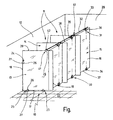
- the single FIGURE shows a schematic perspective representation of a series arrangement of a plurality of cabins which can be attached to a building wall or constructed in accordance with a preferred exemplary embodiment of the present invention
- a series arrangement 10 comprises, for example, three cabins 11, each of which can be mounted on or attached to an existing building wall 12. It is understood that instead of the existing building wall 12 and a specially provided for the series arrangement 10 of the cabins 11 rear wall can be arranged. It is further understood that the array 10 may have more or fewer cabins 11 than shown here; It is also possible to grow a single cabin 11 to a rear wall 12. Such a cabin 11 may be for a toilet, a shower, for a changing room or the like can be used.
- Each cabin 11 has two spaced side walls 13 and 14 and an access door 15. It is understood that in a row order 10 of cabins 11 each have a middle cabin one of the two side walls or both side walls 13, 14 with the adjacent cabin 11 in common.
- the side walls 13 and 14 and the access door 15, which consists essentially exclusively of a door leaf 16 which extends from one side wall 13 to the other side wall 14, are made of a laminated safety glass which is made opaque.
- the laminated safety glass is assembled in a manner not shown in detail from two single-pane safety glass, wherein the single-pane safety glass are glued together via a film.
- This adhesive film is responsible for the opacity.
- a colored adhesive film is used. It is also possible to use a cling film which has previously been made opaque by screen printing with a paint, a design, a photograph or the like. It is also possible to design or form the adhesive film so that the resulting laminated safety glass to one side and / or other side acts as a mirror.
- the end edge 19 is formed in a straight line and surmounted the door leaf 16 by about 50 to 100 mm.
- the door leaf 16 is dimensioned between the two side walls 13 and 14 so fitted that results in a gap of only about 3 to 5 mm on both sides.
- the door leaf 16 thus has substantially the width of the space of the cabin 11, which width is determined by the clearance of the two side walls 13 and 14 from each other. Due to the projecting front edge 19 and the narrow gap, a view from the outside into the cabin 11 is not possible.
- the front edge 19 may be configured differently, for example, from top to bottom sloping back and / or have a curved, wavy or other course.
- the side walls 13 and 14 are each held by means of two bottom bracket 23 and by means of a wall holder 24 on the building floor 22 and on the building wall 12.
- the two holders 23 and 24 are identical.
- the Holders 23 and 24 have an approximately U-shaped Klemmklebebauteil 26 for receiving the lower edge 17 and the rear edge 18 of the laminated safety glass of the side wall 13, 14 height or with a fixed to the building floor or on the building wall mounting rosette 27 or. is distance adjustable connected.
- the access door 15 is provided with a lower pivot fitting 30 and an upper pivot fitting 31 and connected via the relevant rotary fitting 30, 31 on the one hand to the building floor 22 and on the other hand with an upper connecting rail 32 rotatable or pivotally.
- Each rotary fitting 30 and 31 has an approximately U-shaped Klemmklebebauteil 36 for receiving the laminated safety glass of the door leaf 16.
- This Klemmklebebauteil 36 is connected to the lower pivot fitting with a fixed to the building floor 22 mounting rosette 34 and for the upper pivot fitting 31 with a boom 33, the longitudinally movably adjustable fastened to the connecting rail 32.
- the Klemmklebebauteil 36 of the rotary fitting 30, 31 is formed substantially corresponding to the Klemmklebebauteil 26 of the holders 23 and 24.
- the Klemmklebebauteil 36 may be connected to the mounting rosette 34 and the boom 33 via a sliding bearing or a roller bearing.
- this is a receiving pin on the mounting rosette 34 and am Boom 33 is provided, via which the clamping adhesive member 36 is pluggable.
- the rotary fittings 30 and 31 may be provided at any stop points of the longitudinal region of lower edge 37 and upper edge 38 of the door leaf 16. Preferably, this stop is located between one end and the center of the respective edge 37, 38 of the door leaf 16.
- the boom 33 in the longitudinal direction of the connecting rail 32 for aligning the access door 15 is displaceable.
- the connecting rail 32 is on one side (or in a manner not shown) also attached to both sides of a building side wall 29.
- holders 41 are provided with which the upper edge 20 of the side walls 13 and 14 are held on the connecting rail 32.
- These holders 41 are similar to the holders 23 and 24 are formed, ie they also have an approximately U-shaped Klemmklebebauteil 26 for receiving the glass wall, which is provided with a connecting rail 32 to the matching fastening part 42.
- This fastening part 42 is also adjustable along the connecting rail 32. This results in a stable construction for the side walls 13 and 14.
- the connecting rail 32 is reset according to the figure with respect to the plane of the access door 15 and, for example, formed as a tube. It is understood that in single cabins 11, the connecting rail 32 is stretched or secured only between two side walls 13 and 14.
- the holders 23 and 24 and the rotary fittings 30 are such that a desired spacing results between the respective edges 17, 18 of the side walls 13 and 14 or the access door 15 and the building floor or wall.
- a locking bolt is provided in a manner not shown.
- the side walls 13 and 14 and the access door 15 are provided at normal height, which is less than the ceiling height. It is understood that the side walls 13 and 14 and / or the access doors 15 can occupy room height. In this case, the respective upper fittings 31 and holder 41 are secured in the building ceiling. In addition, can be kept transparent in space-high configuration of the cabin components of the upper portion of the laminated safety glass.
Landscapes
- Engineering & Computer Science (AREA)
- Architecture (AREA)
- Civil Engineering (AREA)
- Structural Engineering (AREA)
- Securing Of Glass Panes Or The Like (AREA)
- Residential Or Office Buildings (AREA)
- Building Environments (AREA)
- Wing Frames And Configurations (AREA)
Abstract
Description
Die vorliegende Erfindung bezieht sich auf eine an eine Gebäudewand anbaubare Kabine für WC, Umkleide, Dusche oder dergleichen, nach dem Oberbegriff des Anspruchs 1 sowie auf eine Reihenanordnung solcher Kabinen nach dem Oberbegriff des Anspruchs 19 (siehe z.B.
Bei bekannten Kabinen dieser Art sind die Seitenwände und Türen aus Holz- oder Kunststoffpanelen, wobei zugangsseitig die Seitenwände mit rechtwinklig angesetzen vertikalen Rahmenteilen versehen sind, die das Scharnierband sowie das Schloss für die Zugangstür aufweisen. Zwischen der Zugangstür und den vertikalen Rahmenschenkeln sind entweder Abdichtungsprofile oder Überschläge vorgesehen, um einen Einblick von außen in die Kabine zu verhindern.In known cabins of this type, the side walls and doors are made of wood or plastic panels, the access side, the side walls are provided with rectangular vertical frame members, which have the hinge and the lock for the access door. Between the access door and the vertical frame legs are either Sealing profiles or flashovers provided to prevent a view from the outside into the cabin.
Vertikale Rahmenschenkel sind konstruktiv und montagetechnisch aufwendig und bedingen eine Verengung des Zugangs zur Kabine. Außerdem sind solche Kabine aufgrund ihres nicht unbedingt ansprechenden Designs für besondere Anwendungen nicht einbaubar, auch deshalb, weil sie den zur Verfügung stehenden Raum optisch zu sehr einengen.Vertical frame legs are structurally and assembly-technically complex and cause a narrowing of access to the cabin. In addition, such cabin are not installable due to their not necessarily appealing design for special applications, also because they visually restrict the available space too much.
Aufgabe der vorliegenden Erfindung ist es, eine Kabine der eingangs genannten Art zu schaffen, die montagetechnisch vereinfacht und in ihrem Design aufgewertet ist.Object of the present invention is to provide a cabin of the type mentioned, which is simplifies assembly technology and upgraded in its design.
Zur Lösung dieser Aufgabe sind bei einer Kabine der genannten Art die im Anspruch 1 angegebenen Merkmale und bei einer Reihenanordnung mehrerer solcher Kabine die im Anspruch 19 angegebenen Merkmale vorgesehen.To solve this problem, the features specified in claim 1 and in a series arrangement of several such cabin the features specified in
Durch die erfindungsgemäßen Maßnahmen ist eine vom Design her wesentlich günstigere Materialauswahl möglich und gegeben. Außerdem ist die Zugangstür ausschließlich als Türblatt ausgebildet, das somit über die gesamte Breite der Kabine verläuft und damit aus einer ununterbrochenen Fläche besteht. Diese verbreitert den Zugang zur Kabine zumindest optisch. Durch das Vorziehen der Stirnkante der Seitenwände gegenüber dem Türblatt der Zugangstür ist ein Einblick von außen in die Kabine nicht möglich. Dadurch ist die Konstruktion insoweit vereinfacht, als weder Abdichtungsprofile noch Türüberschläge notwendig sind.By the measures according to the invention a much cheaper material design is possible and given. In addition, the access door is designed exclusively as a door leaf, which thus extends over the entire width of the cabin and thus consists of an uninterrupted surface. This widened the access to the cabin, at least visually. By advancing the front edge of the side walls opposite the door leaf of the access door, a view from the outside into the cabin is not possible. As a result, the construction is simplified insofar as neither sealing profiles nor door rollovers are necessary.
Vorteilhafte Ausgestaltungen hinsichtlich der Verhinderung einer Einblickmöglichkeit von außen in die Kabine ergeben sich aus den Merkmalen des Anspruchs 2 und/oder 3. Dabei kann die Stirnkante jeder Seitenwand in vielfältiger Weise ausgebildet sein, also beispielsweise gebogen, wellenförmig oder auch entsprechend den Merkmalen des Anspruchs 4.Advantageous embodiments with respect to the prevention of an opportunity to look from the outside into the cabin arise from the features of claim 2 and / or 3. In this case, the front edge of each side wall may be formed in a variety of ways, that is, for example, bent, wavy or according to the features of claim 4 ,
Gemäß den Merkmalen des Anspruchs 5 oder 6 ist die Zugangstür bzw. das Türblatt sowohl mit einem unteren, als auch mit einem oberen Drehbeschlag versehen, so dass sich eine stabile drehbare Konstruktion ergibt. Bei raumhohen Zugangstüren ist es möglich, einen oberen Bereich der Zugangstür transparent zu belassen; entsprechendes kann dann gelten, wenn auch die Seitenwände raumhoch sind. Insbesondere bei sog. normalhohen Türen können die Merkmale gemäß Anspruch 7 vorgesehen sein.According to the features of claim 5 or 6, the access door or the door leaf is provided both with a lower, as well as with an upper rotary fitting, so that there is a stable rotatable construction. For floor-to-ceiling access doors, it is possible to leave an upper area of the access door transparent; The same can apply if the side walls are as high as room. In particular, in so-called. Normal height doors, the features may be provided according to claim 7.
Zur Verwirklichung einer optimalen Montage, sowie einer bauseitigen Option bei der Auswahl der Stelle, an der Drehbeschläge angeordnet werden sollen, ist es zweckmäßig, die Merkmale nach Anspruch 8 vorzusehen, was bedeutet, dass die Zugangstür bzw. dessen Türblatt insofern nicht durch Bohrungen oder dergleichen vorbereitet sein muss. Zweckmäßig ist es dabei, die Merkmale nach Anspruch 9 und/oder 10 vorzusehen.To achieve optimum installation, as well as an on-site option in the selection of the point at the rotary fittings are to be arranged, it is expedient to provide the features of claim 8, which means that the access door or its door leaf insofar does not have to be prepared by drilling or the like. It is expedient to provide the features of claim 9 and / or 10.
Entsprechendes gilt für die montagetechnische Seite der Seitenwände gemäß den Merkmalen des Anspruchs 11. Dabei ist es zweckmäßig, die Merkmale nach Anspruch 12 vorzusehen.The same applies to the technical assembly side of the side walls according to the features of
Um die Vielfalt der für die Seitenwände und Zugangstüren verwendete Beschläge einzugrenzen, sind die Merkmale nach Anspruch 13 vorgesehen.To limit the variety of fittings used for the side walls and access doors, the features of
Eine montagetechnische Vereinfachung ergibt sich dann, wenn die Merkmale nach Anspruch 14 vorgesehen sind, um auf diese Weise die Seitenwände und die Zugangstüren gegeneinander auszurichten.An assembly-technical simplification results when the features are provided according to
Vorteilhafte Ausgestaltungen hinsichtlich des Aufbaus des undurchsichtigen Glasmaterials für Seitenwände und Zugangstüren sind die Merkmale nach Anspruch 15 und ggf. den Merkmalen eines der Ansprüche 16, 17 und/oder 18 vorgesehen.Advantageous embodiments with regard to the structure of the opaque glass material for side walls and access doors, the features of claim 15 and optionally the features of any one of
Zur Ausgestaltung der Reihenanordnung von Kabinen nach Anspruch 19 ist es zur Stabilisierung der Seitenwände untereinander und der Zugangstüren sowie zur Ausrichtung der drehbeweglichen Zugangstüren zweckmäßig, die Merkmale eines oder mehrerer der Ansprüche 20 bis 22 vorzusehen.To design the series arrangement of cabins according to
Weitere Einzelheiten der Erfindung sind der folgenden Beschreibung zu entnehmen, in der die Erfindung anhand des in der Zeichnung dargestellten Ausführungsbeispieles näher beschrieben und erläutert ist.Further details of the invention can be found in the following description in which the invention with reference to the embodiment shown in the drawing is described and explained in more detail.
Die einzige Figur zeigt in schematischer perspektivischer Darstellung eine Reihenanordnung aus mehreren an eine Gebäudewand anbaubaren bzw. -angebauten Kabinen gemäß einem bevorzugten Ausführungsbeispiel vorliegender Erfindung,The single FIGURE shows a schematic perspective representation of a series arrangement of a plurality of cabins which can be attached to a building wall or constructed in accordance with a preferred exemplary embodiment of the present invention,
Bei dem in der Figur dargestellten Ausführungsbeispiel umfasst eine Reihenanordnung 10 beispielsweise drei Kabinen 11, die jeweils bzw. insgesamt an eine bestehende Gebäudewand 12 anbaubar bzw. angebaut sind. Es versteht sich, dass statt der bestehenden Gebäudewand 12 auch eine eigens für die Reihenanordnung 10 der Kabinen 11 vorgesehen Rückwand angeordnet sein kann. Es versteht sich ferner, dass die Reihenanordnung 10 mehr oder weniger Kabinen 11 als hier dargestellt, besitzen kann; es ist auch möglich, eine einzige Kabine 11 an eine Rückwand 12 anzubauen. Eine derartige Kabine 11 kann für ein WC, für eine Dusche, für eine Umkleide oder dergleichen verwendet werden.In the embodiment shown in the figure, a
Jede Kabine 11 besitzt zwei im Abstand angeordnete Seitenwände 13 und 14 sowie eine Zugangstür 15. Es versteht sich, dass bei einer Reihenordnung 10 von Kabinen 11 jeweils eine mittlere Kabine eine der beiden Seitenwände oder beide Seitenwände 13, 14 mit der Nachbarkabine 11 gemeinsam hat.Each
Die Seitenwände 13 und 14 sowie die Zugangstür 15, die im wesentlichen ausschließlich aus einem Türblatt 16 besteht, das sich von einer Seitenwand 13 zur anderen Seitenwand 14 erstreckt, sind aus einem Verbundsicherheitsglas hergestellt, das undurchsichtig gemacht ist. Hierzu ist das Verbundsicherheitsglas in nicht im einzelnen dargestellter Weise aus zwei Einscheibensicherheitsgläsern zusammengefügt, wobei die Einscheibensicherheitsgläser über eine Folie miteinander verklebt sind. Diese Klebefolie ist für die Undurchsichtigkeit verantwortlich. Hierzu wird beispielsweise eine farbige Klebefolie verwendet. Es ist auch möglich, eine Klarsichtfolie zu verwenden, die zuvor jedoch mittels Siebdruck mit einer Farbe, einem Design, einem Foto oder dergleichen undurchsichtig gemacht wird. Es ist auch möglich, die Klebefolie so zur gestalten, bzw. auszubilden, dass das daraus entstehende Verbundsicherheitsglas zu einen und/oder anderen Seite hin als Spiegel wirkt.The
Die beiden Seitenwände 13 und 14, die mittels ihrer vertikalen Rückkante 18 an der Gebäudewand 12 gehalten sind, überragen mit ihrer vertikalen vorderen Stirnkante 19 die Ebene der Zugangstür 15 bzw. von der Türblatt 16. Beim dargestellten Ausführungsbeispiel ist die Stirnkante 19 geradlinig ausgebildet und überragt das Türblatt 16 um etwa 50 bis 100 mm. Das Türblatt 16 ist dabei maßlich zwischen die beiden Seitenwände 13 und 14 derart eingepasst, dass sich zu beiden Seiten eine Fuge von lediglich etwa 3 bis 5 mm ergibt. Das Türblatt 16 hat somit im wesentlichen die Breite des Raumes der Kabine 11, welche Breite durch den lichten Abstand der beiden Seitenwände 13 und 14 voneinander bestimmt ist. Aufgrund der vorragenden Stirnkante 19 und der schmalen Fuge ist ein Einblick von Außen in die Kabine 11 nicht möglich. In nicht dargestellter Weise kann die Stirnkante 19 unterschiedlich ausgestaltet sein, beispielsweise von oben nach unten schräg zurückspringend verlaufen und/oder einen gebogenen, wellenförmigen oder sonstigen Verlauf aufweisen.The two
Die Seitenwände 13 und 14 sind jeweils mittels zweier Bodenhalter 23 sowie mittels eines Wandhalters 24 am Gebäudeboden 22 bzw. an der Gebäudewand 12 festgehalten. Die beiden Halter 23 und 24 sind identisch ausgebildet. Die Halter 23 und 24 besitzen ein etwa U-förmiges Klemmklebebauteil 26 zur Aufnahme der Unterkante 17 bzw. die Rückkante 18 des Verbundsicherheitsglases der Seitenwand 13, 14, das mit einer am Gebäudeboden bzw. an der Gebäudewand festgelegten Befestigungsrosette 27 höhen-bzw. abstandsverstellbar verbunden ist.The
Die Zugangstür 15 ist mit einem unteren Drehbeschlag 30 und einem oberen Drehbeschlag 31 versehen und über den betreffenden Drehbeschlag 30, 31 einerseits mit dem Gebäudeboden 22 und andererseits mit einer oberen Verbindungsschiene 32 dreh- bzw. schwenkbar verbunden. Jeder Drehbeschlag 30 und 31 besitzt ein etwa U-förmiges Klemmklebebauteil 36 zur Aufnahme des Verbundsicherheitsglases der Türblattes 16. Dieses Klemmklebebauteil 36 ist für den unteren Drehbeschlag mit einer am Gebäudeboden 22 festgelegten Befestigungsrosette 34 und für den oberen Drehbeschlag 31 mit einem Ausleger 33 verbunden, der an der Verbindungsschiene 32 längsbeweglich einstellbar befestigbar ist. Das Klemmklebebauteil 36 des Drehbeschlags 30, 31 ist im wesentlichen entsprechend dem Klemmklebebauteil 26 der Halter 23 und 24 ausgebildet. Das Klemmklebebauteil 36 kann mit der Befestigungsrosette 34 bzw. dem Ausleger 33 über ein Gleitlager oder ein Rollenlager verbunden sein. Vorzugsweise ist hierzu ein Aufnahmestift an der Befestigungsrosette 34 bzw. am Ausleger 33 vorgesehen, über das das Klemmklebebauteil 36 steckbar ist.The access door 15 is provided with a lower pivot fitting 30 and an upper pivot fitting 31 and connected via the relevant
Wie aus der Figur ersichtlich ist, können die Drehbeschläge 30 und 31 an beliebigen Anschlagstellen des Längsbereiches von Unterkante 37 und Oberkante 38 des Türblatts 16 vorgesehen sein. Vorzugsweise befindet sich diese Anschlagstelle zwischen einem Ende und der Mitte der betreffenden Kante 37, 38 des Türblatts 16. Wie erwähnt, ist der Ausleger 33 in Längsrichtung der Verbindungsschiene 32 zur Ausrichtung der Zugangstür 15 verschiebbar.As can be seen from the figure, the
Beim dargestellten Ausführungsbeispiel ist die Verbindungsschiene 32 einseitig (oder in nicht dargestellter Weise) auch beidseitig an einer Gebäudeseitenwand 29 befestigt. Darüber hinaus sind Halter 41 vorgesehen, mit denen die Oberkante 20 der Seitenwände 13 und 14 an der Verbindungsschiene 32 gehalten sind. Diese Halter 41 sind ähnlich den Haltern 23 und 24 ausgebildet, d.h. sie besitzen zur Aufnahme der Glaswand ebenfalls ein etwa U-förmiges Klemmklebebauteil 26, das mit einem zur Verbindungsschiene 32 passenden Befestigungsteil 42 versehen ist. Dieses Befestigungsteil 42 ist ebenfalls längs der Verbindungsschiene 32 verstellbar. Dadurch ergibt sich eine für die Seitenwände 13 und 14 stabile Einbaukonstruktion.In the illustrated embodiment, the connecting rail 32 is on one side (or in a manner not shown) also attached to both sides of a
Die Verbindungsschiene 32 ist gemäß der Figur gegenüber der Ebene der Zugangstür 15 zurückgesetzt und beispielsweise als Rohr ausgebildet. Es versteht sich, dass bei Einzelkabinen 11 die Verbindungsschiene 32 lediglich zwischen zwei Seitenwänden 13 und 14 gespannt bzw. befestigt ist.The connecting rail 32 is reset according to the figure with respect to the plane of the access door 15 and, for example, formed as a tube. It is understood that in
Die Halter 23 und 24 sowie die Drehbeschläge 30 sind derart, dass sich zwischen den jeweiligen Kanten 17, 18 der Seitenwände 13 und 14 bzw. der Zugangstür 15 und dem Gebäudeboden bzw. -wand ein gewünschter Abstand ergibt.The
An einer der Drehbeschlag-Anschlagstelle abgewandten vertikalen Seitenkante der Zugangstür 15 ist in nicht dargestellter Weise ein Verschlussriegel vorgesehen.At one of the rotary fitting stop point facing away from vertical side edge of the access door 15, a locking bolt is provided in a manner not shown.
Gemäß Figur 1 sind die Seitenwände 13 und 14 sowie die Zugangstür 15 in Normalhöhe vorgesehen, die geringer ist als die Raumhöhe. Es versteht sich, dass die Seitenwände 13 und 14 und/oder die Zugangstüren 15 Raumhöhe einnehmen können. In diesem Falle sind die betreffenden oberen Beschläge 31 bzw. Halter 41 in der Gebäudedecke befestigt. Außerdem kann bei raumhoher Ausgestaltung der Kabinenbauteile der obere Bereich des Verbundsicherheitsglases transparent gehalten werden.According to Figure 1, the
Claims (22)
- Cubicle (11), which can be built onto the wall of a building, for a WC, changing cubicle, shower or similar, comprising two side walls (13, 14) and an access door (15) rotatable about a vertical axis, characterized in that the side walls (13, 14) and the access door (15) are made of opaque glass, preferably safety glass, that the frameless access door (15) runs as a cubicle-wide door leaf (16) from one side wall (13, 14) to the other, that the front edges of the side walls (13, 14) project beyond the level of the closed access door (15) and that, on a longitudinal area of its lower edge, the access door (15) is mounted rotatably on the floor of the building.
- Cubicle according to claim 1, characterized in that the width of the joins between the side walls (13, 14) and the closed access door (15) lies within the range ≤ 5 mm.
- Cubicle according to claim 1 or 2, characterized in that the distance by which the side walls (13, 14) project beyond the closed access door (15) lies within the range ≤ 100 mm.
- Cubicle according to claim 3, characterized in that the distance by which the side walls (13, 14) project beyond the closed access door (15) decreases from top to bottom.
- Cubicle according to at least one of the claims 1 to 4, characterized in that the access door (15) is room-high and, in addition to a lower, floor-side swivel hinge (30), is provided with an upper, ceiling-side swivel hinge (31).
- Cubicle according to at least one of the claims 1 to 4, characterized in that the access door (15) is of normal height and, in addition to a lower, floor-side swivel hinge (30), is provided with an upper swivel hinge (31) which is mounted on a connecting rail (32) between the two side walls (13, 14).
- Cubicle according to claim 5 or 6, characterized in that the access door (15) and side walls (13, 14) are of equal height.
- Cubicle according to at least one of the claims 1 and 5 to 7, characterized in that the swivel hinges (30, 31) are designed such that the component on the access door side is a clamped/adhesive hinge component (36).
- Cubicle according to claim 8, characterized in that the clamped/adhesive hinge component (36) is pluggably connected with a fixed-position hinge component (34).
- Cubicle according to claims 8 and 9, characterized in that a roller bearing is provided between the clamped/adhesive hinge component (36) and the fixed-position hinge component (34).
- Cubicle according to at least one of the preceding claims, characterized in that the side walls (13, 14) are held to the floor and wall of the building by means of brackets (23, 24).
- Cubicle according to claim 11, characterized in that the brackets (23, 24) possesses a panel-side clamped/adhesive component (26) with integral fixed-position connection plate (27).
- Cubicle according to claims 8 and 12, characterized in that the clamped/adhesive component (36) of the swivel hinge (30, 31) is substantially identical to the clamped/adhesive component (26) of the brackets (23, 24).
- Cubicle according to at least one of the claims 8 to 13, characterized in that the swivel hinge (30, 31) and/or the brackets (23, 24) is/are adjustable in height.
- Cubicle according to at least one of the preceding claims, characterized in that the side walls (13, 14) and the access door (15) are made of laminated safety glass composed of two single panes of safety glass bonded together through interlayering of an adhesive film.
- Cubicle according to claim 15, characterized in that the adhesive film is an opaque coloured film.
- Cubicle according to claim 15, characterized in that the adhesive film is transparent and printed.
- Cubicle according to claim 15, characterized in that the adhesive film is in the form of a mirror film.
- Row arrangement (10) of cubicles (11) according to claim 1 and where applicable at least one of the subsequent claims, characterized in that a connecting rail (32) is provided which is connected with all side walls (13, 14) at a point on the upper edge of the side walls opposite the building wall and which carries a rotary bearing (31) for each access door (15).
- Row arrangement according to claim 19, characterized in that a clamped/adhesive rail bracket (35) corresponding to the clamped/adhesive brackets (23, 24) is provided between the connecting rail (32) and the side walls (13, 14).
- Row arrangement according to claim 19 or 20, characterized in that the upper rotary bearing (31) for the access door (15) is connected with the connecting rail (32) in a longitudinally adjustable way via an extension (33).
- Row arrangement according to at least one of the claims 19 to 21, characterized in that the connecting rail (32) is formed by a bracing tube.
Applications Claiming Priority (2)
| Application Number | Priority Date | Filing Date | Title |
|---|---|---|---|
| DE102004020992A DE102004020992A1 (en) | 2004-04-23 | 2004-04-23 | Cabin attachable to a building wall |
| DE102004020992 | 2004-04-23 |
Publications (3)
| Publication Number | Publication Date |
|---|---|
| EP1589164A2 EP1589164A2 (en) | 2005-10-26 |
| EP1589164A3 EP1589164A3 (en) | 2006-08-09 |
| EP1589164B1 true EP1589164B1 (en) | 2008-09-24 |
Family
ID=34935293
Family Applications (1)
| Application Number | Title | Priority Date | Filing Date |
|---|---|---|---|
| EP05008391A Active EP1589164B1 (en) | 2004-04-23 | 2005-04-18 | Cabins mountable against a building wall |
Country Status (3)
| Country | Link |
|---|---|
| EP (1) | EP1589164B1 (en) |
| AT (1) | ATE409261T1 (en) |
| DE (2) | DE102004020992A1 (en) |
Families Citing this family (2)
| Publication number | Priority date | Publication date | Assignee | Title |
|---|---|---|---|---|
| DE202011103996U1 (en) | 2011-07-29 | 2011-10-19 | Astec Gmbh Design Beschlaege | Locking device for a frameless door, in particular for a cabin |
| FR3064016B1 (en) * | 2017-03-17 | 2019-03-29 | Olivier Moinon | RETRACTABLE CLOTHES |
Family Cites Families (10)
| Publication number | Priority date | Publication date | Assignee | Title |
|---|---|---|---|---|
| DE7428733U (en) * | 1975-03-20 | Munch P | Kit for creating a shower cubicle | |
| FR1603207A (en) * | 1968-10-03 | 1971-03-22 | ||
| DE7404938U (en) * | 1973-02-19 | 1974-07-18 | Dite Protectal Sa | Kit for the production of toilet cubicles, shower cubicles, changing cubicles and the like |
| FR2283285A1 (en) * | 1974-08-30 | 1976-03-26 | Schaefer Werke Kg | Construction element for toilet cubicle - has outer panel skins joined at double folded edges |
| DE2501759A1 (en) * | 1975-01-17 | 1976-07-22 | Inver Gmbh Fuer Ind Flachglasv | Metal-framed prestressed-glass panels changing cubicle - with horizontal edge metal profiles running through to vertical edges |
| DE3326790A1 (en) * | 1982-08-07 | 1984-02-09 | Henry 2944 Wittmund Schwitters | Shower partition |
| DE8517676U1 (en) * | 1985-06-18 | 1985-09-19 | Knierim GmbH + Co KG Metall- und Kunststoffverarbeitung, 3500 Kassel | Changing cubicle block, consisting of several changing cubicles |
| US4881353A (en) * | 1987-04-21 | 1989-11-21 | Braendel & Associates, Inc. | Cubicle |
| DE10001449A1 (en) * | 2000-01-15 | 2001-07-26 | Arcon Dur Arnold & Conzelmann | Functional wall systems for sanitary rooms |
| AU2002355429A1 (en) * | 2001-08-08 | 2003-02-24 | Spectrum Products, Inc. | Apparatus for automatic application of sunless tanning composition having an attached dressing room |
-
2004
- 2004-04-23 DE DE102004020992A patent/DE102004020992A1/en not_active Withdrawn
-
2005
- 2005-04-18 EP EP05008391A patent/EP1589164B1/en active Active
- 2005-04-18 AT AT05008391T patent/ATE409261T1/en active
- 2005-04-18 DE DE502005005447T patent/DE502005005447D1/en active Active
Also Published As
| Publication number | Publication date |
|---|---|
| DE102004020992A1 (en) | 2005-11-24 |
| DE502005005447D1 (en) | 2008-11-06 |
| ATE409261T1 (en) | 2008-10-15 |
| EP1589164A2 (en) | 2005-10-26 |
| EP1589164A3 (en) | 2006-08-09 |
Similar Documents
| Publication | Publication Date | Title |
|---|---|---|
| DE10021330A1 (en) | Adjustable hinge for hanging door or window has grip flanges with screw adjusters to set spacing and alignment | |
| EP0658662B1 (en) | Glass-façade with window | |
| EP0784956A1 (en) | Shower partition | |
| EP1589164B1 (en) | Cabins mountable against a building wall | |
| EP0174583A2 (en) | Shower screen | |
| DE4236376A1 (en) | Shower partition | |
| DE4318209C2 (en) | Door stop profile for swing doors | |
| DE202019102112U1 (en) | Profile unit for roller shutter guide and attachment of at least one fall arrest element on a window frame or pillar of a window | |
| DE29602765U1 (en) | Shower partition that can be adjusted to different widths | |
| DE3639990A1 (en) | PARTITION FOR SHOWER | |
| DE19719113C2 (en) | Door system | |
| DE69527282T2 (en) | BUILT-IN BALCONY | |
| DE202008009183U1 (en) | facade element | |
| CH692474A5 (en) | Shower enclosure. | |
| CH672000A5 (en) | ||
| AT502153A1 (en) | INSULATING ELEMENT | |
| EP1038486B1 (en) | Kit for shower partitions | |
| DE4241321A1 (en) | ||
| EP3461982B1 (en) | Door assembly | |
| DE3618482A1 (en) | Corner element for wall or door elements which are intended, in particular, for producing sanitary unitised units | |
| EP3832065B1 (en) | Guide profile for a window or a door with a roller shutter box | |
| EP1038490A2 (en) | Shower system | |
| DD289702A5 (en) | SHOWER SCREEN | |
| DE2501759A1 (en) | Metal-framed prestressed-glass panels changing cubicle - with horizontal edge metal profiles running through to vertical edges | |
| EP0582873A1 (en) | Shower enclosure |
Legal Events
| Date | Code | Title | Description |
|---|---|---|---|
| PUAI | Public reference made under article 153(3) epc to a published international application that has entered the european phase |
Free format text: ORIGINAL CODE: 0009012 |
|
| AK | Designated contracting states |
Kind code of ref document: A2 Designated state(s): AT BE BG CH CY CZ DE DK EE ES FI FR GB GR HU IE IS IT LI LT LU MC NL PL PT RO SE SI SK TR |
|
| AX | Request for extension of the european patent |
Extension state: AL BA HR LV MK YU |
|
| PUAL | Search report despatched |
Free format text: ORIGINAL CODE: 0009013 |
|
| AK | Designated contracting states |
Kind code of ref document: A3 Designated state(s): AT BE BG CH CY CZ DE DK EE ES FI FR GB GR HU IE IS IT LI LT LU MC NL PL PT RO SE SI SK TR |
|
| AX | Request for extension of the european patent |
Extension state: AL BA HR LV MK YU |
|
| 17P | Request for examination filed |
Effective date: 20060927 |
|
| AKX | Designation fees paid |
Designated state(s): AT CH DE FR GB IT LI |
|
| GRAP | Despatch of communication of intention to grant a patent |
Free format text: ORIGINAL CODE: EPIDOSNIGR1 |
|
| GRAS | Grant fee paid |
Free format text: ORIGINAL CODE: EPIDOSNIGR3 |
|
| GRAA | (expected) grant |
Free format text: ORIGINAL CODE: 0009210 |
|
| AK | Designated contracting states |
Kind code of ref document: B1 Designated state(s): AT CH DE FR GB IT LI |
|
| REG | Reference to a national code |
Ref country code: GB Ref legal event code: FG4D Free format text: NOT ENGLISH |
|
| REG | Reference to a national code |
Ref country code: CH Ref legal event code: EP Ref country code: CH Ref legal event code: NV Representative=s name: MICHELI & CIE SA |
|
| REF | Corresponds to: |
Ref document number: 502005005447 Country of ref document: DE Date of ref document: 20081106 Kind code of ref document: P |
|
| PLBE | No opposition filed within time limit |
Free format text: ORIGINAL CODE: 0009261 |
|
| STAA | Information on the status of an ep patent application or granted ep patent |
Free format text: STATUS: NO OPPOSITION FILED WITHIN TIME LIMIT |
|
| PG25 | Lapsed in a contracting state [announced via postgrant information from national office to epo] |
Ref country code: IT Free format text: LAPSE BECAUSE OF FAILURE TO SUBMIT A TRANSLATION OF THE DESCRIPTION OR TO PAY THE FEE WITHIN THE PRESCRIBED TIME-LIMIT Effective date: 20080924 |
|
| 26N | No opposition filed |
Effective date: 20090625 |
|
| REG | Reference to a national code |
Ref country code: FR Ref legal event code: ST Effective date: 20091231 |
|
| PG25 | Lapsed in a contracting state [announced via postgrant information from national office to epo] |
Ref country code: FR Free format text: LAPSE BECAUSE OF NON-PAYMENT OF DUE FEES Effective date: 20091222 |
|
| REG | Reference to a national code |
Ref country code: DE Ref legal event code: R082 Ref document number: 502005005447 Country of ref document: DE Representative=s name: PATENTANWAELTE MAGENBAUER & KOLLEGEN PARTNERSC, DE |
|
| REG | Reference to a national code |
Ref country code: DE Ref legal event code: R082 Ref document number: 502005005447 Country of ref document: DE Representative=s name: PATENTANWAELTE MAGENBAUER & KOLLEGEN PARTNERSC, DE Ref country code: DE Ref legal event code: R081 Ref document number: 502005005447 Country of ref document: DE Owner name: ASTEC GMBH DESIGN BESCHLAEGE, DE Free format text: FORMER OWNER: ASTEC GMBH DESIGN BESCHLAEGE, 72458 ALBSTADT, DE |
|
| PGFP | Annual fee paid to national office [announced via postgrant information from national office to epo] |
Ref country code: CH Payment date: 20190424 Year of fee payment: 15 |
|
| PGFP | Annual fee paid to national office [announced via postgrant information from national office to epo] |
Ref country code: GB Payment date: 20190424 Year of fee payment: 15 Ref country code: AT Payment date: 20190416 Year of fee payment: 15 |
|
| REG | Reference to a national code |
Ref country code: CH Ref legal event code: PL |
|
| REG | Reference to a national code |
Ref country code: AT Ref legal event code: MM01 Ref document number: 409261 Country of ref document: AT Kind code of ref document: T Effective date: 20200418 |
|
| PG25 | Lapsed in a contracting state [announced via postgrant information from national office to epo] |
Ref country code: LI Free format text: LAPSE BECAUSE OF NON-PAYMENT OF DUE FEES Effective date: 20200430 Ref country code: AT Free format text: LAPSE BECAUSE OF NON-PAYMENT OF DUE FEES Effective date: 20200418 Ref country code: CH Free format text: LAPSE BECAUSE OF NON-PAYMENT OF DUE FEES Effective date: 20200430 |
|
| GBPC | Gb: european patent ceased through non-payment of renewal fee |
Effective date: 20200418 |
|
| PG25 | Lapsed in a contracting state [announced via postgrant information from national office to epo] |
Ref country code: GB Free format text: LAPSE BECAUSE OF NON-PAYMENT OF DUE FEES Effective date: 20200418 |
|
| PGFP | Annual fee paid to national office [announced via postgrant information from national office to epo] |
Ref country code: DE Payment date: 20240328 Year of fee payment: 20 |