EP1589059B1 - Leitfähiges polymer enthaltende verbundstruktur - Google Patents
Leitfähiges polymer enthaltende verbundstruktur Download PDFInfo
- Publication number
- EP1589059B1 EP1589059B1 EP20030810597 EP03810597A EP1589059B1 EP 1589059 B1 EP1589059 B1 EP 1589059B1 EP 20030810597 EP20030810597 EP 20030810597 EP 03810597 A EP03810597 A EP 03810597A EP 1589059 B1 EP1589059 B1 EP 1589059B1
- Authority
- EP
- European Patent Office
- Prior art keywords
- devices
- conductive
- conductive polymer
- polymer composite
- composite structures
- Prior art date
- Legal status (The legal status is an assumption and is not a legal conclusion. Google has not performed a legal analysis and makes no representation as to the accuracy of the status listed.)
- Expired - Lifetime
Links
- 229920001940 conductive polymer Polymers 0.000 title claims abstract description 357
- 239000002131 composite material Substances 0.000 title claims abstract description 192
- 238000005452 bending Methods 0.000 claims abstract description 23
- 239000000758 substrate Substances 0.000 claims description 145
- 238000000034 method Methods 0.000 claims description 96
- 238000003825 pressing Methods 0.000 claims description 62
- 230000008569 process Effects 0.000 claims description 59
- 238000006116 polymerization reaction Methods 0.000 claims description 44
- 230000008602 contraction Effects 0.000 claims description 16
- 239000000835 fiber Substances 0.000 claims description 13
- 239000007784 solid electrolyte Substances 0.000 claims description 13
- 230000003028 elevating effect Effects 0.000 claims description 8
- 238000004804 winding Methods 0.000 claims description 6
- 230000001105 regulatory effect Effects 0.000 claims description 5
- 238000006073 displacement reaction Methods 0.000 abstract description 20
- 229910052751 metal Inorganic materials 0.000 description 93
- 239000002184 metal Substances 0.000 description 93
- 239000008151 electrolyte solution Substances 0.000 description 36
- 239000010410 layer Substances 0.000 description 34
- 230000007246 mechanism Effects 0.000 description 23
- 230000000052 comparative effect Effects 0.000 description 22
- 150000002739 metals Chemical class 0.000 description 22
- 230000033001 locomotion Effects 0.000 description 18
- 230000003287 optical effect Effects 0.000 description 18
- 239000003792 electrolyte Substances 0.000 description 17
- 239000000463 material Substances 0.000 description 16
- -1 polyphenylene Polymers 0.000 description 15
- KAESVJOAVNADME-UHFFFAOYSA-N Pyrrole Chemical compound C=1C=CNC=1 KAESVJOAVNADME-UHFFFAOYSA-N 0.000 description 14
- 239000002019 doping agent Substances 0.000 description 10
- 239000000178 monomer Substances 0.000 description 9
- 239000000126 substance Substances 0.000 description 9
- 238000004519 manufacturing process Methods 0.000 description 8
- 230000036961 partial effect Effects 0.000 description 8
- OKTJSMMVPCPJKN-UHFFFAOYSA-N Carbon Chemical compound [C] OKTJSMMVPCPJKN-UHFFFAOYSA-N 0.000 description 7
- 150000001450 anions Chemical class 0.000 description 7
- 125000004429 atom Chemical group 0.000 description 7
- 229910052799 carbon Inorganic materials 0.000 description 7
- 238000012545 processing Methods 0.000 description 7
- 239000004065 semiconductor Substances 0.000 description 7
- 238000012360 testing method Methods 0.000 description 7
- 230000005540 biological transmission Effects 0.000 description 6
- 239000004020 conductor Substances 0.000 description 6
- 230000001276 controlling effect Effects 0.000 description 6
- 230000000474 nursing effect Effects 0.000 description 6
- 239000000523 sample Substances 0.000 description 6
- 239000000853 adhesive Substances 0.000 description 5
- 230000001070 adhesive effect Effects 0.000 description 5
- 238000004140 cleaning Methods 0.000 description 5
- 150000001875 compounds Chemical class 0.000 description 5
- 210000004247 hand Anatomy 0.000 description 5
- 239000000203 mixture Substances 0.000 description 5
- 238000005498 polishing Methods 0.000 description 5
- 239000011347 resin Substances 0.000 description 5
- 229920005989 resin Polymers 0.000 description 5
- 239000002904 solvent Substances 0.000 description 5
- 239000003115 supporting electrolyte Substances 0.000 description 5
- FAPWRFPIFSIZLT-UHFFFAOYSA-M Sodium chloride Chemical compound [Na+].[Cl-] FAPWRFPIFSIZLT-UHFFFAOYSA-M 0.000 description 4
- YTPLMLYBLZKORZ-UHFFFAOYSA-N Thiophene Chemical compound C=1C=CSC=1 YTPLMLYBLZKORZ-UHFFFAOYSA-N 0.000 description 4
- 238000006243 chemical reaction Methods 0.000 description 4
- 239000011248 coating agent Substances 0.000 description 4
- 238000000576 coating method Methods 0.000 description 4
- 125000001153 fluoro group Chemical group F* 0.000 description 4
- 239000011521 glass Substances 0.000 description 4
- 239000004973 liquid crystal related substance Substances 0.000 description 4
- 238000000465 moulding Methods 0.000 description 4
- 210000003205 muscle Anatomy 0.000 description 4
- 229910052759 nickel Inorganic materials 0.000 description 4
- 229910052697 platinum Inorganic materials 0.000 description 4
- 238000003466 welding Methods 0.000 description 4
- XTHFKEDIFFGKHM-UHFFFAOYSA-N Dimethoxyethane Chemical compound COCCOC XTHFKEDIFFGKHM-UHFFFAOYSA-N 0.000 description 3
- 229910045601 alloy Inorganic materials 0.000 description 3
- 239000000956 alloy Substances 0.000 description 3
- 210000000078 claw Anatomy 0.000 description 3
- 238000009826 distribution Methods 0.000 description 3
- 230000005611 electricity Effects 0.000 description 3
- 238000011156 evaluation Methods 0.000 description 3
- 238000011049 filling Methods 0.000 description 3
- 235000013305 food Nutrition 0.000 description 3
- 229910052737 gold Inorganic materials 0.000 description 3
- 238000001746 injection moulding Methods 0.000 description 3
- 150000002500 ions Chemical class 0.000 description 3
- 239000007788 liquid Substances 0.000 description 3
- 238000003754 machining Methods 0.000 description 3
- 238000007747 plating Methods 0.000 description 3
- 230000002787 reinforcement Effects 0.000 description 3
- 150000003839 salts Chemical class 0.000 description 3
- BDHFUVZGWQCTTF-UHFFFAOYSA-M sulfonate Chemical compound [O-]S(=O)=O BDHFUVZGWQCTTF-UHFFFAOYSA-M 0.000 description 3
- 238000012546 transfer Methods 0.000 description 3
- 229910052721 tungsten Inorganic materials 0.000 description 3
- 235000012431 wafers Nutrition 0.000 description 3
- 101100165186 Caenorhabditis elegans bath-34 gene Proteins 0.000 description 2
- 229910000990 Ni alloy Inorganic materials 0.000 description 2
- 229910001080 W alloy Inorganic materials 0.000 description 2
- 230000015572 biosynthetic process Effects 0.000 description 2
- 239000000969 carrier Substances 0.000 description 2
- 239000011162 core material Substances 0.000 description 2
- 230000000694 effects Effects 0.000 description 2
- 239000000945 filler Substances 0.000 description 2
- 239000012530 fluid Substances 0.000 description 2
- 239000000446 fuel Substances 0.000 description 2
- 125000000524 functional group Chemical group 0.000 description 2
- 239000007789 gas Substances 0.000 description 2
- 238000003384 imaging method Methods 0.000 description 2
- 230000006872 improvement Effects 0.000 description 2
- 238000001459 lithography Methods 0.000 description 2
- 238000011068 loading method Methods 0.000 description 2
- 150000002894 organic compounds Chemical class 0.000 description 2
- 230000010355 oscillation Effects 0.000 description 2
- 229920000128 polypyrrole Polymers 0.000 description 2
- 238000007639 printing Methods 0.000 description 2
- 150000003233 pyrroles Chemical class 0.000 description 2
- 230000009467 reduction Effects 0.000 description 2
- 229910052709 silver Inorganic materials 0.000 description 2
- 238000004088 simulation Methods 0.000 description 2
- 239000002356 single layer Substances 0.000 description 2
- 239000011780 sodium chloride Substances 0.000 description 2
- 238000005476 soldering Methods 0.000 description 2
- 238000003756 stirring Methods 0.000 description 2
- 238000003860 storage Methods 0.000 description 2
- 229910052715 tantalum Inorganic materials 0.000 description 2
- 229930192474 thiophene Natural products 0.000 description 2
- 229910052719 titanium Inorganic materials 0.000 description 2
- XLYOFNOQVPJJNP-UHFFFAOYSA-N water Substances O XLYOFNOQVPJJNP-UHFFFAOYSA-N 0.000 description 2
- LYTMVABTDYMBQK-UHFFFAOYSA-N 2-benzothiophene Chemical compound C1=CC=CC2=CSC=C21 LYTMVABTDYMBQK-UHFFFAOYSA-N 0.000 description 1
- 241000251468 Actinopterygii Species 0.000 description 1
- LSNNMFCWUKXFEE-UHFFFAOYSA-M Bisulfite Chemical class OS([O-])=O LSNNMFCWUKXFEE-UHFFFAOYSA-M 0.000 description 1
- ZOXJGFHDIHLPTG-UHFFFAOYSA-N Boron Chemical compound [B] ZOXJGFHDIHLPTG-UHFFFAOYSA-N 0.000 description 1
- 208000002177 Cataract Diseases 0.000 description 1
- 235000015842 Hesperis Nutrition 0.000 description 1
- 235000012633 Iberis amara Nutrition 0.000 description 1
- AFCARXCZXQIEQB-UHFFFAOYSA-N N-[3-oxo-3-(2,4,6,7-tetrahydrotriazolo[4,5-c]pyridin-5-yl)propyl]-2-[[3-(trifluoromethoxy)phenyl]methylamino]pyrimidine-5-carboxamide Chemical compound O=C(CCNC(=O)C=1C=NC(=NC=1)NCC1=CC(=CC=C1)OC(F)(F)F)N1CC2=C(CC1)NN=N2 AFCARXCZXQIEQB-UHFFFAOYSA-N 0.000 description 1
- 240000007594 Oryza sativa Species 0.000 description 1
- 235000007164 Oryza sativa Nutrition 0.000 description 1
- OAICVXFJPJFONN-UHFFFAOYSA-N Phosphorus Chemical compound [P] OAICVXFJPJFONN-UHFFFAOYSA-N 0.000 description 1
- 239000004698 Polyethylene Substances 0.000 description 1
- 229920000265 Polyparaphenylene Polymers 0.000 description 1
- 239000004743 Polypropylene Substances 0.000 description 1
- 125000000217 alkyl group Chemical group 0.000 description 1
- 229910052787 antimony Inorganic materials 0.000 description 1
- WATWJIUSRGPENY-UHFFFAOYSA-N antimony atom Chemical compound [Sb] WATWJIUSRGPENY-UHFFFAOYSA-N 0.000 description 1
- 239000007864 aqueous solution Substances 0.000 description 1
- 229910052785 arsenic Inorganic materials 0.000 description 1
- RQNWIZPPADIBDY-UHFFFAOYSA-N arsenic atom Chemical compound [As] RQNWIZPPADIBDY-UHFFFAOYSA-N 0.000 description 1
- 239000008280 blood Substances 0.000 description 1
- 210000004369 blood Anatomy 0.000 description 1
- 230000036772 blood pressure Effects 0.000 description 1
- 210000001124 body fluid Anatomy 0.000 description 1
- 239000010839 body fluid Substances 0.000 description 1
- 229910052796 boron Inorganic materials 0.000 description 1
- 235000008429 bread Nutrition 0.000 description 1
- 239000003575 carbonaceous material Substances 0.000 description 1
- 239000000919 ceramic Substances 0.000 description 1
- 230000008859 change Effects 0.000 description 1
- 238000002485 combustion reaction Methods 0.000 description 1
- 238000004891 communication Methods 0.000 description 1
- 230000000536 complexating effect Effects 0.000 description 1
- 238000013329 compounding Methods 0.000 description 1
- 238000000748 compression moulding Methods 0.000 description 1
- 238000010276 construction Methods 0.000 description 1
- 238000005520 cutting process Methods 0.000 description 1
- 230000003247 decreasing effect Effects 0.000 description 1
- 238000001514 detection method Methods 0.000 description 1
- 238000007599 discharging Methods 0.000 description 1
- RTZKZFJDLAIYFH-UHFFFAOYSA-N ether Substances CCOCC RTZKZFJDLAIYFH-UHFFFAOYSA-N 0.000 description 1
- 210000003414 extremity Anatomy 0.000 description 1
- 238000001125 extrusion Methods 0.000 description 1
- 239000004744 fabric Substances 0.000 description 1
- 229910052736 halogen Inorganic materials 0.000 description 1
- 238000010438 heat treatment Methods 0.000 description 1
- 229910052734 helium Inorganic materials 0.000 description 1
- 239000001307 helium Substances 0.000 description 1
- SWQJXJOGLNCZEY-UHFFFAOYSA-N helium atom Chemical compound [He] SWQJXJOGLNCZEY-UHFFFAOYSA-N 0.000 description 1
- 125000005842 heteroatom Chemical group 0.000 description 1
- 150000002391 heterocyclic compounds Chemical class 0.000 description 1
- 125000002887 hydroxy group Chemical group [H]O* 0.000 description 1
- 229910001090 inconels X-750 Inorganic materials 0.000 description 1
- 230000010365 information processing Effects 0.000 description 1
- 238000007689 inspection Methods 0.000 description 1
- 239000011810 insulating material Substances 0.000 description 1
- 238000010884 ion-beam technique Methods 0.000 description 1
- 239000004922 lacquer Substances 0.000 description 1
- 238000010030 laminating Methods 0.000 description 1
- 230000014759 maintenance of location Effects 0.000 description 1
- 230000000873 masking effect Effects 0.000 description 1
- 238000005259 measurement Methods 0.000 description 1
- 238000002844 melting Methods 0.000 description 1
- 230000008018 melting Effects 0.000 description 1
- 229910001092 metal group alloy Inorganic materials 0.000 description 1
- 125000000449 nitro group Chemical group [O-][N+](*)=O 0.000 description 1
- 125000005245 nitryl group Chemical group [N+](=O)([O-])* 0.000 description 1
- 229910052755 nonmetal Inorganic materials 0.000 description 1
- 150000002843 nonmetals Chemical class 0.000 description 1
- 239000013307 optical fiber Substances 0.000 description 1
- 230000003647 oxidation Effects 0.000 description 1
- 238000007254 oxidation reaction Methods 0.000 description 1
- 125000005429 oxyalkyl group Chemical group 0.000 description 1
- 238000004806 packaging method and process Methods 0.000 description 1
- 238000010422 painting Methods 0.000 description 1
- 239000002245 particle Substances 0.000 description 1
- 238000005192 partition Methods 0.000 description 1
- 229910052698 phosphorus Inorganic materials 0.000 description 1
- 239000011574 phosphorus Substances 0.000 description 1
- 238000000206 photolithography Methods 0.000 description 1
- 239000004033 plastic Substances 0.000 description 1
- 229920003023 plastic Polymers 0.000 description 1
- 229920000767 polyaniline Polymers 0.000 description 1
- 229920000573 polyethylene Polymers 0.000 description 1
- 229920000642 polymer Polymers 0.000 description 1
- 229920005594 polymer fiber Polymers 0.000 description 1
- 230000000379 polymerizing effect Effects 0.000 description 1
- 229920001155 polypropylene Polymers 0.000 description 1
- 239000004810 polytetrafluoroethylene Substances 0.000 description 1
- 229920001343 polytetrafluoroethylene Polymers 0.000 description 1
- 229920000123 polythiophene Polymers 0.000 description 1
- 239000011148 porous material Substances 0.000 description 1
- 239000000843 powder Substances 0.000 description 1
- 230000001141 propulsive effect Effects 0.000 description 1
- 238000006479 redox reaction Methods 0.000 description 1
- 230000002829 reductive effect Effects 0.000 description 1
- 238000011069 regeneration method Methods 0.000 description 1
- 239000012779 reinforcing material Substances 0.000 description 1
- 230000004044 response Effects 0.000 description 1
- 230000000284 resting effect Effects 0.000 description 1
- 235000009566 rice Nutrition 0.000 description 1
- KQFAFFYKLIBKDE-UHFFFAOYSA-M sodium;ethanesulfonate Chemical compound [Na+].CCS([O-])(=O)=O KQFAFFYKLIBKDE-UHFFFAOYSA-M 0.000 description 1
- KKVTYAVXTDIPAP-UHFFFAOYSA-M sodium;methanesulfonate Chemical compound [Na+].CS([O-])(=O)=O KKVTYAVXTDIPAP-UHFFFAOYSA-M 0.000 description 1
- 238000009987 spinning Methods 0.000 description 1
- 238000005507 spraying Methods 0.000 description 1
- 125000001174 sulfone group Chemical group 0.000 description 1
- 239000000725 suspension Substances 0.000 description 1
- 239000004753 textile Substances 0.000 description 1
- 238000009732 tufting Methods 0.000 description 1
- 230000005641 tunneling Effects 0.000 description 1
- 210000000707 wrist Anatomy 0.000 description 1
Images

Classifications
-
- F—MECHANICAL ENGINEERING; LIGHTING; HEATING; WEAPONS; BLASTING
- F16—ENGINEERING ELEMENTS AND UNITS; GENERAL MEASURES FOR PRODUCING AND MAINTAINING EFFECTIVE FUNCTIONING OF MACHINES OR INSTALLATIONS; THERMAL INSULATION IN GENERAL
- F16F—SPRINGS; SHOCK-ABSORBERS; MEANS FOR DAMPING VIBRATION
- F16F15/00—Suppression of vibrations in systems; Means or arrangements for avoiding or reducing out-of-balance forces, e.g. due to motion
- F16F15/005—Suppression of vibrations in systems; Means or arrangements for avoiding or reducing out-of-balance forces, e.g. due to motion using electro- or magnetostrictive actuation means
-
- Y—GENERAL TAGGING OF NEW TECHNOLOGICAL DEVELOPMENTS; GENERAL TAGGING OF CROSS-SECTIONAL TECHNOLOGIES SPANNING OVER SEVERAL SECTIONS OF THE IPC; TECHNICAL SUBJECTS COVERED BY FORMER USPC CROSS-REFERENCE ART COLLECTIONS [XRACs] AND DIGESTS
- Y10—TECHNICAL SUBJECTS COVERED BY FORMER USPC
- Y10T—TECHNICAL SUBJECTS COVERED BY FORMER US CLASSIFICATION
- Y10T428/00—Stock material or miscellaneous articles
- Y10T428/31504—Composite [nonstructural laminate]
- Y10T428/31551—Of polyamidoester [polyurethane, polyisocyanate, polycarbamate, etc.]
-
- Y—GENERAL TAGGING OF NEW TECHNOLOGICAL DEVELOPMENTS; GENERAL TAGGING OF CROSS-SECTIONAL TECHNOLOGIES SPANNING OVER SEVERAL SECTIONS OF THE IPC; TECHNICAL SUBJECTS COVERED BY FORMER USPC CROSS-REFERENCE ART COLLECTIONS [XRACs] AND DIGESTS
- Y10—TECHNICAL SUBJECTS COVERED BY FORMER USPC
- Y10T—TECHNICAL SUBJECTS COVERED BY FORMER US CLASSIFICATION
- Y10T428/00—Stock material or miscellaneous articles
- Y10T428/32—Composite [nonstructural laminate] of inorganic material having metal-compound-containing layer and having defined magnetic layer
- Y10T428/325—Magnetic layer next to second metal compound-containing layer
Definitions
- the present invention relates to conductive polymer composite structures in which conductive polymers and conductive substrate are composite, process for producing the same, process for producing conductive polymers, bundles and stacked layers of conductive polymer composite structures.
- Conductive polymers such as polypyrrole are known to have electrochemomechanical deformation, phenomena of expansion and contraction by electrochemical redox reaction. Recently, this electrochemomechanical deformation of conductive polymers has been attracting public attention, because this is expected to be applied for the use of artificial muscles, robot arms, artificial arms, actuators and applications not only for smaller equipments such as for micro machines but also for larger machines have been attracting public attention as well.
- a process by electrochemical polymerization method includes by adding monomer components such as pyrrole in electrolytic solution, providing a working electrode and a counter electrode in this electrolyte, and applying voltage between the electrodes, thereby forming conductive polymers as films on the working electrode (e.g. see pages 70 to 73, "Conductive polymers” 8th edition by Naoya Ogata, published by Scientific K.K, February 10, 1990 ").
- Conductive polymers obtained by electrochemical polymerization can be subject to displacement such as expansion-contraction or bending by applying voltage to conductive polymers formed like films.
- conductive polymer elements When elements which include conductive polymers manufactured by electrochemical polymerization (hereinafter called conductive polymer elements) are used as actuators in a driving part for uses of large sized equipments such as robot arms of industrial robots, and artificial muscles such as artificial hands, compared with elements for the uses of small sized actuators such as for micro machines, it is necessary to make sizes of elements large enough to obtain larger amount of expansion-contraction or larger electrochemical stress. Therefore, in order to enlarge sizes of conductive polymer elements, it is necessary that conductive polymer films obtained by electrochemical polymerization are processed to be longer or thicker by piling up plural of films.
- Desirable electrochemical strain can be obtained by selecting the kinds of conductive polymers and dopants depending on the uses and by controlling the length of conductive polymer elements since deformation ratio of conductive polymer elements is determined by the kinds of conductive polymers and dopants which are included in conductive polymer elements.
- conductive polymers are liable to be cut during the operation process because mechanical strength of conductive polymers themselves is not high, it is difficult to form desirable conductive polymer electrodes, that is, with an external diameter or width of less than 1 mm by processing such as cutting conductive polymer films obtained by electrochemical polymerization in order to obtain small-sized conductive polymer elements represented by micro machines such as nano machines and catheters.
- processing such as cutting conductive polymer films obtained by electrochemical polymerization in order to obtain small-sized conductive polymer elements represented by micro machines such as nano machines and catheters.
- conductive polymer elements are hard to be melted, production methods such as extrusion moldings and injection moldings cannot be employed, the methods usually employed in producing thin lines such as wires or cylindrical resin mold products.
- actuator elements which are driven to make expanding and contracting motion or to make bending motion by electrochemomechanical deformation of conductive polymers are not put into practical uses as small sized driving parts which include nano machines and micro machines. Therefore, in order to use for small sized elements represented by nano machines and micro machines, it is also desirable to obtain actuator elements which are driven to make expanding and contracting motion or to make bending motion by electrochemomechanical deformation of conductive polymers as small sized elements with external diameter or width of less than 1 mm.
- the present invention relates to conductive polymer composite structures comprising conductive substrates and conductive polymers, wherein said conductive substrates are filled by said conductive polymers and have deformation property, said conductive substrates are in the form of springs, meshes, or fiber structure sheets, and conductivity of said conductive substrates is not less than 1.0 ⁇ 10 3 S/cm.
- said conductive polymer composite structures deformation property is good even when the conductive polymer composite structures are used as larger sized actuator elements. Since said conductive polymer composite structures are provided with structures capable of applying potential to whole elements even when they are used as conductive polymer elements elongated in size in the length direction and in height direction, satisfactory voltage can be applied for driving end portions when used as actuators.
- the present invention relates to a process for producing conductive polymer composite structures in which electrode holders which can be immersed in an electrolytic bath are immersed in electrolytic solution and then conductive polymers and conductive substrates are combined by electrochemical polymerization interposing electrolyte between a counter electrode and a working electrode and since the present invention relates to a process for producing conductive polymer composite structures in which said working electrode holders are provided with working electrodes, working electrode terminal portions, and electrode holder portions and in which said working electrodes are attached to said working electrode terminal portions, and said working electrodes include at least coiled conductive substrates.
- electrochemical polymerization is conducted in a state where counter electrodes are put in the vicinity of working electrodes, a large number of conductive polymer composite structures can easily be obtained for short times at the same time.
- the present invention also relates to a process for producing conductive polymer composite structures in which bundles in which coiled conductive substrates are bundled are used as said working electrodes.
- Conductive polymer composite structures of the present invention are conductive polymer composite structures comprising conductive substrates and conductive polymers, wherein said conductive substrates have deformation property, and conductivity of said conductive substrates is not less than 1.0 ⁇ 10 3 S/c m.
- shapes of conductive polymer composite structures of the present invention and forms in which conductive substrates are included in the conductive polymer composite structures of the present invention are explained by using drawings, however, shapes of conductive polymer composite structures and forms in which conductive substrates are included in the conductive polymer composite structures of the present invention are not limited to what are illustrated in these drawings as long as conductive polymer composite structures can obtain satisfactory displacement such as expansion and contraction or bending as practical performances.
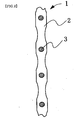
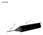
- Fig.1 is a typical perspective view of conductive polymer composite structures of the present invention when coiled metal spring-type members are used as conductive substrates.
- Fig.2 is a partial enlarged view of a longitudinal section of conductive polymer composite structures in Fig.1 .
- conductive polymer composite structure 1 in Fig.1 coiled metal spring-type member 3 is used as a conductive substrate.
- conductive polymer composite structure 1 in Fig.1 In cylindrical conductive polymer composite structure 1 in Fig.1 , spaces between wires which compose coiled metal spring-type members are filled by conductive polymer 2, and conductive polymer 2 and conductive substrate 3 are complexed.
- conductive polymer composite structures in Fig.1 include coiled metal spring-type members, wires of metal spring-type members can function as reinforcement materials when external force is applied from the direction vertical to an outer surface, improvement in mechanical strength can also be attained.
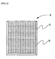
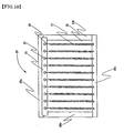
- Fig.3 is a typical perspective view of conductive polymer composite structures of the present invention when metal meshes which are network members are used as conductive substrates.
- cylindrical conductive polymer composite structure 4 in Fig.3 spaces between wires which compose metal mesh are filled and conductive polymer 5 and conductive substrate 6 are complexed.
- conductive polymer composite structures can produce satisfactory displacement such as expansion and contraction or bending as practical performances.
- wires of metal spring-type members can function as reinforcement materials when external force such as tension is applied, improvement in mechanical strength can also be attained.
- said conductive polymer substrates have space portions as shown in Figs. 1 and 3 between conductive wires which compose coiled metal spring-type members and metal mesh, said space portions are not specifically limited.
- conductive polymer composite structures in which space portions are filled by conductive polymers can be obtained.
- conductive substrates are metal meshes with large openings
- metal plates are used as auxiliary electrode substrates, and by applying electrochemical polymerization using said metal meshes laminated on said metal plates as working electrodes, followed by removing said metal plates, conductive polymer composite structures in which metal mesh space portions are filled by conductive polymers can be obtained.
- said conductive polymer substrates may be provided with space portions which are other than wires , such as leaf springs.
- Said conductive substrates may be included in such a way that satisfactory potential is applied over said whole conductive polymer composite structures, and as shown in Figs. 1 and 3 , said conductive substrates may be arranged in the vicinity of a center of conductive polymer composite structures in the thickness direction or said conductive substrates may be arranged in the vicinity of surfaces of conductive polymer composite structures, however, it is preferable that said conductive substrates may be arranged in the vicinity of a center of conductive polymer composite structures in the thickness direction since satisfactory potential can be easily applied to the whole elements.
- said conductive substrates are included in substantially whole said conductive polymer composite structures since satisfactory potential can be easily applied to the whole elements, and it is preferable that said conductive substrates have the same shapes as those of said conductive polymer composite structures since satisfactory potential can be easily applied to the whole elements.
- Shapes of said conductive polymer composite structures are not specifically limited and as desired, they may be prepared in columnar shapes, prismatic shapes, plate shapes, sheet shapes, tubular shapes, and cylindrical shapes.
- said conductive polymer composite structures may be cylindrical shapes as shown in Fig.1 or said conductive polymer composite structures may be film-like shapes as shown in Fig.3 .
- said conductive polymer composite structures may be processed to make them desired shapes as required when the size of elements is large and when the process can easily be made.
- columnar conductive polymer composite structures may be obtained by winding film-like conductive polymer composite structures shown in Fig.3 and by filling conductive polymers in communicating space portions in cylindrical shaped conductive polymer composite structures of Fig. 1 .
- coiled metal spring-type members may be prepared in the form of an expander, thereby compounding aligned conductive substrates fixed in parallel in a stretchable way with conductive polymers, or conductive polymer composite structures with metal meshes may be laminated.
- desired process may be applied.
- groups of conductive polymer composite structures can be formed by forming bundles of a plural of conductive polymer composite structures which use coiled metal spring-type members as conductive substrates, further followed by bundling the conductive polymer composite structures.
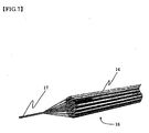
- Fig.5 is a drawing of cylindrical conductive polymer composite structures using coiled metal spring-type members as conductive substrates.
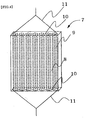
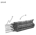
- Fig.6 is a partial enlarged perspective view of one end regarding bundles (the first bundles of conductive polymer composite structures) of columnar conductive polymer composite structures obtained by bundling cylindrical conductive polymer composite structures shown in Fig.5 .
- Fig.7 is a partial enlarged perspective view of one end regarding groups of bundles (the second bundles of conductive polymer composite structures) of columnar conductive polymer composite structures obtained by bundling the first bundles of conductive polymer composite structures shown in Fig.6 .
- Fig.8 is a partial enlarged perspective view of one end regarding bundles of groups (the third bundles of conductive polymer composite structures) of conductive polymer composite structures obtained by bundling the groups of cylindrical conductive polymer composite structures shown in Fig.7 .
- conductive polymer composite structures 12 are tubular conductive polymer composite structures obtained by jointing metal wires 13 or 13' at both ends of coiled metal spring-type members in the length direction as a conductive substrate, connecting said metal wires 13 and 13' to a power supply and generating conductive polymers on a conductive substrate by a publicly known electrochemical polymerization method.
- conductive polymer composite structures 12 are provided with metal wires on both ends, the metal wire may be provided on either end thereof.
- bundles 14 of conductive polymer composite structures are the first bundles of conductive polymer composite structures obtained by bundling conductive polymer composite structures 12. By making bundles of conductive polymer composite structures, when they are driven as actuators, larger electrochemical stress can be obtained compared with conductive polymer composite structures. Methods of bundling conductive polymer composite structures to obtain bundles of conductive polymer composite structures are not specifically limited as long as they are the methods of bundling publicly known linear object. In the embodiment in Fig.6 , metal wires 13 provided at the end of conductive polymer composite structures 12 are bundled to form a bundle of metal wires 15.
- Methods of fixing a bundle of metal wires in a state where the metals are bundled are not specifically limited and such methods may include forming coated films with adhesives around the outer periphery of a bundle of metal wires or fixing a state where the metals are bundled by wrenching metal wires.
- bundles of conductive polymer composite structures are provided with a bundle of metal wires in which conductive polymer composite structures are fixed with metal wires on both ends of conductive polymer composite structures bundled on both ends.
- potential may be applied either to metal wires of both ends of conductive polymer composite structures or to one end thereof.
- groups of conductive polymer composite structures 16 are the second bundles of conductive polymer composite structures obtained by bundling bundles 14 of conductive polymer composite structures.
- groups of bundles of conductive polymer composite structures when driven as actuators, the groups of bundles of conductive polymer composite structures can obtain larger electrochemical stress compared with bundles of conductive polymer composite structures.
- Methods of bundling bundles of conductive polymer composite structures to produce groups of bundles of conductive polymer composite structures are not specifically limited as long as they are the methods of bundling publicly known linear objects.
- metal wire bundle groups 17 are formed.
- Methods of fixing groups of metal wire bundles in a state where metal wire bundles are bundled are not specifically limited and such methods may include forming coated films with adhesives around the outer periphery of a group of metal wire bundles or fixing a state where the metal wire bundles are bundled by wrenching metal wire bundles to form a group.
- groups of bundles 16 of seven conductive polymer composite structures are further bundled, thereby forming bundles 18 of groups of conductive polymer composite structures.
- groups of conductive polymer composite structures when driven as actuators, by combining groups of bundles of conductive polymer composite structures depending on required electrochemical stress, desired electrochemical stress can be obtained.
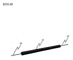
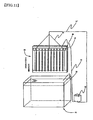
- Fig. 9 shows one embodiment of driving members 23 of actuators using said bundles of conductive polymer composite structures.
- Bundles 19 of four conductive polymer composite structures are fitted in pores provided with fixing members 20 and 20' and are fixed by adhesives.
- Metal wires provided in bundles of four conductive polymer composite structures form metal wire groups 21 in a bundle, and are connected to a power source interposing a lead.
- catching portion 22 provided in fixing member 20' wires positioned in operating objects are connected.
- Actuators can be formed by impregnating driving members 23 in electrolytic solution, and by coating solid electrolytes and driving members with resins by placing solid electrolytes in a way to make them contact with bundles of conductive polymer composite structures.
- conductive polymer composite structures By applying voltage to conductive polymer composite structures, conductive polymer composite structures deform and wires connected to catching portions 22 are pulled, thereby making objects move.
- bundles used as driving members of actuators are not specifically limited in numbers used and depending on required electrochemical stress, not less than 100-unit bundle such as about 1000-unit bundle can be used.
- tubular, cylindrical and prismatic shapes may be formed, and for example, tubular can be formed by arranging about 600-unit conductive polymer-metal wire composites.
- said fixing members can show effect of bundling composites by fixing a position of conductive polymer-metal wire composites and by fixing conductive polymer composite structures to said fixing members.
- Conductive substrates included in conductive polymer composite structures of the present invention have deformation property and conductive ratio of said conductive substrates is not less than 1.0 ⁇ 10 3 S/cm. Since said conductive substrates have its conductivity of not less than 1.0 ⁇ 10 3 S/cm, even when the size of conductive polymer composite structures which include said conductive substrates are made to be large, displacement for practical use such as expansion and contract as actuators becomes available.
- Materials of said conductive substrates are not specifically limited as long as they show deformation property and have its conductivity of not less than 1.0 ⁇ 10 3 S/cm. It is preferable that said materials are metals, metal plated polymer fibers, and carbon materials from the view point of conductivity and mechanical strength. It is preferable that structures of said conductive substrates are structures capable of extending and contracting when conductive substrates have conductive property with conductivity of not less than 1.0 ⁇ 10 3 S/cm by including non-deformation property materials such as metals. Conductive substrates in which conductive substrates and conductive polymers are complexed, by having stretchable conductive substrates, displacement for practical use such as expansion and contract as actuators becomes available. In addition, said conductive polymer composite structures can have improved mechanical strength since conductive substrates can function as core materials in said conductive polymer composite structures.
- Said stretchable structures are not specifically limited as long as they are stretchable. Unlike plate structures or line segment structures, it is preferable that said stretchable structures have structures provided with structures having space between members which compose conductive substrates such as coiled springs, plate springs, and meshes on longitudinal section.
- conductive substrates such as coiled springs, plate springs, and meshes on longitudinal section.
- stretchable structures spring-shaped members, meshed members, fiber structure sheets are exemplified as exemplars.
- stretchable structures are spring-shaped members, they are not specifically limited as long as they are stretchable and for example, rolled springs, plate springs, coiled springs can be used as conductive substrates.
- said stretchable structures are meshed members, they are not specifically limited as long as they are stretchable and for example, meshed members in which meshed space portions are polygons such as quadrangles, hexagons, and octagons can be used.
- meshed members in which meshed space portions are polygons such as quadrangles, hexagons, and octagons can be used.
- spaced portions are not specifically limited, when expansion and contraction is liable to occur in only one direction due to the shapes, such conductive polymer composite structures can be obtained that can control expansion and contraction in specific directions and when expansion and contraction is liable to occur in several directions such as hexagons due to the shapes, it is preferable to obtain such conductive polymer composite structures that can expand and contract in other directions such as right to left or up and down.
- Said meshed members may be the meshed members with a single layer provided with meshed spaced portions represented by metal meshes or they may be the meshed members in which plural of layers provided with meshed spaced portions are stacked .
- said meshed members may be honeycomb structures in which spaces are formed in honeycomb.
- stretchable structures they may be stretchable fiber structure sheets.
- fiber structure sheets they may be any one of knitted works, textiles, and non woven cloths and deformation property can be shown depending on sheet structures, yarn characteristics, and yarn structures, however, plain stitches, circular rib stitches, and purl stitches with good deformation property or fiber structure sheets of knitted fabrics by weft knit composed of combinations thereof are preferable since deformation property can easily be obtained.
- conductive substrates may be formed by conductive metals or core materials may be coated with conductive metals by plating.
- said conductive substrates are fiber structure sheets, it is preferable that the fibers which make up fiber structure sheets are coated with conductive metals by plating.
- Conductive property of conductive substrates included in conductive polymers of the present invention may show conductivity of not less than 1.0 ⁇ 10 3 S/cm as conductive substrates and the substrates may be composed of conductive materials such as conductive metals and carbons, or surfaces of the substrates may be coated with conductive materials such as conductive metals and carbons. With the conductivity of not less than 1.0 ⁇ 10 3 S/cm as said conductive substrates, even when conductive polymer composite structures with enlarged size in the length direction or height direction are used, sufficient potential for displacement such as expansion and contraction can be applied to the whole element.
- conductive substrates including conductive metal metal alloys such as those of Ag, Ni, Ti, Au, Pt, W or other alloys such as SUS can be used.
- said conductive substrates include a single substance of metals regarding the element of Pt, W, Ni, Ta in order to obtain conductive polymers with a large expansion and contraction performance, and among them, W alloys and Ni alloys are particularly preferable.
- conductive polymers included in conductive polymer composite structures of the present invention publicly known conductive polymers can be used, which include polypyrrole, polythiophene, polyaniline, polyphenylene.
- said conductive polymers are conductive polymers which include pyrrole and/or pyrrole derivatives in molecular chains not only for stability as conductive polymers but also for excellent electrochemomechanical deformation.
- said conductive polymers show excellent deformation ratio per redox cycle in electrochemomechanical deformation and displacement ratio per specific time, it is preferable that said conductive polymers include anions which include trifluoromethanesulfonate ion and /or plural of fluorine atoms which bond to central atom as dopants.
- the present invention relates to layered structures which include conductive polymer-containing layers and solid electrolyte layers, in which said conductive polymer-containing layers are provided with conductive polymer composite structures which include conductive substrates and conductive polymers, in which said conductive substrates have deformation property and in which conductivity of said conductive substrates is not less than 1.0 ⁇ 10 3 S/cm. Since said stacked layers include said conductive polymer-containing layers and said solid electrolyte layers, electrolytes in said solid electrolytes are provided in said conductive polymer-containing layers and even when not in liquid electrolytic solution, displacement such as expansion and contract or bending as actuators can be made.
- said conductive polymer-containing layers in said electrolytes and said solid electrolyte layers directly contact with each other, other layers can be interposed therebetween as long as electrolytes in said solid electrolytes can be made to move to said conductive polymers.
- said cylindrical stacked layers may be formed by filling solid electrolytes in a communicated space portions.
- cylindrical stacked layers may be formed by winding the conductive polymer composite structures in Fig.3 around the outer surfaces of cylindrical solid electrolytes.
- the present invention relates to a process for producing conductive polymers by electrochemical polymerization using conductive substrates as working electrodes in which said conductive substrates have deformation property and the conductivity of said conductive substrates is not less than 1.0 ⁇ 10 3 S/cm.
- conductive substrates having similar rough contour shapes are used as working electrodes.
- cylindrical conductive polymer composite structures can easily be obtained by electrochemical polymerization and without conducting any process by using coiled metal spring-shaped members whose rough contour is cylindrical as conductive substrates.
- cylindrical conductive polymer composite structures can be obtained as shown in Fig.1 .
- electrochemical polymerization by applying voltage to coiled spring-shaped members made of metals which are working electrodes, conductive polymers are polymerized on a wire surface and conductive polymers grow from surfaces of working electrodes. By this growth, as shown in Fig.2 , spaces between wire materials which make up coiled spring members made of metals are filled in and cylindrical conductive polymer composite structures shown in Fig. 1 can be obtained.
- Fig.3 shows conductive polymer composite structures in which metal meshes are used as working electrodes at the time of electrochemical polymerization in the process for producing conductive polymers of the present invention.
- electrochemical polymerization by applying potential to metal meshes which are working electrodes, conductive polymers are obtained on a wire material surface of metal meshes and conductive polymers grow. By this growth, like when coiled springs are used as working electrodes, spaces between wire materials which make up metal meshes are filled in and plate like conductive polymer composite structures shown in Fig.3 can be obtained.
- sizes of conductive substrates used as working electrodes are not specifically limited and large sized conductive substrates may be used such as metal meshes with not less than 50mm ⁇ 50mm and coiled spring-shaped members made of metals whose outer diameters are not less than 3 mm, or small sized conductive substrates may also be used such as coiled spring-shaped members made of metals whose diameter is several dozen ⁇ m.
- a process for producing conductive polymers of the present invention is a process for producing conductive polymer composite structures which can preferably be used particularly as easily obtaining conductive polymer composite structures available as large sized actuator elements or small-sized actuator elements.
- actuator elements can be obtained which are driven to expand and contract or bend by electrochemomechanical deformation of conductive polymers with outer diameters or width of less than 1 mm without any process in order to obtain desired sizes and shapes of actuator elements in the obtained conductive polymer composite structures.
- conductive polymers are electrochemically polymerized using large-sized conductive substrates for working electrodes in the process for producing conductive polymers of the present invention, conductive polymer composite structures which can be used as large-sized actuator elements can easily be obtained.
- electrochemical polymerization As methods of electrochemical polymerization used in the process of producing conductive polymers, it is possible to use publicly known methods of electrochemical polymerization as electrochemical polymerization of monomers of conductive polymers. Therefore, publicly known electrolytic solution and monomers of conductive polymers can be used and any one of constant potential methods, constant current methods, and potential sweep methods can be used for example, said electrochemical polymerization is preferably conducted under the condition where the current density is 0.01 to 20 mA/cm 2 and reaction temperature is -70 to 80°C, preferably current density of 0.1 to 2 mA/cm 2 and reaction temperature of -40 to 40°C, and more preferably, reaction temperature of -20 to 30°C.
- electrolytic solution which includes organic compounds as solvents can be used. It is preferable that said organic compounds include (1) chemical bonding selected at least one from the groups of chemical bond made up of ether bond, ester bond, carbon-halogen and carbonate bond and/or (2) functional groups selected at least one from the groups of functional groups made up of hydroxyl groups, nitro groups, sulfone groups, and nitryl groups in molecules.
- publicly known dopant may be included in said electrolytic solution and in order to obtain larger deformation ratio per redox cycle, it is preferable to include trifluoromethanesulfonate ion and/or anions including plural of fluorine atoms bonding to a central atom.
- trifluoromethanesulfonate ion and/or anions including plural of fluorine atoms bonding to a central atom.
- perfluoroalkylsulfonylimide ion represented by chemical formula (1) instead of using trifluoromethanesulfonate ion and/or anions including plural of fluorine atoms bonding to a central atom.
- monomers of conductive polymers included in electrolytic solution for electrochemical polymerization are not specifically limited as long as they are compounds which become polymers by oxidation by electrochemical polymerization and show conductivity, and examples include five-membered heterocyclic compounds such as pyrrole, thiophene and isothianaphthene and derivatives of alkyl groups and oxyalkyl groups thereof.
- hetero five-membered ring compounds such as pyrrole, and thiophene or derivatives thereof are preferable and particularly, conductive polymers including pyrrole and/or pyrrole derivatives are preferable for easy production process and stability as conductive polymers.
- the above monomers can be used together in combinations of two or more of them.
- the present invention also relates to a process for producing conductive polymer composite structures comprising the steps of impregnating electrode holders in an electrolytic bath in electrolytic solution, followed by turning on electricity interposing electrolytic solution between a counter electrode and a working electrode and electrochemically polymerizing, thereby obtaining structures in which conductive polymers and conductive substrates are complexed, wherein said holders of working electrodes are provided with working electrodes, a terminal portion of working electrodes and electrode holder portions, and said working electrodes are attached to said terminal portion of working electrodes and said working electrodes include at least coiled conductive substrates.
- Electrode holders 24 are provided with a terminal portion of working electrodes 25 and working electrodes 27 are connected to a terminal portion of working electrodes 25 interposing connection lines 28 in connecting portion 26 of working electrodes.
- Ni plates with longer sideways are used as a terminal portion of working electrodes 25.
- shapes of a terminal portion of working electrodes are not specifically limited and they may be cylindrical and meshed.
- materials of said terminal portion of working electrodes are not specifically limited as long as they show conductivity and as long as said working electrodes can be set and conductive materials such as metals and non-metals can be used.
- ten working electrodes are attached to a terminal portion of working electrodes and a working electrode 4 is bundled to form one by twisting four coiled conductive substrates, and plural of working electrodes 27 are positioned in a terminal portion of working electrodes 25, thereby forming a group of working electrodes.
- electrochemical polymerization may be conducted with one working electrode and compared with when each of many conductive substrates are subject to electrochemical polymerization separately followed by bundling with one electrochemical polymerization process, time can greatly be reduced.
- said conductive substrates show conductivity of not less than 1.0 ⁇ 10 3 S/cm and they may be formed by conductive materials such as conductive metals and carbon and the surface of them may be coated with conductive materials such as conductive metals, and carbon by plating. With the conductivity of not less than 1.0 ⁇ 10 3 S/cm as said conductive substrates, even when conductive polymer composite structures with enlarged size in the length direction or height direction are used, sufficient potential for displacement such as expansion and contract can be applied to the whole element.
- conductive substrates which include conductive metals, metal such as Ag, Ni, Ti, Au, Pt, Ta, W, or alloys thereof, and other alloys such as SUS can be used. In particular, it is preferable that said conductive substrates are W alloys and Ni alloys in order to obtain conductive polymers which operate stably in operational electrolytic solution.
- said working electrodes may be one coiled conductive substrate with each working electrode or may be bundles in which coiled conductive substrates are bundled.
- coiled conductive substrates used as said working electrodes are long, resistance becomes large since metal wires are narrow and long due to coiled conductive substrates which are working electrodes, and as the conductive substrates get longer, transmission of potential gets worse and formation of conductive polymers on conductive substrates becomes difficult.
- by making said working electrodes bundles in which coiled conductive substrates are bundled at the time of electrochemical polymerization, stable potential can be provided to the whole conductive substrates and the efficiency of electrochemical polymerization improves and time for producing process can be shortened.
- conductive polymer composite structures obtained by electrochemical polymerization using said bundles are in the state where plural of conductive substrates are complexed with conductive polymers in which plural of conductive substrates are bundled together, compared with the process for obtaining conductive polymer composite structures by complexing each of coiled conductive substrates separately, the space of an electrolyte bath can be saved and the same effect can be obtained when many conductive substrates are complexed at once.
- forms of said bundles used as working electrodes are not limited as long as the forms have structures in which motion at the time of expansion and contraction is not inhibited with upward and downward of plural coils of conductive substrates connected to so that plural of coiled conductive substrates contact with each other to make potential substantially constant.
- forms of said bundles can be selected from bundling coiled conductive substrates like an expander, tubular structures in which coiled conductive substrates are arranged like cylinders, bundling coiled conductive substrates by twisting, depending on how conductive polymer composite structures are used.
- said bundles are not specifically limited, it is preferable that said bundles are bundles composed of four to one hundred coiled conductive substrates for good workability and efficiency of electrochemical polymerization and such bundles do not inhibit deformation property of conductive polymer composite structures.
- connection wire 28 is connected to working electrode terminal portion 25 at working electrode connection portion 26 by soldering in which connection wire 28 is connected to the upper part of working electrode 27 when the lengthwise direction for said electrode 27 is arranged in the vertical direction.
- methods of fixing said connection portion of a working electrode are not specifically limited as long as electric conductivity is available by said methods and such methods may be selected from soldering, conductive adhesion, spot welding, clip-on, or screw fastening in which connection wires are fixed by screw heads.
- connection wires need not be requisite ones and said working electrodes may be directly connected to a terminal portion of working electrodes and it is preferable that the electrode holders of the present invention are provided with conductive connection wires made of metals in order to facilitate the operation of attaching working electrodes to a terminal portion of working electrodes.
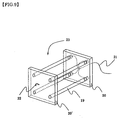
- electrode holders 24 are provided with plate-like electrode fixing portions 29a, 29b, 29c, and 29d whose thickness is substantially the same and said electrode fixing portions form frame-like shapes.
- counter electrodes 30 are fixed on back surfaces of electrode fixing portions 29a, 29b, 29c, and 29d combined in frame-like shapes. Since working electrode terminal portions 25 are provided on a face of electrode fixing portion 29a and counter electrodes are fixed on back surfaces of electrode fixing portions, the spaces between counter electrodes in each working electrode become substantially the same and the amount of conductive polymer included in each of obtained conductive polymer composite structures can easily be made substantially constant.
- the spaces between counter electrodes in each working electrode are not specifically limited as long as conductive polymer can be formed on working electrodes by electrochemical polymerization, the spaces are preferably 1 to 50 mm.
- the space between a working electrode and a counter electrode is less than 1 mm, short circuit is liable to occur by the contact of working electrodes and electrodes, and on the other hand, when the space between a working electrode and a counter electrode is larger than 50 mm, voltage becomes too much with constant current methods causing electrolytes to deteriorate, causing performance of generated conductive polymers to lower, and with constant potential methods, electrolytic current becomes extremely small and it takes time to form desired amount of conductive polymers in on working electrodes.
- counter electrodes need not always be fixed to holders of working electrodes.
- Holders of working electrodes may be fixed in the specified position of an electrolytic bath so that the spaces between counter electrodes in each working electrode with said counter electrodes fixed to an electrolytic bath.
- electrode holders are provided with four electrode fixing portions, however, they are not always plural and any shapes such as all-in one frame shapes may be used so long as they do not block off between counter electrodes and working electrodes.
- electrode fixing portions having small areas can be obtained and therefore, resource saving is available by providing working electrode terminal portions on plate-shaped electrode fixing portions with long side ways and by fixing them on a specific position of the upper part of an electrolyte bath so that the working electrodes connected to working electrode terminal portions hang vertically downward when counter electrodes are fixed to an electrolytic bath.
- said electrode fixing portions are formed by insulating materials in order to avoid direct conductivity of counter electrodes and working electrodes and although they may be plastics, ceramics, glasses, and insulating coating metals, polypropylene, PTFE, polyethylene, and glass are more preferably used as easy formation and for good resistance to solvents.
- said electrode fixing portions do not have insulating property, by sandwiching an insulating sheet between working electrode terminal portions and electrode fixing portions or between electrode fixing portions and counter electrodes, direct conductivity of counter electrodes and working electrodes can be avoided.
- the shapes of counter electrodes are not specifically limited as long as conductivity is available between counter electrodes and working electrodes and shapes may be plate-shaped, meshed, coiled, bar-shaped and cylindrical.
- said counter electrodes are not specifically limited as long as they have conductive property and metals such as Ni, Au, Pt or carbon may be included.
- Fig.11 shows the state in which a lead for turning on electricity on electrode holders between counter electrodes and working electrodes in the process for producing conductive polymer composite structures of the present invention.
- Three leads 31 are connected to working electrode terminal portion 25 provided in electrode holders 24 and interposing lead 31', they are connected to power supply 32.
- leads 10 are also connected to counter electrode 7 and they are also connected to power supply 9.
- electrode holders 24 are impregnated in an electrolytic bath 34 provided with electrolytic solution 35 and electrochemical polymerization is conducted with potential applied by power supply 32.
- methods for retaining the state of impregnating electrode holders 24 in an electrolytic bath 34 are not specifically limited, and other than methods of suspending electrode holders, methods include inserting electrode holders in an electrolyte bath providing slots, leaving electrode holders in a form of self-standing state such as containing them in a box in an electrolyte bath and various methods can be used which will fit the shapes and sizes of an electrolyte bath. Further, when electrode holders are immersed in an electrolyte bath, it is preferable that whole electrode holders are immersed in an electrolytic solution except working electrode terminal portions so that conductive polymers are not generated on working electrode terminal portions.
- leads 31 are connected to working electrode terminal portions 25 in which the space between connecting portions of three leads 31 and working electrode terminal portions 25 are equal so that constant potential can be applied to each portion of the whole working electrode terminal portions 25 which are Ni metal plates, the number of leads which are connected to working electrode terminal portions are not specifically limited in the process for producing conductive polymer composite structures of the present invention.
- leads which are connected to said working electrode terminal portions are connected to working electrode terminal portions in required numbers so that stable potential could be provided to the whole working electrode terminal portions depending on materials of working electrode terminal portions.
- conductive polymers are generated on plural of working electrodes provided in electrode holders by conducting electrochemical polymerization comprising the steps of impregnating electrode holders in an electrolytic solution, followed by turning on electricity interposing electrolyte between counter electrodes and working electrodes.
- supporting electrolytes for electrochemomechanical deformation are not specifically limited, it is preferable that said electrolytic solution includes compounds selected at least one from the group of trifluoromethanesulfonate ion, anions including plural of fluorine atoms which bond to central atom and sulfonate with a carbon number of not greater than 3 as supporting electrolytes.
- the reason is that by making compounds selected at least one from the group of trifluoromethanesulfonate ion, anions including plural of fluorine atoms which bond to central atom, and sulfonate with a carbon number of not greater than 3 as supporting electrolytes, further large electrochemomechanical deformation per redox can be obtained.
- Trifluoromethanesulfonate ion included in electrolytic solution for expanding and contracting said conductive polymer composite structures as operational electrolytic solution is a compound represented by the chemical formula of CF 3 SO 3 - .
- anions which include plural of fluorine atoms which bond to central atom is the ion having structures in which plural of fluorine atoms bond to central atom such as boron, phosphorus, antimony and arsenic.
- sulfonate with a carbon number of not greater than 3 are not specifically limited as long as they are salts of sulfonic acid with a carbon number of not greater than 3 and for example, sodium methanesulfonate and sodium ethanesulfonate can be used.
- Said electrolytic solution may be aqueous solution which includes sodium chloride as supporting electrolytes.
- sodium chloride which is an electrolyte contained in organism
- electrolytic solution motion is available in which compatibility between body fluid in organism and said electrolytic solution can easily be made.
- electrolytic solution which operates conductive polymers may include (C n F (2n+1) SO 2 ) (C m F (2m+1) SO 2 ) N -
- n and m are arbitrary integers
- conductive polymer composite structures which include conductive polymers obtained by the process for producing conductive polymers by using electrochemical polymerization, wherein said electrochemical polymerization method uses electrolytic solution which includes perfluoroalkylsulfonylimide ion represented by a chemical formula of (C n F (2n+1) SO 2 ) ( C mF(2 m+1 ) SO 2 ) N -
- n and m are arbitrary integers
- electrolytic solution which includes (C n F (2n+1) SO 2 ) (C m F (2m+1) SO 2 ) N -
- n and m are arbitrary integers as an operational electrolyte.
- said conductive polymer composite structures have the structure in which said perfluoroalkylsulfonylimide is included in operational electrolytic solution, said perfluoroalkylsulfonylimide is easily taken in at the time of expansion of conductive polymer forms in electrochemomechanical deformation, compared with methods of electrochemomechanical deformation which use electrolytes including trifluoromethanesulfonate ion, excellent deformation ratio per redox is shown and further, excellent displacement ratio per specific time is shown.
- Conductive polymer composite structures and stacked layers of the present invention can preferably be used as actuators since they can generate displacement as mentioned above.
- conductive polymer composite structures of the present invention for example, when they are not coated with resins, they can be used as actuator elements which can be displaced in a linear manner in electrolytic solution.
- Stacked layers of the present invention for example, can be used as actuator elements which are displaced in a linear manner when, for example, either one or both of the upper layer and the lower layer in which conductive polymer containing layers are intermediate layers are solid electrolyte layers having the same or greater deformation property at the time of electrochemomechanical deformation of conductive polymer containing layers.
- Stacked layers of the present invention can be used as actuator elements which are displaced such as bending when, for example, either one of the upper layer and the lower layer in which conductive polymer containing layers are intermediate layers are solid electrolyte layers or resin layers having smaller deformation property than deformation property at the time of electrochemomechanical deformation of conductive polymer containing layers since solid electrolyte layers or resin layers do not expand or contract greater than conductive polymer layers do.
- Actuator elements which generate rectilinear displacement or bending displacement can be used as driving parts which generate linear driving force or driving parts which generate driving force for shifting orbital tracks composed of circular arc portions. Further, said actuator elements can also be used as pressing parts which move in a linear manner.
- said actuator elements can preferably be used as driving parts which generate rectilinear driving force, as driving parts which generate driving force for moving on track shaped rails composed of circular arc portions, or as pressing parts moving in a rectilinear manner or in a curved manner in OA apparatuses, antennae, seating devices such as beds or chairs and the like, medical apparatuses, engines, optical equipments, fixtures, side trimmers, vehicles, elevating machines, food processing devices, cleaning devices, measuring instruments, testing devices, controlling devices, machine tools, process machinery, electronics devices, electronic microscopes, electric razors, electric tooth brushes, manipulators, masts, play game devices, amusement devices, simulation devices for automobiles, holding devices for vehicle occupants, and expanding devices for accessories in aircrafts.
- Said actuators can be used as driving parts which generate rectilinear driving force, as driving parts which generate driving force for moving on track shaped rails composed of circular arc portions, or as pressing parts moving in a rectilinear manner in, for example, valves, brakes, and lock devices used as machinery as a whole including the above mentioned instruments such as OA apparatus and measuring instruments.
- said actuators can preferably be used as driving parts of positioning devices, driving parts of posture control devices, driving parts of elevating devices, driving parts of carriers, driving parts of moving devices, driving parts of regulating devices for the content amount or directions, driving parts of adjusting devices of axes, driving parts of guiding devices, and as pressing parts of pressing devices.
- said actuators as driving parts in joint devices, can preferably be used as driving parts which impart revolving movement to joint portions or joints where direct driving is applicable such as joint intermediate members.
- Said actuator elements of the present invention can preferably be used as driving parts of changeover devices for wires, driving parts of reversing gears for products, driving parts of winding devices for wires, driving parts of traction apparatuses, and driving parts of swing devices in horizontal directions such as oscillation.
- Said actuator elements of the present invention can preferably be used, for example, as driving parts of ink jet parts in ink jet printers such as printers for CAD, driving parts for displacing the direction of optical axis of said optical beam in the printer, head driving parts of disc drive devices such as external storage devices, and as driving parts of pressing contact force regulating means of paper in feeders of image forming devices which include printers, copying machines, and facsimiles.
- Said actuator elements of the present invention can preferably be used , for example, as driving parts of a drive mechanism relocating measuring portions or feeding portions making high frequency power feeding portion such as antennae shared between the frequencies for radio astronomy move to second focul point, and driving parts for lifting mechanism in masts used for example for vehicle-loaded pneumatic operating stretchable masts (telescoping masts) or antennae.
- Said actuator elements of the present invention can preferably be used , for example, as driving parts of massaging parts of chair-shaped massagers, driving parts of nursing beds or medical beds, driving parts of posture control devices of electrically reclining chairs, driving parts of stretching rods controlling sitting up and down movement of backrest and ottoman of reclining chairs used as massager and comfort chairs, driving parts used as backrests for reclining chairs in nursing beds or leg rests in furniture on which people place some body portions or driving parts used as rotation drive and the like of nursing beds, and driving parts for controlling posture of uprising chairs.
- Said actuator elements of the present invention can preferably be used , for example, as driving parts of testing devices, driving parts of pressure measuring devices for blood pressure used as external blood treatment apparatus, driving parts for catheters, endoscopes, device or something, tweezers, driving parts of cataract operation devices using ultrasonic, driving parts of movement devices such as jaw movement devices driving parts of means for relatively deforming members of chassis of hoists for sickly weak people, and driving parts for elevation, moving and posture control, of nursing beds.
- the actuators of the present invention can preferably be used as, for example, driving parts of vibration-control devices for decreasing vibration transmitted from vibration generating parts such as engines to vibration receivers such as frames, driving parts of valve train devices for intake and exhaust valves of internal combustion engine, driving parts of fuel-control devices of engines, and driving parts of fuel-providing systems of engines such as diesel engines.
- Said actuator elements of the present invention can preferably be used as, for example, driving parts of calibration devices of imaging devices with compensation function for blurring of images due to hand movement, driving parts of lens driving mechanism of lens for home video camera , driving parts of driving mechanism of mobile lenses of optical devices such as still cameras and video cameras, driving parts of automatic focus parts of cameras, driving parts of lens-barrel used as image-taking devices of cameras and video cameras, driving parts of automatic guiders which take in the light of optical telescopes, driving parts of lens driving mechanism or lens-barrel of optical devices having two optical systems such as stereoscopic cameras, and binoculars, driving parts or pressing parts providing compressing force to fibers of wavelength conversion of fiber-type wavelength tunable filters used as optical communication, optical information processing and for optical measuring driving parts of optical axis alignment devices, and driving parts of shutter mechanism of cameras.
- Said actuator elements of the present invention can preferably be used as, for example, pressing parts of fixtures for caulking hose clips to hose bodies.
- Said actuator elements of the present invention can preferably be used as, for example, driving parts of coil springs of automobile suspensions, driving parts of fuel filler lid openers which unlock fuel filler lid of vehicles, driving parts of stretching and retraction of bulldozer blades, driving parts of driving devices for changing gear ratios of automotive transmissions automatically, or for disengaging and engaging clutches automatically.
- Said actuator elements of the present invention can preferably be used as, for example, driving parts of elevating devices of wheel chairs with seat plate elevation devices, driving parts of elevation devices for eliminating the level difference, driving parts of elevation transfer equipment, driving parts for elevating medical beds, electric beds, electric tables, electric chairs, nursing beds, elevation tables, CT scanners, cabin tilt devices for trucks, and lifters, each kind of elevation machine devices and driving parts of loading and unloading devices of special vehicles for carrying heavy materials.
- Said actuator elements of the present invention can preferably be used as, for example, driving parts of discharge amount controlling mechanism such as nozzle devices for food discharge used in food processing devices.
- Said actuator elements of the present invention can preferably be used as, for example, driving parts for elevating and the like of a carriage of cleaning devices and cleaning parts.
- the actuators of the present invention can preferably be used as, for example, driving parts of measuring parts of three dimensional measuring devices measuring surface shape, driving parts of stage devices, driving parts of sensor parts of such systems as detecting operating characteristics of tires, driving parts of initial speed-imparting devices of evaluation equipment of impact response of force sensors, driving parts of piston driving devices of piston cylinders of devices for testing water-permeability hole, driving parts for aiming in the direction of elevation angles in condensing and tracking type power generating equipments, driving parts of vibrating devices of tuning mirrors of sapphire laser oscillation wavelength switching mechanism for measuring devices which include measuring devices for gas concentration, driving parts of XY ⁇ table when alignment is required in testing devices of printed circuit boards or in testing devices of flat panel displays such as liquid crystals, PDPs driving parts of adjustable aperture devices used in charged particles beam systems such as electronic beam (E beam) systems, and focused ion beam (FIB) systems, driving parts of supporting devices of elements under test or sensing parts in flatness measuring devices, and driving parts of precisely positioning devices such as microscopic device
- Said actuator elements of the present invention can preferably be used as, for example, driving parts of electric razors, and driving parts of electric toothbrushes.
- Said actuator elements of the present invention can preferably be used as, for example, driving parts of imaging devices of three dimensional objects, driving parts of optical devices for optical system adjusting focal depth for reading out commonly used as CDs and DVDs, driving parts of variable mirrors capable of easily varying focal positions by changing the shape of a surface subject to drive by plural of actuators as active curved surfaces to approximately form a desirable curved surface, driving parts of disc devices capable of moving move units in a rectilinear manner having at least one magnetic head such as optical pick up devices, driving parts of head load mechanisms of magnetic tape head actuator assembly such as linear tape storage systems, driving parts of image-forming devices applied for electronograph copying machines, printers, and facsimiles, driving parts of loaded members such as magnetic head members, driving parts of optical disc exposure devices which drive and control focusing lens groups in the direction of optical axis, driving parts of head driving means which drive optical heads, driving parts of information recording and reproducing devices which record information on record media or play information recorded on record media, and driving parts for switching operations of circuit breaker (circuit
- Said actuator elements of the present invention can preferably be used as driving parts of the following devices, for example, driving parts of press molding and vulcanizing devices for rubber compositions, driving parts of parts arrangement devices which arrange delivered parts in single rows or in single layers, or arrange said parts in desired posture, driving parts of compression molding devices, driving parts of holding mechanism of welding devices, driving parts of bag filling and packaging machines, driving parts of machine tools such as machining centers, molding machines such as injection molding machines, and press machines, driving parts of fluid coating devices such as printing devices, coating devices, and lacquer spraying devices, driving parts of manufacturing devices which manufacture camshafts, driving parts of hoisting devices of covering materials, driving parts of selvedge control elements in shuttle-less looms, driving parts of needle drive systems of tufting machines, looper driving systems, and knife driving systems, driving parts of cam grinders or polishing devices which polish parts such as ultra precision machining tools, driving parts of break devices of harness frames of looms, driving parts of opening devices which form opening portions of warp threads for weft thread insert in
- Said actuator elements of the present invention can preferably be used as, for example, driving parts of positioning devices of probes of scanning probe microscopes such as electron microscopes, and driving parts of positioning of micro-motion devices for sample in electron microscopes.
- Said actuator elements of the present invention can preferably be used as, for example, driving parts of joint mechanisms represented by wrists of robot arms in robots including auto welding robots, industrial robots, robots for nursing care or manipulators, driving parts of joint other than direct drive type, fingers of robots, driving parts of motion converting mechanisms of slide retractable zipper devices used for fingers of robots and hands of robots, driving parts of micro manipulators for operating microscopic objects in any state in cell minute operations or in assembly operation of microscopic parts, driving parts of artificial limbs such as electric artificial arms having plural of fingers which can freely open and close, driving parts of robots for handling, driving parts of assistive devices, and driving parts of power suits.
- Said actuator elements of the present invention can preferably be used as, for example, pressing parts of the devices pressing upper rotary blades, or lower rotary blades, of side trimmers.
- Said actuator elements of the present invention can preferably be used as, for example, driving parts of generators in play devices such as for pachinko games, driving parts of amusement devices such as dolls, and pet robots, and driving parts of simulation devices of those for automobiles.
- Said actuator elements of the present invention can preferably be used as, for example, driving parts of valves used as machines in general including the above instruments, and for example, said actuators can preferably be used as driving parts of valves of re-condensers of vaporized helium gas, driving parts of bellows type pressure sensitive control valves, driving parts of opening devices which drive harness frames, driving parts of vacuum gate valves, driving parts of control valves of solenoid operations for liquid pressure systems, driving parts of valves with movement transmitting devices using pivot levers built in, driving parts of valves of movable nozzles of rockets, driving parts of suck back valves, and driving parts of regulator valves.
- Said actuator elements of the present invention can preferably be used as, for example, pressuring parts of brakes used as machines in general including the above mentioned instruments, and for example, pressuring parts of control devices which are preferably used as brakes for emergency, security, and stationary, and pressuring parts of brake structures and brake systems.
- Said actuator elements of the present invention can preferably be used as, for example, pressuring parts of lock devices used as machines in general including the above mentioned instruments and for example, pressuring parts of mechanical lock devices, pressuring parts of steering lock devices for vehicles, pressuring parts of power transmission devices which have both load shedding mechanisms and connection releasing mechanisms.
- Said actuator elements of the present invention can preferably be used as, for example, pressuring parts of brakes used as machines in general including the above mentioned instruments, and pressuring parts of control devices which are preferably used as brakes for emergency, security and stationary, and pressuring parts of brake structures and brake systems.
- Said actuator elements of the present invention can preferably be used as, for example, pressuring parts of lock devices used as machines in general including the above mentioned instruments and for example, pressuring parts of mechanical lock devices, pressuring parts of steering lock devices for vehicles, pressuring parts of power transmission devices which have both load shedding mechanisms and connection releasing mechanisms.
- said actuator elements are light weighted, are composed of simple device structures, and are less likely to generate displacement disadvantageous to press motion such as buckling and further, since said actuators can easily generate pressing force, they can preferably be used as pressuring parts of audio-visual devices, tactile devices, pressing devices, gripping devices, push-out devices, bending devices, clamping devices, adhesion devices, or contact devices.
- Said actuator elements of the present invention can preferably be used as pressing parts of the following devices; audio-visual devices or tactile devices for visually or aurally handicapped persons in which pressing parts form Braille, pressing parts of flexible variable endoscopes, pressing parts of front fork for two-wheeled vehicle, pressing parts which shuts off opening portions of high-frequency wave orifice passage in pneumatic controlling fluid enclosing type vibration proofing device, pressing parts for pressing valve axis end portions in valve resting device for cylinder control type engines, pressing parts which press contacts plate members in injection molding devices into dies, pressing parts which pressurizes image elements towards said lens seats in image devices such as television cameras, video cameras, and digital cameras, pressing parts which unlock retention of recording medium by pressing chuck claws in information reproducing mechanism provided with clamping mechanism, pressing parts for bias application (including ground) for allowing conductivity to conductive substrates locally in electrolytic driven image displaying medium, pressing parts which drives and presses in the propulsive direction in base pushing devices for shield tunneling methods, pressing parts used as transporting means in image
- Said actuator elements of the present invention can preferably be used for the pressing parts of the following devices; pressing parts which presses movable spring plates in the direction of contacting fixed contact in electromagnetic relay, pressing parts of speed reduction mechanism with great speed reduction ratio built in NC machine tools, pressing parts for molding hollow members with specific shapes by contacting and pressing to stock pipes in processing devices of hollow products for spinning process, pressing parts for holding by pressing cylindrical articles between the plate type holding members in the holding device of cylindrical articles and pressing parts, pressing parts for pressing masking plates in leakage testing devices measuring the amount of leakage of boring holes bored in cylinder blocks, pressing part for pressing flexible tubes in tube pumps preferably used as discharging liquid in constant amount little by little, pressing parts for transmitting driving force from the engine to front wheels or rear wheels with distribution ratio depending on specific pressing force by pressing multi-plate clutches with specific pressing force in driving force distributing devices which transmit driving force from the engines to front wheels and rear wheels with the specific distribution ratio, pressing parts of pusher pressing units in coil inserting devices, pressing parts for separating the end portion of seal parts in releasing devices of
- Said actuator elements of the present invention can preferably be used as pressing parts which can press driven side clutch claws to driving side clutch claws in planting parts of rice transplanters, pressing parts of fixed platens which presses substantially center portion of hot plates in hot press devices for obtaining laminates, lead pressing parts forming bending portions of a lead in lead forming equipment of semi-conductor devices, pressing parts which press detection levers for detecting the position of disc trays in disc tray position detecting mechanisms, pressing parts making film pressing plates tightly adhere in film carriers which scan images, and pressing parts which operate boring augers for boring new strainer holes on a pipe wall in construction devices of function regeneration method of underground water collecting and draining pipes.
- actuator elements can be used as shatter positioning devices, boring work devices, provided with boring bars, laser welding devices, apparatus for extruding fish paste products, video tape cassettes, transmission devices for industrial vehicles, tabular body end part fixing devices, painting apparatus for reinforcing materials and repairing materials of concrete structures, folding and laminating devices of sheets, paper delivery devices, driving devices of moving objects, printers, electric circuit cut off devices, heating devices with temperature detecting unit, liquid crystal display devices, image forming devices, recorders, bread slicers, tools for two-shaft concurrent fastening, powder molding devices, paper sheet handlers, fixing devices of seamless belts, optical fiber connecting devices, shatter mechanisms of vacuum press devices, image blur correcting devices, image scanning devices, medium housing mechanisms, label adhering devices, stencil printing devices, press processing devices, deburring devices for outer periphery of the work, disc devices, cutter mounting structures, prize-winning devices for game machines, apparatus for loading wafer carrier containers, molds for partially bonding interior trim, drawing
- Electrolytic solution was prepared by dissolving pyrrole which is a monomer and a dopant ion salt as shown in Table 1 into medium stated in Table 1 by a publicly known stirring method.
- This electrolytic solution has monomer concentration of 0.25 mol/l and the dopant salt in Table 1 is 0.5 mol/l.
- Conductive polymer composite structures of Example 1 having the shapes shown in Table 1 were obtained by using this electrolytic solution and by conducting electrochemical polymerization with constant current methods with the current density of 0.2 mA/cm 2 by setting working electrodes and counter electrodes.
- working electrodes conductive substrates shown in Table 1 (metal mesh, trade name "Au Ami 0.1 mm ⁇ , 100 mesh", manufactured by Tokuriki Honten Co., Ltd) were used.
- As said counter electrodes commercially available Pt electrodes were used.
- "-" shows that there were no appropriate matters.
- Conductive polymer composite structures of Example 2 were obtained in the same way as in Example 1, except that conductive substrates of Table 1 (metal mesh, Ni mesh (0.05 mm ⁇ , 200 mesh) manufactured by Rare Metallic Co., Ltd.) were used.
- Conductive polymer composite structures of Examples 3 to 8 were obtained in the same way as in Example 1, except that conductive substrates which were coiled spring members of Tables 1 and 2 were used and that the solvent and dopant salt of Table 1 or 2 were used.
- spring members formed as a characteristic of Table 1 were used by using "Ni wire, wire diameter 0.10 mm ⁇ " (manufactured by Rare Metallic Co., Ltd.) and as coiled spring members used in Example 4, trade name "SUS/Ni plated coil, outer diameter 0.5 mm ⁇ , wire diameter 40mm ⁇ , pitch 110 ⁇ m" (manufactured by Nippon cable system Inc.) were used.
- Example 5 As coiled spring members used in Example 5, "Pt/w coil, outer diameter 0.5 mm ⁇ , wire diameter 40 ⁇ m ⁇ , pitch 110 ⁇ m” (manufactured by Nippon cable system Inc.) were used. And in Examples 6 and 8, “W coil, outer diameter 0.25 mm ⁇ , wire diameter 0.03 mm, pitch 60 ⁇ m” (manufactured by Nippon cable system Inc.) were used. In Example 7, trade name “Inconel X750" was used.
- Pyrrole which is a monomer and dopant ion salt stated in Tables 1 or 2 were dissolved in solvent stated in Tables 1 or 2 by a publicly known stirring method and an electrolytic solution in which monomer concentration is 0.25 mol/l and concentration of dopant ion salt in Tables 1 or 2 of 0.5 mol/l was prepared.
- an electrolytic solution in which monomer concentration is 0.25 mol/l and concentration of dopant ion salt in Tables 1 or 2 of 0.5 mol/l was prepared.
- ITO electrode plates were used as working electrodes.
- Pt electrodes were used as counter electrodes, and by conducting electrochemical polymerization employing constant current method if polymerization current density of 0.2 mA/cm 2 , conductive polymers were obtained on working electrodes. Further, by stripping off obtained conductive polymers from ITO electrode plates, filmy conductive polymer films were obtained.
- Elements obtained from conductive polymer composite structures in Examples 1 to 8 and elements obtained from conductive polymer films in Comparative Examples 1 to 4 were prepared as operational electrodes and operational electrodes were held in said electrolytic solution.
- Operational electrodes were prepared out of elements which were obtained from the conductive polymer composite structures of Examples 1 to 8 and from the conductive polymer films of Comparative Examples 1 to 4, and the operational electrodes were held in said electrolyte.
- Counter electrodes were prepared out of Pt electrodes and potential was cycled (between -0.9 V and + 0.7 V vs. Ag/Ag + ) by connecting each terminal portion of the electrodes to the power supply interposing a lead therebetween thereby measuring the electrochemomechanical deformation (change in length). Difference of deformation (electrochemical strain) obtained by expansion and contract of operational electrodes by the application of one cycle (per redox cycle) was evaluated based on the following criteria. The results are shown in Tables 1 and 2.
- Conductive polymer composite structures in Examples 1 to 8 have conductivity of not less than 1 ⁇ 10 3 S/cm and compared with the conductivity of conductive polymer film in Comparative Examples 1 and 2, the conductivity is 10 times larger. For this reason, when conductive polymer composite structures of the present invention are used as actuator elements, actuator elements are capable of imparting potential large enough to make displacement such as expansion and contraction all over it even when the size thereof is enlarged and therefore, they are practical enough to be used as actuator for large uses such as driving parts of robot hands.
- Conductive polymer composite structures in Examples 1 and 2 showed excellent mechanical strength of 53 MPa and 111 MPa. On the other hand, mechanical strength of conductive polymer films in Comparative Examples 1 and 2 was 17 MPa. In conductive polymer composite structures in Examples 1 and 2, about as 3 times and 7 times as large mechanical strength was shown compared with conductive polymer films in Comparative Examples 1 and 2 with the same shapes (filmy) and the mechanical strength was greatly improved.
- Comparative Example 3 when the length of elements is 15 mm, deformation property is excellent. However, when the elements are elongated using the conductive polymers with the same composition as in Comparative Example 3, as shown in Comparative Example 4 respectively, deformation characteristics lower. In addition, regarding Comparative Examples 3 and 4, mechanical strength is also extremely low compared with that of Comparative Examples 1 and 2 whose shapes are filmy and therefore similar. Therefore, Examples 1 and 2 have excellent deformation property and mechanical strength compared with conductive polymer films shown in Comparative Examples 1 to 4.
- actuator elements can easily be obtained which are driven to make expansion and contraction or bending motion by electrochemomechanical deformation of conductive polymers whose outer diameter or width is less than 1 mm.
- conductive polymer composite structures of the present invention are capable of making satisfactory displacement such as expansion, contraction, as large sized actuators as well compared with conventional conductive polymer elements and since they can be driven for practical uses, they are preferably used as large sized actuators such as robot hands and artificial muscles.
- the conductive polymer composite structures of the present invention can preferably be used as driving parts of positioning devices, posture control devices, elevating devices, carrier devices, moving devices, regulating devices, adjusting devices, guiding devices, joint devices, changeover devices, reversing gears, winding devices, traction apparatuses, and swing devices and pressing parts of pressing devices, pressurizing devices, gripping devices, push-out devices, bending devices, clamping devices, adhesion devices, and contact devices.
- Conductive polymer composite structures of the present invention include conductive substrates and conductive polymers and when said conductive substrates are consecutive structures and are included in almost all of the said conductive polymer composite structures, small sized actuators with the outer diameter or width of less than 1 mm can be produced, which is hard to be produced when conductive polymers alone are used. Further, said conductive polymer composite structures can produce actuator elements whose diameter is less than 500 ⁇ m and smaller actuator elements with dozens micron diameters such as 100 ⁇ m can also be produced.
- the process for producing conductive polymers of the present invention can easily give conductive polymer composite structures, it is preferable for process for producing conductive polymers.
Landscapes
- Engineering & Computer Science (AREA)
- General Engineering & Computer Science (AREA)
- Physics & Mathematics (AREA)
- Acoustics & Sound (AREA)
- Aviation & Aerospace Engineering (AREA)
- Mechanical Engineering (AREA)
- Laminated Bodies (AREA)
- Micromachines (AREA)
Claims (13)
- Leitfähige Polymer enthaltende Verbundstrukturen, umfassend leitfähige Substrate und leitfähige Polymere, wobei die leitfähigen Substrate durch die leitfähigen Polymere gefüllt werden und Deformierungseigenschaften aufweisen, wobei die leitfähigen Substrate in Form von Federn, Geweben oder von Platten mit Faserstruktur vorliegen können, und die Leitfähigkeit der leitfähigen Substrate 1,0 x 10³ S/cm nicht unterschreitet.
- Schichtstrukturen, umfassend leitfähiges Polymer enthaltende Schichten und Festelektrolytschichten, wobei die leitfähiges Polymer enthaltenden Schichten mit leitfähiges Polymer enthaltenden Verbundstrukturen ausgestattet sind, welche leitfähige Substrate und leitfähige Polymere umfassen, wobei die leitfähigen Substrate durch die leitfähigen Polymere gefüllt werden und Deformierungseigenschaften aufweisen, die leitfähigen Substrate in Form von Federn, Geweben oder Platten mit Faserstruktur vorliegen können, und die leitfähigen Substrate eine Leitfähigkeit von 1,0 x 10³ S/cm nicht unterschreiten.
- Aktuatorelemente, welche die leitfähiges Polymer enthaltende Verbundstrukturen aus Anspruch verwenden, welche sich durch elektrochemomechanische Deformation der leitfähigen Polymere ausdehnen, zusammenziehen oder biegen, wobei der Außendurchmesser oder die Dicke der Aktuatorelemente weniger als mm beträgt.
- Aktuatorelemente, welche die in Anspruch 2 beschriebenen Schichtstrukturen verwenden, welche sich durch elektrochemomechanische Deformation der leitfähigen Polymere ausdehnen, zusammenziehen oder biegen, wobei der Außendurchmesser oder die Dicke der Aktuatorelemente weniger als 1 mm beträgt.
- Bündel der leitfähiges Polymer enthaltenden Verbundstrukturen, mit mindestens zwei Bündeln der leitfähiges Polymer enthaltenden Verbundstrukturen, umfassend leitfähige Substrate und leitfähige Polymere, wobei die leitfähigen Substrate durch die leitfähigen Polymere gefüllt sind und Deformierungseigenschaften aufweisen, die leitfähigen Substrate in Form von Geweben oder Platten mit Faserstruktur vorliegen und die Leitfähigkeit der leitfähigen Substrate 1,0 x 10³ S/cm nicht unterschreitet.
- Bündel der leitfähiges Polymer enthaltenden Verbundstrukturen, mit mindestens 2 Bündeln der leitfähiges Polymer enthaltenden Verbundstrukturen, umfassend leitfähige Substrate und leitfähige Polymere, wobei die leitfähigen Substrate durch das leitfähige Polymer gefüllt sind und Deformierungseigenschaften aufweisen, die leitfähigen Substrate in Form von Federn vorliegt, und die Leitfähigkeit der leitfähigen Substrate 1,0 x 10³ S/cm nicht unterschreitet.
- Bündel der in Anspruch 6 beschriebenen leitfähiges Polymer enthaltenden Verbundstrukturen, wobei die leitfähigen Substrate Spiralfederelemente, die leitfähiges Polymer enthaltenden Verbundstrukturen zylindrische Körper, und die Bündel Bündel der zylindrischen Körper sind.
- Verfahren zur Herstellung leitfähiger Polymere durch elektrochemische Polymerisation mit leitfähigen Substraten als Arbeitselektroden, wobei die leitfähigen Substrate durch die leitfähigen Polymere gefüllt werden und Deformierungseigenschaften haben, die leitfähigen Substrate in Form von Federn, Geweben oder Platten mit Faserstruktur vorliegen, und die Leitfähigkeit der leitfähigen Substrate 1,0 x 10³ nicht unterschreitet.
- Positioniereinrichtungen, Vorrichtungen zur Lagekontrolle, Hubvorrichtungen, Tragevorrichtungen, Bewegungsvorrichtungen, Reguliervorrichtungen, Justiereinrichtungen, Leitvorrichtungen, Verbindungsvorrichtungen, Umstellvorrichtungen, Wendegetriebe, Wickelvorrichtungen, Traktionsvorrichtungen und Schwenkeinrichtungen, welche die in Anspruch beschriebenen leitfähiges Polymer enthaltenden Verbundstrukturen fürAntriebselemente verwenden.
- Anpressvorrichtungen, Überdruckvorrichtungen, Fangvorrichtungen, Ausstoßvorrichtungen, Biegevorrichtungen, Spannvorrichtungen, Haftvorrichtungen, Kontaktvorrichtungen, welche die in Anspruch 1 beschriebenen leitfähiges Polymer enthaltende Verbundstrukturen für Anpresselemente verwenden.
- Positioniereinrichtungen, Vorrichtungen zur Lagekontrolle, Hubvorrichtungen, Tragevorrichtungen, Bewegungsvorrichtungen, Reguliervorrichtungen, Justiereinrichtungen, Leitvorrichtungen, Verbindungsvorrichtungen, Umstellvorrichtungen, Wendegetriebe, Wickelvorrichtungen, Traktionsvorrichtungen und Schwenkeinrichtungen, welche die in Anspruch 2 beschriebenen Schichtstrukturen für Antriebselemente verwenden.
- Anpressvorrichtungen, Überdruckvorrichtungen, Fangvorrichtungen, Ausstoßvorrichtungen, Biegevorrichtungen, Spannvorrichtungen, Haftvorrichtungen, Kontaktvorrichtungen, welche die in Anspruch 2 beschriebenen Schichtstrukturen für Anpresselemente verwenden.
- Verfahren zur Herstellung leitfähiges Polymer enthaltender Verbundstrukturen nach Anspruch 8, wobei die Arbeitselektroden Bündel umfassen, in denen eine Mehrzahl leitfähiger Substrate, die in Spiralform vorliegen, gebündelt werden.
Applications Claiming Priority (7)
| Application Number | Priority Date | Filing Date | Title |
|---|---|---|---|
| JP2002321671 | 2002-11-05 | ||
| JP2002321671 | 2002-11-05 | ||
| JP2002373085 | 2002-12-24 | ||
| JP2002373085 | 2002-12-24 | ||
| JP2002380860 | 2002-12-27 | ||
| JP2002380860 | 2002-12-27 | ||
| PCT/JP2003/014094 WO2004041914A1 (ja) | 2002-11-05 | 2003-11-05 | 導電性高分子複合構造体 |
Publications (3)
| Publication Number | Publication Date |
|---|---|
| EP1589059A1 EP1589059A1 (de) | 2005-10-26 |
| EP1589059A4 EP1589059A4 (de) | 2006-02-01 |
| EP1589059B1 true EP1589059B1 (de) | 2012-06-06 |
Family
ID=32314772
Family Applications (1)
| Application Number | Title | Priority Date | Filing Date |
|---|---|---|---|
| EP20030810597 Expired - Lifetime EP1589059B1 (de) | 2002-11-05 | 2003-11-05 | Leitfähiges polymer enthaltende verbundstruktur |
Country Status (4)
| Country | Link |
|---|---|
| US (2) | US20060124470A1 (de) |
| EP (1) | EP1589059B1 (de) |
| AU (1) | AU2003277548A1 (de) |
| WO (1) | WO2004041914A1 (de) |
Cited By (4)
| Publication number | Priority date | Publication date | Assignee | Title |
|---|---|---|---|---|
| US9351900B2 (en) | 2012-09-17 | 2016-05-31 | President And Fellows Of Harvard College | Soft exosuit for assistance with human motion |
| CN105725561A (zh) * | 2016-01-27 | 2016-07-06 | 河南工程学院 | 一种多功能折叠椅 |
| US10278883B2 (en) | 2014-02-05 | 2019-05-07 | President And Fellows Of Harvard College | Systems, methods, and devices for assisting walking for developmentally-delayed toddlers |
| US11590046B2 (en) | 2016-03-13 | 2023-02-28 | President And Fellows Of Harvard College | Flexible members for anchoring to the body |
Families Citing this family (29)
| Publication number | Priority date | Publication date | Assignee | Title |
|---|---|---|---|---|
| US7754353B2 (en) * | 2003-10-31 | 2010-07-13 | Newns Dennis M | Method and structure for ultra-high density, high data rate ferroelectric storage disk technology using stabilization by a surface conducting layer |
| JP5145940B2 (ja) * | 2005-12-16 | 2013-02-20 | 株式会社村田製作所 | 固体電解質の製造方法、および固体電解コンデンサ |
| JP5135757B2 (ja) * | 2006-01-13 | 2013-02-06 | 日産自動車株式会社 | 導電性高分子からなる布帛を用いたセンサ、アクチュエータ |
| JP2008183378A (ja) * | 2007-01-31 | 2008-08-14 | Matsushita Electric Works Ltd | 口腔衛生装置 |
| DE112010003699B4 (de) | 2009-09-19 | 2024-10-02 | Trimble Inc. (n.d.Ges.d.Staates Delaware) | GNSS-Signalverarbeitung zum Schätzen von phasen-angepassten Zeitsignalen |
| JP5733938B2 (ja) * | 2009-12-08 | 2015-06-10 | キヤノン株式会社 | アクチュエータ |
| US8945328B2 (en) | 2012-09-11 | 2015-02-03 | L.I.F.E. Corporation S.A. | Methods of making garments having stretchable and conductive ink |
| US8948839B1 (en) | 2013-08-06 | 2015-02-03 | L.I.F.E. Corporation S.A. | Compression garments having stretchable and conductive ink |
| US9817440B2 (en) | 2012-09-11 | 2017-11-14 | L.I.F.E. Corporation S.A. | Garments having stretchable and conductive ink |
| US10462898B2 (en) | 2012-09-11 | 2019-10-29 | L.I.F.E. Corporation S.A. | Physiological monitoring garments |
| US10159440B2 (en) | 2014-03-10 | 2018-12-25 | L.I.F.E. Corporation S.A. | Physiological monitoring garments |
| US11246213B2 (en) | 2012-09-11 | 2022-02-08 | L.I.F.E. Corporation S.A. | Physiological monitoring garments |
| US9282893B2 (en) | 2012-09-11 | 2016-03-15 | L.I.F.E. Corporation S.A. | Wearable communication platform |
| US10201310B2 (en) | 2012-09-11 | 2019-02-12 | L.I.F.E. Corporation S.A. | Calibration packaging apparatuses for physiological monitoring garments |
| WO2014194257A1 (en) | 2013-05-31 | 2014-12-04 | President And Fellows Of Harvard College | Soft exosuit for assistance with human motion |
| CN105992554A (zh) | 2013-12-09 | 2016-10-05 | 哈佛大学校长及研究员协会 | 帮助人移动的辅助柔性套服、柔性套服系统及它们的制造和控制方法 |
| ES2699674T3 (es) | 2014-01-06 | 2019-02-12 | Sistemas y métodos para determinar automáticamente el ajuste de una prenda | |
| US10864100B2 (en) | 2014-04-10 | 2020-12-15 | President And Fellows Of Harvard College | Orthopedic device including protruding members |
| JP6878271B2 (ja) | 2014-09-19 | 2021-05-26 | プレジデント アンド フェローズ オブ ハーバード カレッジ | 人の運動を補助するためのソフトエクソスーツ |
| FR3037811B1 (fr) * | 2015-06-29 | 2018-05-25 | Zedel | Sangle formant ceinture et/ou paire de tours de cuisse de harnais d'encordement, et harnais d'encordement |
| CA2994362C (en) | 2015-07-20 | 2023-12-12 | L.I.F.E. Corporation S.A. | Flexible fabric ribbon connectors for garments with sensors and electronics |
| JP2019524204A (ja) | 2016-07-01 | 2019-09-05 | エル.アイ.エフ.イー. コーポレーション エス.エー.L.I.F.E. Corporation S.A. | 複数のセンサを有する衣服によるバイオメトリクス識別 |
| US11498203B2 (en) | 2016-07-22 | 2022-11-15 | President And Fellows Of Harvard College | Controls optimization for wearable systems |
| US11014804B2 (en) | 2017-03-14 | 2021-05-25 | President And Fellows Of Harvard College | Systems and methods for fabricating 3D soft microstructures |
| US11689707B2 (en) * | 2018-09-20 | 2023-06-27 | Shoppertrak Rct Llc | Techniques for calibrating a stereoscopic camera in a device |
| KR102583194B1 (ko) | 2019-03-05 | 2023-09-26 | 구글 엘엘씨 | 터치 감지 편조 코드 |
| CN110077666B (zh) * | 2019-04-30 | 2021-02-26 | 哈工大机器人智能制造有限公司 | 包装袋拉圆机构及方法 |
| US12529851B2 (en) * | 2021-09-16 | 2026-01-20 | Legrand DPC, LLC | Termination guide label for twin-row fiber optic connector with a guiding block including peaks and valleys |
| CN117174491B (zh) * | 2023-10-16 | 2024-01-26 | 东莞市爱伦电子科技有限公司 | 一种电解电容器 |
Family Cites Families (33)
| Publication number | Priority date | Publication date | Assignee | Title |
|---|---|---|---|---|
| US5407699A (en) * | 1984-06-08 | 1995-04-18 | The B. F. Goodrich Company | Electrically conductive pyrrole polymers |
| US5705265A (en) * | 1986-03-24 | 1998-01-06 | Emsci Inc. | Coated substrates useful as catalysts |
| US4808481A (en) * | 1986-10-31 | 1989-02-28 | American Cyanamid Company | Injection molding granules comprising copper coated fibers |
| DE3829541A1 (de) * | 1987-09-03 | 1989-03-16 | Ricoh Kk | Blattfoermige elektrode, verfahren zur herstellung derselben und diese enthaltende sekundaerbatterie |
| WO1991008896A1 (en) * | 1989-12-08 | 1991-06-27 | Milliken Research Corporation | Fabric having non-uniform electrical conductivity |
| US5340500A (en) * | 1993-02-26 | 1994-08-23 | National Science Council | Conducting pan-layered inorganic composite and preparation of the same |
| US5666305A (en) * | 1993-03-29 | 1997-09-09 | Olympus Optical Co., Ltd. | Method of driving ferroelectric gate transistor memory cell |
| US5519235A (en) * | 1994-11-18 | 1996-05-21 | Bell Communications Research, Inc. | Polycrystalline ferroelectric capacitor heterostructure employing hybrid electrodes |
| US5868966A (en) * | 1995-03-30 | 1999-02-09 | Drexel University | Electroactive inorganic organic hybrid materials |
| JPH09312984A (ja) * | 1996-05-21 | 1997-12-02 | Casio Comput Co Ltd | 機能性高分子素子およびその製造方法 |
| US6699667B2 (en) * | 1997-05-14 | 2004-03-02 | Keensense, Inc. | Molecular wire injection sensors |
| US6060327A (en) * | 1997-05-14 | 2000-05-09 | Keensense, Inc. | Molecular wire injection sensors |
| US6205016B1 (en) * | 1997-06-04 | 2001-03-20 | Hyperion Catalysis International, Inc. | Fibril composite electrode for electrochemical capacitors |
| US5910378A (en) * | 1997-10-10 | 1999-06-08 | Minnesota Mining And Manufacturing Company | Membrane electrode assemblies |
| TW404021B (en) * | 1998-04-09 | 2000-09-01 | Hitachi Ltd | Semiconductor memory device and manufacturing method thereof |
| JP3709723B2 (ja) * | 1998-06-25 | 2005-10-26 | 松下電工株式会社 | アクチュエータ |
| JP2000133854A (ja) * | 1998-10-27 | 2000-05-12 | Matsushita Electric Works Ltd | アクチュエータ |
| DE19913271A1 (de) * | 1999-03-24 | 2000-09-28 | Bosch Gmbh Robert | Piezoelektrischer Aktor |
| JP3940546B2 (ja) * | 1999-06-07 | 2007-07-04 | 株式会社東芝 | パターン形成方法およびパターン形成材料 |
| US6515957B1 (en) * | 1999-10-06 | 2003-02-04 | International Business Machines Corporation | Ferroelectric drive for data storage |
| US6914105B1 (en) * | 1999-11-12 | 2005-07-05 | North Carolina State University | Continuous process for making polymers in carbon dioxide |
| JP3837993B2 (ja) * | 2000-03-21 | 2006-10-25 | 日本電気株式会社 | 電子素子およびそれを用いた記録方法 |
| US7074484B2 (en) * | 2000-12-15 | 2006-07-11 | Kimberly-Clark Worldwide, Inc. | Materials having shape-memory |
| US20030224132A1 (en) * | 2001-11-02 | 2003-12-04 | Chien-Chung Han | Assembled structures of carbon tubes and method for making the same |
| WO2003084869A2 (en) * | 2002-03-04 | 2003-10-16 | William Marsh Rice University | Method for separating single-wall carbon nanotubes and compositions thereof |
| JP2003263804A (ja) * | 2002-03-08 | 2003-09-19 | Pioneer Electronic Corp | 誘電体記録媒体とその製造方法及びその製造装置 |
| US6749556B2 (en) * | 2002-05-10 | 2004-06-15 | Scimed Life Systems, Inc. | Electroactive polymer based artificial sphincters and artificial muscle patches |
| US20040001991A1 (en) * | 2002-07-01 | 2004-01-01 | Kinkelaar Mark R. | Capillarity structures for water and/or fuel management in fuel cells |
| US20060076540A1 (en) * | 2002-08-09 | 2006-04-13 | Eamex Corporation | Process for producing conductive polymer |
| JP3791614B2 (ja) * | 2002-10-24 | 2006-06-28 | セイコーエプソン株式会社 | 強誘電体膜、強誘電体メモリ装置、圧電素子、半導体素子、圧電アクチュエータ、液体噴射ヘッド及びプリンタ |
| US7268472B2 (en) * | 2002-11-11 | 2007-09-11 | Seiko Epson Corporation | Piezoelectric device, liquid jetting head, ferroelectric device, electronic device and methods for manufacturing these devices |
| US20060275660A1 (en) * | 2002-11-29 | 2006-12-07 | Eamex Corporation | Process for producing high-strength polypyrrole film |
| US7754353B2 (en) * | 2003-10-31 | 2010-07-13 | Newns Dennis M | Method and structure for ultra-high density, high data rate ferroelectric storage disk technology using stabilization by a surface conducting layer |
-
2003
- 2003-11-05 US US10/533,915 patent/US20060124470A1/en not_active Abandoned
- 2003-11-05 AU AU2003277548A patent/AU2003277548A1/en not_active Abandoned
- 2003-11-05 EP EP20030810597 patent/EP1589059B1/de not_active Expired - Lifetime
- 2003-11-05 WO PCT/JP2003/014094 patent/WO2004041914A1/ja not_active Ceased
-
2008
- 2008-06-02 US US12/131,916 patent/US7943240B2/en not_active Expired - Fee Related
Cited By (4)
| Publication number | Priority date | Publication date | Assignee | Title |
|---|---|---|---|---|
| US9351900B2 (en) | 2012-09-17 | 2016-05-31 | President And Fellows Of Harvard College | Soft exosuit for assistance with human motion |
| US10278883B2 (en) | 2014-02-05 | 2019-05-07 | President And Fellows Of Harvard College | Systems, methods, and devices for assisting walking for developmentally-delayed toddlers |
| CN105725561A (zh) * | 2016-01-27 | 2016-07-06 | 河南工程学院 | 一种多功能折叠椅 |
| US11590046B2 (en) | 2016-03-13 | 2023-02-28 | President And Fellows Of Harvard College | Flexible members for anchoring to the body |
Also Published As
| Publication number | Publication date |
|---|---|
| WO2004041914A1 (ja) | 2004-05-21 |
| US20090004476A1 (en) | 2009-01-01 |
| US7943240B2 (en) | 2011-05-17 |
| AU2003277548A1 (en) | 2004-06-07 |
| EP1589059A4 (de) | 2006-02-01 |
| EP1589059A1 (de) | 2005-10-26 |
| US20060124470A1 (en) | 2006-06-15 |
Similar Documents
| Publication | Publication Date | Title |
|---|---|---|
| EP1589059B1 (de) | Leitfähiges polymer enthaltende verbundstruktur | |
| EP2463090A1 (de) | Elektrisch leitfähige polymerverbundstruktur, verfahren zur herstellung einer elektrisch leitfähigen polymerverbundstruktur und betätigungselement dafür | |
| EP1550689A1 (de) | Verfahren zur herstellung von leitfähigem polymer | |
| JP4049217B2 (ja) | 導電性高分子成形品及び積層体を用いた装置 | |
| JP4048236B2 (ja) | 導電性高分子複合構造体、積層体及び導電性高分子の製造方法 | |
| JP2008086185A (ja) | 高分子アクチュエータ素子およびその製造方法 | |
| JP2004197069A (ja) | 導電性高分子の製造方法、導電性高分子成形品、電解伸縮方法及び積層体、並びにその用途 | |
| WO2004075388A1 (ja) | 駆動機構 | |
| JP2005027444A (ja) | アクチュエータ素子及び駆動方法 | |
| JP4711765B2 (ja) | 直動駆動型高分子アクチュエータ装置 | |
| JP4405824B2 (ja) | 筒状導電性高分子成形物とその製造方法及びこれを用いたアクチュエータ並びにその用途 | |
| JP4727193B2 (ja) | 導電性高分子成型品を含むアクチュエータ素子 | |
| JP4897345B2 (ja) | 高分子アクチュエータ素子の駆動方法、ならびにアクチュエータおよびその製造方法 | |
| US20060134442A1 (en) | Method for electroless plating | |
| US8144407B2 (en) | CNT-based actuator, lens module using same and camera module using same | |
| JP4619716B2 (ja) | アクチュエータ素子の製造方法及びアクチュエータ素子 | |
| JP2008079431A (ja) | 面状デバイス | |
| JP2010183740A (ja) | 導電性高分子複合構造体、導電性高分子複合構造体の製造方法、及び、アクチュエータ素子 | |
| US20110083785A1 (en) | Electrode forming method | |
| CN210414537U (zh) | 电芯上下料机械手 | |
| WO2004075389A1 (ja) | アクチュエータ | |
| WO2004074354A1 (ja) | 筒状導電性高分子成形物 | |
| WO2008026534A1 (fr) | Élément actionneur polymère et procédé de fabrication associé | |
| JP4350990B2 (ja) | メッキによる電極形成方法、積層体及びこの積層体を用いた装置 | |
| WO2004068690A1 (ja) | アクチュエータ |
Legal Events
| Date | Code | Title | Description |
|---|---|---|---|
| PUAI | Public reference made under article 153(3) epc to a published international application that has entered the european phase |
Free format text: ORIGINAL CODE: 0009012 |
|
| 17P | Request for examination filed |
Effective date: 20050606 |
|
| AK | Designated contracting states |
Kind code of ref document: A1 Designated state(s): AT BE BG CH CY CZ DE DK EE ES FI FR GB GR HU IE IT LI LU MC NL PT RO SE SI SK TR |
|
| AX | Request for extension of the european patent |
Extension state: AL LT LV MK |
|
| A4 | Supplementary search report drawn up and despatched |
Effective date: 20051221 |
|
| RIC1 | Information provided on ipc code assigned before grant |
Ipc: C08J 5/04 20060101AFI20040524BHEP Ipc: F03G 7/00 20060101ALI20051215BHEP Ipc: F16F 1/06 20060101ALI20051215BHEP Ipc: C08L 65/00 20060101ALI20051215BHEP Ipc: C08L 73/00 20060101ALI20051215BHEP Ipc: B81B 3/00 20060101ALI20051215BHEP Ipc: C08G 85/00 20060101ALI20051215BHEP |
|
| DAX | Request for extension of the european patent (deleted) | ||
| 17Q | First examination report despatched |
Effective date: 20101227 |
|
| REG | Reference to a national code |
Ref country code: DE Ref legal event code: R079 Ref document number: 60341200 Country of ref document: DE Free format text: PREVIOUS MAIN CLASS: C08J0005040000 Ipc: F16F0001060000 |
|
| RIC1 | Information provided on ipc code assigned before grant |
Ipc: B81B 3/00 20060101ALI20110928BHEP Ipc: F03G 7/00 20060101ALI20110928BHEP Ipc: F16F 15/00 20060101ALI20110928BHEP Ipc: F16F 1/06 20060101AFI20110928BHEP Ipc: C08L 65/00 20060101ALI20110928BHEP Ipc: C08L 73/00 20060101ALI20110928BHEP Ipc: C08J 5/04 20060101ALI20110928BHEP Ipc: C08G 85/00 20060101ALI20110928BHEP |
|
| GRAP | Despatch of communication of intention to grant a patent |
Free format text: ORIGINAL CODE: EPIDOSNIGR1 |
|
| GRAS | Grant fee paid |
Free format text: ORIGINAL CODE: EPIDOSNIGR3 |
|
| GRAA | (expected) grant |
Free format text: ORIGINAL CODE: 0009210 |
|
| AK | Designated contracting states |
Kind code of ref document: B1 Designated state(s): AT BE BG CH CY CZ DE DK EE ES FI FR GB GR HU IE IT LI LU MC NL PT RO SE SI SK TR |
|
| REG | Reference to a national code |
Ref country code: GB Ref legal event code: FG4D |
|
| REG | Reference to a national code |
Ref country code: AT Ref legal event code: REF Ref document number: 561182 Country of ref document: AT Kind code of ref document: T Effective date: 20120615 Ref country code: CH Ref legal event code: EP |
|
| REG | Reference to a national code |
Ref country code: IE Ref legal event code: FG4D |
|
| REG | Reference to a national code |
Ref country code: DE Ref legal event code: R096 Ref document number: 60341200 Country of ref document: DE Effective date: 20120802 |
|
| REG | Reference to a national code |
Ref country code: NL Ref legal event code: VDEP Effective date: 20120606 |
|
| PG25 | Lapsed in a contracting state [announced via postgrant information from national office to epo] |
Ref country code: FI Free format text: LAPSE BECAUSE OF FAILURE TO SUBMIT A TRANSLATION OF THE DESCRIPTION OR TO PAY THE FEE WITHIN THE PRESCRIBED TIME-LIMIT Effective date: 20120606 Ref country code: SE Free format text: LAPSE BECAUSE OF FAILURE TO SUBMIT A TRANSLATION OF THE DESCRIPTION OR TO PAY THE FEE WITHIN THE PRESCRIBED TIME-LIMIT Effective date: 20120606 Ref country code: CY Free format text: LAPSE BECAUSE OF FAILURE TO SUBMIT A TRANSLATION OF THE DESCRIPTION OR TO PAY THE FEE WITHIN THE PRESCRIBED TIME-LIMIT Effective date: 20120606 |
|
| REG | Reference to a national code |
Ref country code: AT Ref legal event code: MK05 Ref document number: 561182 Country of ref document: AT Kind code of ref document: T Effective date: 20120606 |
|
| PG25 | Lapsed in a contracting state [announced via postgrant information from national office to epo] |
Ref country code: SI Free format text: LAPSE BECAUSE OF FAILURE TO SUBMIT A TRANSLATION OF THE DESCRIPTION OR TO PAY THE FEE WITHIN THE PRESCRIBED TIME-LIMIT Effective date: 20120606 Ref country code: GR Free format text: LAPSE BECAUSE OF FAILURE TO SUBMIT A TRANSLATION OF THE DESCRIPTION OR TO PAY THE FEE WITHIN THE PRESCRIBED TIME-LIMIT Effective date: 20120907 |
|
| PG25 | Lapsed in a contracting state [announced via postgrant information from national office to epo] |
Ref country code: NL Free format text: LAPSE BECAUSE OF FAILURE TO SUBMIT A TRANSLATION OF THE DESCRIPTION OR TO PAY THE FEE WITHIN THE PRESCRIBED TIME-LIMIT Effective date: 20120606 Ref country code: EE Free format text: LAPSE BECAUSE OF FAILURE TO SUBMIT A TRANSLATION OF THE DESCRIPTION OR TO PAY THE FEE WITHIN THE PRESCRIBED TIME-LIMIT Effective date: 20120606 Ref country code: BE Free format text: LAPSE BECAUSE OF FAILURE TO SUBMIT A TRANSLATION OF THE DESCRIPTION OR TO PAY THE FEE WITHIN THE PRESCRIBED TIME-LIMIT Effective date: 20120606 Ref country code: RO Free format text: LAPSE BECAUSE OF FAILURE TO SUBMIT A TRANSLATION OF THE DESCRIPTION OR TO PAY THE FEE WITHIN THE PRESCRIBED TIME-LIMIT Effective date: 20120606 Ref country code: CZ Free format text: LAPSE BECAUSE OF FAILURE TO SUBMIT A TRANSLATION OF THE DESCRIPTION OR TO PAY THE FEE WITHIN THE PRESCRIBED TIME-LIMIT Effective date: 20120606 Ref country code: AT Free format text: LAPSE BECAUSE OF FAILURE TO SUBMIT A TRANSLATION OF THE DESCRIPTION OR TO PAY THE FEE WITHIN THE PRESCRIBED TIME-LIMIT Effective date: 20120606 Ref country code: SK Free format text: LAPSE BECAUSE OF FAILURE TO SUBMIT A TRANSLATION OF THE DESCRIPTION OR TO PAY THE FEE WITHIN THE PRESCRIBED TIME-LIMIT Effective date: 20120606 |
|
| PG25 | Lapsed in a contracting state [announced via postgrant information from national office to epo] |
Ref country code: IT Free format text: LAPSE BECAUSE OF FAILURE TO SUBMIT A TRANSLATION OF THE DESCRIPTION OR TO PAY THE FEE WITHIN THE PRESCRIBED TIME-LIMIT Effective date: 20120606 Ref country code: PT Free format text: LAPSE BECAUSE OF FAILURE TO SUBMIT A TRANSLATION OF THE DESCRIPTION OR TO PAY THE FEE WITHIN THE PRESCRIBED TIME-LIMIT Effective date: 20121008 |
|
| PLBE | No opposition filed within time limit |
Free format text: ORIGINAL CODE: 0009261 |
|
| STAA | Information on the status of an ep patent application or granted ep patent |
Free format text: STATUS: NO OPPOSITION FILED WITHIN TIME LIMIT |
|
| PG25 | Lapsed in a contracting state [announced via postgrant information from national office to epo] |
Ref country code: DK Free format text: LAPSE BECAUSE OF FAILURE TO SUBMIT A TRANSLATION OF THE DESCRIPTION OR TO PAY THE FEE WITHIN THE PRESCRIBED TIME-LIMIT Effective date: 20120606 Ref country code: ES Free format text: LAPSE BECAUSE OF FAILURE TO SUBMIT A TRANSLATION OF THE DESCRIPTION OR TO PAY THE FEE WITHIN THE PRESCRIBED TIME-LIMIT Effective date: 20120917 |
|
| 26N | No opposition filed |
Effective date: 20130307 |
|
| REG | Reference to a national code |
Ref country code: CH Ref legal event code: PL |
|
| REG | Reference to a national code |
Ref country code: DE Ref legal event code: R097 Ref document number: 60341200 Country of ref document: DE Effective date: 20130307 |
|
| PG25 | Lapsed in a contracting state [announced via postgrant information from national office to epo] |
Ref country code: BG Free format text: LAPSE BECAUSE OF FAILURE TO SUBMIT A TRANSLATION OF THE DESCRIPTION OR TO PAY THE FEE WITHIN THE PRESCRIBED TIME-LIMIT Effective date: 20120906 Ref country code: CH Free format text: LAPSE BECAUSE OF NON-PAYMENT OF DUE FEES Effective date: 20121130 Ref country code: LI Free format text: LAPSE BECAUSE OF NON-PAYMENT OF DUE FEES Effective date: 20121130 |
|
| REG | Reference to a national code |
Ref country code: IE Ref legal event code: MM4A |
|
| PG25 | Lapsed in a contracting state [announced via postgrant information from national office to epo] |
Ref country code: IE Free format text: LAPSE BECAUSE OF NON-PAYMENT OF DUE FEES Effective date: 20121105 |
|
| PG25 | Lapsed in a contracting state [announced via postgrant information from national office to epo] |
Ref country code: MC Free format text: LAPSE BECAUSE OF NON-PAYMENT OF DUE FEES Effective date: 20121130 Ref country code: TR Free format text: LAPSE BECAUSE OF FAILURE TO SUBMIT A TRANSLATION OF THE DESCRIPTION OR TO PAY THE FEE WITHIN THE PRESCRIBED TIME-LIMIT Effective date: 20120606 |
|
| PG25 | Lapsed in a contracting state [announced via postgrant information from national office to epo] |
Ref country code: LU Free format text: LAPSE BECAUSE OF NON-PAYMENT OF DUE FEES Effective date: 20121105 |
|
| PG25 | Lapsed in a contracting state [announced via postgrant information from national office to epo] |
Ref country code: HU Free format text: LAPSE BECAUSE OF FAILURE TO SUBMIT A TRANSLATION OF THE DESCRIPTION OR TO PAY THE FEE WITHIN THE PRESCRIBED TIME-LIMIT Effective date: 20031105 |
|
| PGFP | Annual fee paid to national office [announced via postgrant information from national office to epo] |
Ref country code: GB Payment date: 20141119 Year of fee payment: 12 Ref country code: FR Payment date: 20141119 Year of fee payment: 12 |
|
| PGFP | Annual fee paid to national office [announced via postgrant information from national office to epo] |
Ref country code: DE Payment date: 20151130 Year of fee payment: 13 |
|
| GBPC | Gb: european patent ceased through non-payment of renewal fee |
Effective date: 20151105 |
|
| REG | Reference to a national code |
Ref country code: FR Ref legal event code: ST Effective date: 20160729 |
|
| PG25 | Lapsed in a contracting state [announced via postgrant information from national office to epo] |
Ref country code: GB Free format text: LAPSE BECAUSE OF NON-PAYMENT OF DUE FEES Effective date: 20151105 |
|
| PG25 | Lapsed in a contracting state [announced via postgrant information from national office to epo] |
Ref country code: FR Free format text: LAPSE BECAUSE OF NON-PAYMENT OF DUE FEES Effective date: 20151130 |
|
| REG | Reference to a national code |
Ref country code: DE Ref legal event code: R119 Ref document number: 60341200 Country of ref document: DE |
|
| PG25 | Lapsed in a contracting state [announced via postgrant information from national office to epo] |
Ref country code: DE Free format text: LAPSE BECAUSE OF NON-PAYMENT OF DUE FEES Effective date: 20170601 |