EP1588885A2 - Système d'entraínement combinés en série ou en parallèle à double source - Google Patents
Système d'entraínement combinés en série ou en parallèle à double source Download PDFInfo
- Publication number
- EP1588885A2 EP1588885A2 EP05252437A EP05252437A EP1588885A2 EP 1588885 A2 EP1588885 A2 EP 1588885A2 EP 05252437 A EP05252437 A EP 05252437A EP 05252437 A EP05252437 A EP 05252437A EP 1588885 A2 EP1588885 A2 EP 1588885A2
- Authority
- EP
- European Patent Office
- Prior art keywords
- dynamo
- power
- load
- clutch
- electric unit
- Prior art date
- Legal status (The legal status is an assumption and is not a legal conclusion. Google has not performed a legal analysis and makes no representation as to the accuracy of the status listed.)
- Ceased
Links
Images


Classifications
-
- B—PERFORMING OPERATIONS; TRANSPORTING
- B60—VEHICLES IN GENERAL
- B60W—CONJOINT CONTROL OF VEHICLE SUB-UNITS OF DIFFERENT TYPE OR DIFFERENT FUNCTION; CONTROL SYSTEMS SPECIALLY ADAPTED FOR HYBRID VEHICLES; ROAD VEHICLE DRIVE CONTROL SYSTEMS FOR PURPOSES NOT RELATED TO THE CONTROL OF A PARTICULAR SUB-UNIT
- B60W20/00—Control systems specially adapted for hybrid vehicles
- B60W20/20—Control strategies involving selection of hybrid configuration, e.g. selection between series or parallel configuration
-
- B—PERFORMING OPERATIONS; TRANSPORTING
- B60—VEHICLES IN GENERAL
- B60L—PROPULSION OF ELECTRICALLY-PROPELLED VEHICLES; SUPPLYING ELECTRIC POWER FOR AUXILIARY EQUIPMENT OF ELECTRICALLY-PROPELLED VEHICLES; ELECTRODYNAMIC BRAKE SYSTEMS FOR VEHICLES IN GENERAL; MAGNETIC SUSPENSION OR LEVITATION FOR VEHICLES; MONITORING OPERATING VARIABLES OF ELECTRICALLY-PROPELLED VEHICLES; ELECTRIC SAFETY DEVICES FOR ELECTRICALLY-PROPELLED VEHICLES
- B60L15/00—Methods, circuits, or devices for controlling the traction-motor speed of electrically-propelled vehicles
- B60L15/20—Methods, circuits, or devices for controlling the traction-motor speed of electrically-propelled vehicles for control of the vehicle or its driving motor to achieve a desired performance, e.g. speed, torque, programmed variation of speed
- B60L15/2045—Methods, circuits, or devices for controlling the traction-motor speed of electrically-propelled vehicles for control of the vehicle or its driving motor to achieve a desired performance, e.g. speed, torque, programmed variation of speed for optimising the use of energy
-
- B—PERFORMING OPERATIONS; TRANSPORTING
- B60—VEHICLES IN GENERAL
- B60L—PROPULSION OF ELECTRICALLY-PROPELLED VEHICLES; SUPPLYING ELECTRIC POWER FOR AUXILIARY EQUIPMENT OF ELECTRICALLY-PROPELLED VEHICLES; ELECTRODYNAMIC BRAKE SYSTEMS FOR VEHICLES IN GENERAL; MAGNETIC SUSPENSION OR LEVITATION FOR VEHICLES; MONITORING OPERATING VARIABLES OF ELECTRICALLY-PROPELLED VEHICLES; ELECTRIC SAFETY DEVICES FOR ELECTRICALLY-PROPELLED VEHICLES
- B60L50/00—Electric propulsion with power supplied within the vehicle
- B60L50/10—Electric propulsion with power supplied within the vehicle using propulsion power supplied by engine-driven generators, e.g. generators driven by combustion engines
- B60L50/16—Electric propulsion with power supplied within the vehicle using propulsion power supplied by engine-driven generators, e.g. generators driven by combustion engines with provision for separate direct mechanical propulsion
-
- B—PERFORMING OPERATIONS; TRANSPORTING
- B60—VEHICLES IN GENERAL
- B60L—PROPULSION OF ELECTRICALLY-PROPELLED VEHICLES; SUPPLYING ELECTRIC POWER FOR AUXILIARY EQUIPMENT OF ELECTRICALLY-PROPELLED VEHICLES; ELECTRODYNAMIC BRAKE SYSTEMS FOR VEHICLES IN GENERAL; MAGNETIC SUSPENSION OR LEVITATION FOR VEHICLES; MONITORING OPERATING VARIABLES OF ELECTRICALLY-PROPELLED VEHICLES; ELECTRIC SAFETY DEVICES FOR ELECTRICALLY-PROPELLED VEHICLES
- B60L50/00—Electric propulsion with power supplied within the vehicle
- B60L50/40—Electric propulsion with power supplied within the vehicle using propulsion power supplied by capacitors
-
- B—PERFORMING OPERATIONS; TRANSPORTING
- B60—VEHICLES IN GENERAL
- B60L—PROPULSION OF ELECTRICALLY-PROPELLED VEHICLES; SUPPLYING ELECTRIC POWER FOR AUXILIARY EQUIPMENT OF ELECTRICALLY-PROPELLED VEHICLES; ELECTRODYNAMIC BRAKE SYSTEMS FOR VEHICLES IN GENERAL; MAGNETIC SUSPENSION OR LEVITATION FOR VEHICLES; MONITORING OPERATING VARIABLES OF ELECTRICALLY-PROPELLED VEHICLES; ELECTRIC SAFETY DEVICES FOR ELECTRICALLY-PROPELLED VEHICLES
- B60L50/00—Electric propulsion with power supplied within the vehicle
- B60L50/50—Electric propulsion with power supplied within the vehicle using propulsion power supplied by batteries or fuel cells
- B60L50/60—Electric propulsion with power supplied within the vehicle using propulsion power supplied by batteries or fuel cells using power supplied by batteries
- B60L50/61—Electric propulsion with power supplied within the vehicle using propulsion power supplied by batteries or fuel cells using power supplied by batteries by batteries charged by engine-driven generators, e.g. series hybrid electric vehicles
-
- B—PERFORMING OPERATIONS; TRANSPORTING
- B60—VEHICLES IN GENERAL
- B60L—PROPULSION OF ELECTRICALLY-PROPELLED VEHICLES; SUPPLYING ELECTRIC POWER FOR AUXILIARY EQUIPMENT OF ELECTRICALLY-PROPELLED VEHICLES; ELECTRODYNAMIC BRAKE SYSTEMS FOR VEHICLES IN GENERAL; MAGNETIC SUSPENSION OR LEVITATION FOR VEHICLES; MONITORING OPERATING VARIABLES OF ELECTRICALLY-PROPELLED VEHICLES; ELECTRIC SAFETY DEVICES FOR ELECTRICALLY-PROPELLED VEHICLES
- B60L7/00—Electrodynamic brake systems for vehicles in general
- B60L7/10—Dynamic electric regenerative braking
- B60L7/12—Dynamic electric regenerative braking for vehicles propelled by dc motors
-
- B—PERFORMING OPERATIONS; TRANSPORTING
- B60—VEHICLES IN GENERAL
- B60L—PROPULSION OF ELECTRICALLY-PROPELLED VEHICLES; SUPPLYING ELECTRIC POWER FOR AUXILIARY EQUIPMENT OF ELECTRICALLY-PROPELLED VEHICLES; ELECTRODYNAMIC BRAKE SYSTEMS FOR VEHICLES IN GENERAL; MAGNETIC SUSPENSION OR LEVITATION FOR VEHICLES; MONITORING OPERATING VARIABLES OF ELECTRICALLY-PROPELLED VEHICLES; ELECTRIC SAFETY DEVICES FOR ELECTRICALLY-PROPELLED VEHICLES
- B60L7/00—Electrodynamic brake systems for vehicles in general
- B60L7/10—Dynamic electric regenerative braking
- B60L7/14—Dynamic electric regenerative braking for vehicles propelled by ac motors
-
- B—PERFORMING OPERATIONS; TRANSPORTING
- B60—VEHICLES IN GENERAL
- B60W—CONJOINT CONTROL OF VEHICLE SUB-UNITS OF DIFFERENT TYPE OR DIFFERENT FUNCTION; CONTROL SYSTEMS SPECIALLY ADAPTED FOR HYBRID VEHICLES; ROAD VEHICLE DRIVE CONTROL SYSTEMS FOR PURPOSES NOT RELATED TO THE CONTROL OF A PARTICULAR SUB-UNIT
- B60W10/00—Conjoint control of vehicle sub-units of different type or different function
- B60W10/04—Conjoint control of vehicle sub-units of different type or different function including control of propulsion units
- B60W10/06—Conjoint control of vehicle sub-units of different type or different function including control of propulsion units including control of combustion engines
-
- B—PERFORMING OPERATIONS; TRANSPORTING
- B60—VEHICLES IN GENERAL
- B60W—CONJOINT CONTROL OF VEHICLE SUB-UNITS OF DIFFERENT TYPE OR DIFFERENT FUNCTION; CONTROL SYSTEMS SPECIALLY ADAPTED FOR HYBRID VEHICLES; ROAD VEHICLE DRIVE CONTROL SYSTEMS FOR PURPOSES NOT RELATED TO THE CONTROL OF A PARTICULAR SUB-UNIT
- B60W10/00—Conjoint control of vehicle sub-units of different type or different function
- B60W10/04—Conjoint control of vehicle sub-units of different type or different function including control of propulsion units
- B60W10/08—Conjoint control of vehicle sub-units of different type or different function including control of propulsion units including control of electric propulsion units, e.g. motors or generators
-
- B—PERFORMING OPERATIONS; TRANSPORTING
- B60—VEHICLES IN GENERAL
- B60W—CONJOINT CONTROL OF VEHICLE SUB-UNITS OF DIFFERENT TYPE OR DIFFERENT FUNCTION; CONTROL SYSTEMS SPECIALLY ADAPTED FOR HYBRID VEHICLES; ROAD VEHICLE DRIVE CONTROL SYSTEMS FOR PURPOSES NOT RELATED TO THE CONTROL OF A PARTICULAR SUB-UNIT
- B60W10/00—Conjoint control of vehicle sub-units of different type or different function
- B60W10/24—Conjoint control of vehicle sub-units of different type or different function including control of energy storage means
- B60W10/26—Conjoint control of vehicle sub-units of different type or different function including control of energy storage means for electrical energy, e.g. batteries or capacitors
-
- B—PERFORMING OPERATIONS; TRANSPORTING
- B60—VEHICLES IN GENERAL
- B60W—CONJOINT CONTROL OF VEHICLE SUB-UNITS OF DIFFERENT TYPE OR DIFFERENT FUNCTION; CONTROL SYSTEMS SPECIALLY ADAPTED FOR HYBRID VEHICLES; ROAD VEHICLE DRIVE CONTROL SYSTEMS FOR PURPOSES NOT RELATED TO THE CONTROL OF A PARTICULAR SUB-UNIT
- B60W30/00—Purposes of road vehicle drive control systems not related to the control of a particular sub-unit, e.g. of systems using conjoint control of vehicle sub-units, or advanced driver assistance systems for ensuring comfort, stability and safety or drive control systems for propelling or retarding the vehicle
- B60W30/18—Propelling the vehicle
- B60W30/182—Selecting between different operative modes, e.g. comfort and performance modes
-
- B—PERFORMING OPERATIONS; TRANSPORTING
- B60—VEHICLES IN GENERAL
- B60K—ARRANGEMENT OR MOUNTING OF PROPULSION UNITS OR OF TRANSMISSIONS IN VEHICLES; ARRANGEMENT OR MOUNTING OF PLURAL DIVERSE PRIME-MOVERS IN VEHICLES; AUXILIARY DRIVES FOR VEHICLES; INSTRUMENTATION OR DASHBOARDS FOR VEHICLES; ARRANGEMENTS IN CONNECTION WITH COOLING, AIR INTAKE, GAS EXHAUST OR FUEL SUPPLY OF PROPULSION UNITS IN VEHICLES
- B60K6/00—Arrangement or mounting of plural diverse prime-movers for mutual or common propulsion, e.g. hybrid propulsion systems comprising electric motors and internal combustion engines ; Control systems therefor, i.e. systems controlling two or more prime movers, or controlling one of these prime movers and any of the transmission, drive or drive units Informative references: mechanical gearings with secondary electric drive F16H3/72; arrangements for handling mechanical energy structurally associated with the dynamo-electric machine H02K7/00; machines comprising structurally interrelated motor and generator parts H02K51/00; dynamo-electric machines not otherwise provided for in H02K see H02K99/00
- B60K6/20—Arrangement or mounting of plural diverse prime-movers for mutual or common propulsion, e.g. hybrid propulsion systems comprising electric motors and internal combustion engines ; Control systems therefor, i.e. systems controlling two or more prime movers, or controlling one of these prime movers and any of the transmission, drive or drive units Informative references: mechanical gearings with secondary electric drive F16H3/72; arrangements for handling mechanical energy structurally associated with the dynamo-electric machine H02K7/00; machines comprising structurally interrelated motor and generator parts H02K51/00; dynamo-electric machines not otherwise provided for in H02K see H02K99/00 the prime-movers consisting of electric motors and internal combustion engines, e.g. HEVs
- B60K6/42—Arrangement or mounting of plural diverse prime-movers for mutual or common propulsion, e.g. hybrid propulsion systems comprising electric motors and internal combustion engines ; Control systems therefor, i.e. systems controlling two or more prime movers, or controlling one of these prime movers and any of the transmission, drive or drive units Informative references: mechanical gearings with secondary electric drive F16H3/72; arrangements for handling mechanical energy structurally associated with the dynamo-electric machine H02K7/00; machines comprising structurally interrelated motor and generator parts H02K51/00; dynamo-electric machines not otherwise provided for in H02K see H02K99/00 the prime-movers consisting of electric motors and internal combustion engines, e.g. HEVs characterised by the architecture of the hybrid electric vehicle
- B60K6/44—Series-parallel type
- B60K6/442—Series-parallel switching type
-
- B—PERFORMING OPERATIONS; TRANSPORTING
- B60—VEHICLES IN GENERAL
- B60L—PROPULSION OF ELECTRICALLY-PROPELLED VEHICLES; SUPPLYING ELECTRIC POWER FOR AUXILIARY EQUIPMENT OF ELECTRICALLY-PROPELLED VEHICLES; ELECTRODYNAMIC BRAKE SYSTEMS FOR VEHICLES IN GENERAL; MAGNETIC SUSPENSION OR LEVITATION FOR VEHICLES; MONITORING OPERATING VARIABLES OF ELECTRICALLY-PROPELLED VEHICLES; ELECTRIC SAFETY DEVICES FOR ELECTRICALLY-PROPELLED VEHICLES
- B60L15/00—Methods, circuits, or devices for controlling the traction-motor speed of electrically-propelled vehicles
- B60L15/20—Methods, circuits, or devices for controlling the traction-motor speed of electrically-propelled vehicles for control of the vehicle or its driving motor to achieve a desired performance, e.g. speed, torque, programmed variation of speed
- B60L15/2009—Methods, circuits, or devices for controlling the traction-motor speed of electrically-propelled vehicles for control of the vehicle or its driving motor to achieve a desired performance, e.g. speed, torque, programmed variation of speed for braking
-
- B—PERFORMING OPERATIONS; TRANSPORTING
- B60—VEHICLES IN GENERAL
- B60L—PROPULSION OF ELECTRICALLY-PROPELLED VEHICLES; SUPPLYING ELECTRIC POWER FOR AUXILIARY EQUIPMENT OF ELECTRICALLY-PROPELLED VEHICLES; ELECTRODYNAMIC BRAKE SYSTEMS FOR VEHICLES IN GENERAL; MAGNETIC SUSPENSION OR LEVITATION FOR VEHICLES; MONITORING OPERATING VARIABLES OF ELECTRICALLY-PROPELLED VEHICLES; ELECTRIC SAFETY DEVICES FOR ELECTRICALLY-PROPELLED VEHICLES
- B60L2220/00—Electrical machine types; Structures or applications thereof
- B60L2220/10—Electrical machine types
- B60L2220/12—Induction machines
-
- B—PERFORMING OPERATIONS; TRANSPORTING
- B60—VEHICLES IN GENERAL
- B60L—PROPULSION OF ELECTRICALLY-PROPELLED VEHICLES; SUPPLYING ELECTRIC POWER FOR AUXILIARY EQUIPMENT OF ELECTRICALLY-PROPELLED VEHICLES; ELECTRODYNAMIC BRAKE SYSTEMS FOR VEHICLES IN GENERAL; MAGNETIC SUSPENSION OR LEVITATION FOR VEHICLES; MONITORING OPERATING VARIABLES OF ELECTRICALLY-PROPELLED VEHICLES; ELECTRIC SAFETY DEVICES FOR ELECTRICALLY-PROPELLED VEHICLES
- B60L2220/00—Electrical machine types; Structures or applications thereof
- B60L2220/10—Electrical machine types
- B60L2220/14—Synchronous machines
-
- B—PERFORMING OPERATIONS; TRANSPORTING
- B60—VEHICLES IN GENERAL
- B60L—PROPULSION OF ELECTRICALLY-PROPELLED VEHICLES; SUPPLYING ELECTRIC POWER FOR AUXILIARY EQUIPMENT OF ELECTRICALLY-PROPELLED VEHICLES; ELECTRODYNAMIC BRAKE SYSTEMS FOR VEHICLES IN GENERAL; MAGNETIC SUSPENSION OR LEVITATION FOR VEHICLES; MONITORING OPERATING VARIABLES OF ELECTRICALLY-PROPELLED VEHICLES; ELECTRIC SAFETY DEVICES FOR ELECTRICALLY-PROPELLED VEHICLES
- B60L2220/00—Electrical machine types; Structures or applications thereof
- B60L2220/10—Electrical machine types
- B60L2220/16—DC brushless machines
-
- B—PERFORMING OPERATIONS; TRANSPORTING
- B60—VEHICLES IN GENERAL
- B60L—PROPULSION OF ELECTRICALLY-PROPELLED VEHICLES; SUPPLYING ELECTRIC POWER FOR AUXILIARY EQUIPMENT OF ELECTRICALLY-PROPELLED VEHICLES; ELECTRODYNAMIC BRAKE SYSTEMS FOR VEHICLES IN GENERAL; MAGNETIC SUSPENSION OR LEVITATION FOR VEHICLES; MONITORING OPERATING VARIABLES OF ELECTRICALLY-PROPELLED VEHICLES; ELECTRIC SAFETY DEVICES FOR ELECTRICALLY-PROPELLED VEHICLES
- B60L2220/00—Electrical machine types; Structures or applications thereof
- B60L2220/10—Electrical machine types
- B60L2220/20—DC electrical machines
-
- B—PERFORMING OPERATIONS; TRANSPORTING
- B60—VEHICLES IN GENERAL
- B60L—PROPULSION OF ELECTRICALLY-PROPELLED VEHICLES; SUPPLYING ELECTRIC POWER FOR AUXILIARY EQUIPMENT OF ELECTRICALLY-PROPELLED VEHICLES; ELECTRODYNAMIC BRAKE SYSTEMS FOR VEHICLES IN GENERAL; MAGNETIC SUSPENSION OR LEVITATION FOR VEHICLES; MONITORING OPERATING VARIABLES OF ELECTRICALLY-PROPELLED VEHICLES; ELECTRIC SAFETY DEVICES FOR ELECTRICALLY-PROPELLED VEHICLES
- B60L2240/00—Control parameters of input or output; Target parameters
- B60L2240/40—Drive Train control parameters
- B60L2240/44—Drive Train control parameters related to combustion engines
- B60L2240/441—Speed
-
- B—PERFORMING OPERATIONS; TRANSPORTING
- B60—VEHICLES IN GENERAL
- B60L—PROPULSION OF ELECTRICALLY-PROPELLED VEHICLES; SUPPLYING ELECTRIC POWER FOR AUXILIARY EQUIPMENT OF ELECTRICALLY-PROPELLED VEHICLES; ELECTRODYNAMIC BRAKE SYSTEMS FOR VEHICLES IN GENERAL; MAGNETIC SUSPENSION OR LEVITATION FOR VEHICLES; MONITORING OPERATING VARIABLES OF ELECTRICALLY-PROPELLED VEHICLES; ELECTRIC SAFETY DEVICES FOR ELECTRICALLY-PROPELLED VEHICLES
- B60L2240/00—Control parameters of input or output; Target parameters
- B60L2240/40—Drive Train control parameters
- B60L2240/48—Drive Train control parameters related to transmissions
- B60L2240/486—Operating parameters
-
- B—PERFORMING OPERATIONS; TRANSPORTING
- B60—VEHICLES IN GENERAL
- B60L—PROPULSION OF ELECTRICALLY-PROPELLED VEHICLES; SUPPLYING ELECTRIC POWER FOR AUXILIARY EQUIPMENT OF ELECTRICALLY-PROPELLED VEHICLES; ELECTRODYNAMIC BRAKE SYSTEMS FOR VEHICLES IN GENERAL; MAGNETIC SUSPENSION OR LEVITATION FOR VEHICLES; MONITORING OPERATING VARIABLES OF ELECTRICALLY-PROPELLED VEHICLES; ELECTRIC SAFETY DEVICES FOR ELECTRICALLY-PROPELLED VEHICLES
- B60L2240/00—Control parameters of input or output; Target parameters
- B60L2240/40—Drive Train control parameters
- B60L2240/50—Drive Train control parameters related to clutches
- B60L2240/507—Operating parameters
-
- B—PERFORMING OPERATIONS; TRANSPORTING
- B60—VEHICLES IN GENERAL
- B60L—PROPULSION OF ELECTRICALLY-PROPELLED VEHICLES; SUPPLYING ELECTRIC POWER FOR AUXILIARY EQUIPMENT OF ELECTRICALLY-PROPELLED VEHICLES; ELECTRODYNAMIC BRAKE SYSTEMS FOR VEHICLES IN GENERAL; MAGNETIC SUSPENSION OR LEVITATION FOR VEHICLES; MONITORING OPERATING VARIABLES OF ELECTRICALLY-PROPELLED VEHICLES; ELECTRIC SAFETY DEVICES FOR ELECTRICALLY-PROPELLED VEHICLES
- B60L2260/00—Operating Modes
- B60L2260/10—Temporary overload
- B60L2260/12—Temporary overload of combustion engines
-
- B—PERFORMING OPERATIONS; TRANSPORTING
- B60—VEHICLES IN GENERAL
- B60L—PROPULSION OF ELECTRICALLY-PROPELLED VEHICLES; SUPPLYING ELECTRIC POWER FOR AUXILIARY EQUIPMENT OF ELECTRICALLY-PROPELLED VEHICLES; ELECTRODYNAMIC BRAKE SYSTEMS FOR VEHICLES IN GENERAL; MAGNETIC SUSPENSION OR LEVITATION FOR VEHICLES; MONITORING OPERATING VARIABLES OF ELECTRICALLY-PROPELLED VEHICLES; ELECTRIC SAFETY DEVICES FOR ELECTRICALLY-PROPELLED VEHICLES
- B60L2260/00—Operating Modes
- B60L2260/40—Control modes
- B60L2260/50—Control modes by future state prediction
- B60L2260/52—Control modes by future state prediction drive range estimation, e.g. of estimation of available travel distance
-
- B—PERFORMING OPERATIONS; TRANSPORTING
- B60—VEHICLES IN GENERAL
- B60W—CONJOINT CONTROL OF VEHICLE SUB-UNITS OF DIFFERENT TYPE OR DIFFERENT FUNCTION; CONTROL SYSTEMS SPECIALLY ADAPTED FOR HYBRID VEHICLES; ROAD VEHICLE DRIVE CONTROL SYSTEMS FOR PURPOSES NOT RELATED TO THE CONTROL OF A PARTICULAR SUB-UNIT
- B60W20/00—Control systems specially adapted for hybrid vehicles
-
- Y—GENERAL TAGGING OF NEW TECHNOLOGICAL DEVELOPMENTS; GENERAL TAGGING OF CROSS-SECTIONAL TECHNOLOGIES SPANNING OVER SEVERAL SECTIONS OF THE IPC; TECHNICAL SUBJECTS COVERED BY FORMER USPC CROSS-REFERENCE ART COLLECTIONS [XRACs] AND DIGESTS
- Y02—TECHNOLOGIES OR APPLICATIONS FOR MITIGATION OR ADAPTATION AGAINST CLIMATE CHANGE
- Y02T—CLIMATE CHANGE MITIGATION TECHNOLOGIES RELATED TO TRANSPORTATION
- Y02T10/00—Road transport of goods or passengers
- Y02T10/10—Internal combustion engine [ICE] based vehicles
- Y02T10/40—Engine management systems
-
- Y—GENERAL TAGGING OF NEW TECHNOLOGICAL DEVELOPMENTS; GENERAL TAGGING OF CROSS-SECTIONAL TECHNOLOGIES SPANNING OVER SEVERAL SECTIONS OF THE IPC; TECHNICAL SUBJECTS COVERED BY FORMER USPC CROSS-REFERENCE ART COLLECTIONS [XRACs] AND DIGESTS
- Y02—TECHNOLOGIES OR APPLICATIONS FOR MITIGATION OR ADAPTATION AGAINST CLIMATE CHANGE
- Y02T—CLIMATE CHANGE MITIGATION TECHNOLOGIES RELATED TO TRANSPORTATION
- Y02T10/00—Road transport of goods or passengers
- Y02T10/60—Other road transportation technologies with climate change mitigation effect
- Y02T10/62—Hybrid vehicles
-
- Y—GENERAL TAGGING OF NEW TECHNOLOGICAL DEVELOPMENTS; GENERAL TAGGING OF CROSS-SECTIONAL TECHNOLOGIES SPANNING OVER SEVERAL SECTIONS OF THE IPC; TECHNICAL SUBJECTS COVERED BY FORMER USPC CROSS-REFERENCE ART COLLECTIONS [XRACs] AND DIGESTS
- Y02—TECHNOLOGIES OR APPLICATIONS FOR MITIGATION OR ADAPTATION AGAINST CLIMATE CHANGE
- Y02T—CLIMATE CHANGE MITIGATION TECHNOLOGIES RELATED TO TRANSPORTATION
- Y02T10/00—Road transport of goods or passengers
- Y02T10/60—Other road transportation technologies with climate change mitigation effect
- Y02T10/64—Electric machine technologies in electromobility
-
- Y—GENERAL TAGGING OF NEW TECHNOLOGICAL DEVELOPMENTS; GENERAL TAGGING OF CROSS-SECTIONAL TECHNOLOGIES SPANNING OVER SEVERAL SECTIONS OF THE IPC; TECHNICAL SUBJECTS COVERED BY FORMER USPC CROSS-REFERENCE ART COLLECTIONS [XRACs] AND DIGESTS
- Y02—TECHNOLOGIES OR APPLICATIONS FOR MITIGATION OR ADAPTATION AGAINST CLIMATE CHANGE
- Y02T—CLIMATE CHANGE MITIGATION TECHNOLOGIES RELATED TO TRANSPORTATION
- Y02T10/00—Road transport of goods or passengers
- Y02T10/60—Other road transportation technologies with climate change mitigation effect
- Y02T10/70—Energy storage systems for electromobility, e.g. batteries
-
- Y—GENERAL TAGGING OF NEW TECHNOLOGICAL DEVELOPMENTS; GENERAL TAGGING OF CROSS-SECTIONAL TECHNOLOGIES SPANNING OVER SEVERAL SECTIONS OF THE IPC; TECHNICAL SUBJECTS COVERED BY FORMER USPC CROSS-REFERENCE ART COLLECTIONS [XRACs] AND DIGESTS
- Y02—TECHNOLOGIES OR APPLICATIONS FOR MITIGATION OR ADAPTATION AGAINST CLIMATE CHANGE
- Y02T—CLIMATE CHANGE MITIGATION TECHNOLOGIES RELATED TO TRANSPORTATION
- Y02T10/00—Road transport of goods or passengers
- Y02T10/60—Other road transportation technologies with climate change mitigation effect
- Y02T10/7072—Electromobility specific charging systems or methods for batteries, ultracapacitors, supercapacitors or double-layer capacitors
-
- Y—GENERAL TAGGING OF NEW TECHNOLOGICAL DEVELOPMENTS; GENERAL TAGGING OF CROSS-SECTIONAL TECHNOLOGIES SPANNING OVER SEVERAL SECTIONS OF THE IPC; TECHNICAL SUBJECTS COVERED BY FORMER USPC CROSS-REFERENCE ART COLLECTIONS [XRACs] AND DIGESTS
- Y02—TECHNOLOGIES OR APPLICATIONS FOR MITIGATION OR ADAPTATION AGAINST CLIMATE CHANGE
- Y02T—CLIMATE CHANGE MITIGATION TECHNOLOGIES RELATED TO TRANSPORTATION
- Y02T10/00—Road transport of goods or passengers
- Y02T10/60—Other road transportation technologies with climate change mitigation effect
- Y02T10/72—Electric energy management in electromobility
-
- Y—GENERAL TAGGING OF NEW TECHNOLOGICAL DEVELOPMENTS; GENERAL TAGGING OF CROSS-SECTIONAL TECHNOLOGIES SPANNING OVER SEVERAL SECTIONS OF THE IPC; TECHNICAL SUBJECTS COVERED BY FORMER USPC CROSS-REFERENCE ART COLLECTIONS [XRACs] AND DIGESTS
- Y02—TECHNOLOGIES OR APPLICATIONS FOR MITIGATION OR ADAPTATION AGAINST CLIMATE CHANGE
- Y02T—CLIMATE CHANGE MITIGATION TECHNOLOGIES RELATED TO TRANSPORTATION
- Y02T10/00—Road transport of goods or passengers
- Y02T10/80—Technologies aiming to reduce greenhouse gasses emissions common to all road transportation technologies
- Y02T10/84—Data processing systems or methods, management, administration
-
- Y—GENERAL TAGGING OF NEW TECHNOLOGICAL DEVELOPMENTS; GENERAL TAGGING OF CROSS-SECTIONAL TECHNOLOGIES SPANNING OVER SEVERAL SECTIONS OF THE IPC; TECHNICAL SUBJECTS COVERED BY FORMER USPC CROSS-REFERENCE ART COLLECTIONS [XRACs] AND DIGESTS
- Y10—TECHNICAL SUBJECTS COVERED BY FORMER USPC
- Y10S—TECHNICAL SUBJECTS COVERED BY FORMER USPC CROSS-REFERENCE ART COLLECTIONS [XRACs] AND DIGESTS
- Y10S903/00—Hybrid electric vehicles, HEVS
- Y10S903/902—Prime movers comprising electrical and internal combustion motors
- Y10S903/903—Prime movers comprising electrical and internal combustion motors having energy storing means, e.g. battery, capacitor
- Y10S903/946—Characterized by control of driveline clutch
Definitions
- the present invention is related to a series and parallel combined dual power drive system for the engine functioning as the active rotation power source to directly drive a load, the system provides the following functions:
- the primary purpose of the present invention is to provide a series and parallel combined dual power system. While providing the power form the engine to directly drive the load; the series combined power system operates and the engine drives in case of a normal load; when the optional rechargeable device is adapted to the system, either or both of the primary and the secondary dynamo-electric units operates as a motor on the power supplied from the rechargeable device so to jointly drive the load with the power from the engine; and in case of a light load, the system executes the power drive.
- the present invention of a series and parallel combined dual power system operates as a series combined power system, or as a parallel combined power system.
- an internal combustion engine when used as an active rotation power source, the rotation kinetics outputted form the engine is used to directly drive a load in case of a normal load; the system is switched to operate as the series combined power system as required with the power from the engine to drive a primary dynamo-electric unit for functioning as a generator to drive a secondary dynamo-electric unit for functioning as a motor to output rotation kinetics to drive the load in case of a light load.
- the series and parallel dual power system may be adapted with an operation rechargeable device.
- the rechargeable device If the rechargeable device is adapted and in case of a heavy load, the power from the rechargeable device drives either or both of the primary and the secondary dynamo-electric units to function as a motor, and to jointly drive the load with the power from the engine for operating as a parallel combined power system.
- the rotation kinetics outputted from the engine directly drives the load.
- either or both of the primary and the secondary dynamo-electric units functions as a generator to charge the rechargeable device or to supply power to another load.
- the power from the engine drives the primary dynamo-electric unit to function as a generator to further drive the secondary dynamo-electric unit for functioning as a motor, and may charge the rechargeable device or supply power to another load at random for regulating the engine to operate at a constant speed with higher energy efficiency
- the constant speed operation is defined as the range of operation speed wherein the engine is running at lower fuel consumption but paid the operation region with comparatively higher fuel saving of comparatively higher output power so to reach the optimal brake specific fuel consumption.
- the power from the rechargeable device is used to drive either or both of the primary and the secondary dynamo-electric units to function as a motor to further output rotation kinetics to drive the load in correcting the defectives of the lower efficiency and higher pollution found with the engine when operating at low power output and low speed.
- the system by providing all or any part of those functions described above corrects the defectives of the lower efficiency and higher pollution found with the engine when operating at low power output and low speed.
- Fig. 1 is a system block chart of a series and parallel combined dual power system of the present invention.
- the active rotation power source and both of the primary and the secondary dynamo-electric units, an operation clutch and an optional variable transmission unit constituting a systematic incorporation is essentially comprised of:
- the rotation kinetics outputted from the system may be provided to drive a load of an air, land, or surface craft and other industrial equipment that is required to receive the input of the rotation mechanical kinetics.
- the series and parallel combined dual power system provides all or part of the following functions:
- variable transmission unit 109 the redundant rechargeable device 110, the start switch 111, the start motor 121, the central control unit 105, and the control interface 107 are omitted from the system illustrated in Fig. 1 while the engine functions as the active rotation power source 100 and the primary dynamo-electric unit 101, the secondary dynamo-electric unit 103, the clutches 102, 112, 122, the drive control unit 104, and the optional rechargeable device 106 and the power driven load 130 are reserved to drive the load 120.
- Fig. 2 for another system block chart comprised of the primary power unit taken from the preferred embodiment as illustrated in Fig. 1; wherein, the functions of the system provided by the interaction among all key power units include:
- Fig. 3 through Fig. 29 show those common functions of the system listed in Table A: Provided, however, that the functions of the system are not limited to those common functions.
- Fig. 3 through Fig. 29 are schematic views showing those system functions listed in Table A.
- Fig. 3 shows that a rechargeable device is adapted to the system of the preferred embodiment illustrated in Fig. 2 to engage in the operation as the series combined power system with controllable engine speed.
- Fig. 3 shows the system function 1 of the preferred embodiment illustrated in Fig. 2, wherein, the system is adapted with the rechargeable device to provide the series combined power operation to drive the load.
- Fig. 4 shows that the preferred embodiment of the system illustrated in Fig. 2 is adapted with the rechargeable device is operating as the series combined power system with the engine running at a constant speed.
- Fig. 4 shows system function 2 provided by the preferred embodiment illustrated in Fig. 2, wherein, the system is adapted with the rechargeable device while the engine is running at a constant speed to drive the system to provide series combined power operation for driving the load.
- Fig. 5 is shows that the preferred embodiment of the system illustrated in Fig. 2 is not adapted with the rechargeable device and is providing the operation as the series combined power system with controllable engine speed.
- Fig. 5 shows system function 3 provided by the preferred embodiment illustrated in Fig. 2, wherein, the system without the adaptation of the rechargeable device provides the series combine power operation to drive the load.
- Fig. 6 shows that the preferred embodiment of the system illustrated in Fig. 2 is not adapted with the rechargeable device and is operating as the series combined power system with the engine running at a constant speed.
- Fig. 6 shows system function 4 of the preferred embodiment illustrated in Fig. 6, wherein, the system without the adaptation of the rechargeable device has the engine running at a constant speed to drive the system to provide the series combine power operation to drive the load.
- Fig. 7 shows that the preferred embodiment of the system illustrated in Fig. 2 operates to drive a load by the power from the engine.
- Fig. 7 shows system function 5 provided by the preferred embodiment illustrated in Fig. 2, wherein, the system drives the load by the power from the engine.
- Fig. 8 shows that the preferred embodiment of the system illustrated in Fig. 2 jointly drives the load using the engine power and both of the primary and the secondary dynamo-electric units driven by the rechargeable device.
- Fig. 8 shows system function 6 provided by the preferred embodiment illustrated in Fig. 2, wherein, the system has the power from the engine and both of the primary and the secondary dynamo-electric units functioning a s a motor in case of a heavy load to jointly drive the load.
- Fig. 9 shows that the preferred embodiment of the system illustrated in Fig. 2 drives the load using the engine power and the primary dynamo-electric units driven by the rechargeable device.
- Fig. 9 shows system function 7 provided by the preferred embodiment illustrated in Fig. 2, wherein, the system has the power from the engine and the primary dynamo-electric unit functioning as a motor driven by the rechargeable device in case of a heavy load to jointly drive the load.
- Fig. 10 is shows that the preferred embodiment of the system illustrated in Fig. 2 drives the load using the engine power and the secondary dynamo-electric units driven by the rechargeable device.
- Fig. 10 shows system function 8 provided by the preferred embodiment illustrated in Fig. 2, wherein, the system has the power from the engine and the secondary dynamo-electric unit functioning as a motor driven by the rechargeable device in case of a heavy load to jointly drive the load.
- Fig. 11 shows that the preferred embodiment of the system illustrated in Fig. 2 operates to drive the load by the power of engine, and the primary dynamo-electric unit is driven to function as a generator to charge the rechargeable device or to supply power to another load.
- Fig. 11 shows system function 9, wherein; the power from the engine drives the load, and the primary dynamo-electric unit to function as a generator for charging the rechargeable device or supplying power to another load.
- Fig. 12 shows that the preferred embodiment of the system illustrated in Fig. 2 operates to drive the load by the power of engine, and the secondary dynamo-electric unit is driven to function as a generator to charge the rechargeable device or to supply power to another load.
- Fig. 12 shows system function 10 provided by the preferred embodiment illustrated in Fig. 2, wherein, the power from the engine drives the load, and the secondary dynamo-electric unit to function as a generator to charge the rechargeable device or to supply power to another load.
- Fig. 13 shows that the preferred embodiment of the system illustrated in Fig. 2 operates to drive the load by the power of engine, and both of the primary and the secondary dynamo-electric units function as a generator to charge the rechargeable device or to supply power to another load.
- Fig. 13 shows system function 11 provided by the preferred embodiment illustrated in Fig. 2, wherein, the power from the engine drives the load and both of the primary and the secondary dynamo-electric units to function as a generator for charging the rechargeable device or supplying power to another load.
- Fig. 14 shows that the preferred embodiment of the system illustrated in Fig. 2 operates to drive the primary dynamo-electric unit by the power from the rechargeable unit for driving the load.
- Fig. 14 shows system function 12 provided by the preferred embodiment illustrated in Fig. 2, wherein, the power form the rechargeable device drives the primary dynamo-electric unit to function as a motor for driving the load.
- Fig. 15 shows that the preferred embodiment of the system illustrated in Fig. 2 operates to drive the secondary dynamo-electric unit by the power from the rechargeable unit for driving the load.
- Fig. 15 shows system function 13 provided by the preferred embodiment illustrated in Fig. 2, wherein, the power from the rechargeable device drives the secondary dynamo-electric unit to function as a motor for driving the load.
- Fig. 16 shows that the preferred embodiment of the system illustrated in Fig. 2 operates to drive both of the primary and the secondary dynamo-electric units by the power from the rechargeable unit for driving the load.
- Fig. 16 shows system function 14 provided by the preferred embodiment illustrated in Fig. 2, wherein, the power form the rechargeable device drives both of the primary and the secondary dynamo-electric units to function as a motor for driving the load.
- Fig. 17 shows that the preferred embodiment of the system illustrated in Fig. 2 operates on the power from the engine running at a constant speed to drive the primary dynamo-electric unit to function as a generator to charge the rechargeable device and to supply power to another load.
- Fig. 17 shows system function 15 provided by the preferred embodiment illustrated in Fig. 2, wherein, the engine runs at a constant speed to drive the primary dynamo-electric unit to function as a generator for charging the rechargeable device or supplying power to another load.
- Fig. 18 shows that the preferred embodiment of the system illustrated in Fig. 2 operates on the power from the engine running at a constant speed to drive the secondary dynamo-electric unit to function as a generator to charge the rechargeable device and to supply power to another load.
- Fig. 18 shows system function 16 provided by the preferred embodiment illustrated in Fig. 2, wherein, the engine runs at a constant speed to drive the secondary dynamo-electric unit to function as a generator for charging the rechargeable device or supplying power to another load
- Fig. 19 shows that the preferred embodiment of the system illustrated in Fig. 2 operates on the power from the engine running at a constant speed to drive both of the primary and the secondary dynamo-electric units to function as a generator to charge the rechargeable device or to supply power to another load.
- Fig. 19 shows system function 17 provided by the preferred embodiment illustrated in Fig. 2, wherein, the engine runs at a constant speed to drive both of the primary and the secondary dynamo-electric units to function as a generator for charging the rechargeable device or supplying power to another load
- Fig. 20 shows that the preferred embodiment of the system illustrated in Fig. 2 has the load the draw the primary dynamo-electric unit to regenerate by reclaiming the kinetics so to charge the rechargeable device or to supply power to another load.
- Fig. 20 shows system function 18 provided by the preferred embodiment illustrated in Fig. 2, wherein, the system has the load to operate as the brake to draw the primary dynamo-electric unit for functioning as a generator to charge the rechargeable device or to supply power to another load.
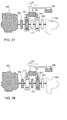
- Fig. 21 shows that the preferred embodiment of the system illustrated in Fig. 2 has the load the draw the secondary dynamo-electric unit to regenerate by reclaiming the kinetics so to charge the rechargeable device or to supply power to another load.
- Fig. 21 shows system function 19 provided by the preferred embodiment illustrated in Fig. 2, wherein, the system has the load to exercise the operation of a brake so to draw the secondary dynamo-electric unit to function as a generator for charging the rechargeable device or supplying power to another load.
- Fig. 22 shows that the preferred embodiment of the system illustrated in Fig. 2 has the load the draw both of the primary and the secondary dynamo-electric units to regenerate by reclaiming the kinetics so to charge the rechargeable device or to supply power to another load.
- Fig. 22 shows system function 20 provided by the preferred embodiment illustrated in Fig. 2, wherein, the system has the load to exercise the operation of a brake to draw both of the primary and the secondary dynamo-electric units to function as a generator for charging the rechargeable device or supplying power to another load.
- Fig. 23 shows that the preferred embodiment of the system illustrated in Fig. 2 exercises a braking on the load by means of a mechanical damper of the engine.
- Fig. 23 shows system function 21 provided by the preferred embodiment illustrated in Fig. 2, wherein, the engine has the damper to exercise the operation of brake on the load.
- Fig. 24 shows that the preferred embodiment of the system illustrated in Fig. 2 exercises a braking on the load by means of the mechanical damper of the engine and drives the primary dynamo-electric unit to regenerate for charging the rechargeable device or supplying power to another load.
- Fig. 24 shows system function 22 provided by the preferred embodiment illustrated in Fig. 2, wherein, the engine is used as the damper to exercise brake on the load while the primary dynamo-electric functions as a generator to regenerate by reclaiming the kinetics for regenerating so to charge the rechargeable device or to supply power to another load.
- Fig. 25 shows that the preferred embodiment of the system illustrated in Fig. 2 exercises a braking on the load by means of the mechanical damper of the engine and drives the secondary dynamo-electric unit to regenerate for charging the rechargeable device or supplying power to another load.
- Fig. 25 shows system function 23 provided by the preferred embodiment illustrated in Fig. 2, wherein, the secondary dynamo-electric unit functions as a generator to regenerate by reclaiming the kinetics for regenerating so to charge the rechargeable device or to supply power to another load.
- Fig. 26 shows that the preferred embodiment of the system illustrated in Fig. 2 exercises a braking on the load by means of the mechanical damper of the engine and drives both of the primary and the secondary dynamo-electric units to regenerate for charging the rechargeable device or supplying power to another load.
- Fig. 26 shows system function 24 provided by the preferred embodiment illustrated in Fig. 2, wherein, both of the primary and the secondary dynamo-electric units functioning as a generator to regenerate by reclaiming the kinetics so to charge the rechargeable device or to supply power to another load.
- Fig. 27 shows that the preferred embodiment of the system illustrated in Fig. 2 uses the power from the rechargeable device to drive the primary dynamo-electric unit to start the engine.
- Fig. 27 shows system function 25 provided by the preferred embodiment illustrated in Fig. 2, wherein, the power from the rechargeable device drives the primary dynamo-electric unit to function as a motor to start the engine.
- Fig. 28 shows that the preferred embodiment of the system illustrated in Fig. 2 uses the power from the rechargeable device to drive the secondary dynamo-electric unit to start the engine.
- Fig. 28 shows system function 26 provided by the preferred embodiment illustrated in Fig. 2, wherein, the power from the rechargeable device drives the secondary dynamo-electric unit to function as a motor to start the engine.
- Fig. 29 shows that the preferred embodiment of the system illustrated in Fig. 2 uses the power from the rechargeable device to drive both of the primary and the secondary dynamo-electric units to start the engine.
- Fig. 29 shows system function 27 provided by the preferred embodiment illustrated in Fig. 2, wherein, the power from the rechargeable device drives both of the primary and the secondary dynamo-electric units to function as a motor to start the engine.
- the constant speed of the engine among those system functions described above is defined as the range of operation speed wherein the engine is running at lower fuel consumption but paid the operation region with comparatively higher fuel saving of comparatively higher output power so to reach the optimal brake specific fuel consumption.
- the series and parallel combined dual power system of the present invention has the engine as the active power with its essential structure and functions described as follows:
- the series and parallel combined dual power drive system of the present invention may be adapted with the optional rechargeable device 106, so to control the generation power when the rotation kinetics from the engine serving as the active rotation power source 100 drives the primary dynamo-electric unit 101 to serve as a generator, and further to charge the rechargeable device 106 in case of no-load, light load or at other proper time, or to supply power to another power driven load 130.
- Functions provided by the system include:
- each of all the units may be arranged as required.
- Each unit may be made into a standing alone unit as required before being coupled to another unit; or as required, two or more than two units of the system may be made by sharing the same structure in various arrangements depending on the spatial conditions and other factors including heat dissipation, noise, manageability, and service.
- Fig. 30 shows that the preferred embodiment of the system illustrated in Fig. 2 is not adapted with a clutch between the output end and the load. As illustrated in Fig. 30, the clutch 112 is not adapted to where between the output end and the load side of the system. If the input end of the load is adapted with a clutch, the variable transmission dose not provide idling shift function, and the secondary dynamo-electric unit 103 fails to function as a generator driven by the engine serving as the active power source 100 of the system, nor as a motor to start the engine as illustrated in Fig. 2.
- the system may be selected to provide system functions 1 ⁇ 15, and all or any part of system functions 18 ⁇ 15 listed in Table B. Those system functions listed in Table B are illustrated in Figs. 31 ⁇ 53.
- Fig. 31 shows that the preferred embodiment of the system illustrated in Fig. 30 is adapted with the rechargeable unit to operate as the series combined power system with controllable engine speed.
- Fig. 31 shows system function 1 provided by the preferred embodiment illustrated in Fig. 30, wherein, the rechargeable device is adapted to the system and the system engages in the series combined power operation to drive the load.
- Fig. 32 shows that the preferred embodiment of the system illustrated in Fig. 30 adapted with the rechargeable device operates as the series combined power system with the engine running at a constant speed.
- Fig. 32 shows system function 2 provided by the preferred embodiment illustrated in Fig. 30, wherein, the rechargeable device is adapted for the engine to run at a constant speed for driving the system to engage in the series combined power operation to drive the load.
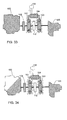
- Fig. 33 shows that the preferred embodiment of the system illustrated in Fig. 30 operate as the series combined power system with controllable engine speed without the adaptation of a rechargeable unit.
- Fig. 34 is a schematic view showing that the preferred embodiment of the system illustrated in Fig. 30 operate as the series combined power system with the engine running at constant speed without the adaptation of a rechargeable unit.
- Fig. 34 shows system function 4 provided by the preferred embodiment illustrated in Fig. 30, wherein, no rechargeable device is adapted to the system, and the engine runs at a constant speed to drive the system to engage in the series combined power operation for driving the load.
- Fig. 35 shows that the preferred embodiment of the system illustrated in Fig. 30 operates on the power from the engine to drive the load.
- Fig. 35 shows system function 5 provided by the preferred embodiment illustrated in Fig. 35, wherein, the system has the engine to drive the load.
- Fig. 36 shows that the preferred embodiment of the system illustrated in Fig. 30 operates on the power from the engine to jointly drive the load with both of the primary and the secondary dynamo-electric units driven by the rechargeable device.
- Fig. 36 shows system function 6 by the preferred embodiment illustrated in Fig. 30, wherein, the power from the engine and both of the primary and the secondary dynamo-electric units driven by the rechargeable device function as a motor in case of a heavy load to jointly drive the load.
- Fig. 37 shows that the preferred embodiment of the system illustrated in Fig. 30 operates on the power from the engine to jointly drive the load with the primary dynamo-electric unit driven by the rechargeable device.
- Fig. 37 shows system function 7 provided by the preferred embodiment illustrated in Fig. 30, wherein, in case of a heavy load, it is jointly driven by the power from the engine and both of the primary and the secondary dynamo-electric units functioning as a motor.
- Fig. 38 shows that the preferred embodiment of the system illustrated in Fig. 30 operates on the power from the engine to jointly drive the load with the secondary dynamo-electric unit driven by the rechargeable device.
- Fig. 38 shows system function 8 provided by the preferred embodiment illustrated in Fig 30, wherein, in case of a heavy load, the power from the engine and the secondary dynamo-electric unit driven by the rechargeable device functions a motor to jointly drive the load.
- Fig. 39 shows that the preferred embodiment of the system illustrated in Fig. 30 operates on the power from the engine to drive the load, and drive the primary dynamo-electric unit to function as a generator to charge the rechargeable device or supply power to another load.
- Fig. 39 shows system function 9 provided by the preferred embodiment illustrated in Fig. 30, wherein, the power from the engine drives the load and the primary dynamo-electric unit to function as a generator for charging the rechargeable device or supplying power to another load.
- Fig. 40 shows that the preferred embodiment of the system illustrated in Fig. 30 operates on the power from the engine to drive the load, and drive the secondary dynamo-electric unit to function as a generator to charge the rechargeable device or supply power to another load.
- Fig. 40 shows system function 10 provided by the preferred embodiment illustrated in Fig. 30, wherein, the power from the engine drives the load and the secondary dynamo-electric unit to function as a generator for charging the rechargeable device or supplying power to another load.
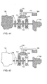
- Fig. 41 shows that the preferred embodiment of the system illustrated in Fig. 30 operates on the power from the engine to drive the load, and drive both of the primary and the secondary dynamo-electric units to function as a generator to charge the rechargeable device or supply power to another load.
- Fig. 41 shows system function 11 provided by the preferred embodiment illustrated in Fig. 30, wherein, the power from the engine drives the load and both of the primary and the secondary dynamo-electric units to function as a generator for charging the rechargeable device or supplying power to another load.
- Fig. 42 shows that the preferred embodiment of the system illustrated in Fig. 30 operates on the power from the rechargeable device to drive the primary dynamo-electric unit to further drive the load.
- Fig. 42 shows system function 12 provided by the preferred embodiment illustrated in Fig. 30, wherein, the power form the rechargeable device drives the primary dynamo-electric unit to function as a motor for driving the load.
- Fig. 43 shows that the preferred embodiment of the system illustrated in Fig. 30 operates on the power from the rechargeable device to drive the secondary dynamo-electric unit to further drive the load.
- Fig. 43 shows system function 13 provided by the preferred embodiment illustrated in Fig. 30, wherein, the power form the rechargeable device drives the secondary dynamo-electric unit to function as a motor for driving the load.
- Fig. 44 shows that the preferred embodiment of the system illustrated in Fig. 30 operates on the power from the rechargeable device to drive both of the primary and the secondary dynamo-electric units to further drive the load.
- Fig. 44 shows system function 14 provided by the preferred embodiment illustrated in Fig. 30, wherein, the power form the rechargeable device drives both of the primary and the secondary dynamo-electric units to function as a motor for driving the load.
- Fig. 45 shows that the preferred embodiment of the system illustrated in Fig. 30 has the engine to run at constant speed for driving the primary dynamo-electric unit to function as a generator to charge the rechargeable device or to supply power to another load.
- Fig. 45 shows system function 15 provided by the preferred embodiment illustrated in Fig. 30, wherein, the engine runs at a constant speed to drive the primary dynamo-electric unit to function as a generator to charge the rechargeable device or to supply power to another load.
- Fig. 46 shows that the preferred embodiment of the system illustrated in Fig. 30 has the load to drive the primary dynamo-electric unit to regenerate by reclaiming the kinetics r so to charge the rechargeable device or to supply power to another load.
- Fig. 46 shows system function 18 provided by the preferred embodiment illustrated in Fig. 30, wherein, the system has the load to exercise the operation of a brake thus to draw the primary dynamo-electric unit to function as a generator for charging the rechargeable device or supplying power to another load.
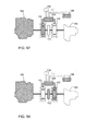
- Fig. 47 shows that the preferred embodiment of the system illustrated in Fig. 30 has the load to drive the secondary dynamo-electric unit to regenerate by reclaiming the kinetics so to charge the rechargeable device or to supply power to another load.
- Fig. 47 shows system function 19 provided by the preferred embodiment illustrated in Fig. 30, wherein, the system has the load to exercise the operation of a brake thus to draw the secondary dynamo-electric unit to function as a generator for charging the rechargeable device or supplying power to another load.
- Fig. 48 shows that the preferred embodiment of the system illustrated in Fig. 30 has the load to drive both of the primary and the secondary dynamo-electric units to regenerate by reclaiming the kinetics so to charge the rechargeable device or to supply power to another load.
- Fig. 48 shows system function 20 provided by the preferred embodiment illustrated in Fig. 30, wherein, the system has the load to exercise the operation of a brake thus to draw both of the primary and the secondary dynamo-electric units to function as a generator for charging the rechargeable device or supplying power to another load.
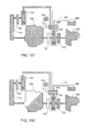
- Fig. 49 shows that the preferred embodiment of the system illustrated in Fig. 30 has the mechanical damper from the engine to exercise a brake to the load.
- Fig. 49 shows system function 21 provided by the preferred embodiment illustrated in Fig. 30, wherein, the mechanical damper from the engine exercises the braking operation on the load.
- Fig. 50 shows that the preferred embodiment of the system illustrated in Fig. 30 has the mechanical damper from the engine to exercise a brake on the load and to drive the primary dynamo-electric unit to regenerate for charging the rechargeable device or supplying power to another load.
- Fig. 50 shows system function 22 provided by the preferred embodiment illustrated in Fig. 30, wherein, the mechanical damper from the engine exercises the braking operation on the load while the primary dynamo-electric unit operates as a motor to regenerate by reclaiming the kinetics to charge the rechargeable device or to supply power to another load.
- Fig. 51 shows that the preferred embodiment of the system illustrated in Fig. 30 has the mechanical damper from the engine to exercise a brake on the load and to drive the secondary dynamo-electric unit to regenerate for charging the rechargeable device or supplying power to another load.
- Fig. 51 shows system function 23 provided by the preferred embodiment illustrated in Fig. 30, wherein, the mechanical damper from the engine exercises the braking operation on the load while the secondary dynamo-electric unit operates as a motor to regenerate by reclaiming the kinetics to charge the rechargeable device or to supply power to another load.
- Fig. 52 shows that the preferred embodiment of the system illustrated in Fig. 30 has the mechanical damper from the engine to exercise a brake on the load and to drive both of the primary and the secondary dynamo-electric units to regenerate for charging the rechargeable device or supplying power to another load.
- Fig. 52 shows system function 24 provided by the preferred embodiment illustrated in Fig. 30, wherein, the mechanical damper from the engine exercises the braking operation on the load while both of the primary and the secondary dynamo-electric units function as a motor to regenerate by reclaiming the kinetics to charge the rechargeable device or to supply power to another load.
- Fig. 53 shows that the preferred embodiment of the system illustrated in Fig. 30 operates on the power from the rechargeable device to drive the primary dynamo-electric unit to start the engine.
- Fig. 53 shows system function 25 provided by the preferred embodiment illustrated in Fig. 30, wherein, the power from the rechargeable device drives the primary dynamo-electric unit to function as a motor to start the engine.
- Fig. 54 shows that no clutch is provided between an active rotation power source and the primary dynamo-electric unit of the preferred embodiment of the system illustrated in Fig. 2.
- no optional clutch 102 is provided at where between the engine serving as the active rotation power source 100 and the primary dynamo-electric unit 101; therefore, the primary dynamo-electric unit 101 does not function as a motor to drive the load as illustrated in Fig. 2, nor regenerates by reclaiming the kinetics to exercise the brake; instead, the system as selected provides all or any part of those system functions 1 ⁇ 11, 13, 15 ⁇ 17, 19, 21 ⁇ 27 as listed in Table C as illustrated in Figs. 55 ⁇ 77.
- Fig. 55 shows that the preferred embodiment of the system illustrated in Fig. 54 is adapted with the rechargeable unit to operate as the series combined power system with controllable engine running speed.
- Fig. 55 shows system function 1 provided by the preferred embodiment illustrated in Fig. 54, wherein, the rechargeable device is adapted to the system to engage in the series combined power operation to drive the load.
- Fig. 56 shows that the preferred embodiment of the system illustrated in Fig. 54 is adapted with the rechargeable unit to operate as the series combined power system with the engine running at constant speed.
- Fig. 56 shows system function 2 provided by the preferred embodiment illustrated in Fig. 54, wherein, the rechargeable device is adapted to the system and the engine runs at a constant speed to drive the system to engage in the series combined power operation for driving the load.
- Fig. 57 shows that the preferred embodiment of the system illustrated in Fig. 54 operates as the series combined power system with controllable engine running speed without the adaptation of the rechargeable device.
- Fig. 57 shows system function 3 provided by the preferred embodiment illustrated in Fig. 54, wherein, the system is not adapted with the rechargeable device and is engaging in the series combined power operation to drive the load.
- Fig. 58 shows that the preferred embodiment of the system illustrated in Fig. 54 operates as the series combined power system with the engine running at constant speed.
- Fig. 58 shows system function 4 provided by the preferred embodiment illustrated in Fig. 54, wherein, the system is not adapted with the rechargeable device and the engine runs at a constant speed to drive the system to engage in the series combined power operation for driving the load.
- Fig. 59 shows that the preferred embodiment of the system illustrated in Fig. 54 operated on the power form the engine to drive the load.
- Fig. 59 shows system function 5 provided by the preferred embodiment illustrated in Fig. 54, wherein, the system has the power from the engine to drive the load.
- Fig. 60 shows that the preferred embodiment of the system illustrated in Fig. 54 operates on the power from the engine to jointly drive the load with both of the primary and the secondary dynamo-electric units driven by the rechargeable device.
- Fig. 60 shows system function 6 provided by the preferred embodiment illustrated in Fig. 54, wherein, the power from the engine, and in case of a heavy load, both of the primary and the secondary dynamo-electric units driven by the rechargeable device functioning as a motor jointly drive the load
- Fig. 61 shows that the preferred embodiment of the system illustrated in Fig. 54 operates on the power from the engine to jointly drive the load with both of the primary dynamo-electric unit driven by the rechargeable device.
- Fig. 61 shows system function 7 provided by the preferred embodiment illustrated in Fig. 54, wherein, the system in case of a heavy load has the power from the engine and the primary dynamo-electric unit driven by the rechargeable device to function as a motor jointly drive the load.
- Fig. 62 shows that the preferred embodiment of the system illustrated in Fig. 54 operates on the power from the engine to jointly drive the load with both of the secondary dynamo-electric unit driven by the rechargeable device.
- Fig. 62 shows system function 8 provided by the preferred embodiment illustrated in Fig. 54, wherein, the system in case of a heavy load has the power from the engine and the secondary dynamo-electric unit driven by the rechargeable device to function as a motor jointly drive the load.
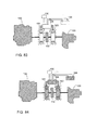
- Fig. 63 shows that the preferred embodiment of the system illustrated in Fig. 54 operates on the power from the engine to drive the load and to drive the primary dynamo-electric unit to function as a generator for charging the rechargeable device or supplying power to another load.
- Fig. 63 shows system function 9 provided by the preferred embodiment illustrated in Fig. 54, wherein, the power from the engine drives the load and the primary dynamo-electric unit to function as a generator for charging the rechargeable device or supplying power to another load.
- Fig. 64 shows that the preferred embodiment of the system illustrated in Fig. 54 operates on the power from the engine to drive the load and to drive the secondary dynamo-electric unit to function as a generator for charging the rechargeable device or supplying power to another load.
- Fig. 64 shows system function 10 provided by the preferred embodiment illustrated in Fig. 54, wherein, the power from the engine drives the load and the secondary dynamo-electric unit to function as a generator for charging the rechargeable device or supplying power to another load.
- Fig. 65 shows that the preferred embodiment of the system illustrated in Fig. 54 operates on the power from the engine to drive the load and to drive both of the primary and the secondary dynamo-electric units to function as a generator for charging the rechargeable device or supplying power to another load.
- Fig. 65 shows system function 11 provided by the preferred embodiment illustrated in Fig. 54, wherein, the power from the engine drives the load and both of the primary and the secondary dynamo-electric units to function as a generator for charging the rechargeable device or supplying power to another load.
- Fig. 66 shows that the preferred embodiment of the system illustrated in Fig. 54 has the power from the rechargeable device to drive the secondary dynamo-electric unit to further drive the load.
- Fig. 66 shows system function 13 provided by the preferred embodiment illustrated in Fig. 54, wherein, the power from the rechargeable device drives the secondary dynamo-electric unit to function as a motor to drive the load.
- Fig. 67 shows that the preferred embodiment of the system illustrated in Fig. 54 has the engine running at constant speed to drive the primary dynamo-electric unit to function as a generator for charging the rechargeable device or supplying power to another load.
- Fig. 66 shows system function 15 provided by the preferred embodiment illustrated in Fig. 54, wherein, the power from the rechargeable device drives the primary dynamo-electric unit to function as a motor to drive the load.
- Fig. 68 shows that the preferred embodiment of the system illustrated in Fig. 54 has the engine running at constant speed to drive the secondary dynamo-electric unit to function as a generator for charging the rechargeable device or supplying power to another load.
- Fig. 68 shows system function 16 provided by the preferred embodiment illustrated in Fig. 54, wherein, the engine runs at a constant speed to drive the secondary dynamo-electric unit to function as a generator for charging the rechargeable device or supplying power to another load.
- Fig. 69 shows that the preferred embodiment of the system illustrated in Fig. 54 has the engine running at constant speed to drive both of the primary and the secondary dynamo-electric units to function as a generator for charging the rechargeable device or supplying power to another load.
- Fig. 69 shows system function 17 provided by the preferred embodiment illustrated in Fig. 54, wherein, the engine runs at a constant speed to drive both of the primary and the secondary dynamo-electric units to function as a generator for charging the rechargeable device or supplying power to another load.
- Fig. 70 shows that the preferred embodiment of the system illustrated in Fig. 54 has the load to draw the secondary dynamo-electric unit to regenerate by reclaiming the kinetics so to chare the rechargeable device or to supply power to another load.
- Fig. 70 shows system function 19 provided by the preferred embodiment illustrated in Fig. 54, wherein, the system has the load to exercise the braking operation to draw the secondary dynamo-electric unit to function as a generator for charging the rechargeable device or supplying power to another load.
- Fig. 71 shows that the preferred embodiment of the system illustrated in Fig. 54 has the mechanical damper of the engine to exercise a brake on the load.
- Fig. 71 show system function 21 provided by the preferred embodiment illustrated in Fig. 54, wherein, the mechanical damper from the engine exercises the braking operation on the load.
- Fig. 72 shows that the preferred embodiment of the system illustrated in Fig. 54 has the mechanical damper of the engine to exercise a brake on the load and to drive the primary dynamo-electric unit to regenerate for charging the rechargeable device or supplying power to another load.
- Fig. 72 shows system function 22 provided by the preferred embodiment illustrated in Fig. 54, wherein, mechanical damper of the engine exercises the braking operation on the load while the primary dynamo-electric unit functions as a generator to regenerate by reclaiming the kinetics so to charge the rechargeable device or to supply power to another load.
- Fig. 73 shows that the preferred embodiment of the system illustrated in Fig. 54 has the mechanical damper of the engine to exercise a brake on the load and to drive the secondary dynamo-electric unit to regenerate for charging the rechargeable device or supplying power to another load.
- Fig. 73 shows system function 23 provided by the preferred embodiment illustrated in Fig. 54, wherein, mechanical damper of the engine exercises the braking operation on the load while the secondary dynamo-electric unit functions as a generator to regenerate by reclaiming the kinetics so to charge the rechargeable device or to supply power to another load.
- Fig. 74 shows that the preferred embodiment of the system illustrated in Fig. 54 has the mechanical damper of the engine to exercise a brake on the load and to drive both of the primary and the secondary dynamo-electric units to regenerate for charging the rechargeable device or supplying power to another load.
- Fig. 74 shows system function 24 provided by the preferred embodiment illustrated in Fig. 54, wherein, mechanical damper of the engine exercises the braking operation on the load while both of the primary and the secondary dynamo-electric units functions as a generator to regenerate by reclaiming the kinetics so to charge the rechargeable device or to supply power to another load.
- Fig. 75 shows that the preferred embodiment of the system illustrated in Fig. 54 operates on the power from the rechargeable device to drive the primary dynamo-electric unit to start the engine.
- Fig. 75 shows system function 25 provided by the preferred embodiment illustrated in Fig. 54, wherein, the power from the rechargeable device drives the primary dynamo-electric unit to function as a motor for starting the engine.
- Fig. 76 shows that the preferred embodiment of the system illustrated in Fig. 54 operates on the power from the rechargeable device to drive the secondary dynamo-electric unit to start the engine.
- Fig. 76 shows system function 26 provided by the preferred embodiment illustrated in Fig. 54, wherein, the power from the rechargeable device drives the secondary dynamo-electric unit to function as a motor for starting the engine.
- Fig. 77 shows that the preferred embodiment of the system illustrated in Fig. 54 operates on the power from the rechargeable device to drive both of the primary and the secondary dynamo-electric units to start the engine.
- Fig. 77 shows system function 27 provided by the preferred embodiment illustrated in Fig. 54, wherein the power from the rechargeable device drives both of the primary and the secondary dynamo-electric units to function as a motor for starting the engine.
- Fig. 78 is a schematic view showing that the preferred embodiment of the system illustrated in Fig. 2 is not adapted with a clutch either between the output end and the load side, or between the active rotation power source and the primary dynamo-electric unit.
- the system may provide all or any part of system functions 1 ⁇ 11, 13, 15, 19, and 21 ⁇ 25 of those functions listed in Table D. Figs. 79 ⁇ 99 show those system functions listed in Table D.
- Fig. 79 shows that the preferred embodiment of the system illustrated in Fig. 78 adapted with the rechargeable device operates as the series combine power system with controllable engine speed.
- Fig. 79 shows system function 1 provided by the preferred embodiment illustrated in Fig. 78, wherein, the rechargeable device is adapted to the system for the system to engage in the series combined power operation for driving the load.
- Fig. 80 shows that the preferred embodiment of the system illustrated in Fig. 78 adapted with the adaptation of the rechargeable device operates as the series combined power system at a constant engine speed.
- Fig. 80 shows system function 2 provided by the preferred embodiment illustrated in Fig. 78, wherein, the rechargeable device is adapted to the system, and the engine runs at a constant speed to drive the system to engage in the series combined power operation for driving the load.
- Fig. 81 shows that the preferred embodiment of the system illustrated in Fig. 78 not adapted with the adaptation of the rechargeable device operates as the series combined power system with controllable engine speed.
- Fig. 81 shows system function 3 provided by the preferred embodiment illustrated in Fig. 78, wherein, the system is not adapted with the rechargeable device and is engaging in the series combined power operation to drive the load.
- Fig. 82 shows that the preferred embodiment of the system illustrated in Fig. 78 not adapted with the adaptation of the rechargeable device operates as the series combined power system at a constant engine speed.
- Fig. 82 shows system function 4 provided by the preferred embodiment illustrated in Fig. 78, wherein, the system is not adapted with the rechargeable device, and the engine runs at a constant speed to drive the system to engage in the series combined power operation for driving the load.
- Fig. 83 shows that the preferred embodiment of the system illustrated in Fig. 78 operates on the engine power to drive the load.
- Fig. 83 shows system function 5 provided by the preferred embodiment illustrated in Fig. 78, wherein, the system has the power from the engine to drive the load.
- Fig. 84 shows that the preferred embodiment of the system illustrated in Fig. 78 operates on the power form the engine to jointly drive the load with both of the primary and the secondary dynamo-electric units driven by the rechargeable device.
- Fig. 84 shows system function 6 provided by the preferred embodiment illustrated in Fig. 78, wherein, the system in case of a heavy load has the power form the engine and both of the primary and the secondary dynamo-electric units driven by the rechargeable device to function as a motor for jointly driving the load.
- Fig. 85 shows that the preferred embodiment of the system illustrated in Fig. 78 operates on the power form the engine to jointly drive the load with the primary dynamo-electric unit driven by the rechargeable device.
- Fig. 85 shows system function 7 provided by the preferred embodiment illustrated in Fig. 78, wherein, the system in case of a heavy load has the power form the engine and the primary dynamo-electric unit driven by the rechargeable device to function as a motor for jointly driving the load.
- Fig. 86 shows that the preferred embodiment of the system illustrated in Fig. 78 operates on the power form the engine to jointly drive the load with the secondary dynamo-electric unit driven by the rechargeable device.
- Fig. 86 shows system function 8 provided by the preferred embodiment illustrated in Fig. 78, wherein, the system in case of a heavy load has the power form the engine and the secondary dynamo-electric units driven by the rechargeable device to function as a motor for jointly driving the load.
- Fig. 87 shows that the preferred embodiment of the system illustrated in Fig. 78 operates on the power from the engine to drive the load, and to drive the primary dynamo-electric unit to function as a generator to charge the rechargeable device or to supply power to another load.
- Fig. 87 shows system function 9 provided by the preferred embodiment illustrated in Fig. 78, wherein, the power from the engine drives the load and the primary dynamo-electric unit to function as a generator for charging the rechargeable device or supplying power to another load.
- Fig. 88 shows that the preferred embodiment of the system illustrated in Fig. 78 operates on the power from the engine to drive the load, and to drive the secondary dynamo-electric unit to function as a generator to charge the rechargeable device or to supply power to another load.
- Fig. 88 shows system function 10 provided by the preferred embodiment illustrated in Fig. 78, wherein, the power from the engine drives the load and the secondary dynamo-electric unit to function as a generator for charging the rechargeable device or supplying power to another load.
- Fig. 89 shows that the preferred embodiment of the system illustrated in Fig. 78 operates on the power from the engine to drive the load, and to drive both of the primary and the secondary dynamo-electric units to function as a generator to charge the rechargeable device or to supply power to another load.
- Fig. 89 shows system function 11 provided by the preferred embodiment illustrated in Fig. 78, wherein, the power from the engine drives the load and both of the primary and the secondary dynamo-electric units to function as a generator for charging the rechargeable device or supplying power to another load.
- Fig. 90 shows that the preferred embodiment of the system illustrated in Fig. 78 operates on the power from the rechargeable device to drive the secondary dynamo-electric unit for driving the load.
- Fig. 90 shows system function 13 provided by the preferred embodiment illustrated in Fig. 78, wherein, the power from the rechargeable device drives the secondary dynamo-electric unit to function as a motor for driving the load.
- Fig. 91 shows that the preferred embodiment of the system illustrated in Fig. 78 operates on the power from the rechargeable device to drive the primary dynamo-electric unit for driving the load.
- Fig. 91 shows system function 15 provided by the preferred embodiment illustrated in Fig. 78, wherein, the engine runs at a constant speed to drive the primary dynamo-electric unit to function as a generator for charging the rechargeable device or supplying power to another load.
- Fig. 92 shows that the preferred embodiment of the system illustrated in Fig. 78 has the load to draw the secondary dynamo-electric unit to regenerate by reclaiming the kinetics for charging the rechargeable device or supplying power to another load.
- Fig. 92 shows system function 19 provided by the preferred embodiment illustrated in Fig. 78, wherein, the system has the load to exercise the braking operation to draw the secondary dynamo-electric unit to function as a generator for charging the rechargeable device and supplying power to another load.
- Fig. 93 shows that the preferred embodiment of the system illustrated in Fig. 78 operates on the mechanical damper of the engine to exercise a brake on the load.
- Fig. 93 shows system function 21 provided by the preferred embodiment illustrated in Fig. 78, wherein, the mechanical damper from the engine exercise the braking operation on the load.
- Fig. 94 shows that the preferred embodiment of the system operates on the mechanical damper of the engine to exercise a brake on the load and to drive the primary dynamo-electric unit to regenerate for charging the rechargeable device or supplying power to another load.
- Fig. 94 shows system function 22 provided by the preferred embodiment illustrated in Fig. 78, wherein, the mechanical damper of the engine exercises the braking operation on the load, meanwhile the primary dynamo-electric unit functions as a generator to regenerate by reclaiming the kinetics so to charge the rechargeable device or to supply power to another load.
- Fig. 95 shows that the preferred embodiment of the system operates on the mechanical damper of the engine to exercise a brake on the load and to drive the secondary dynamo-electric unit to regenerate for charging the rechargeable device or supplying power to another load.
- Fig. 95 shows system function 23 provided by the preferred embodiment illustrated in Fig. 78, wherein, the mechanical damper of the engine exercises the braking operation on the load, meanwhile the secondary dynamo-electric unit functions as a generator to regenerate by reclaiming the kinetics so to charge the rechargeable device or to supply power to another load.
- Fig. 96 shows that the preferred embodiment of the system operates on the mechanical damper of the engine to exercise a brake on the load and to drive both of the primary and the secondary dynamo-electric units to regenerate for charging the rechargeable device or supplying power to another load.
- Fig. 96 shows system function 24 provided by the preferred embodiment illustrated in Fig. 78, wherein, the mechanical damper of the engine exercises the braking operation on the load, meanwhile both of the primary and the secondary dynamo-electric units function as a generator to regenerate by reclaiming the kinetics so to charge the rechargeable device or to supply power to another load.
- Fig. 97 shows that the preferred embodiment of the system illustrated in Fig. 78 operates on the power form the rechargeable device to drive the primary dynamo-electric unit to start the engine.
- Fig. 97 shows system function 25 provided by the preferred embodiment illustrated in Fig. 78, wherein, the power from the rechargeable device drives the primary dynamo-electric unit to function as a motor to start the engine.
- Fig. 98 shows that the preferred embodiment of the system illustrated in Fig. 78 operates on the power form the rechargeable device to drive the secondary dynamo-electric unit to start the engine.
- Fig. 98 shows system function 26 provided by the preferred embodiment illustrated in Fig. 78, wherein, the power from the rechargeable device drives the secondary dynamo-electric unit to function as a motor to start the engine.
- Fig. 99 shows that the preferred embodiment of the system illustrated in Fig. 78 operates on the power form the rechargeable device to drive both of the primary and the secondary dynamo-electric units to start the engine.
- Fig. 97 shows system function 27 provided by the preferred embodiment illustrated in Fig. 78, wherein, the power from the rechargeable device drives both of the primary and secondary dynamo-electric units to function as a motor to start the engine.
- Fig. 100 is a schematic view showing that the preferred embodiment of the system illustrated in Fig. 2 has the primary dynamo-electric unit to be independently and directly driven by the active rotation power source or through a transmission device.
- the system has the engine serving as the active rotation power source 100 directly driven by the primary dynamo-electric unit 101 alone or through the transmission 119 or the clutch 102; the output end of the active rotation power source 100 is directly or through a transmission unit 109 and the clutch 112 coupled to the secondary dynamo-electric unit 103; thereby, the output end of the secondary dynamo-electric unit 103 is coupled to the load 120 through the clutch 122.
- the primary dynamo-electric unit 101 may function as a generator and a motor as required, or only as a generator. Accordingly, the primary dynamo-electric fails to function as the motor to drive the load 120 or to function alone to regenerate by reclaiming kinetics to exercise brake on the load 120within the configuration as illustrated in Fig. 2.
- the system may provide all or any part of those system functions 1 ⁇ 11, 13, 15 ⁇ 17, 19 and 21 ⁇ 27 as listed in Table E.
- Figs. 101 ⁇ 123 show those functions listed in Table E.
- Fig. 101 shows that the preferred embodiment of the system illustrated in Fig. 100 adapted with the rechargeable device functions as the series combined power system with controllable engine speed.
- Fig. 101 shows system function 1 provided by the preferred embodiment illustrated in Fig. 100, wherein, the system is adapted with the rechargeable device to engage in the series combined power operation to drive the load.
- Fig. 102 shows that the preferred embodiment of the system illustrated in Fig. 100 adapted with the rechargeable device functions as the series combined power system at a constant engine speed.
- Fig. 102 shows system function 2 provided by the preferred embodiment illustrated in Fig. 100, wherein, the rechargeable device is adapted to the system and the engine runs at a constant speed to drive the system to engage in the operation of series combined power for driving the load.
- Fig. 103 shows that the preferred embodiment of the system illustrated in Fig. 100 not adapted with the rechargeable device functions as the series combined power system with controllable engine speed.
- Fig. 103 shows system function 3 provided by the preferred embodiment illustrated in Fig. 100, wherein, the system is not adapted with the rechargeable device and is engaged in the operation of the series combined power for driving the load.
- Fig. 104 shows that the preferred embodiment of the system illustrated in Fig. 100 not adapted with the rechargeable device functions as the series combined power system at a constant engine speed.
- Fig. 104 shows system function 4 provided by the preferred embodiment illustrated in Fig. 100, wherein, the system is not adapted with the rechargeable device, and the engine runs at a constant speed to drive the system to engage in the operation of the series combined power for driving the load.
- Fig. 105 shows that the preferred embodiment of the system illustrated in Fig. 100 operates on the power form the engine to drive the load.
- Fig. 105 shows system function 5 provided by the preferred embodiment illustrated in Fig. 100, wherein, the system has the power from the engine to drive the load.
- Fig. 106 shows that the preferred embodiment of the system illustrated in Fig. 100 operates on the power from the engine to jointly drive the load with both of the primary and the secondary dynamo-electric units driven by the rechargeable device.
- Fig. 106 shows system function 6 provided by the preferred embodiment illustrated in Fig. 100, wherein, the system, in case of a heavy load, has the power form the engine, and the primary and the secondary dynamo-electric units driven by the rechargeable device to function as a motor to jointly drive the load.
- Fig. 107 shows that the preferred embodiment of the system illustrated in Fig. 100 operates on the power from the engine to jointly drive the load with the primary dynamo-electric unit driven by the rechargeable device.
- Fig. 107 shows system function 7 provided by the preferred embodiment illustrated in Fig. 100, wherein, the system, in case of a heavy load, has the power form the engine, and the primary dynamo-electric unit driven by the rechargeable device to function as a motor to jointly drive the load.
- Fig. 108 is a schematic view showing that the preferred embodiment of the system illustrated in Fig. 100 operates on the power from the engine to jointly drive the load with the secondary dynamo-electric unit driven by the rechargeable device.
- Fig. 108 shows system function 8 provided by the preferred embodiment illustrated in Fig. 100, wherein, the system, in case of a heavy load, has the power form the engine, and the secondary dynamo-electric unit driven by the rechargeable device to function as a motor to jointly drive the load.
- Fig. 109 shows that the preferred embodiment of the system illustrated in Fig. 100 operates on the power of the engine to drive the load, and to drive the primary dynamo-electric unit to function as a generator to charge the rechargeable device or to supply power to another load.
- Fig. 109 shows system function 9 provided by the preferred embodiment illustrated in Fig. 100, wherein, the power from the engine drives the load and the primary dynamo-electric unit to function as a generator for charging the rechargeable device or supplying power to another load.
- Fig. 110 shows that the preferred embodiment of the system illustrated in Fig. 100 operates on the power of the engine to drive the load, and to drive the secondary dynamo-electric unit to function as a generator to charge the rechargeable device or to supply power to another load.
- Fig. 110 shows system function 10 provided by the preferred embodiment illustrated in Fig. 100, wherein, the power from the engine drives the load and the secondary dynamo-electric unit to function as a generator for charging the rechargeable device or supplying power to another load.
- Fig. 111 is a schematic view showing that the preferred embodiment of the system illustrated in Fig. 100 operates on the power of the engine to drive the load, and to drive both of the primary and the secondary dynamo-electric units to function as a generator to charge the rechargeable device or to supply power to another load.
- Fig. 111 shows system function 11 provided by the preferred embodiment illustrated in Fig. 100, wherein, the power from the engine drives the load and both of the primary and the secondary dynamo-electric units to function as a generator for charging the rechargeable device or supplying power to another load.
- Fig. 112 is a schematic view showing that the preferred embodiment of the system illustrated in Fig. 100 operates on the power from the rechargeable device to drive the secondary dynamo-electric unit for driving the load.
- Fig. 112 shows system function 13 provided by the preferred embodiment illustrated in Fig. 100, wherein, the power from the rechargeable device drives the secondary dynamo-electric unit to function as a motor for driving the load.
- Fig. 113 shows that the preferred embodiment of the system illustrated in Fig. 100 operates with the engine running at a constant speed to drive the primary dynamo-electric unit to function as a generator to charge the rechargeable device or to supply power to another load.
- Fig. 113 shows system function 15 provided by the primary dynamo-electric unit to function as a generator for charging the rechargeable device or supplying power to another load.
- Fig. 114 shows that the preferred embodiment of the system illustrated in Fig. 100 operates with the engine running at a constant speed to drive the secondary dynamo-electric unit to function as a generator to charge the rechargeable device or to supply power to another load.
- Fig. 114 shows system function 16 provided by the preferred embodiment illustrated in Fig. 100, wherein, Fig. 114 shows system function 16 provided by the preferred embodiment illustrated in Fig. 100, wherein, the engine runs at a constant speed to drive the secondary dynamo-electric unit to function as a generator for charging the rechargeable device or supplying power to another load.
- Fig. 115 shows that the preferred embodiment of the system illustrated in Fig. 100 operates with the engine running at a constant speed to drive both of the primary and the secondary dynamo-electric units to function as a generator to charge the rechargeable device or to supply power to another load.
- Fig. 115 shows system function 17 of the preferred embodiment illustrated in Fig. 100, wherein, the engine runs at a constant speed to drive both of the primary and the secondary dynamo-electric units to function as a generator for charging the rechargeable device or supplying power to another load.
- Fig. 116 shows that the preferred embodiment of the system illustrated in Fig. 100 has the load to draw the secondary dynamo-electric unit to regenerate by reclaiming the kinetics for charging the rechargeable device or supplying power to another load.
- Fig. 116 shows system function 19 provided by the preferred embodiment illustrated in Fig. 100, wherein, the system has the load to exercise the braking operation to draw the secondary dynamo-electric unit to function as a generator for charging the rechargeable device or supplying power to another load.
- Fig. 117 shows that the preferred embodiment of the system illustrated in Fig. 100 has the mechanical damper of the engine to exercise the brake on the load.
- Fig. 117 shows system function 21 provided by the preferred embodiment illustrated in Fig. 100, wherein, the mechanical damper from the engine exercises the braking operation on the load.
- Fig. 118 shows that the preferred embodiment of the system illustrated in Fig. 100 has the mechanical damper of the engine to exercise a brake on the load and to drive the primary dynamo-electric unit to regenerate for charging the rechargeable device or supplying power to another load.
- Fig. 118 shows system function 22 provided by the preferred embodiment illustrated in Fig. 100, wherein, the mechanical damper from the engine exercise the braking operation on the load, meanwhile, the primary dynamo-electric unit functions as a generator to regenerate by reclaiming kinetics for charging the rechargeable device or supplying power to another load.
- Fig. 119 shows that the preferred embodiment of the system illustrated in Fig. 100 has the mechanical damper of the engine to exercise a brake on the load and to drive the secondary dynamo-electric unit to regenerate for charging the rechargeable device or supplying power to another load.
- Fig. 119 shows system function 23 provided by the preferred embodiment illustrated in Fig. 100, wherein, he mechanical damper from the engine exercise the braking operation on the load, meanwhile, the secondary dynamo-electric unit functions as a generator to regenerate by reclaiming kinetics for charging the rechargeable device or supplying power to another load.
- Fig. 120 is a schematic view showing that the preferred embodiment of the system illustrated in Fig. 100 has the mechanical damper of the engine to exercise a brake on the load and to drive both of the primary and the secondary dynamo-electric units to regenerate for charging the rechargeable device or supplying power to another load.
- Fig. 120 shows system function 24 provided by the preferred embodiment illustrated in Fig. 100, wherein, the mechanical damper from the engine exercise the braking operation on the load, meanwhile, the primary and the secondary dynamo-electric units function as a generator to regenerate by reclaiming kinetics for charging the rechargeable device or supplying power to another load.
- Fig. 121 is a schematic view showing that the preferred embodiment of the system illustrated in Fig. 100 operates on the power from the rechargeable device to drive the primary dynamo-electric unit to start the engine.
- Fig. 121 shows system function 25 provided by the preferred embodiment illustrated in Fig. 100, wherein, power from the rechargeable device drives the primary dynamo-electric unit to function as a motor to start the engine.
- Fig. 122 is a schematic view showing that the preferred embodiment of the system illustrated in Fig. 100 operates on the power from the rechargeable device to drive the secondary dynamo-electric unit to start the engine.
- Fig. 122 shows system function 26 provided by the preferred embodiment illustrated in Fig. 100, wherein, power from the rechargeable device drives the secondary dynamo-electric unit to function as a motor to start the engine.
- Fig. 123 is a schematic view showing that the preferred embodiment of the system illustrated in Fig. 100 operates on the power from the rechargeable device to drive both of the primary and the secondary dynamo-electric units to start the engine.
- Fig. 123 shows system function 27 provided by the preferred embodiment illustrated in Fig. 100, wherein, power from the rechargeable device drives both of the primary and the secondary dynamo-electric units to function as a motor to start the engine.
- Fig. 124 is a block chart showing that the preferred embodiment of the system illustrated in Fig. 1 has different layouts of spatial configuration among the constituent units without changing the mechanism of the system.
- the shaft of the engine and that of the secondary dynamo-electric unit are arranged in parallel.
- the structure illustrated is just for reference purpose while based on the mechanical principles illustrated in Figs. 1, 30, 54, 78 or 100, the number of the secondary dynamo-electric unit 103 may be less than, greater than or equal to that of the primary dynamo-electric unit 101 coupled to the same number of the clutch or the variable transmission unit for transmission.
- those multiple secondary dynamo-electric units 103 may individually or jointly drive the load.
- Fig. 125 is a schematic view showing that the preferred embodiment of the system illustrated in Fig. 1 engages in the distribution of power by a variable transmission unit driven by the active power source to drive in sequent two or more than two primary dynamo-electric units, clutches, and the secondary dynamo-electric units for driving the load.
- the variable transmission unit 109 adapted to the output end of the active rotation power source 100 is driven by the active rotation power source 100, the individual output end of the variable transmission unit 109 is provided to respectively drive two or more than two rear end loads same as those provided by the preferred embodiment illustrated in Fig. 1 including multiple primary dynamo-electric units, clutches 112, secondary dynamo-electric units 103 and related transmission units.
- the variable transmission 109 for power distribution may be provided in the form of semi-automatic, or manual variable transmission device, or one with fixed speed ratio, or a differential gear set, epicyclical gear set, or other variable transmission device of the prior art.
- Fig. 126 is a schematic view showing that the preferred embodiment of the system illustrated in Fig. 1 engages in the distribution of power by the variable transmission unit driven by an output end from the primary dynamo-electric unit to drive in sequent two or more than two clutches, and the secondary dynamo-electric units for respectively driving the load.
- the primary dynamo-electric unit 101 drives the variable transmission unit 109 adapted to the output end of the primary dynamo-electric unit 101.
- the individual output end of the variable transmission unit 109 is provided to respectively drive two or more than two rear end loads same as those provided by the preferred embodiment illustrated in Fig. 1 including multiple secondary dynamo-electric units, clutches 112, secondary dynamo-electric units 103 and related transmission units.
- the variable transmission 109 for power distribution may be provided in the form of semi-automatic, or manual variable transmission device, or one with fixed speed ratio, or a differential gear set, epicyclical gear set, or other variable transmission device of the prior art.
- Fig. 127 is a schematic view showing that the preferred embodiment of the system illustrated in Fig. 1 has the clutch driven by the primary dynamo-electric unit to drive the variable transmission unit for power distribution so to drive two or more than two secondary dynamo-electric units.
- the individual output end of the variable transmission unit 109 further driven by the clutch 112 driven by the primary dynamo-electric unit 101 is provided respectively to drive multiple rear end loads same as those provided by the preferred embodiment illustrated in Fig. 1 including multiple secondary dynamo-electric unit 103 and related transmission device.
- the variable transmission 109 for power distribution may be provided in the form of semi-automatic, or manual variable transmission device, or one with fixed speed ratio, or a differential gear set, epicyclical gear set, or other variable transmission device of the prior art.
- Fig. 128 is a schematic view showing that the preferred embodiment of the system illustrated in Fig. 1 has the variable unit at the output end of the system driven by the secondary dynamo-electric unit to engage in power distribution for driving two or more than two units of load.
- the individual output end of the system driven by the secondary dynamo-electric unit 103 is provided respectively to drive multiple rear end loads same as those provided by the preferred embodiment illustrated in Fig. 1 including multiple loads and related transmission device.
- the variable transmission 109 for power distribution may be provided in the form of semi-automatic, or manual variable transmission device, or one with fixed speed ratio, or a differential gear set, epicyclical gear set, or other variable transmission device of the prior art.
- Fig. 129 is a schematic view showing that the preferred embodiment of the system illustrated in Fig. 1 has the individual output end of the variable transmission unit further driven by the clutch driven by the primary dynamo-electric unit to be respectively coupled to the rotary part of the secondary dynamo-electric unit and to the load end.
- the output end of the clutch 112 driven by the primary dynamo-electric unit 101, the output end and the load end of the secondary dynamo-electric unit 103 are incorporated together by the variable transmission unit 109.
- the variable transmission 109 for power distribution may be provided in the form of semi-automatic, or manual variable transmission device, or one with fixed speed ratio, or a differential gear set, epicyclical gear set, or other variable transmission device of the prior art.
- Fig. 130 is a schematic view showing that the preferred embodiment of the system illustrated in Fig. 1 has the output from the active rotation power source to be respectively coupled to the primary dynamo-electric unit through the variable transmission unit driven by the active rotation power source, and coupled to the secondary dynamo-electric unit through the clutch.
- the rotation kinetics outputted by the active rotation power source 100 is directly or through the clutch 102 coupled to the primary dynamo-electric unit 101, and to the secondary dynamo-electric unit 103 through the clutch 112.
- the variable transmission 109 for power distribution may be provided in the form of semi-automatic, or manual variable transmission device, or one with fixed speed ratio, or a differential gear set, epicyclical gear set, or other variable transmission device of the prior art.
- Fig. 131 is a schematic view showing that the preferred embodiment of the system illustrated in Fig. 1 has the output from the active rotation power source respectively coupled through the variable transmission unit driven by the active rotation power source to the primary dynamo-electric unit, and through the clutch to the individual output end of the variable transmission unit driven by the clutch for respectively driving two or more than two units of the secondary dynamo-electric units and loads.
- the rotation kinetics outputted by the active rotation power source 100 may be directly coupled from the variable transmission unit 109 or through the clutch 102 to the primary dynamo-electric unit 101 and coupled to the variable transmission unit 109 through the clutch 112, together with the individual output end of the variable transmission unit 109 coupled through the clutch 112 to respectively drive multiple secondary dynamo-electric units 103 and loads.
- the variable transmission 109 for power distribution may be provided in the form of semi-automatic, or manual variable transmission device, or one with fixed speed ratio, or a differential gear set, epicyclical gear set, or other variable transmission device of the prior art.
- Fig. 132 is a schematic view showing that the preferred embodiment of the system illustrated in Fig. 1 has two output ends with one end coupled to the first primary dynamo-electric unit and the other end coupled to the variable transmission unit comprised of clutch and differential gear set to respectively drive the load through the clutch and the secondary dynamo-electric unit.
- one output end from the active rotation power source 100 is optionally provided with the clutch 102 and the variable transmission unit 109 to drive the primary dynamo-electric unit 101 while another output end of the active rotation power source 100 is optionally provided with the clutch 112 to respectively through the variable transmission unit 109 comprised of the differential gear set drive the individual secondary dynamo-electric unit 102 via the optionally provided clutch 1120, and to respectively directly or indirectly through the optionally provided variable transmission unit 109 to respectively drive the load 120.
- One or multiple primary dynamo-electric unit 101 may be driven by the active rotation power source 100; and one or multiple variable transmission unit 109 comprised of the clutch 112 and the differential gear set, the clutch 1120 adapted to the variable transmission unit 109, the secondary dynamo-electric unit 103, the variable transmission unit 109, and the load may be provided; and either or both of the clutch 112 and the clutch 1120 may be optionally provided.
- the clutch 112 or the clutch 1120 is disengaged while the active rotation power source 100 drives the primary dynamo-electric unit 101 to operate as a generator; the power so generated drives the secondary dynamo-electric unit 103 to operate as a motor for driving the load; and the clutch 112 or the clutch 1120 is closed up when the preferred embodiment executes various functions related to parallel combined power drive system.
- Fig. 133 is a schematic view showing that the preferred embodiment of the system illustrated in Fig. 1 has the rotary part of the primary dynamo-electric unit to be coupled to the secondary dynamo-electric unit, and that optionally the variable transmission unit is adapted to the secondary dynamo-electric unit to drive the load and another variable transmission unit is provided between the output of the active rotation power source and the rotary part of the primary dynamo-electric unit.
- the clutch 112 is provided between the rotary part of the primary dynamo-electric unit 101 and that of the secondary dynamo-electric unit 103; the variable transmission unit 109 is optionally provided between the rotary part of the secondary dynamo-electric unit 103 and the load 120; and the variable transmission unit 109 is provided between the rotary part of the active rotation power source 100 and that of the primary dynamo-electric unit 101.
- the clutch 112 When the preferred embodiment executes various functions related to the series combined power drive system, the clutch 112 is disengaged while the active rotation power source 100 drives the primary dynamo-electric unit 101 to operate as a generator; the power so generated drives the secondary dynamo-electric unit 103 to operate as a motor for driving the load; and the clutch 112 is closed up when the preferred embodiment executes various functions related to parallel combined power drive system.
- Fig. 134 is a schematic view showing that the preferred embodiment of the system illustrated in Fig. 12 has the rotary part of the active rotation power source and where between the rotary part and the clutch of the primary dynamo-electric unit coupled by means of the variable transmission unit, and that the output end of the clutch is provided for copulation to the rotary part of the secondary dynamo-electric unit while a variable transmission unit is optionally provided at where between the rotary part of the secondary dynamo-electric unit and the load.
- the rotary part of the active rotation power source 100, the rotary part of the primary dynamo-electric unit 101, and the input end of the clutch 112 jointly engage in coupled transmission by means of the variable transmission unit 109; the output end of the clutch is provided for copulation to the rotary part of the secondary dynamo-electric unit 103; and the variable transmission unit 109 is optionally provided between the rotary part of the secondary dynamo-electric unit 103 and the load 120.
- the clutch 112 When the preferred embodiment executes various functions related to the series combined power drive system, the clutch 112 is disengaged while the active rotation power source 100 drives the primary dynamo-electric unit 101 to operate as a generator; the power so generated drives the secondary dynamo-electric unit 103 to operate as a motor for driving the load; and the clutch 112 is closed up when the preferred embodiment executes various functions related to parallel combined power drive system.
- Fig. 135 is a schematic view showing that the preferred embodiment as illustrated in Fig. 1 that has the active rotation power source respectively coupled to the primary and secondary dynamo-electric units via epicyclical gear, clutch and brake; and the output from the variable transmission unit is used to drive the load.
- the output shaft of the active rotation power source is coupled to an epicyclical gear 803 of an epicyclical gear set 801 while the rotary part of the primary dynamo-electric unit 101 coupled to a sun gear 802 of the epicyclical gear set 801; at where between the rotary part and the static part of the primary dynamo-electric unit 101 optionally functions as a motor to output rotation kinetics, or as a generator to create damper while outputting the power, so to allow the rotation kinetics from the active rotation power source 100 to be outputted from an external gear 804; alternatively, at where between the rotary part and the static part of the primary dynamo-electric unit 101 provides the operation of electromechanical lockup by manipulating the drive control unit 104, and the lockup function is optionally replaced by the brake 902 while the rotary part of the primary dynamo-electric unit 101 is coupled to the rotary side of the brake 902 and the static side of the brake 902 is locked to the casing of the system or to the static part of the primary dyna
- the brake 901 When the primary dynamo-electric unit 101 as driven by the active rotation power source 100 functions as a generator, the brake 901 must be installed and the external gear 804 of the epicyclical gear set 801 is coupled to the input end of the clutch 112 and to the rotary side of the brake 901, the static side of the brake 901 is locked to the casing of the system.
- Another end of the clutch 112 may be directly coupled to the rotary part of the secondary dynamo-electric unit 103 or through the optionally installed variable transmission 109. Both of the clutch 112 and the brake 901 may be separately provided or share the same structure.
- the active rotation power source 100 independently drive the sun gear of the epicyclical gear 803 thus further to drive the primary dynamo-electric unit 101 to function as a generate for driving the secondary dynamo-electric unit 103 to engage in series combined power output and/or charge the rechargeable device 106.
- the power respectively supplied from the primary dynamo-electric unit 101 and the rechargeable device 106 jointly drives the secondary dynamo-electric unit 103 to function as a motor.
- the secondary dynamo-electric unit 103 is capable of jointly driving the load 120 with the rotation kinetics from the active rotation power source 100 when the clutch 112 is closed, and independently functioning as a motor or as a brake for regeneration when the clutch 112 is disengaged.
- the secondary dynamo-electric unit 103 directly drives from its rotary part, or indirectly through the optional variable transmission unit 109 or other transmission device, one or multiple load 120; alternatively, the rotary part of the secondary dynamo-electric unit 103 is coupled to the input end of the differential variable transmission unit 109 for both output ends of the differential variable transmission unit 109 to drive the adapted load 120.
- the clutch 112 may be disengaged and the brake 901 is in its braking status to lock up the external gear 804 of the epicyclical gear set 801 and the primary dynamo-electric unit 101 is engaged in rotation drive as a generator or a motor. If the brake 902 is installed to the system, the brake 902 may be controlled to stay in disengaged status for the active rotation power source 100 to drive the primary dynamo-electric unit 101 for functioning as a generator, the power so generated is used to drive the secondary dynamo-electric unit 103 for functioning as a motor to drive the load.
- the clutch 112 When the preferred embodiment is engaged in the operation for various functions related to the parallel combined power drive system, the clutch 112 is closed and the brake 901 is disengaged, the rotary part and the static part of the primary dynamo-electric unit 101 provides electromagnetic lockup, or when the brake 902 is installed, the brake 902 is in closed status.
- Fig. 136 is a schematic view showing that the preferred embodiment as illustrated in Fig. 1 has the active rotation power source respectively coupled to the primary dynamo-electric unit and to the secondary dynamo-electric unit through the epicyclical gear set and the brake; and the output from the variable transmission unit is used to drive the load.
- the output end of the active rotation power source 100 is coupled to a first I/O end 501 of a revolving gear set while the rotary part of the primary dynamo-electric unit 101 is coupled to a second input end 502 of the revolving gear set 1030.
- the operation between the rotary part and the static part of the primary dynamo-electric unit optionally functions as a motor to output the rotation kinetics or as a generator to produce damper during the output of power.
- the damper so created allows the rotation kinetics from the active rotation power source 100 to be outputted from an external gear 804; alternatively, at where between the rotary part and the static part of the primary dynamo-electric unit 101 provides the operation of electromechanical lockup by manipulating the drive control unit 104, and the lockup function is optionally replaced by the brake 902 while the rotary part of the primary dynamo-electric unit 101 is coupled to the rotary side of the brake 902 and the static side of the brake 902 is locked to the casing of the system or to the static part of the primary dynamo-electric unit 101. Accordingly, when the primary dynamo-electric unit 101 is in lockup status, the rotation kinetics from the active rotation power source 100 is outputted through a third I/O end 503 of the revolving gear set 1030.
- the brake 901 When the primary dynamo-electric unit 101 as driven by the active rotation power source 100 functions as a generator, the brake 901 must be installed and the third I/O end of the revolving gear set 1030 is coupled to the input end of the clutch 112 and to the rotary side of the brake 901, the static side of the brake 901 is locked to the casing of the system.
- Another end of the clutch 112 may be directly coupled to the rotary part of the secondary dynamo-electric unit 103 or through the optionally installed variable transmission 109. Both of the clutch 112 and the brake 901 may be separately provided or share the same structure.
- the active rotation power source 100 independently drive through a first I/O end 501 to further drive a second I/O end 502 for pushing forward the primary dynamo-electric unit 101 to function as a generator; the power so generated drives the secondary dynamo-unit 103 to execute series combined power output and/or recharge the rechargeable device 106.
- the power respectively supplied from the primary dynamo-electric unit 101 and the rechargeable device 106 jointly drives the secondary dynamo-electric unit 103 to function as a motor.
- the secondary dynamo-electric unit 103 is capable of jointly driving the load 120 with the rotation kinetics from the active rotation power source 100 when the clutch 112 is closed, and independently functioning as a motor or as a brake for regeneration when the clutch 112 is disengaged.
- the secondary dynamo-electric unit 103 directly drives from its rotary part, or indirectly through the optional variable transmission unit 109 or other transmission device, one or multiple load 120; alternatively, the rotary part of the secondary dynamo-electric unit 103 is coupled to the input end of the differential variable transmission unit 109 for both output ends of the differential variable transmission unit 109 to drive the adapted load 120.
- the clutch 112 is disengaged while the active rotation power source 100 drives the primary dynamo-electric unit 101 to lock up the third I/O end 503.
- the primary dynamo-electric unit 101 executes the rotation drive as a generator or a motor. If the brake 902 is installed for the system, the brake 902 can be manipulated to stay in disengaged status while the active rotation power source 100 drives the primary dynamo-electric unit 101 to function as a generator, and the power so generated is used to drive the secondary dynamo-electric unit 103 for functioning as a generator to drive the load.
- the clutch 112 When the system is engaging in the operation of various functions related to the parallel combined power drive system, the clutch 112 is closed and the brake 901 is in disengaged status, and the rotary part and the static part of the primary dynamo-electric unit provides electromagnetic lockup function; or when the brake 902 is installed, the brake 902 is closed, and the rotation kinetics from the active rotation power source 100 is outputted from the first I/O end 501, the third I/O end of the revolving gear set 1030 and the clutch 112, or alternatively, the rotation kinetics from the secondary dynamo-electric unit 103 driven by the power supplied from the rechargeable device 106 and that outputted from the active rotation power source 100 jointly drive the load 120.
- Fig. 137 is a schematic view showing that the preferred embodiment as illustrated in Fig. 1 has the active rotation power source is coupled to the primary dynamo-electric unit and the combined dual power dynamo-electric unit via the clutch and the output from the variable transmission unit is used to drive the load.
- the output end of the active rotation power source 100 is coupled to the rotary part of the primary dynamo-electric unit 101 through the optionally provided clutch 102 and the variable transmission unit 109, and coupled to a first rotary part 1041 of the dual power dynamo-electric unit 1040 through the clutch 112 and the rotary part of the brake 901.
- the first rotary part 1041 and the second rotary part 1042 of the dual power dynamo-electric unit 1040 as manipulated by the drive control unit 104 functions as a motor to output the rotation kinetics, or functions as a generator to output the power so to produce damper during the output; and the damper so produced is used to transmit the rotation kinetics from the active rotation power source 100 for driving the load 120.
- the first and the second rotary parts 1041, 1042 of the dual power drive dynamo-electric unit 1040 provides electromagnetic lockup for transmission of the rotation kinetics; wherein, alternatively, the clutch 122 may provide the lockup instead.
- the clutch 122 is provided at where between the first and the second rotary parts 1041, 1042 of the dual power drive dynamo-electric unit 1040 and subject to the manipulation of the control unit 104 so to transmit the rotation kinetics when the clutch 122 is closed, and when disengaged to cause the first rotary part 1041 and/or the second rotary part 1042 of the dual power drive to engage in rotary operation for the functions as provided by the dual power drive dynamo-electric unit 1040.
- the clutch 112 is provided at where between the rotary part of the primary dynamo-electric unit 101 and the first rotary parts of the dual power drive dynamo-electric unit 1040.
- the first rotary part of the dual power drive dynamo-electric unit 1040 is coupled to the rotary side of the brake 901, and the static part of the brake 901 is locked to the casing of the system.
- the second rotary part 1042 of the dual power drive dynamo-electric unit 1040 directly or indirectly through the variable transmission unit 109 outputs to drives the load 120.
- Members including the clutch 112, the brake 901, the clutch 122 and the dual power drive dynamo-electric unit 1040 may be separately provided, or share the same structure by two' or more than two members thereof.
- the active rotation power source 100 drives the primary dynamo-electric 101 to function as a generator, and the power so generated is used to drive the dual power drive dynamo-electric unit 1040 to function as a motor and/or to recharge the rechargeable device 106 for the system to engage in series combined power drive operation.
- the power generated by the primary dynamo-electric unit 101 and/or that from the rechargeable device 106 drive the dual power drive dynamo-electric unit 1040 for the rotation kinetics of the dual power drive dynamo-electric unit 1040 and those from the active rotation power source 100 to provide output of summarized speed; or alternatively, the differential generation effects produced by the differential motion between the first and the second rotary parts 1041, 1042 of the dual power drive dynamo-electric unit 1040 recharges the rechargeable device 106, or both functions of the rotation kinetics from the dual power drive dynamo-electric unit 1040, the summarized speed output from the active rotation power source 100 as well as the differential generation effects operate at the same time.
- the dual power drive dynamo-electric unit 1040 transmits the rotation kinetics from the active rotation power source 100 to drive the load 120; or independently functions as a motor or as a brake for power regeneration with the clutch 122 disengaged and the brake 901 closed.
- both clutches 112, 122 disengaged and the brake 901 locked up either or both of the power generated form the primary dynamo-electric unit 101 and that from the rechargeable device 106 jointly drive the dual power drive dynamo-electric unit 1040 to function as a motor.
- the second rotary part 1042 of the dual power drive dynamo-electric unit 1040 directly or indirectly through the variable transmission 109 or other transmission device drives one or multiple load 120; or the second rotary part 1042 of the dual power drive dynamo-electric unit 1040 is coupled to the input end of the variable transmission unit 109 that provides differential motion for both output ends capable of providing differential motion of the differential variable transmission unit 109 to drive the adapted load 120.
- the clutch 112 and the brake 901 are manipulated to stay in disengaged status while the active rotation power source 100 drives the primary dynamo-electric unit 101 to function as a generator.
- the power so generated drives the dual power drive dynamo-electric unit 1040 to function as a generator to drive the load.
- the clutch 112 is closed and the brake 901 is disengaged.
- Fig. 138 is a schematic view showing that the preferred embodiment as illustrated in Fig. 137 has installation of various shafts by having the primary dynamo-electric unit and the active rotary power source coupled to a multi-shaft transmission variable unit; and the output end of the active rotation power source drives the load as driven by the dual power dynamo-electric unit through the clutch.
- the output end of the active rotation power source 100 is coupled to a multi-shaft variable transmission unit 109, and one of the output ends of the variable transmission unit 109 drives the primary dynamo-electric unit 101 through the optional clutch 102 while other selected output ends of the multi-shaft variable transmission unit 109 is coupled to the first rotary part 1041 of the dual power drive dynamo-electric unit 1040 through the clutch 112 and the rotary part of the brake 901.
- the first and the second rotary parts 1041, 1042 of the dual power drive dynamo-electric unit 1040 function as a motor to output rotation kinetics, or as a generator to output power so to produce damper during the output of power to transmit the rotation kinetics from the active rotation power source 100 to drive the load 120, or by the manipulation of the drive control unit 104, the electromagnetic lockup operation is provided at where between the first and the second rotary parts 1041, 1042 of the dual power drive dynamo-electric unit 1040 to transmit the rotation kinetics.
- the clutch 122 may optionally provide the electromagnetic lockup function instead.
- the clutch 122 is provided between the first and the second rotary parts 1041, 1042 of the dual power drive dynamo-electric unit 1040 and subject to the manipulation by the control unit 104 to transmit the rotation kinetics when the clutch 122 is closed; and to cause the first rotary part 1041 and/or the second rotary part 1042 of the dual power drive dynamo-electric unit 1040 to engage in rotation for providing the dynamo-electric functions as expected from the dual power drive dynamo-electric unit when the clutch 122 is disengaged.
- the first rotary part 1041 of the dual power drive dynamo-electric unit 1040 is coupled to the rotary side of the brake 901, and the static side of the brake 901 is locked to the casing of the system.
- the second rotary part 1042 of the dual power drive dynamo-electric unit 1040 directly or indirectly through the optionally provided variable transmission 109 outputs to drive the load 120.
- Members including the clutch 112, the brake 901, the clutch 122 and the dual power drive dynamo-electric unit 1040 may be separately provided, or share the same structure by two or more than two members thereof.
- the active rotation power source 100 drives the primary dynamo-electric 101 to function as a generator, and the power so generated is used to drive the dual power drive dynamo-electric unit 1040 to function as a motor and/or to recharge the rechargeable device 106 for the system to engage in series combined power drive operation.
- the power generated by the primary dynamo-electric unit 101 and/or that from the rechargeable device 106 drive the dual power drive dynamo-electric unit 1040 for the rotation kinetics of the dual power drive dynamo-electric unit 1040 and those from the active rotation power source 100 to provide output of summarized speed; or alternatively, the differential generation effects produced by the differential motion between the first and the second rotary parts 1041, 1042 of the dual power drive dynamo-electric unit 1040 recharges the rechargeable device 106, or both functions of the rotation kinetics from the dual power drive dynamo-electric unit 1040, the summarized speed output from the active rotation power source 100 as well as the differential generation effects operate at the same time.
- the dual power drive dynamo-electric unit 1040 transmits the rotation kinetics from the active rotation power source 100 to drive the load 120; or independently functions as a motor or as a brake for power regeneration with the clutch 122 disengaged and the brake 901 closed.
- both clutches 112, 122 disengaged and the brake 901 locked up either or both of the power generated form the primary dynamo-electric unit 101 and that from the rechargeable device 106 jointly drive the dual power drive dynamo-electric unit 1040 to function as a motor.
- the second rotary part 1042 of the dual power drive dynamo-electric unit 1040 directly or indirectly through the variable transmission 109 or other transmission device drives one or multiple load 120; or the second rotary part 1042 of the dual power drive dynamo-electric unit 1040 is coupled to the input end of the variable transmission unit 109 that provides differential motion for both output ends capable of providing differential motion of the differential variable transmission unit 109 to drive the adapted load 120.
- the clutch 112 and the brake 901 are manipulated to stay in disengaged status while the active rotation power source 100 drives the primary dynamo-electric unit 101 to function as a generator.
- the power so generated drives the dual power drive dynamo-electric unit 1040 to function as a generator to drive the load.
- the clutch 112 is closed and the brake 901 is disengaged.
- Fig. 139 is a schematic view showing that another preferred embodiment yet of the system of the present invention that both the primary and the secondary dynamo-electric units share the same structure.
- the primary and the secondary dynamo-electric units 101, 103 are comprised of an external dynamo-electric structure 1011, a central dynamo-electric structure 1012 and an internal dynamo-electric structure 1013 in a co-axial construction of three circles.
- the external dynamo-electric structure 1011 and the exterior part of the central dynamo-electric structure 1012 coupled to the external dynamo-electric structure 1011 by way of dynamo-electric effects provide the functions otherwise provided by the primary dynamo-electric unit 101; while the internal dynamo-electric structure 1013 and the interior part of the central dynamo-electric structure 1012 coupled to the internal dynamo-electric structure 1013 by way of dynamo-electric effects provide the functions otherwise provided by the secondary dynamo-electric unit 103.
- the central dynamo-electric structure 1012 providing the dynamo-electric effects and sharing the same structure is fixed to the casing of the system without engaging in rotation.
- the external dynamo-electric structure 1011 is directly or indirectly coupled to the active rotation power source 109 through the optionally provided clutch 102 or the variable transmission unit 109.
- the clutch 112 is provided at where between the external and the internal dynamo-electric structures 1011, 1013.
- the internal dynamo-electric structure 1013 is directly coupled to the load 120 driven by it, or drives the load 120 through the optionally provided clutch 122 or the variable transmission unit 109.
- the load coupled to the rotary part of the secondary dynamo-electric unit 103 is optionally coupled from the rotary part of the secondary dynamo-electric unit 103 to the input end of the variable transmission unit 109 capable of exercising differential motion for both output ends capable of exercising differential motion of the differential variable transmission unit 109 to drive the load adapted thereto.
- Fig. 140 is another schematic view showing that another preferred embodiment yet of the system of the present invention that both the primary and the secondary dynamo-electric units share the same structure.
- the primary and the secondary dynamo-electric units 101, 103 are comprised of an external dynamo-electric structure 1011, a central dynamo-electric structure 1012 and an internal dynamo-electric structure 1013 in a co-axial construction of three circles.
- the external dynamo-electric structure 1011 and the exterior part of the central dynamo-electric structure 1012 coupled to the external dynamo-electric structure 1011 by way of dynamo-electric effects provide the functions otherwise provided by the primary dynamo-electric unit 101; while the internal dynamo-electric structure 1013 and the interior part of the central dynamo-electric structure 1012 coupled to the internal dynamo-electric structure 1013 by way of dynamo-electric effects provide the functions otherwise provided by the secondary dynamo-electric unit 103.
- the central dynamo-electric structure 1012 providing the dynamo-electric effects and sharing the same structure is fixed to the casing of the system without engaging in rotation.
- the central dynamo-electric structure 1012 is directly or indirectly coupled to the active rotation power source 109 through the optionally provided clutch 102 or the variable transmission unit 109.
- the clutch 112 is provided at where between the central and the internal dynamo-electric structures 1012, 1013.
- the internal dynamo-electric structure 1013 is directly coupled to the load 120 driven by it, or drives the load 120 through the optionally provided clutch 122 or the variable transmission unit 109.
- the load coupled to the rotary part of the secondary dynamo-electric unit 103 is optionally coupled from the rotary part of the secondary dynamo-electric unit 103 to the input end of the variable transmission unit 109 capable of exercising differential motion for both output ends capable of exercising differential motion of the differential variable transmission unit 109 to drive the load adapted thereto.
- the series and parallel combined dual power drive system of the present invention allows arrangements of various spatial configurations without changing the mechanism of the system, and will not be elaborated herein.
- the series and parallel combined dual power drive system provides the operation as the series combined power system or as the parallel combined power system. While operating as the parallel combined power system for the rotation kinetics from the engine to drive the load at high power and high efficiency, the system can be switched to operate as the series combined power system with the engine unit to drive the primary dynamo-electric unit to function as generator with the power outputted to drive the secondary dynamo-electric unit to function as a motor for driving the load.
- the optional rechargeable device may or may not be provided; if provided, the power from the rechargeable device drives either or both of the primary and the secondary dynamo-electric units for driving the load or jointly driving the load with the power from the active rotation power source; or the load inversely drives either or both of the primary and the secondary dynamo-electric units to exercise the brake by regenerated power thus to correct the flaws of lower efficiency and high pollution found with the conventional engine running at low speed. Therefore, this application for a patent is duly filed accordingly.
Landscapes
- Engineering & Computer Science (AREA)
- Transportation (AREA)
- Mechanical Engineering (AREA)
- Power Engineering (AREA)
- Chemical & Material Sciences (AREA)
- Combustion & Propulsion (AREA)
- Automation & Control Theory (AREA)
- Life Sciences & Earth Sciences (AREA)
- Sustainable Development (AREA)
- Sustainable Energy (AREA)
- Electric Propulsion And Braking For Vehicles (AREA)
- Hybrid Electric Vehicles (AREA)
- Control Of Charge By Means Of Generators (AREA)
- Supply And Distribution Of Alternating Current (AREA)
- Connection Of Motors, Electrical Generators, Mechanical Devices, And The Like (AREA)
Priority Applications (1)
| Application Number | Priority Date | Filing Date | Title |
|---|---|---|---|
| EP10186129A EP2275316A3 (fr) | 2004-04-19 | 2005-04-19 | Système d'entraînement combinés en série ou en parallèle à double source |
Applications Claiming Priority (6)
| Application Number | Priority Date | Filing Date | Title |
|---|---|---|---|
| US851207 | 1992-03-13 | ||
| US82639204A | 2004-04-19 | 2004-04-19 | |
| US826392 | 2004-04-19 | ||
| US10/851,207 US20050230975A1 (en) | 2004-04-19 | 2004-05-24 | Series and parallel combined dual power drive system |
| US10/918,487 US7173344B2 (en) | 2004-04-19 | 2004-08-16 | Series & parallel combined dual power drive system |
| US918487 | 2004-08-16 |
Publications (2)
| Publication Number | Publication Date |
|---|---|
| EP1588885A2 true EP1588885A2 (fr) | 2005-10-26 |
| EP1588885A3 EP1588885A3 (fr) | 2006-03-08 |
Family
ID=34940912
Family Applications (2)
| Application Number | Title | Priority Date | Filing Date |
|---|---|---|---|
| EP05252437A Ceased EP1588885A3 (fr) | 2004-04-19 | 2005-04-19 | Système d'entraînement combinés en série ou en parallèle à double source |
| EP10186129A Ceased EP2275316A3 (fr) | 2004-04-19 | 2005-04-19 | Système d'entraînement combinés en série ou en parallèle à double source |
Family Applications After (1)
| Application Number | Title | Priority Date | Filing Date |
|---|---|---|---|
| EP10186129A Ceased EP2275316A3 (fr) | 2004-04-19 | 2005-04-19 | Système d'entraînement combinés en série ou en parallèle à double source |
Country Status (8)
| Country | Link |
|---|---|
| US (1) | US7173344B2 (fr) |
| EP (2) | EP1588885A3 (fr) |
| JP (1) | JP2005312295A (fr) |
| CN (1) | CN103171418B9 (fr) |
| AU (1) | AU2005201651B2 (fr) |
| BR (1) | BRPI0501522B1 (fr) |
| CA (1) | CA2504332C (fr) |
| DE (1) | DE202005021997U1 (fr) |
Cited By (4)
| Publication number | Priority date | Publication date | Assignee | Title |
|---|---|---|---|---|
| ITTO20090302A1 (it) * | 2009-04-17 | 2009-07-17 | Daniele Ragozzi | Generatore ibrido termomeccanico-elettrico a mutuo scambio di energia, in particolare per trazione di auto-motoveicoli. |
| EP1652712A3 (fr) * | 2004-10-29 | 2010-04-14 | Tai-Her Yang | Système d'entraînement à division de puissance en série ou en parallèle à double source |
| EP3221170B1 (fr) | 2014-11-17 | 2020-01-08 | Alpraaz AB | Groupe motopropulseur pour un véhicule |
| WO2021236523A1 (fr) * | 2020-05-18 | 2021-11-25 | Hyliion Inc. | Configurations de chaîne cinématique pour un véhicule comprenant deux moteurs/générateurs |
Families Citing this family (34)
| Publication number | Priority date | Publication date | Assignee | Title |
|---|---|---|---|---|
| US7479091B2 (en) * | 2005-08-15 | 2009-01-20 | Tai-Her Yang | Engine running at fixed speed incorporated controllable transmission power system |
| TWI287513B (en) | 2005-12-19 | 2007-10-01 | Ind Tech Res Inst | Hybrid power system for vehicle |
| US7309938B1 (en) * | 2006-05-31 | 2007-12-18 | Smith Kelly S | Rotary power converter |
| US7611004B2 (en) * | 2006-08-07 | 2009-11-03 | Deere & Company | Control system and method for controlling an operational mode of a vehicle via multiple clutch assemblies |
| JP4495706B2 (ja) * | 2006-09-12 | 2010-07-07 | 本田技研工業株式会社 | ハイブリッド車両 |
| US8725383B2 (en) * | 2008-07-16 | 2014-05-13 | Tai-Her Yang | Integrally combined operative control unit having multiple operative devices of different types |
| DE102008047476B4 (de) * | 2008-09-17 | 2020-02-06 | Bayerische Motoren Werke Aktiengesellschaft | Steuerungsvorrichtung zum Ausgleich von Wechselmomenten einer Brennkraftmaschine |
| JP2011219039A (ja) * | 2010-04-13 | 2011-11-04 | Toyota Motor Corp | 車両用ハイブリッド駆動装置 |
| US10536007B2 (en) | 2011-03-05 | 2020-01-14 | Powin Energy Corporation | Battery energy storage system and control system and applications thereof |
| US9847654B2 (en) | 2011-03-05 | 2017-12-19 | Powin Energy Corporation | Battery energy storage system and control system and applications thereof |
| US8761981B2 (en) * | 2011-10-18 | 2014-06-24 | Fuel Motion Inc. | Method and apparatus for a vehicle control unit (VCU), using current and historical instantaneous power usage data, to determine optimum power settings for a hybrid electric drive system |
| US20130096749A1 (en) * | 2011-10-18 | 2013-04-18 | Fuel Motion Inc. | Method for a vehicle control unit (VCU) for control of the engine in a converted hybrid electric powered vehicle |
| US8919483B2 (en) * | 2012-01-03 | 2014-12-30 | Hero Motorcorp, Ltd. | Ridden vehicle with integrated fuel tank |
| CN104218795B (zh) * | 2013-06-04 | 2017-09-22 | 台达电子工业股份有限公司 | 功率变换器及其供电方法 |
| US9168836B2 (en) * | 2013-12-13 | 2015-10-27 | Powin Energy Corporation | Non-traction battery controller and applications thereof |
| JP6481193B2 (ja) * | 2014-06-13 | 2019-03-13 | 三菱自動車工業株式会社 | 電動車両 |
| US10263436B2 (en) | 2014-10-20 | 2019-04-16 | Powin Energy Corporation | Electrical energy storage unit and control system and applications thereof |
| US10153521B2 (en) | 2015-08-06 | 2018-12-11 | Powin Energy Corporation | Systems and methods for detecting a battery pack having an operating issue or defect |
| US10254350B2 (en) | 2015-08-06 | 2019-04-09 | Powin Energy Corporation | Warranty tracker for a battery pack |
| US9923247B2 (en) | 2015-09-11 | 2018-03-20 | Powin Energy Corporation | Battery pack with integrated battery management system |
| US10122186B2 (en) | 2015-09-11 | 2018-11-06 | Powin Energy Corporation | Battery management systems (BMS) having isolated, distributed, daisy-chained battery module controllers |
| US10040363B2 (en) | 2015-10-15 | 2018-08-07 | Powin Energy Corporation | Battery-assisted electric vehicle charging system and method |
| US9882401B2 (en) | 2015-11-04 | 2018-01-30 | Powin Energy Corporation | Battery energy storage system |
| AT15328U1 (de) * | 2016-05-19 | 2017-06-15 | Ernst Fiala Dr | Hybridantrieb für Kraftfahrzeuge |
| US11207967B2 (en) * | 2016-12-01 | 2021-12-28 | Cummins Inc. | Systems and methods for controlling a hybrid engine system |
| US10699278B2 (en) | 2016-12-22 | 2020-06-30 | Powin Energy Corporation | Battery pack monitoring and warranty tracking system |
| US10933735B2 (en) * | 2017-03-31 | 2021-03-02 | Honda Motor Co., Ltd. | Vehicle |
| CN107627831A (zh) * | 2017-10-03 | 2018-01-26 | 重庆瑞可腾汽车科技有限公司 | 双驱动插电式混合动力汽车 |
| US11264918B2 (en) | 2017-12-14 | 2022-03-01 | Kohler Co. | Isolated inverters |
| CN108528185B (zh) * | 2018-06-07 | 2024-01-19 | 精进电动科技股份有限公司 | 一种纵置多档位电驱动动力总成 |
| US11242044B2 (en) | 2018-07-18 | 2022-02-08 | Kohler Co. | Motor generator control for fixed fuel source engine |
| JP2021020648A (ja) * | 2019-07-30 | 2021-02-18 | マツダ株式会社 | 車両制御システム |
| CN113715800A (zh) * | 2020-05-22 | 2021-11-30 | 广州汽车集团股份有限公司 | 具有混合动力耦合系统的车辆的控制器、控制方法和车辆 |
| WO2022215097A1 (fr) * | 2021-04-06 | 2022-10-13 | Mavel edt S.p.A. | Module de puissance électrique pour système d'hybridisation pour moteurs thermiques et système d'hybridisation comprenant ce module |
Citations (4)
| Publication number | Priority date | Publication date | Assignee | Title |
|---|---|---|---|---|
| US6054844A (en) * | 1998-04-21 | 2000-04-25 | The Regents Of The University Of California | Control method and apparatus for internal combustion engine electric hybrid vehicles |
| US6380640B1 (en) * | 1999-10-07 | 2002-04-30 | Toyota Jidosha Kabushiki Kaisha | Method of controlling power output apparatus |
| US20020107618A1 (en) * | 2001-02-07 | 2002-08-08 | Nissan Motor Co., Ltd. | Control device and control method for hybrid vehicle |
| US20030217876A1 (en) * | 1998-09-14 | 2003-11-27 | Paice Corporation | Hybrid vehicles |
Family Cites Families (23)
| Publication number | Priority date | Publication date | Assignee | Title |
|---|---|---|---|---|
| JP2857535B2 (ja) * | 1992-05-19 | 1999-02-17 | 株式会社エクォス・リサーチ | ハイブリッド型車両 |
| JP2967103B2 (ja) * | 1993-05-24 | 1999-10-25 | 株式会社エクォス・リサーチ | ハイブリット車輌 |
| US6177734B1 (en) * | 1998-02-27 | 2001-01-23 | Isad Electronic Systems Gmbh & Co. Kg | Starter/generator for an internal combustion engine, especially an engine of a motor vehicle |
| CN1055574C (zh) * | 1996-03-06 | 2000-08-16 | 杨泰和 | 自动监控运转之引擎驱动式蓄电瓶辅助充电系统 |
| JPH09275673A (ja) * | 1996-03-28 | 1997-10-21 | Tai-Haa Yan | 共通構造を有する三層電気機械構造を備えた組合せ 電力駆動装置 |
| JP3292089B2 (ja) * | 1997-05-23 | 2002-06-17 | 三菱自動車工業株式会社 | ハイブリッド電気自動車 |
| JP3341659B2 (ja) * | 1997-12-05 | 2002-11-05 | 日産自動車株式会社 | ハイブリッド車の制御装置 |
| JP2002544033A (ja) * | 1999-05-10 | 2002-12-24 | ローベルト ボツシユ ゲゼルシヤフト ミツト ベシユレンクテル ハフツング | 自動車のためのパワートレーン装置および該パワートレーン装置の運転を制御する方法 |
| DE60007917T2 (de) * | 1999-05-26 | 2004-10-28 | Toyota Jidosha K.K., Toyota | Hybrid Kraftfahrzeug mit eingebauten Brennstoffzellen und Steuerverfahren dafür |
| JP4035805B2 (ja) * | 1999-08-09 | 2008-01-23 | マツダ株式会社 | ハイブリッド車両の駆動装置 |
| JP2001211504A (ja) * | 2000-01-26 | 2001-08-03 | Shigeo Tanahashi | 電気自動車 |
| JP2002187426A (ja) * | 2000-12-20 | 2002-07-02 | Hino Motors Ltd | 冷房装置用制御装置 |
| US6702709B2 (en) * | 2001-04-09 | 2004-03-09 | New Venture Gear, Inc. | Drivetrain for hybrid motor vehicle |
| US6575866B2 (en) * | 2001-04-09 | 2003-06-10 | New Venture Gear, Inc. | Hybrid drive system for motor vehicle with powershift transmission |
| GB2374844A (en) * | 2001-04-26 | 2002-10-30 | Demaco Engineering Services Lt | A series or parallel hybrid drive |
| WO2003035421A1 (fr) * | 2001-10-22 | 2003-05-01 | The Timken Company | Transmission electro-mecanique a variation infinie |
| US7520354B2 (en) * | 2002-05-02 | 2009-04-21 | Oshkosh Truck Corporation | Hybrid vehicle with combustion engine/electric motor drive |
| JP3901041B2 (ja) * | 2002-07-10 | 2007-04-04 | 日産自動車株式会社 | ハイブリッド車両のトルク制御装置 |
| CN1194874C (zh) * | 2002-08-26 | 2005-03-30 | 于耀庆 | 电动汽车驱动装置 |
| JP3923452B2 (ja) * | 2002-09-13 | 2007-05-30 | 本田技研工業株式会社 | ハイブリッド車両 |
| US6962545B2 (en) * | 2002-09-23 | 2005-11-08 | Bae Systems Onctrols | Multi-range parallel-hybrid continuously variable transmission |
| US6832148B1 (en) * | 2003-10-14 | 2004-12-14 | General Motors Corporation | Automatic engine stop and restart mode for reducing emissions of a hybrid electric vehicle |
| US7042108B2 (en) * | 2004-02-06 | 2006-05-09 | Otto Farkas | Backup power system |
-
2004
- 2004-08-16 US US10/918,487 patent/US7173344B2/en active Active
- 2004-09-06 CN CN201310088444.0A patent/CN103171418B9/zh active Active
-
2005
- 2005-04-15 CA CA2504332A patent/CA2504332C/fr active Active
- 2005-04-18 JP JP2005119771A patent/JP2005312295A/ja active Pending
- 2005-04-19 EP EP05252437A patent/EP1588885A3/fr not_active Ceased
- 2005-04-19 BR BRPI0501522-7A patent/BRPI0501522B1/pt active IP Right Grant
- 2005-04-19 EP EP10186129A patent/EP2275316A3/fr not_active Ceased
- 2005-04-19 AU AU2005201651A patent/AU2005201651B2/en not_active Ceased
- 2005-04-19 DE DE202005021997U patent/DE202005021997U1/de not_active Expired - Lifetime
Patent Citations (4)
| Publication number | Priority date | Publication date | Assignee | Title |
|---|---|---|---|---|
| US6054844A (en) * | 1998-04-21 | 2000-04-25 | The Regents Of The University Of California | Control method and apparatus for internal combustion engine electric hybrid vehicles |
| US20030217876A1 (en) * | 1998-09-14 | 2003-11-27 | Paice Corporation | Hybrid vehicles |
| US6380640B1 (en) * | 1999-10-07 | 2002-04-30 | Toyota Jidosha Kabushiki Kaisha | Method of controlling power output apparatus |
| US20020107618A1 (en) * | 2001-02-07 | 2002-08-08 | Nissan Motor Co., Ltd. | Control device and control method for hybrid vehicle |
Cited By (5)
| Publication number | Priority date | Publication date | Assignee | Title |
|---|---|---|---|---|
| EP1652712A3 (fr) * | 2004-10-29 | 2010-04-14 | Tai-Her Yang | Système d'entraînement à division de puissance en série ou en parallèle à double source |
| ITTO20090302A1 (it) * | 2009-04-17 | 2009-07-17 | Daniele Ragozzi | Generatore ibrido termomeccanico-elettrico a mutuo scambio di energia, in particolare per trazione di auto-motoveicoli. |
| EP3221170B1 (fr) | 2014-11-17 | 2020-01-08 | Alpraaz AB | Groupe motopropulseur pour un véhicule |
| US11046168B2 (en) | 2014-11-17 | 2021-06-29 | Alpraaz Ab | Powertrain for a vehicle |
| WO2021236523A1 (fr) * | 2020-05-18 | 2021-11-25 | Hyliion Inc. | Configurations de chaîne cinématique pour un véhicule comprenant deux moteurs/générateurs |
Also Published As
| Publication number | Publication date |
|---|---|
| US20050230976A1 (en) | 2005-10-20 |
| CN103171418B (zh) | 2016-05-11 |
| BRPI0501522A (pt) | 2005-12-06 |
| EP2275316A2 (fr) | 2011-01-19 |
| AU2005201651B2 (en) | 2012-02-23 |
| CN103171418A (zh) | 2013-06-26 |
| JP2005312295A (ja) | 2005-11-04 |
| EP2275316A3 (fr) | 2011-03-23 |
| DE202005021997U1 (de) | 2012-02-16 |
| CN103171418B9 (zh) | 2016-08-24 |
| BRPI0501522B1 (pt) | 2018-07-10 |
| AU2005201651A1 (en) | 2005-11-03 |
| EP1588885A3 (fr) | 2006-03-08 |
| CA2504332C (fr) | 2012-04-03 |
| US7173344B2 (en) | 2007-02-06 |
| CA2504332A1 (fr) | 2005-10-19 |
Similar Documents
| Publication | Publication Date | Title |
|---|---|---|
| EP1588885A2 (fr) | Système d'entraínement combinés en série ou en parallèle à double source | |
| JP6208810B2 (ja) | 分離式直列/並列混合二動力駆動システム | |
| CA2693536C (fr) | Systeme d'entrainement hybride parallele utilisant une connexion de prise de force comme transfert pour source d'energie secondaire | |
| EP2094516B1 (fr) | Chaîne d'entraînement hybride | |
| US8474556B2 (en) | Hybrid power output system | |
| DK2444266T3 (en) | Hybriddrivsystem | |
| CN101535075A (zh) | 混合动力输出装置 | |
| US20040155468A1 (en) | Series and parallel combined dual power drive system | |
| US20050230975A1 (en) | Series and parallel combined dual power drive system | |
| EP1588886B1 (fr) | Système d'entraînement dual avec une chaine cinematique combiné en série et en parallèle |
Legal Events
| Date | Code | Title | Description |
|---|---|---|---|
| PUAI | Public reference made under article 153(3) epc to a published international application that has entered the european phase |
Free format text: ORIGINAL CODE: 0009012 |
|
| AK | Designated contracting states |
Kind code of ref document: A2 Designated state(s): AT BE BG CH CY CZ DE DK EE ES FI FR GB GR HU IE IS IT LI LT LU MC NL PL PT RO SE SI SK TR |
|
| AX | Request for extension of the european patent |
Extension state: AL BA HR LV MK YU |
|
| PUAL | Search report despatched |
Free format text: ORIGINAL CODE: 0009013 |
|
| AK | Designated contracting states |
Kind code of ref document: A3 Designated state(s): AT BE BG CH CY CZ DE DK EE ES FI FR GB GR HU IE IS IT LI LT LU MC NL PL PT RO SE SI SK TR |
|
| AX | Request for extension of the european patent |
Extension state: AL BA HR LV MK YU |
|
| 17P | Request for examination filed |
Effective date: 20060814 |
|
| 17Q | First examination report despatched |
Effective date: 20061013 |
|
| AKX | Designation fees paid |
Designated state(s): AT BE BG CH CY CZ DE DK EE ES FI FR GB GR HU IE IS IT LI LT LU MC NL PL PT RO SE SI SK TR |
|
| APBK | Appeal reference recorded |
Free format text: ORIGINAL CODE: EPIDOSNREFNE |
|
| APBN | Date of receipt of notice of appeal recorded |
Free format text: ORIGINAL CODE: EPIDOSNNOA2E |
|
| APBR | Date of receipt of statement of grounds of appeal recorded |
Free format text: ORIGINAL CODE: EPIDOSNNOA3E |
|
| APAZ | Date of receipt of statement of grounds of appeal deleted |
Free format text: ORIGINAL CODE: EPIDOSDNOA3E |
|
| APBR | Date of receipt of statement of grounds of appeal recorded |
Free format text: ORIGINAL CODE: EPIDOSNNOA3E |
|
| APAF | Appeal reference modified |
Free format text: ORIGINAL CODE: EPIDOSCREFNE |
|
| APBT | Appeal procedure closed |
Free format text: ORIGINAL CODE: EPIDOSNNOA9E |
|
| STAA | Information on the status of an ep patent application or granted ep patent |
Free format text: STATUS: THE APPLICATION HAS BEEN REFUSED |
|
| 18R | Application refused |
Effective date: 20110929 |