EP1588554B1 - Procede de reglage d'un capteur d'images - Google Patents
Procede de reglage d'un capteur d'images Download PDFInfo
- Publication number
- EP1588554B1 EP1588554B1 EP03779688A EP03779688A EP1588554B1 EP 1588554 B1 EP1588554 B1 EP 1588554B1 EP 03779688 A EP03779688 A EP 03779688A EP 03779688 A EP03779688 A EP 03779688A EP 1588554 B1 EP1588554 B1 EP 1588554B1
- Authority
- EP
- European Patent Office
- Prior art keywords
- characteristic
- exposure sensitivity
- image sensor
- adjusting
- image
- Prior art date
- Legal status (The legal status is an assumption and is not a legal conclusion. Google has not performed a legal analysis and makes no representation as to the accuracy of the status listed.)
- Expired - Lifetime
Links
- 238000000034 method Methods 0.000 title claims abstract description 38
- 230000035945 sensitivity Effects 0.000 claims abstract description 88
- 238000012545 processing Methods 0.000 claims abstract description 21
- 238000004590 computer program Methods 0.000 claims description 10
- 238000012886 linear function Methods 0.000 claims description 9
- 230000010354 integration Effects 0.000 claims description 7
- 238000010586 diagram Methods 0.000 description 7
- 230000008901 benefit Effects 0.000 description 6
- 230000011218 segmentation Effects 0.000 description 5
- 230000008859 change Effects 0.000 description 3
- 238000005286 illumination Methods 0.000 description 3
- 230000008569 process Effects 0.000 description 2
- 238000012935 Averaging Methods 0.000 description 1
- 238000013459 approach Methods 0.000 description 1
- 230000005540 biological transmission Effects 0.000 description 1
- 230000001276 controlling effect Effects 0.000 description 1
- 238000011157 data evaluation Methods 0.000 description 1
- 230000001419 dependent effect Effects 0.000 description 1
- 238000011161 development Methods 0.000 description 1
- 230000018109 developmental process Effects 0.000 description 1
- 238000005516 engineering process Methods 0.000 description 1
- 238000013507 mapping Methods 0.000 description 1
- 230000005855 radiation Effects 0.000 description 1
- 230000001105 regulatory effect Effects 0.000 description 1
- 230000004044 response Effects 0.000 description 1
- 230000003595 spectral effect Effects 0.000 description 1
Images

Classifications
-
- G—PHYSICS
- G06—COMPUTING; CALCULATING OR COUNTING
- G06V—IMAGE OR VIDEO RECOGNITION OR UNDERSTANDING
- G06V20/00—Scenes; Scene-specific elements
- G06V20/50—Context or environment of the image
- G06V20/56—Context or environment of the image exterior to a vehicle by using sensors mounted on the vehicle
-
- G—PHYSICS
- G06—COMPUTING; CALCULATING OR COUNTING
- G06V—IMAGE OR VIDEO RECOGNITION OR UNDERSTANDING
- G06V10/00—Arrangements for image or video recognition or understanding
- G06V10/10—Image acquisition
- G06V10/12—Details of acquisition arrangements; Constructional details thereof
- G06V10/14—Optical characteristics of the device performing the acquisition or on the illumination arrangements
- G06V10/147—Details of sensors, e.g. sensor lenses
-
- H—ELECTRICITY
- H04—ELECTRIC COMMUNICATION TECHNIQUE
- H04N—PICTORIAL COMMUNICATION, e.g. TELEVISION
- H04N23/00—Cameras or camera modules comprising electronic image sensors; Control thereof
- H04N23/70—Circuitry for compensating brightness variation in the scene
Definitions
- the invention relates to a method and a processing unit for adjusting the characteristic curve of the exposure sensitivity of an image sensor, wherein the image sensor is located in particular in a motor vehicle.
- image sensors which detect the environment of the motor vehicle, it is desirable that the image sensors process this wide range of different irradiances.
- the image sensor is adapted to the viewing conditions by appropriate selection of the parameters gain, offset, integration time and / or aperture.
- the US 5,387,930 discloses an image enhancement electronic image capture system wherein feedback is provided to adjust the image brightness.
- the method described below for adjusting the characteristic curve of the exposure sensitivity of at least one pixel of at least one image sensor has the advantage that the generated image information has a high information content and a wide dynamic range.
- the method described below is particularly advantageous in the case of outdoor use of the at least one image sensor, since a large number of different irradiation intensities can occur simultaneously in a scene in the outdoor area.
- the method described below is suitable for use in a motor vehicle, since in this case, for example, road sections which lie simultaneously in full sun and have shadow areas can be imaged with a high information content of the image information.
- the method described below uses the additional degrees of freedom of a characteristic curve of the exposure sensitivity with sections of functions, in particular continuous and / or linear functions, so that the at least one image sensor captures a maximum of information about the currently imaged scene in its images.
- the approximation of the characteristic of the exposure sensitivity to the optimum characteristic of the exposure sensitivity by at least one numerical approximation method and / or at least one segmentation method has the advantage that the at least one segmentation method contributes to a simple implementation of the method on a microprocessor.
- Characteristics of the exposure sensitivity with section-wise linear functions contribute to the fact that the characteristic curves can be easily implemented in the image sensor and on the other hand they allow a simple algorithmic implementation of the method described below in the processing unit.
- a computer program with program code means is advantageous in order to carry out all steps or at least the essential steps of the described method when the program is executed on a computer.
- the use of a computer program enables the process to be adapted quickly and inexpensively, for example to different image sensors.
- the following describes a method and a processing unit for adjusting the characteristic of the exposure sensitivity of at least one pixel of at least one image sensor in a motor vehicle.
- depending on Image signals of at least one image sensor from the histogram of the gray values of at least one image determines the optimum characteristic of the exposure sensitivity.
- the freely definable, section-wise linear characteristic of the image sensor is chosen so that it at least approximately coincides with the optimum characteristic curve.
- the shape of the characteristic is set alternatively or additionally.
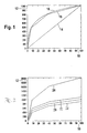
- FIG. 1 shows a diagram with three characteristics of the exposure sensitivity 14, 16, 18 of a pixel of an image sensor.
- the exposure 10 is applied.
- the exposure 10 is hereby applied in freely defined virtual units from 0 to 100, the exposure 10 being, for example, a measure of the irradiance or the illuminance.
- the irradiance is a physical quantity that indicates the radiation power per area
- the illuminance is the corresponding photometric quantity with the unit Lux, which takes into account the spectral sensitivity of the human eye.
- the output signal 12 of the pixel of the image sensor is plotted as a freely defined virtual unit from 0 to 1000.
- the output signal 12 can be present as a digital or analog signal.
- FIG. 1 a linear characteristic of the exposure sensitivity 14 is shown.
- the diagram shows in FIG. 1 a logarithmic characteristic of the exposure sensitivity 16 and a sectional linear characteristic of the exposure sensitivity 18.
- FIG. 2 shows a diagram with four sections linear characteristics of the exposure sensitivity 20, 22, 24, 26 of a pixel of an image sensor depending on the gain and / or the offset.
- the exposure 10 is plotted in freely defined virtual units from 0 to 100.
- the output signal 12 of the pixel of the image sensor is plotted as a freely defined virtual unit from 0 to 2000.
- the gain (gain) is 1 and the offset 0.
- the offset in the second characteristic of the exposure sensitivity 22 has a value of +100
- the third characteristic of the exposure sensitivity 24 it has a value of -100 having.
- the gain is 1.
- the gain is 2 at an offset of 0. Changing the offset shifts the exposure sensitivity characteristic in the ordinate direction , while a change in the gain and / or a change in the integration time spreads or upsets the characteristic curve of the exposure sensitivity in the ordinate direction.
- a freely configurable, section-wise linear characteristic of the exposure sensitivity such as the first characteristic of the exposure sensitivity 20 in FIG. 2 , leads to more degrees of freedom in the adjustment of at least one pixel of the image sensor, since here individual sections can be set individually.
- it is hereby alternatively or additionally possible to change the shape of the characteristic curve of the exposure sensitivity 20, 22, 24, 26.
- FIG. 3 Fig. 12 shows a block diagram of the preferred embodiment consisting of an image sensor 40 and a processing unit 42 with different modules 50, 52, 54, 56.
- the image sensor 40 is located behind the windshield of a motor vehicle in the region of the interior rearview mirror.
- the image sensor 40 is installed in the bumper and / or in a side mirror and / or in the tail light.
- the image sensor 40 is oriented such that the image capture area comprises at least a portion of the surroundings of the motor vehicle.
- the image sensor 40 used in the preferred embodiment is a black and white CMOS image sensor with a resolution of 640 ⁇ 480 pixels with 8-bit gray scale resolution.
- the image sensor 40 has a freely configurable, section-wise linear characteristic of the exposure sensitivity, it being possible to set the number of sections and / or the position of the sections and / or the size of the individual sections and / or at least one parameter of the linear functions in a section. Alternatively or additionally, the gain and / or the offset and / or the integration time is set. In the preferred embodiment, the adjustment of the exposure sensitivity characteristic for all pixels of the image sensor 40 is set in common.
- the individual modules 50, 52, 54, 56 of the processing unit 42 are implemented in the preferred embodiment in a digital microprocessor, which implements the functions described below of the modules 50, 52, 54, 56 as programs, program parts or program steps.
- the individual modules 50, 52, 54, 56 are distributed.
- the image signals generated by the image sensor 40 are transmitted to the processing unit 42 via the signal line 44.
- the transmission of the image signals is carried out electrically and / or optically and / or by radio.
- the module for Determination of the histogram 50 determines the histogram of the gray values.
- the histogram of the gray values indicates the frequency of the individual gray values of a picture or a picture detail. In the preferred embodiment, the histogram of gray levels is determined from an overall image.
- the module for determining the histogram 50 in dependence on the set parameters, such as the gain and / or the offset and / or the integration time, and / or the parameters for adjusting the characteristic of the exposure sensitivity, such as the number of sections of the characteristic the exposure sensitivity and / or the position of the sections of the exposure sensitivity characteristic and / or the size of the sections of the exposure sensitivity characteristic and / or the at least one linear function parameter which determines the associated illuminance in freely definable virtual units.
- the optimum characteristic curve is calculated as a function of the histogram of the gray values determined in the preceding module for determining the histogram 50.
- the thus calculated mapping function of illuminances ⁇ to gray values g represents the information theoretic optimal characteristic of the exposure sensitivity for the given histogram and is an optimal characteristic of the exposure sensitivity.
- the optimum characteristic of the exposure sensitivity is basically characterized in that after the adjustment of the characteristic curve of the exposure sensitivity of the image sensor, which is approximated to the determined optimum characteristic of the exposure sensitivity, the frequency of the individual gray values in the histogram of the image signals, ie the camera image of the image sensor, approximates is constant and / or the gray value density of the histogram of the image signals, ie the camera image of the image sensor, is approximately constant.
- the frequency of a gray value indicates the number of pixels within the camera image that have this gray value, based on the total number of pixels.
- a constant frequency of gray values within a histogram of an image is referred to as a uniformly distributed histogram.
- the gray value density denotes the sum of the frequencies h (g i ) of gray values g i in an interval ⁇ g of gray values with respect to this interval ⁇ g: ( ⁇ h (g i )) / ⁇ g.
- the section-wise linear characteristic curve of the exposure sensitivity of the pixels of the image sensor is now selected such that it coincides as exactly as possible with the optimum characteristic curve obtained.
- this is done by numerically minimizing the square distance between the optimum exposure sensitivity characteristic and the sectional linear characteristic while varying the parameters.
- the Hwa-Cho Yi sensor data evaluation with fuzzy logic for automated deburring ( Kunststoff: Hanser-Verlag, 1993, dissertation TU Berlin, pages 76-79 ) described segmentation method.
- This segmentation method uses the iterative endpoint method or the principle of finding the longest segment.
- the determined parameters such as the gain and / or the offset and / or the integration time and / or the number of the exposure sensitivity characteristic sections and / or the position of the exposure sensitivity characteristic sections and / or the photosensitive exposure curve sections; / or at least one parameter of the linear functions are transmitted from the module for approximation of the characteristic of the exposure sensitivity 54 to the module for generating the adjustment signals 56.
- the at least one corresponding adjustment signal is determined from the determined parameters and the at least one adjustment signal is transmitted via the signal line 46 electrically and / or optically and / or by radio to the image sensor 40.
- the adjustment of the exposure sensitivity characteristic takes place as a function of at least one adjustment signal.
- the exposure sensitivity characteristic becomes effective in the image following the determination of the optimum exposure sensitivity characteristic.
- the characteristic curve of the exposure sensitivity in the same image and / or in the next but one image and / or in at least one other image is effective.
- the use of the inventive method and / or the processing unit according to the invention and / or the computer program according to the invention for adjusting the characteristic of the exposure sensitivity of at least one pixel of at least one image sensor becomes clear when the at least one image sensor receives an input image with a gray value wedge, the gray value wedge comprising two sections with different slope of the Gray values exists.
- the gray value wedge comprising two sections with different slope of the Gray values exists.
- differently adjusted and / or controlled and / or controlled image sensors with sections linear characteristic occurs at a variable overall illumination of the gray value wedge caused by the kinked characteristic of the exposure sensitivity sham contour, which does not match the section boundary of the gray value wedge.
- this dummy contour will lie exactly on or at least very close to the dividing line, even if the overall illumination is changed.
- the described method and / or the processing unit and / or the computer program are not limited to the adjustment of the characteristic curve of the exposure sensitivity of an image sensor in a motor vehicle.
- the described procedure with the corresponding features can also be applied outside of motor vehicle technology, and moreover with more than one image sensor.
- the described method and / or the processing unit and / or the computer program is not limited to the adjustment of the exposure sensitivity characteristic. Rather, the procedure is particularly suitable for controlling and / or regulating the characteristic of the exposure sensitivity.
- the characteristic of the exposure sensitivity of at least one pixel of at least one image sensor is adjusted as a function of at least one image section of at least one image sensor.
- the image detail can be manually specified by at least one user, while in a further embodiment the image detail is determined automatically by the processing unit.
- the adjustment of the characteristic curve of the exposure sensitivity of at least one pixel of at least one image sensor in dependence on image signals of at least one stereo camera is performed.
- the stereo camera consists of at least two image sensors, which record essentially the same scene. For example, in this case a common histogram of the gray values is calculated from the images and / or image sections and used to determine the optimum characteristic of the exposure sensitivity.
- the described approach is not limited to black and white CMOS image sensor with a resolution of 640x480 pixels with 8-bit gray scale resolution.
- the method and / or the processing unit and / or the computer program is suitable for all types of image sensors.
- the image sensors have a configurable characteristic curve of the exposure sensitivity with sections with functions, in particular continuous and / or linear functions.
- a CCD image sensor is used.
- an image sensor with a section-wise logarithmic characteristic curve is alternatively or additionally used.
- the described procedure with the corresponding features is furthermore applicable to at least one color image sensor.
- the characteristic curve of the exposure sensitivity of at least one pixel of at least one image sensor is set in a further variant.
Claims (7)
- Procédé de réglage de la courbe caractéristique de sensibilité lumineuse d'au moins un pixel d'au moins un capteur d'image (40), notamment dans un véhicule automobile selon lequel
on règle la courbe caractéristique de la sensibilité d'éclairage (20, 22, 24, 26) en fonction des signaux d'image de la scène captée par au moins un capteur d'image (40) de façon que la fréquence des niveaux de gris de l'histogramme des signaux d'image d'au moins un capteur d'image (40) de la scène saisie soit constante,
dans le capteur d'image, on règle la courbe caractéristique de la sensibilité d'éclairage (20, 22, 24, 26) formée de segments de fonctions linéaires, selon un signal de réglage (40), généré, le capteur d'image (40) ayant une courbe linéaire par segments, configurée librement pour la sensibilité d'éclairage (20, 22, 24, 26), et le nombre de segments est réglable. - Procédé selon la revendication 1,
caractérisé en ce qu'
on règle le gain et/ou le décalage et/ou le temps d'intégration et/ou au moins un autre paramètre pour régler la courbe caractéristique de la sensibilité d'éclairage d'au moins un pixel d'au moins un capteur d'image, selon lequel cet autre paramètre de réglage de la courbe caractéristique de la sensibilité lumineuse est au moins un paramètre de réglage du nombre de segments de la courbe caractéristique de la sensibilité d'éclairage et/ou au moins un paramètre de réglage de la position des segments de la courbe caractéristique de la sensibilité d'éclairage et/ou au moins un paramètre de réglage de la position des segments de la position de la courbe caractéristique de la sensibilité d'éclairage et/ou au moins un paramètre de réglage de la position des segments de la courbe caractéristique de la sensibilité d'éclairage et/ou au moins un paramètre de réglage de la dimension des segments de la courbe caractéristique de la sensibilité d'éclairage et/ou au moins un paramètre de réglage d'au moins une fonction. - Procédé selon l'une des revendications précédentes,
caractérisé en ce que
la courbe caractéristique de la sensibilité d'éclairage d'au moins un pixel d'au moins un capteur d'image est réglée en fonction des signaux d'image d'au moins deux capteurs d'image, notamment d'au moins une caméra stéréoscopique. - Dispositif comportant au moins un capteur d'image (40) et une unité de traitement (42) pour générer au moins un signal de réglage de la courbe caractéristique de la sensibilité d'éclairage (20, 22, 24, 26) d'au moins un pixel d'au moins un capteur d'image (40), notamment dans un véhicule automobile, selon lequel un module (56) de l'unité de traitement (42) génère au moins un signal de réglage pour régler dans le capteur d'image (40) la courbe caractéristique de la sensibilité d'éclairage (20, 22, 24, 26) formée de segments de fonctions linéaires, selon des signaux d'image de la scène saisie par au moins un capteur d'image (40) de façon que la fréquence des niveaux de gris de l'histogramme des signaux d'image de la scène saisie par au moins un capteur d'image (60) soit constante, le capteur d'image (40) ayant une caractéristique linéaire par segments à configuration libre de la sensibilité d'éclairage (20, 22, 24, 26), le nombre de segments étant réglable.
- Dispositif selon la revendication 4,
caractérisé en ce que
le module de l'unité de traitement génère au moins un signal de réglage pour régler le gain et/ ou le décalage et/ou le temps d'intégration et/ ou au moins un autre signal de réglage pour régler la courbe caractéristique de la sensibilité d'éclairage d'au moins un pixel d'au moins un capteur d'image,
au moins un autre signal de réglage servant à régler la courbe caractéristique de la sensibilité d'éclairage étant au moins un signal de réglage du nombre de segments de la courbe caractéristique de la sensibilité d'éclairage et/ou au moins un signal de réglage de la position des segments de la courbe caractéristique de la sensibilité d'éclairage et/ou au moins un signal de réglage de la grandeur du segment de la sensibilité d'éclairage de la courbe caractéristique et/ou au moins un signal de réglage d'au moins une fonction. - Dispositif selon l'une des revendications 4 ou 5,
caractérisé en ce que
le module de l'unité de traitement génère au moins un signal de réglage pour régler la courbe caractéristique de la sensibilité d'éclairage d'au moins un pixel d'au moins un capteur d'image en fonction des signaux d'image d'au moins deux capteurs d'image, notamment d'au moins une caméra stéréoscopique. - Programme d'ordinateur comportant des moyens de codes de programmes pour exécuter toutes les étapes de l'une quelconque des revendications 1 à 3, lorsque le programme est exécuté sur un ordinateur.
Applications Claiming Priority (3)
| Application Number | Priority Date | Filing Date | Title |
|---|---|---|---|
| DE10301898 | 2003-01-17 | ||
| DE10301898A DE10301898A1 (de) | 2003-01-17 | 2003-01-17 | Verfahren zur Einstellung eines Bildsensors |
| PCT/DE2003/003744 WO2004068850A1 (fr) | 2003-01-17 | 2003-11-12 | Procede de reglage d'un capteur d'images |
Publications (2)
| Publication Number | Publication Date |
|---|---|
| EP1588554A1 EP1588554A1 (fr) | 2005-10-26 |
| EP1588554B1 true EP1588554B1 (fr) | 2008-02-20 |
Family
ID=32667662
Family Applications (1)
| Application Number | Title | Priority Date | Filing Date |
|---|---|---|---|
| EP03779688A Expired - Lifetime EP1588554B1 (fr) | 2003-01-17 | 2003-11-12 | Procede de reglage d'un capteur d'images |
Country Status (5)
| Country | Link |
|---|---|
| US (1) | US20060228024A1 (fr) |
| EP (1) | EP1588554B1 (fr) |
| AT (1) | ATE387061T1 (fr) |
| DE (2) | DE10301898A1 (fr) |
| WO (1) | WO2004068850A1 (fr) |
Families Citing this family (10)
| Publication number | Priority date | Publication date | Assignee | Title |
|---|---|---|---|---|
| FR2884051B1 (fr) * | 2005-04-01 | 2007-06-01 | Atmel Grenoble Soc Par Actions | Capteur d'image cmos a grande dynamique |
| DE102006027121A1 (de) * | 2006-06-12 | 2007-12-13 | Robert Bosch Gmbh | Bildaufnahmesystem und Verfahren für die Entfernungsbestimmung mit einem Bildaufnahmesystem |
| DE102006061658A1 (de) * | 2006-12-27 | 2008-07-03 | Siemens Ag | Belichtungsregelung für HDR-Kamera |
| DE102008003800A1 (de) | 2008-01-10 | 2009-07-16 | Robert Bosch Gmbh | Verfahren und Vorrichtung zur Bilderfassung für Kraftfahrzeuge |
| DE102008000819B4 (de) * | 2008-03-26 | 2018-12-27 | Robert Bosch Gmbh | Steuereinrichtung zur Steuerung eines Bildsensors, Bildaufnahmesystem und Verfahren zur Regelung eines Bildsensors eines Fahrzeugs |
| DE102009055269B4 (de) | 2009-12-23 | 2012-12-06 | Robert Bosch Gmbh | Verfahren zur Bestimmung der Relativbewegung mittels einer HDR-Kamera |
| US9058510B1 (en) * | 2011-07-29 | 2015-06-16 | Rockwell Collins, Inc. | System for and method of controlling display characteristics including brightness and contrast |
| CN107067390B (zh) * | 2017-03-09 | 2020-01-14 | 深圳怡化电脑股份有限公司 | 一种检测图像传感器的灰度分辨率的方法及装置 |
| DE102017219276A1 (de) * | 2017-10-26 | 2019-05-02 | Continental Automotive Gmbh | Belichtungssteuerung für eine Kamera mit nichtlinearer Kennlinie |
| CN108965700B (zh) * | 2018-07-05 | 2021-09-03 | 平安科技(深圳)有限公司 | 一种拍摄控制方法、终端及计算机可读介质 |
Family Cites Families (23)
| Publication number | Priority date | Publication date | Assignee | Title |
|---|---|---|---|---|
| IL87306A0 (en) * | 1988-08-02 | 1989-01-31 | Technion Res & Dev Foundation | Wide dynamic range camera |
| EP0548079A1 (fr) * | 1990-05-25 | 1993-06-30 | Axiom Innovation Limited | Systeme d'acquisition d'images |
| EP0631683B1 (fr) * | 1992-03-20 | 2001-08-01 | Commonwealth Scientific And Industrial Research Organisation | Systeme de surveillance d'un objet |
| US6204881B1 (en) * | 1993-10-10 | 2001-03-20 | Canon Kabushiki Kaisha | Image data processing apparatus which can combine a plurality of images at different exposures into an image with a wider dynamic range |
| DE69534929T2 (de) * | 1994-09-30 | 2006-11-16 | Matsushita Electric Industrial Co., Ltd., Kadoma | Bildaufnahmevorrichtung |
| US6040858A (en) * | 1994-11-18 | 2000-03-21 | Canon Kabushiki Kaisha | Method and apparatus for expanding the dynamic range of sensed color images |
| US5812286A (en) * | 1995-08-30 | 1998-09-22 | Hewlett-Packard Company | Automatic color processing to correct hue shift and incorrect exposure |
| US5828793A (en) * | 1996-05-06 | 1998-10-27 | Massachusetts Institute Of Technology | Method and apparatus for producing digital images having extended dynamic ranges |
| US6061091A (en) * | 1996-05-30 | 2000-05-09 | Agfa Gevaert N.V. | Detection of and correction for specular reflections in digital image acquisition |
| JP3280888B2 (ja) * | 1996-08-19 | 2002-05-13 | 三星電子株式会社 | 量子化された平均−マッチングヒストグラム等化を用いた画質改善方法及びその回路 |
| DE19701484A1 (de) * | 1997-01-17 | 1998-07-23 | Bosch Gmbh Robert | Verfahren zur Regelung der Belichtung von Videokameras |
| KR100261214B1 (ko) * | 1997-02-27 | 2000-07-01 | 윤종용 | 영상처리 시스템의 콘트라스트 확장장치에서 히스토그램 등화방법 및 장치 |
| JP3141940B2 (ja) * | 1998-05-08 | 2001-03-07 | 日本電気株式会社 | カラーリニアイメージセンサ |
| KR100322596B1 (ko) * | 1998-12-15 | 2002-07-18 | 윤종용 | 입력 영상의 밝기를 유지하는 화질 개선 장치 및 그 방법 |
| US6687400B1 (en) * | 1999-06-16 | 2004-02-03 | Microsoft Corporation | System and process for improving the uniformity of the exposure and tone of a digital image |
| JP3758452B2 (ja) * | 2000-02-28 | 2006-03-22 | コニカミノルタビジネステクノロジーズ株式会社 | 記録媒体、並びに、画像処理装置および画像処理方法 |
| US6348681B1 (en) * | 2000-06-05 | 2002-02-19 | National Semiconductor Corporation | Method and circuit for setting breakpoints for active pixel sensor cell to achieve piecewise linear transfer function |
| CN1184796C (zh) * | 2001-07-26 | 2005-01-12 | 佳能株式会社 | 图象处理方法和设备以及图象处理系统 |
| US7433532B2 (en) * | 2002-05-01 | 2008-10-07 | Kestrel Corporation | Max entropy optimized retinal camera |
| JP2004096505A (ja) * | 2002-08-30 | 2004-03-25 | Konica Minolta Holdings Inc | 画像処理方法、画像処理装置、画像記録装置、プログラム及び記録媒体。 |
| US7359572B2 (en) * | 2003-03-26 | 2008-04-15 | Microsoft Corporation | Automatic analysis and adjustment of digital images with exposure problems |
| US7142723B2 (en) * | 2003-07-18 | 2006-11-28 | Microsoft Corporation | System and process for generating high dynamic range images from multiple exposures of a moving scene |
| US7110046B2 (en) * | 2003-11-04 | 2006-09-19 | Cyberlink Corp. | Method for dynamically adjusting video brightness |
-
2003
- 2003-01-17 DE DE10301898A patent/DE10301898A1/de not_active Ceased
- 2003-11-12 DE DE50309226T patent/DE50309226D1/de not_active Expired - Lifetime
- 2003-11-12 US US10/542,672 patent/US20060228024A1/en not_active Abandoned
- 2003-11-12 EP EP03779688A patent/EP1588554B1/fr not_active Expired - Lifetime
- 2003-11-12 WO PCT/DE2003/003744 patent/WO2004068850A1/fr active IP Right Grant
- 2003-11-12 AT AT03779688T patent/ATE387061T1/de not_active IP Right Cessation
Also Published As
| Publication number | Publication date |
|---|---|
| US20060228024A1 (en) | 2006-10-12 |
| EP1588554A1 (fr) | 2005-10-26 |
| DE50309226D1 (fr) | 2008-04-03 |
| ATE387061T1 (de) | 2008-03-15 |
| WO2004068850A1 (fr) | 2004-08-12 |
| DE10301898A1 (de) | 2004-08-05 |
Similar Documents
| Publication | Publication Date | Title |
|---|---|---|
| DE10304703B4 (de) | Verfahren und Vorrichtung zur Sichtbarmachung der Umgebung eines Fahrzeugs mit umgebungsabhängiger Fusion eines Infrarot- und eines Visuell-Abbilds | |
| DE4447788B4 (de) | Verfahren zum Steuern der Verschlußgeschwindigkeit einer stereoskopischen Abbildungsvorrichtung, insbesondere bei einem System zur Abstandserkennung | |
| DE69937342T2 (de) | Bilderfassungs-System und Verfahren mit dynamischer Helligkeitssteuerung | |
| DE102008063122B4 (de) | Belichtungssteuervorrichtung und Belichtungssteuerprogramm für elektronische Fahrzeugkamera | |
| DE102009036844B4 (de) | Belichtungsbestimmungsvorrichtung und Bildverarbeitungsvorrichtung | |
| DE112006000457T5 (de) | Infrarot-Kamerasystem und -Verfahren | |
| EP1588554B1 (fr) | Procede de reglage d'un capteur d'images | |
| DE112014002331T5 (de) | Bildverarbeitungsvorrichtung und Bildverarbeitungsverfahren | |
| DE102017219694A1 (de) | Bilderzeugungsvorrichtung | |
| DE102016121755A1 (de) | Verfahren zum Bestimmen eines zusammengesetzten Bilds eines Umgebungsbereichs eines Kraftfahrzeugs mit Anpassung von Helligkeit und/oder Farbe, Kamerasystem sowie Krafzfahrzeug | |
| WO2021121491A2 (fr) | Conversion de données image d'entrée d'une pluralité de caméras de véhicule d'un système à visibilité périphérique en données image de sortie optimisées | |
| DE102019220168A1 (de) | Helligkeits-Umwandlung von Bildern einer Kamera | |
| EP2095628B1 (fr) | Régulation de l'éclairage pour une caméra hdr | |
| DE10146786A1 (de) | Einrichtung zur automatischen Schaltung von Beleuchtungseinrichtungen eines Fahrzeugs | |
| WO2009086970A1 (fr) | Procédé et dispositif de saisie d'images pour véhicules à moteur | |
| EP1447985A1 (fr) | Appareil et méthode pour améliorer la vision dans un vehicule | |
| DE10318499B4 (de) | Verfahren und Vorrichtung zur Einstellung eines Bildsensors | |
| EP1476326A1 (fr) | Systeme pour regler automatiquement la luminosite du faisceau lumineux emis par un dispositif d'eclairage arriere d'un vehicule | |
| DE2908483C2 (fr) | ||
| DE102004047476B4 (de) | Vorrichtung und Verfahren zur Einstellung einer Kamera | |
| DE102020201487A1 (de) | Vorrichtung und verfahren zur erzeugung von informationen über die beleuchtungsstärke an einem fahrzeug | |
| DE102020106967A1 (de) | Festlegen eines aktuellen Fokusbereichs eines Kamerabildes basierend auf der Position der Fahrzeugkamera an dem Fahrzeug und einem aktuellen Bewegungsparameter | |
| DE102019106262A1 (de) | Abbildungsvorrichtung | |
| DE102017219253A1 (de) | Bilderzeugungsvorrichtung | |
| EP3756157B1 (fr) | Procede de creation d'images panoramiques, programme d'ordinateur, appareil de control et vehicule associes |
Legal Events
| Date | Code | Title | Description |
|---|---|---|---|
| PUAI | Public reference made under article 153(3) epc to a published international application that has entered the european phase |
Free format text: ORIGINAL CODE: 0009012 |
|
| 17P | Request for examination filed |
Effective date: 20050817 |
|
| AK | Designated contracting states |
Kind code of ref document: A1 Designated state(s): AT BE BG CH CY CZ DE DK EE ES FI FR GB GR HU IE IT LI LU MC NL PT RO SE SI SK TR |
|
| GRAP | Despatch of communication of intention to grant a patent |
Free format text: ORIGINAL CODE: EPIDOSNIGR1 |
|
| GRAS | Grant fee paid |
Free format text: ORIGINAL CODE: EPIDOSNIGR3 |
|
| GRAA | (expected) grant |
Free format text: ORIGINAL CODE: 0009210 |
|
| AK | Designated contracting states |
Kind code of ref document: B1 Designated state(s): AT BE BG CH CY CZ DE DK EE ES FI FR GB GR HU IE IT LI LU MC NL PT RO SE SI SK TR |
|
| REG | Reference to a national code |
Ref country code: GB Ref legal event code: FG4D Free format text: NOT ENGLISH |
|
| REG | Reference to a national code |
Ref country code: CH Ref legal event code: EP |
|
| REG | Reference to a national code |
Ref country code: IE Ref legal event code: FG4D Free format text: LANGUAGE OF EP DOCUMENT: GERMAN |
|
| REF | Corresponds to: |
Ref document number: 50309226 Country of ref document: DE Date of ref document: 20080403 Kind code of ref document: P |
|
| PG25 | Lapsed in a contracting state [announced via postgrant information from national office to epo] |
Ref country code: ES Free format text: LAPSE BECAUSE OF FAILURE TO SUBMIT A TRANSLATION OF THE DESCRIPTION OR TO PAY THE FEE WITHIN THE PRESCRIBED TIME-LIMIT Effective date: 20080531 Ref country code: FI Free format text: LAPSE BECAUSE OF FAILURE TO SUBMIT A TRANSLATION OF THE DESCRIPTION OR TO PAY THE FEE WITHIN THE PRESCRIBED TIME-LIMIT Effective date: 20080220 |
|
| NLV1 | Nl: lapsed or annulled due to failure to fulfill the requirements of art. 29p and 29m of the patents act | ||
| PG25 | Lapsed in a contracting state [announced via postgrant information from national office to epo] |
Ref country code: SI Free format text: LAPSE BECAUSE OF FAILURE TO SUBMIT A TRANSLATION OF THE DESCRIPTION OR TO PAY THE FEE WITHIN THE PRESCRIBED TIME-LIMIT Effective date: 20080220 |
|
| REG | Reference to a national code |
Ref country code: IE Ref legal event code: FD4D |
|
| ET | Fr: translation filed | ||
| PG25 | Lapsed in a contracting state [announced via postgrant information from national office to epo] |
Ref country code: NL Free format text: LAPSE BECAUSE OF FAILURE TO SUBMIT A TRANSLATION OF THE DESCRIPTION OR TO PAY THE FEE WITHIN THE PRESCRIBED TIME-LIMIT Effective date: 20080220 Ref country code: IE Free format text: LAPSE BECAUSE OF FAILURE TO SUBMIT A TRANSLATION OF THE DESCRIPTION OR TO PAY THE FEE WITHIN THE PRESCRIBED TIME-LIMIT Effective date: 20080220 Ref country code: DK Free format text: LAPSE BECAUSE OF FAILURE TO SUBMIT A TRANSLATION OF THE DESCRIPTION OR TO PAY THE FEE WITHIN THE PRESCRIBED TIME-LIMIT Effective date: 20080220 Ref country code: CZ Free format text: LAPSE BECAUSE OF FAILURE TO SUBMIT A TRANSLATION OF THE DESCRIPTION OR TO PAY THE FEE WITHIN THE PRESCRIBED TIME-LIMIT Effective date: 20080220 Ref country code: SK Free format text: LAPSE BECAUSE OF FAILURE TO SUBMIT A TRANSLATION OF THE DESCRIPTION OR TO PAY THE FEE WITHIN THE PRESCRIBED TIME-LIMIT Effective date: 20080220 Ref country code: SE Free format text: LAPSE BECAUSE OF FAILURE TO SUBMIT A TRANSLATION OF THE DESCRIPTION OR TO PAY THE FEE WITHIN THE PRESCRIBED TIME-LIMIT Effective date: 20080520 Ref country code: PT Free format text: LAPSE BECAUSE OF FAILURE TO SUBMIT A TRANSLATION OF THE DESCRIPTION OR TO PAY THE FEE WITHIN THE PRESCRIBED TIME-LIMIT Effective date: 20080721 |
|
| PG25 | Lapsed in a contracting state [announced via postgrant information from national office to epo] |
Ref country code: RO Free format text: LAPSE BECAUSE OF FAILURE TO SUBMIT A TRANSLATION OF THE DESCRIPTION OR TO PAY THE FEE WITHIN THE PRESCRIBED TIME-LIMIT Effective date: 20080220 |
|
| PLBE | No opposition filed within time limit |
Free format text: ORIGINAL CODE: 0009261 |
|
| STAA | Information on the status of an ep patent application or granted ep patent |
Free format text: STATUS: NO OPPOSITION FILED WITHIN TIME LIMIT |
|
| 26N | No opposition filed |
Effective date: 20081121 |
|
| PG25 | Lapsed in a contracting state [announced via postgrant information from national office to epo] |
Ref country code: BG Free format text: LAPSE BECAUSE OF FAILURE TO SUBMIT A TRANSLATION OF THE DESCRIPTION OR TO PAY THE FEE WITHIN THE PRESCRIBED TIME-LIMIT Effective date: 20080520 Ref country code: EE Free format text: LAPSE BECAUSE OF FAILURE TO SUBMIT A TRANSLATION OF THE DESCRIPTION OR TO PAY THE FEE WITHIN THE PRESCRIBED TIME-LIMIT Effective date: 20080220 |
|
| BERE | Be: lapsed |
Owner name: ROBERT BOSCH G.M.B.H. Effective date: 20081130 |
|
| PG25 | Lapsed in a contracting state [announced via postgrant information from national office to epo] |
Ref country code: MC Free format text: LAPSE BECAUSE OF NON-PAYMENT OF DUE FEES Effective date: 20081130 |
|
| REG | Reference to a national code |
Ref country code: CH Ref legal event code: PL |
|
| PG25 | Lapsed in a contracting state [announced via postgrant information from national office to epo] |
Ref country code: CY Free format text: LAPSE BECAUSE OF FAILURE TO SUBMIT A TRANSLATION OF THE DESCRIPTION OR TO PAY THE FEE WITHIN THE PRESCRIBED TIME-LIMIT Effective date: 20080220 |
|
| PG25 | Lapsed in a contracting state [announced via postgrant information from national office to epo] |
Ref country code: BE Free format text: LAPSE BECAUSE OF NON-PAYMENT OF DUE FEES Effective date: 20081130 |
|
| PG25 | Lapsed in a contracting state [announced via postgrant information from national office to epo] |
Ref country code: LI Free format text: LAPSE BECAUSE OF NON-PAYMENT OF DUE FEES Effective date: 20081130 Ref country code: CH Free format text: LAPSE BECAUSE OF NON-PAYMENT OF DUE FEES Effective date: 20081130 |
|
| PG25 | Lapsed in a contracting state [announced via postgrant information from national office to epo] |
Ref country code: AT Free format text: LAPSE BECAUSE OF NON-PAYMENT OF DUE FEES Effective date: 20081112 |
|
| PG25 | Lapsed in a contracting state [announced via postgrant information from national office to epo] |
Ref country code: LU Free format text: LAPSE BECAUSE OF NON-PAYMENT OF DUE FEES Effective date: 20081112 Ref country code: HU Free format text: LAPSE BECAUSE OF FAILURE TO SUBMIT A TRANSLATION OF THE DESCRIPTION OR TO PAY THE FEE WITHIN THE PRESCRIBED TIME-LIMIT Effective date: 20080821 |
|
| PG25 | Lapsed in a contracting state [announced via postgrant information from national office to epo] |
Ref country code: TR Free format text: LAPSE BECAUSE OF FAILURE TO SUBMIT A TRANSLATION OF THE DESCRIPTION OR TO PAY THE FEE WITHIN THE PRESCRIBED TIME-LIMIT Effective date: 20080220 |
|
| PG25 | Lapsed in a contracting state [announced via postgrant information from national office to epo] |
Ref country code: GR Free format text: LAPSE BECAUSE OF FAILURE TO SUBMIT A TRANSLATION OF THE DESCRIPTION OR TO PAY THE FEE WITHIN THE PRESCRIBED TIME-LIMIT Effective date: 20080521 |
|
| PGFP | Annual fee paid to national office [announced via postgrant information from national office to epo] |
Ref country code: IT Payment date: 20131125 Year of fee payment: 11 |
|
| REG | Reference to a national code |
Ref country code: FR Ref legal event code: PLFP Year of fee payment: 13 |
|
| PG25 | Lapsed in a contracting state [announced via postgrant information from national office to epo] |
Ref country code: IT Free format text: LAPSE BECAUSE OF NON-PAYMENT OF DUE FEES Effective date: 20141112 |
|
| REG | Reference to a national code |
Ref country code: FR Ref legal event code: PLFP Year of fee payment: 14 |
|
| REG | Reference to a national code |
Ref country code: FR Ref legal event code: PLFP Year of fee payment: 15 |
|
| PGFP | Annual fee paid to national office [announced via postgrant information from national office to epo] |
Ref country code: FR Payment date: 20191121 Year of fee payment: 17 |
|
| PGFP | Annual fee paid to national office [announced via postgrant information from national office to epo] |
Ref country code: DE Payment date: 20200124 Year of fee payment: 17 Ref country code: GB Payment date: 20191126 Year of fee payment: 17 |
|
| REG | Reference to a national code |
Ref country code: DE Ref legal event code: R119 Ref document number: 50309226 Country of ref document: DE |
|
| GBPC | Gb: european patent ceased through non-payment of renewal fee |
Effective date: 20201112 |
|
| PG25 | Lapsed in a contracting state [announced via postgrant information from national office to epo] |
Ref country code: FR Free format text: LAPSE BECAUSE OF NON-PAYMENT OF DUE FEES Effective date: 20201130 |
|
| PG25 | Lapsed in a contracting state [announced via postgrant information from national office to epo] |
Ref country code: DE Free format text: LAPSE BECAUSE OF NON-PAYMENT OF DUE FEES Effective date: 20210601 Ref country code: GB Free format text: LAPSE BECAUSE OF NON-PAYMENT OF DUE FEES Effective date: 20201112 |