EP1588554B1 - Method for adjusting an image sensor - Google Patents
Method for adjusting an image sensor Download PDFInfo
- Publication number
- EP1588554B1 EP1588554B1 EP03779688A EP03779688A EP1588554B1 EP 1588554 B1 EP1588554 B1 EP 1588554B1 EP 03779688 A EP03779688 A EP 03779688A EP 03779688 A EP03779688 A EP 03779688A EP 1588554 B1 EP1588554 B1 EP 1588554B1
- Authority
- EP
- European Patent Office
- Prior art keywords
- characteristic
- exposure sensitivity
- image sensor
- adjusting
- image
- Prior art date
- Legal status (The legal status is an assumption and is not a legal conclusion. Google has not performed a legal analysis and makes no representation as to the accuracy of the status listed.)
- Expired - Lifetime
Links
- 238000000034 method Methods 0.000 title claims abstract description 38
- 230000035945 sensitivity Effects 0.000 claims abstract description 88
- 238000012545 processing Methods 0.000 claims abstract description 21
- 238000004590 computer program Methods 0.000 claims description 10
- 238000012886 linear function Methods 0.000 claims description 9
- 230000010354 integration Effects 0.000 claims description 7
- 238000010586 diagram Methods 0.000 description 7
- 230000008901 benefit Effects 0.000 description 6
- 230000011218 segmentation Effects 0.000 description 5
- 230000008859 change Effects 0.000 description 3
- 238000005286 illumination Methods 0.000 description 3
- 230000008569 process Effects 0.000 description 2
- 238000012935 Averaging Methods 0.000 description 1
- 238000013459 approach Methods 0.000 description 1
- 230000005540 biological transmission Effects 0.000 description 1
- 230000001276 controlling effect Effects 0.000 description 1
- 238000011157 data evaluation Methods 0.000 description 1
- 230000001419 dependent effect Effects 0.000 description 1
- 238000011161 development Methods 0.000 description 1
- 230000018109 developmental process Effects 0.000 description 1
- 238000005516 engineering process Methods 0.000 description 1
- 238000013507 mapping Methods 0.000 description 1
- 230000005855 radiation Effects 0.000 description 1
- 230000001105 regulatory effect Effects 0.000 description 1
- 230000004044 response Effects 0.000 description 1
- 230000003595 spectral effect Effects 0.000 description 1
Images

Classifications
-
- G—PHYSICS
- G06—COMPUTING; CALCULATING OR COUNTING
- G06V—IMAGE OR VIDEO RECOGNITION OR UNDERSTANDING
- G06V20/00—Scenes; Scene-specific elements
- G06V20/50—Context or environment of the image
- G06V20/56—Context or environment of the image exterior to a vehicle by using sensors mounted on the vehicle
-
- G—PHYSICS
- G06—COMPUTING; CALCULATING OR COUNTING
- G06V—IMAGE OR VIDEO RECOGNITION OR UNDERSTANDING
- G06V10/00—Arrangements for image or video recognition or understanding
- G06V10/10—Image acquisition
- G06V10/12—Details of acquisition arrangements; Constructional details thereof
- G06V10/14—Optical characteristics of the device performing the acquisition or on the illumination arrangements
- G06V10/147—Details of sensors, e.g. sensor lenses
-
- H—ELECTRICITY
- H04—ELECTRIC COMMUNICATION TECHNIQUE
- H04N—PICTORIAL COMMUNICATION, e.g. TELEVISION
- H04N23/00—Cameras or camera modules comprising electronic image sensors; Control thereof
- H04N23/70—Circuitry for compensating brightness variation in the scene
Definitions
- the invention relates to a method and a processing unit for adjusting the characteristic curve of the exposure sensitivity of an image sensor, wherein the image sensor is located in particular in a motor vehicle.
- image sensors which detect the environment of the motor vehicle, it is desirable that the image sensors process this wide range of different irradiances.
- the image sensor is adapted to the viewing conditions by appropriate selection of the parameters gain, offset, integration time and / or aperture.
- the US 5,387,930 discloses an image enhancement electronic image capture system wherein feedback is provided to adjust the image brightness.
- the method described below for adjusting the characteristic curve of the exposure sensitivity of at least one pixel of at least one image sensor has the advantage that the generated image information has a high information content and a wide dynamic range.
- the method described below is particularly advantageous in the case of outdoor use of the at least one image sensor, since a large number of different irradiation intensities can occur simultaneously in a scene in the outdoor area.
- the method described below is suitable for use in a motor vehicle, since in this case, for example, road sections which lie simultaneously in full sun and have shadow areas can be imaged with a high information content of the image information.
- the method described below uses the additional degrees of freedom of a characteristic curve of the exposure sensitivity with sections of functions, in particular continuous and / or linear functions, so that the at least one image sensor captures a maximum of information about the currently imaged scene in its images.
- the approximation of the characteristic of the exposure sensitivity to the optimum characteristic of the exposure sensitivity by at least one numerical approximation method and / or at least one segmentation method has the advantage that the at least one segmentation method contributes to a simple implementation of the method on a microprocessor.
- Characteristics of the exposure sensitivity with section-wise linear functions contribute to the fact that the characteristic curves can be easily implemented in the image sensor and on the other hand they allow a simple algorithmic implementation of the method described below in the processing unit.
- a computer program with program code means is advantageous in order to carry out all steps or at least the essential steps of the described method when the program is executed on a computer.
- the use of a computer program enables the process to be adapted quickly and inexpensively, for example to different image sensors.
- the following describes a method and a processing unit for adjusting the characteristic of the exposure sensitivity of at least one pixel of at least one image sensor in a motor vehicle.
- depending on Image signals of at least one image sensor from the histogram of the gray values of at least one image determines the optimum characteristic of the exposure sensitivity.
- the freely definable, section-wise linear characteristic of the image sensor is chosen so that it at least approximately coincides with the optimum characteristic curve.
- the shape of the characteristic is set alternatively or additionally.
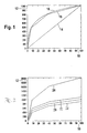
- FIG. 1 shows a diagram with three characteristics of the exposure sensitivity 14, 16, 18 of a pixel of an image sensor.
- the exposure 10 is applied.
- the exposure 10 is hereby applied in freely defined virtual units from 0 to 100, the exposure 10 being, for example, a measure of the irradiance or the illuminance.
- the irradiance is a physical quantity that indicates the radiation power per area
- the illuminance is the corresponding photometric quantity with the unit Lux, which takes into account the spectral sensitivity of the human eye.
- the output signal 12 of the pixel of the image sensor is plotted as a freely defined virtual unit from 0 to 1000.
- the output signal 12 can be present as a digital or analog signal.
- FIG. 1 a linear characteristic of the exposure sensitivity 14 is shown.
- the diagram shows in FIG. 1 a logarithmic characteristic of the exposure sensitivity 16 and a sectional linear characteristic of the exposure sensitivity 18.
- FIG. 2 shows a diagram with four sections linear characteristics of the exposure sensitivity 20, 22, 24, 26 of a pixel of an image sensor depending on the gain and / or the offset.
- the exposure 10 is plotted in freely defined virtual units from 0 to 100.
- the output signal 12 of the pixel of the image sensor is plotted as a freely defined virtual unit from 0 to 2000.
- the gain (gain) is 1 and the offset 0.
- the offset in the second characteristic of the exposure sensitivity 22 has a value of +100
- the third characteristic of the exposure sensitivity 24 it has a value of -100 having.
- the gain is 1.
- the gain is 2 at an offset of 0. Changing the offset shifts the exposure sensitivity characteristic in the ordinate direction , while a change in the gain and / or a change in the integration time spreads or upsets the characteristic curve of the exposure sensitivity in the ordinate direction.
- a freely configurable, section-wise linear characteristic of the exposure sensitivity such as the first characteristic of the exposure sensitivity 20 in FIG. 2 , leads to more degrees of freedom in the adjustment of at least one pixel of the image sensor, since here individual sections can be set individually.
- it is hereby alternatively or additionally possible to change the shape of the characteristic curve of the exposure sensitivity 20, 22, 24, 26.
- FIG. 3 Fig. 12 shows a block diagram of the preferred embodiment consisting of an image sensor 40 and a processing unit 42 with different modules 50, 52, 54, 56.
- the image sensor 40 is located behind the windshield of a motor vehicle in the region of the interior rearview mirror.
- the image sensor 40 is installed in the bumper and / or in a side mirror and / or in the tail light.
- the image sensor 40 is oriented such that the image capture area comprises at least a portion of the surroundings of the motor vehicle.
- the image sensor 40 used in the preferred embodiment is a black and white CMOS image sensor with a resolution of 640 ⁇ 480 pixels with 8-bit gray scale resolution.
- the image sensor 40 has a freely configurable, section-wise linear characteristic of the exposure sensitivity, it being possible to set the number of sections and / or the position of the sections and / or the size of the individual sections and / or at least one parameter of the linear functions in a section. Alternatively or additionally, the gain and / or the offset and / or the integration time is set. In the preferred embodiment, the adjustment of the exposure sensitivity characteristic for all pixels of the image sensor 40 is set in common.
- the individual modules 50, 52, 54, 56 of the processing unit 42 are implemented in the preferred embodiment in a digital microprocessor, which implements the functions described below of the modules 50, 52, 54, 56 as programs, program parts or program steps.
- the individual modules 50, 52, 54, 56 are distributed.
- the image signals generated by the image sensor 40 are transmitted to the processing unit 42 via the signal line 44.
- the transmission of the image signals is carried out electrically and / or optically and / or by radio.
- the module for Determination of the histogram 50 determines the histogram of the gray values.
- the histogram of the gray values indicates the frequency of the individual gray values of a picture or a picture detail. In the preferred embodiment, the histogram of gray levels is determined from an overall image.
- the module for determining the histogram 50 in dependence on the set parameters, such as the gain and / or the offset and / or the integration time, and / or the parameters for adjusting the characteristic of the exposure sensitivity, such as the number of sections of the characteristic the exposure sensitivity and / or the position of the sections of the exposure sensitivity characteristic and / or the size of the sections of the exposure sensitivity characteristic and / or the at least one linear function parameter which determines the associated illuminance in freely definable virtual units.
- the optimum characteristic curve is calculated as a function of the histogram of the gray values determined in the preceding module for determining the histogram 50.
- the thus calculated mapping function of illuminances ⁇ to gray values g represents the information theoretic optimal characteristic of the exposure sensitivity for the given histogram and is an optimal characteristic of the exposure sensitivity.
- the optimum characteristic of the exposure sensitivity is basically characterized in that after the adjustment of the characteristic curve of the exposure sensitivity of the image sensor, which is approximated to the determined optimum characteristic of the exposure sensitivity, the frequency of the individual gray values in the histogram of the image signals, ie the camera image of the image sensor, approximates is constant and / or the gray value density of the histogram of the image signals, ie the camera image of the image sensor, is approximately constant.
- the frequency of a gray value indicates the number of pixels within the camera image that have this gray value, based on the total number of pixels.
- a constant frequency of gray values within a histogram of an image is referred to as a uniformly distributed histogram.
- the gray value density denotes the sum of the frequencies h (g i ) of gray values g i in an interval ⁇ g of gray values with respect to this interval ⁇ g: ( ⁇ h (g i )) / ⁇ g.
- the section-wise linear characteristic curve of the exposure sensitivity of the pixels of the image sensor is now selected such that it coincides as exactly as possible with the optimum characteristic curve obtained.
- this is done by numerically minimizing the square distance between the optimum exposure sensitivity characteristic and the sectional linear characteristic while varying the parameters.
- the Hwa-Cho Yi sensor data evaluation with fuzzy logic for automated deburring ( Kunststoff: Hanser-Verlag, 1993, dissertation TU Berlin, pages 76-79 ) described segmentation method.
- This segmentation method uses the iterative endpoint method or the principle of finding the longest segment.
- the determined parameters such as the gain and / or the offset and / or the integration time and / or the number of the exposure sensitivity characteristic sections and / or the position of the exposure sensitivity characteristic sections and / or the photosensitive exposure curve sections; / or at least one parameter of the linear functions are transmitted from the module for approximation of the characteristic of the exposure sensitivity 54 to the module for generating the adjustment signals 56.
- the at least one corresponding adjustment signal is determined from the determined parameters and the at least one adjustment signal is transmitted via the signal line 46 electrically and / or optically and / or by radio to the image sensor 40.
- the adjustment of the exposure sensitivity characteristic takes place as a function of at least one adjustment signal.
- the exposure sensitivity characteristic becomes effective in the image following the determination of the optimum exposure sensitivity characteristic.
- the characteristic curve of the exposure sensitivity in the same image and / or in the next but one image and / or in at least one other image is effective.
- the use of the inventive method and / or the processing unit according to the invention and / or the computer program according to the invention for adjusting the characteristic of the exposure sensitivity of at least one pixel of at least one image sensor becomes clear when the at least one image sensor receives an input image with a gray value wedge, the gray value wedge comprising two sections with different slope of the Gray values exists.
- the gray value wedge comprising two sections with different slope of the Gray values exists.
- differently adjusted and / or controlled and / or controlled image sensors with sections linear characteristic occurs at a variable overall illumination of the gray value wedge caused by the kinked characteristic of the exposure sensitivity sham contour, which does not match the section boundary of the gray value wedge.
- this dummy contour will lie exactly on or at least very close to the dividing line, even if the overall illumination is changed.
- the described method and / or the processing unit and / or the computer program are not limited to the adjustment of the characteristic curve of the exposure sensitivity of an image sensor in a motor vehicle.
- the described procedure with the corresponding features can also be applied outside of motor vehicle technology, and moreover with more than one image sensor.
- the described method and / or the processing unit and / or the computer program is not limited to the adjustment of the exposure sensitivity characteristic. Rather, the procedure is particularly suitable for controlling and / or regulating the characteristic of the exposure sensitivity.
- the characteristic of the exposure sensitivity of at least one pixel of at least one image sensor is adjusted as a function of at least one image section of at least one image sensor.
- the image detail can be manually specified by at least one user, while in a further embodiment the image detail is determined automatically by the processing unit.
- the adjustment of the characteristic curve of the exposure sensitivity of at least one pixel of at least one image sensor in dependence on image signals of at least one stereo camera is performed.
- the stereo camera consists of at least two image sensors, which record essentially the same scene. For example, in this case a common histogram of the gray values is calculated from the images and / or image sections and used to determine the optimum characteristic of the exposure sensitivity.
- the described approach is not limited to black and white CMOS image sensor with a resolution of 640x480 pixels with 8-bit gray scale resolution.
- the method and / or the processing unit and / or the computer program is suitable for all types of image sensors.
- the image sensors have a configurable characteristic curve of the exposure sensitivity with sections with functions, in particular continuous and / or linear functions.
- a CCD image sensor is used.
- an image sensor with a section-wise logarithmic characteristic curve is alternatively or additionally used.
- the described procedure with the corresponding features is furthermore applicable to at least one color image sensor.
- the characteristic curve of the exposure sensitivity of at least one pixel of at least one image sensor is set in a further variant.
Landscapes
- Engineering & Computer Science (AREA)
- Multimedia (AREA)
- Theoretical Computer Science (AREA)
- Physics & Mathematics (AREA)
- General Physics & Mathematics (AREA)
- Health & Medical Sciences (AREA)
- Signal Processing (AREA)
- General Health & Medical Sciences (AREA)
- Vascular Medicine (AREA)
- Studio Devices (AREA)
- Image Processing (AREA)
- Image Analysis (AREA)
- Transforming Light Signals Into Electric Signals (AREA)
- Closed-Circuit Television Systems (AREA)
Abstract
Description
Die Erfindung betrifft ein Verfahren und eine Verarbeitungseinheit zur Einstellung der Kennlinie der Belichtungsempfindlichkeit eines Bildsensors, wobei sich der Bildsensor insbesondere in einem Kraftfahrzeug befindet.The invention relates to a method and a processing unit for adjusting the characteristic curve of the exposure sensitivity of an image sensor, wherein the image sensor is located in particular in a motor vehicle.
Außenraumszenen weisen häufig einen weiten Bereich unterschiedlicher Bestrahlungsstärken auf. Insbesondere bei Verkehrsszenen im Kraftfahrzeugbereich tritt häufig ein großer Unterschied der Bestrahlungsstärken auf. Dies wird beispielsweise bei der Annäherung eines Kraftfahrzeuges im Tageslicht an eine Tunneleinfahrt deutlich. Während außerhalb des Tunnels die Umgebung des Kraftfahrzeuges durch die Sonne hell ist, beobachtet man im Tunnel selbst häufig nur eine schwache Beleuchtung. Bei der geplanten Ausstattung von Kraftfahrzeugen mit Bildsensoren, welche die Umgebung des Kraftfahrzeuges erfassen, ist es wünschenswert, dass die Bildsensoren diesen weiten Bereich von unterschiedlichen Bestrahlungsstärken verarbeiten. Bei der herkömmlichen Regelung eines Bildsensors wird der Bildsensor durch entsprechende Wahl der Parameter Gain, Offset, Integrationszeit und/oder Blende an die BeHchtungsverhältnisse angepasst. Bei neueren Entwicklungen von Bildsensoren folgt die Belichtungsempfindlichkeit nicht einer fest eingestellten, linearen oder logarithmischen Kennlinie, sondern die Kennlinie kann insbesondere in einzelnen linearen Abschnitten individuell eingestellt werden. Beispielsweise ist aus dem Patent
Aus der
Die
Ein Verfahren und eine Vorrichtung gemäß der Erfindung sind in den Ansprüchen 1 und 4 ausgeführt.A method and a device according to the invention are set forth in claims 1 and 4.
Das nachfolgend beschriebene Verfahren zur Einstellung der Kennlinie der Belichtungsempfindlichkeit wenigstens eines Pixels wenigstens eines Bildsensors hat den Vorteil, dass die erzeugten Bildinformationen einen hohen Informationsgehalt aufweisen und einen weiten Dynamikbereich besitzen. Besonders vorteilhaft ist das nachfolgend beschriebene Verfahren bei einem Außeneinsatz des wenigstens einen Bildsensors, da im Außenbereich eine Vielzahl unterschiedlicher Bestrahlungsstärken gleichzeitig in einer Szene auftreten kann. Insbesondere ist das nachfolgend beschriebene Verfahren für den Einsatz in einem Kraftfahrzeug geeignet, da hierbei beispielsweise Straßenabschnitte, die gleichzeitig in voller Sonne liegen und Schattenbereiche haben, mit einem hohen Informationsgehalt der Bildinformationen abgebildet werden können. In vorteilhafter Weise nutzt das nachfolgend beschriebene Verfahren die zusätzlichen Freiheitsgrade einer Kennlinie der Belichtungsempfindlichkeit mit Abschnitten von Funktionen, insbesondere stetigen und/oder linearen Funktionen, damit der wenigstens eine Bildsensor ein Maximum an Informationen über die momentan abgebildete Szene in seinen Bildern einfängt.The method described below for adjusting the characteristic curve of the exposure sensitivity of at least one pixel of at least one image sensor has the advantage that the generated image information has a high information content and a wide dynamic range. The method described below is particularly advantageous in the case of outdoor use of the at least one image sensor, since a large number of different irradiation intensities can occur simultaneously in a scene in the outdoor area. In particular, the method described below is suitable for use in a motor vehicle, since in this case, for example, road sections which lie simultaneously in full sun and have shadow areas can be imaged with a high information content of the image information. Advantageously, the method described below uses the additional degrees of freedom of a characteristic curve of the exposure sensitivity with sections of functions, in particular continuous and / or linear functions, so that the at least one image sensor captures a maximum of information about the currently imaged scene in its images.
Vorteilhaft ist die Approximation der Kennlinie der Belichtungsempfindlichkeit an die optimale Kennlinie der Belichtungsempfindlichkeit durch wenigstens ein numerisches Approximationsverfahren und/oder wenigstens ein Segmentierungsverfahren. Insbesondere die Approximation durch wenigstens ein Segmentierungsverfahren hat den Vorteil, dass das wenigstens eine Segmentierungsverfahren zu einer einfachen Implementierung des Verfahrens auf einem Mikroprozessor beiträgt.Advantageously, the approximation of the characteristic of the exposure sensitivity to the optimum characteristic of the exposure sensitivity by at least one numerical approximation method and / or at least one segmentation method. In particular, the approximation by at least one segmentation method has the advantage that the at least one segmentation method contributes to a simple implementation of the method on a microprocessor.
Besonders vorteilhaft ist die Einstellung der Kennlinie der Belichtungsempfindlichkeit, wobei die Kennlinie in Abschnitten von linearen Funktionen gebildet wird. Kennlinien der Belichtungsempfindlichkeit mit abschnittweise linearen Funktionen tragen dazu bei, dass die Kennlinien zum einem im Bildsensor einfach realisierbar sind und zum anderen ermöglichen sie eine einfache algorithmische Implementierung des nachfolgend beschriebenen Verfahrens in der Verarbeitungseinheit.Particularly advantageous is the adjustment of the characteristic of the exposure sensitivity, wherein the characteristic curve is formed in sections of linear functions. Characteristics of the exposure sensitivity with section-wise linear functions contribute to the fact that the characteristic curves can be easily implemented in the image sensor and on the other hand they allow a simple algorithmic implementation of the method described below in the processing unit.
Vorteilhaft ist die Einstellung der Kennlinie der Belichtungsempfindlichkeit wenigstens eines Pixels wenigstens eines Bildsensors in Abhängigkeit von Bildsignalen von wenigstens zwei Bildsensoren, insbesondere von wenigstens einer Stereokamera, welche mindestens aus zwei Sensoren besteht. Diese Vorgehensweise hat den Vorteil, dass durch eine Mittelwertbildung der Bildsignale die Genauigkeit und die Robustheit des Verfahrens zur Einstellung der Belichtungsempfindlichkeit wenigstens eines Pixels wenigstens eines Bildsensors erhöht wird.It is advantageous to set the characteristic curve of the exposure sensitivity of at least one pixel of at least one image sensor as a function of image signals from at least two image sensors, in particular from at least one stereo camera, which comprises at least two Sensors exists. This procedure has the advantage that averaging the image signals increases the accuracy and the robustness of the method for setting the exposure sensitivity of at least one pixel of at least one image sensor.
Die beschriebenen Vorteile gelten entsprechend für das nachfolgend beschriebene Verfahren und/oder die nachfolgend beschriebene Verarbeitungseinheit und/oder das nachfolgend beschriebene Computerprogramm.The advantages described apply correspondingly to the method described below and / or the processing unit described below and / or the computer program described below.
Vorteilhaft ist ein Computerprogramm mit Programmcode-Mitteln, um alle Schritte oder zumindest die wesentlichen Schritte des beschriebenen Verfahrens durchzuführen, wenn das Programm auf einem Computer ausgeführt wird. Der Einsatz eines Computerprogramms ermöglicht die schnelle und kostengünstige Anpassung des Verfahrens, beispielsweise an unterschiedliche Bildsensoren.A computer program with program code means is advantageous in order to carry out all steps or at least the essential steps of the described method when the program is executed on a computer. The use of a computer program enables the process to be adapted quickly and inexpensively, for example to different image sensors.
Weitere Vorteile ergeben sich aus der nachfolgenden Beschreibung von Ausführungsbeispielen mit Bezug auf die Figuren und aus den abhängigen Patentansprüchen.Further advantages will become apparent from the following description of embodiments with reference to the figures and from the dependent claims.
Die Erfindung wird nachstehend anhand der in der Zeichnung dargestellten Ausführungsformen näher erläutert.The invention will be explained in more detail below with reference to the embodiments shown in the drawing.
Es zeigen:
-
Figur 1 ein Diagramm mit Kennlinien der Belichtungsempfindlichkeit eines Bildsensors, -
Figur 2 ein Diagramm mit Kennlinien der Belichtungsempfindlichkeit eines Bildsensors in Abhängigkeit des Gains und des Offsets, -
Figur 3 ein Blockdiagramm des bevorzugten Ausführungsbeispiels.
-
FIG. 1 a diagram with characteristics of the exposure sensitivity of an image sensor, -
FIG. 2 a diagram with characteristics of the exposure sensitivity of an image sensor as a function of the gain and the offset, -
FIG. 3 a block diagram of the preferred embodiment.
Nachfolgend werden ein Verfahren und eine Verarbeitungseinheit zur Einstellung der Kennlinie der Belichtungsempfindlichkeit wenigstens eines Pixels wenigstens eines Bildsensors in einem Kraftfahrzeug beschrieben. Im bevorzugten Ausführungsbeispiel wird in Abhängigkeit von Bildsignalen wenigstens eines Bildsensors aus dem Histogramm der Grauwerte wenigstens eines Bildes die optimale Kennlinie der Belichtungsempfindlichkeit bestimmt. Die frei definierbare, abschnittweise lineare Kennlinie des Bildsensors wird so gewählt, dass sie zumindest annähernd mit der optimalen Kennlinie übereinstimmt. Dabei wird neben der Größe und/oder der Position der Kennlinie der Belichtungsempfindlichkeit alternativ oder zusätzlich die Gestalt der Kennlinie eingestellt.The following describes a method and a processing unit for adjusting the characteristic of the exposure sensitivity of at least one pixel of at least one image sensor in a motor vehicle. In the preferred embodiment, depending on Image signals of at least one image sensor from the histogram of the gray values of at least one image determines the optimum characteristic of the exposure sensitivity. The freely definable, section-wise linear characteristic of the image sensor is chosen so that it at least approximately coincides with the optimum characteristic curve. In this case, in addition to the size and / or the position of the characteristic curve of the exposure sensitivity, the shape of the characteristic is set alternatively or additionally.

Die Verwendung des erfindungsgemäßen Verfahrens und/oder der erfindungsgemäßen Verarbeitungseinheit und/oder des erfindungsgemäßen Computerprogramms zur Einstellung der Kennlinie der Belichtungsempfindlichkeit wenigstens eines Pixels wenigstens eines Bildsensors wird deutlich, wenn der wenigstens eine Bildsensor ein Eingangsbild mit einem Grauwertkeil aufnimmt, wobei der Grauwertkeil aus zwei Abschnitten mit unterschiedlicher Steigung der Grauwerte besteht. Bei andersartig eingestellten und/oder gesteuerten und/oder geregelten Bildsensoren mit abschnittweise linearer Kennlinie tritt bei einer variablen Gesamtbeleuchtung des Grauwertkeils eine durch die geknickte Kennlinie der Belichtungsempfindlichkeit verursachte Scheinkontur auf, die nicht mit der Abschnittsgrenze des Grauwertkeils übereinstimmt. Durch das erfindungsgemäße Verfahren und/oder die erfindungsgemäße Verarbeitungseinheit und/oder das erfindungsgemäße Computerprogramm wird diese Scheinkontur dagegen genau auf oder zumindest sehr nahe an der Trennlinie liegen, auch wenn die Gesamtbeleuchtung verändert wird.The use of the inventive method and / or the processing unit according to the invention and / or the computer program according to the invention for adjusting the characteristic of the exposure sensitivity of at least one pixel of at least one image sensor becomes clear when the at least one image sensor receives an input image with a gray value wedge, the gray value wedge comprising two sections with different slope of the Gray values exists. In differently adjusted and / or controlled and / or controlled image sensors with sections linear characteristic occurs at a variable overall illumination of the gray value wedge caused by the kinked characteristic of the exposure sensitivity sham contour, which does not match the section boundary of the gray value wedge. On the other hand, by means of the method according to the invention and / or the processing unit according to the invention and / or the computer program according to the invention, this dummy contour will lie exactly on or at least very close to the dividing line, even if the overall illumination is changed.
Das beschriebene Verfahren und/oder die Verarbeitungseinheit und/oder das Computerprogramm sind nicht auf die Einstellung der Kennlinie der Belichtungsempfindlichkeit eines Bildsensors in einem Kraftfahrzeug beschränkt. Vielmehr lässt sich die beschriebene Vorgehensweise mit den entsprechenden Merkmalen auch außerhalb der Kraftfahrzeugtechnik anwenden, ferner bei mehr als einem Bildsensor. Weiter ist das beschriebene Verfahren und/oder die Verarbeitungseinheit und/oder das Computerprogramm nicht auf die Einstellung der Kennlinie der Belichtungsempfindlichkeit beschränkt. Vielmehr ist die Vorgehensweise insbesondere auch zur Steuerung und/oder Regelung der Kennlinie der Belichtungsempfindlichkeit geeignet.The described method and / or the processing unit and / or the computer program are not limited to the adjustment of the characteristic curve of the exposure sensitivity of an image sensor in a motor vehicle. On the contrary, the described procedure with the corresponding features can also be applied outside of motor vehicle technology, and moreover with more than one image sensor. Further, the described method and / or the processing unit and / or the computer program is not limited to the adjustment of the exposure sensitivity characteristic. Rather, the procedure is particularly suitable for controlling and / or regulating the characteristic of the exposure sensitivity.
In einer Variante des beschriebenen Verfahrens und/oder der Verarbeitungseinheit und/oder des Computerprogramms erfolgt die Einstellung der Kennlinie der Belichtungsempfindlichkeit wenigstens eines Pixels wenigstens eines Bildsensors in Abhängigkeit wenigstens eines Bildausschnittes wenigstens eines Bildsensors. In einer ersten Ausführung ist vorgesehen, dass der Bildausschnitt von wenigstens einem Benutzer manuell spezifizierbar ist, während in einer weiteren Ausführung der Bildausschnitt von der Verarbeitungseinheit automatisiert bestimmt wird.In a variant of the described method and / or the processing unit and / or the computer program, the characteristic of the exposure sensitivity of at least one pixel of at least one image sensor is adjusted as a function of at least one image section of at least one image sensor. In a first embodiment, it is provided that the image detail can be manually specified by at least one user, while in a further embodiment the image detail is determined automatically by the processing unit.
Bei einer weiteren Variante ist alternativ oder zusätzlich vorgesehen, dass die Einstellung der Kennlinie der Eelichtungsempfindlichkeit wenigstens eines Pixels wenigstens eines Bildsensors in Abhängigkeit von Bildsignalen, insbesondere wenigstens eines Bildes und/oder wenigstens eines Bildausschnittes, von wenigstens zwei oder mehr Bildsensoren erfolgt. Alternativ oder zusätzlich wird die Einstellung der Kennlinie Belichtungsempfindlichkeit wenigstens eines Pixels wenigstens eines Bildsensors in Abhängigkeit von Bildsignalen wenigstens einer Stereokamera durchgeführt. Die Stereokamera besteht dabei aus wenigstens zwei Bildsensoren, die im wesentlichen dieselbe Szene aufnehmen. Beispielsweise wird hierbei aus den Bildern und/oder Bildausschnitten ein gemeinsames Histogramm der Grauwerte berechnet und zur Bestimmung der optimalen Kennlinie der Belichtungsempfindlichkeit verwendet.In a further variant, it is alternatively or additionally provided that the adjustment of the characteristic of the Eelichtungsempfindlichkeit at least one pixel of at least one image sensor in response to image signals, in particular at least one image and / or at least one image section of at least two or more image sensors. Alternatively or additionally, the adjustment of the characteristic curve of the exposure sensitivity of at least one pixel of at least one image sensor in dependence on image signals of at least one stereo camera is performed. The stereo camera consists of at least two image sensors, which record essentially the same scene. For example, in this case a common histogram of the gray values is calculated from the images and / or image sections and used to determine the optimum characteristic of the exposure sensitivity.
Allgemein ist die beschriebene Vorgehensweise nicht auf schwarz/weiß CMOS-Bildsensor mit einer Auflösung von 640x480 Pixel mit 8-Bit-Grauwertauflösung beschränkt. Vielmehr ist das Verfahren und/oder die Verarbeitungseinheit und/oder das Computerprogramm für alle Typen von Bildsensoren geeignet. Voraussetzung ist lediglich, dass die Bildsensoren eine konfigurierbare Kennlinie der Belichtungsempfindlichkeit mit Abschnitten mit Funktionen, insbesondere stetige und/oder lineare Funktionen, aufweisen. Beispielsweise wird in einer Variante ein CCD-Bildsensor verwendet. In einer weiteren Variante wird alternativ oder zusätzlich ein Bildsensor mit einer abschnittweise logarithmischen Kennlinie verwendet. Die beschriebene Vorgehensweise mit den entsprechenden Merkmalen ist weiterhin auch bei wenigstens einem Farbbildsensor anwendbar. Alternativ oder zusätzlich wird in einer weiteren Variante die Kennlinie der Belichtungsempfindlichkeit wenigstens eines Pixels wenigstens eines Bildsensors eingestellt.Generally, the described approach is not limited to black and white CMOS image sensor with a resolution of 640x480 pixels with 8-bit gray scale resolution. Rather, the method and / or the processing unit and / or the computer program is suitable for all types of image sensors. The only requirement is that the image sensors have a configurable characteristic curve of the exposure sensitivity with sections with functions, in particular continuous and / or linear functions. For example, in one variant, a CCD image sensor is used. In a further variant, an image sensor with a section-wise logarithmic characteristic curve is alternatively or additionally used. The described procedure with the corresponding features is furthermore applicable to at least one color image sensor. Alternatively or additionally, the characteristic curve of the exposure sensitivity of at least one pixel of at least one image sensor is set in a further variant.
Claims (7)
- Method for adjusting the characteristic of the exposure sensitivity of at least one pixel of at least one image sensor (40), in particular in a motor vehicle, in which the characteristic of the exposure sensitivity (20, 22, 24, 26) is adjusted in such a manner, depending on image signals of the scene captured by at least one image sensor (40), that the frequency of the grey-scale values of the histogram of the image signals of the at least one image sensor (40) of the captured scene is constant, in which the adjustment of the characteristic of the exposure sensitivity (20, 22, 24, 26) in the image sensor, formed in sections by linear functions, is carried out depending on a generated adjustment signal (40), in which the image sensor (40) has a freely configurable characteristic made up of linear sections, of the exposure sensitivity (20, 22, 24, 26), with the number of sections being adjusted.
- Method according to Claim 1, characterized in that the gain and/or the offset and/or the integration time and/or at least one further parameter for adjusting the characteristic of the exposure sensitivity of the at least one pixel of the at least one image sensor is adjusted, in which the at least one further parameter for adjusting the characteristic of the exposure sensitivity is at least one parameter for adjusting the number of sections of the characteristic of the exposure sensitivity and/or at least one parameter for adjusting the location of the sections of the characteristic of the exposure sensitivity and/or at least one parameter for adjusting the size of the sections of the characteristic of the exposure sensitivity and/or at least one parameter for adjusting the at least one function.
- Method according to one of the preceding claims, characterized in that the characteristic of the exposure sensitivity of the at least one pixel of the at least one image sensor is adjusted depending on image signals from at least two image sensors, in particular from at least one stereo camera.
- Apparatus having at least one image sensor (40) and a processing unit (42) for the generation of at least one adjustment signal for adjusting the characteristic of the exposure sensitivity (20, 22, 24, 26) of at least one pixel of the at least one image sensor (40), in particular in a motor vehicle, in which a module (56) of the processing unit (42) generates the at least one adjustment signal in such a manner as to adjust the characteristic of the exposure sensitivity (20, 22, 24, 26) in the image sensor (40), formed by linear functions in the image sensor (40) in such a manner, depending on image signals of the scene captured by at least one image sensor (40), that the frequency of the grey-scale values of the histogram of image signals of the at least one image sensor (40) of the captured scene is constant, with the image sensor (40) having an independently configurable characteristic, made up of linear sections, of the exposure sensitivity (20, 22, 24, 26), with the number of sections being adjusted.
- Apparatus according to Claim 4, characterized in that the module of the processing unit generates at least one adjustment signal for adjusting the gain and/or the offset and/or the integration time and/or at least one further adjustment signal for adjusting the characteristic of the exposure sensitivity of the at least one pixel of the at least one image sensor, in which the at least one further adjustment signal for adjusting the characteristic of the exposure sensitivity is at least one adjustment signal for adjusting the number of sections of the characteristic of the exposure sensitivity and/or at least one adjustment signal for adjusting the location of the sections of the characteristic of the exposure sensitivity and/or at least one adjustment signal for adjusting the size of the sections of the characteristic of the exposure sensitivity and/or at least one adjustment signal for adjusting the at least one function.
- Apparatus according to one of Claims 4 or 5, characterized in that the module of the processing unit generates the at least one adjustment signal for adjusting the characteristic of the exposure sensitivity of the at least one pixel of the at least one image sensor depending on image signals from at least two image sensors, in particular from at least one stereo camera.
- Computer program with program code means to execute all steps from any of Claims 1 to 3, when the program is run on a computer.
Applications Claiming Priority (3)
| Application Number | Priority Date | Filing Date | Title |
|---|---|---|---|
| DE10301898 | 2003-01-17 | ||
| DE10301898A DE10301898A1 (en) | 2003-01-17 | 2003-01-17 | Image sensor adjustment method |
| PCT/DE2003/003744 WO2004068850A1 (en) | 2003-01-17 | 2003-11-12 | Method for adjusting an image sensor |
Publications (2)
| Publication Number | Publication Date |
|---|---|
| EP1588554A1 EP1588554A1 (en) | 2005-10-26 |
| EP1588554B1 true EP1588554B1 (en) | 2008-02-20 |
Family
ID=32667662
Family Applications (1)
| Application Number | Title | Priority Date | Filing Date |
|---|---|---|---|
| EP03779688A Expired - Lifetime EP1588554B1 (en) | 2003-01-17 | 2003-11-12 | Method for adjusting an image sensor |
Country Status (5)
| Country | Link |
|---|---|
| US (1) | US20060228024A1 (en) |
| EP (1) | EP1588554B1 (en) |
| AT (1) | ATE387061T1 (en) |
| DE (2) | DE10301898A1 (en) |
| WO (1) | WO2004068850A1 (en) |
Families Citing this family (10)
| Publication number | Priority date | Publication date | Assignee | Title |
|---|---|---|---|---|
| FR2884051B1 (en) * | 2005-04-01 | 2007-06-01 | Atmel Grenoble Soc Par Actions | HIGH DYNAMIC CMOS IMAGE SENSOR |
| DE102006027121A1 (en) | 2006-06-12 | 2007-12-13 | Robert Bosch Gmbh | Image acquisition system and method for determining distance with an image acquisition system |
| DE102006061658A1 (en) * | 2006-12-27 | 2008-07-03 | Siemens Ag | Linlog image converter's sensitivity characteristic curve adjusting method for motor vehicle, involves generating fitted set of parameters from setting value of converter based on quantiles of frequency distribution of image signal value |
| DE102008003800A1 (en) * | 2008-01-10 | 2009-07-16 | Robert Bosch Gmbh | Method and device for image acquisition for motor vehicles |
| DE102008000819B4 (en) * | 2008-03-26 | 2018-12-27 | Robert Bosch Gmbh | Control device for controlling an image sensor, image recording system and method for controlling an image sensor of a vehicle |
| DE102009055269B4 (en) | 2009-12-23 | 2012-12-06 | Robert Bosch Gmbh | Method for determining the relative movement by means of an HDR camera |
| US9058510B1 (en) * | 2011-07-29 | 2015-06-16 | Rockwell Collins, Inc. | System for and method of controlling display characteristics including brightness and contrast |
| CN107067390B (en) * | 2017-03-09 | 2020-01-14 | 深圳怡化电脑股份有限公司 | Method and device for detecting gray scale resolution of image sensor |
| DE102017219276A1 (en) * | 2017-10-26 | 2019-05-02 | Continental Automotive Gmbh | Exposure control for a camera with non-linear characteristic |
| CN108965700B (en) * | 2018-07-05 | 2021-09-03 | 平安科技(深圳)有限公司 | Shooting control method, terminal and computer readable medium |
Family Cites Families (23)
| Publication number | Priority date | Publication date | Assignee | Title |
|---|---|---|---|---|
| IL87306A0 (en) * | 1988-08-02 | 1989-01-31 | Technion Res & Dev Foundation | Wide dynamic range camera |
| US5387930A (en) * | 1990-05-25 | 1995-02-07 | European Visions Systems Centre Limited | Electronic image acquistion system with image optimization by intensity entropy analysis and feedback control |
| DE69330513D1 (en) * | 1992-03-20 | 2001-09-06 | Commw Scient Ind Res Org | OBJECT MONITORING SYSTEM |
| US6204881B1 (en) * | 1993-10-10 | 2001-03-20 | Canon Kabushiki Kaisha | Image data processing apparatus which can combine a plurality of images at different exposures into an image with a wider dynamic range |
| WO1996010886A1 (en) * | 1994-09-30 | 1996-04-11 | Matsushita Electric Industrial Co., Ltd. | Image pickup device |
| US6040858A (en) * | 1994-11-18 | 2000-03-21 | Canon Kabushiki Kaisha | Method and apparatus for expanding the dynamic range of sensed color images |
| US5812286A (en) * | 1995-08-30 | 1998-09-22 | Hewlett-Packard Company | Automatic color processing to correct hue shift and incorrect exposure |
| US5828793A (en) * | 1996-05-06 | 1998-10-27 | Massachusetts Institute Of Technology | Method and apparatus for producing digital images having extended dynamic ranges |
| US6061091A (en) * | 1996-05-30 | 2000-05-09 | Agfa Gevaert N.V. | Detection of and correction for specular reflections in digital image acquisition |
| JP3280888B2 (en) * | 1996-08-19 | 2002-05-13 | 三星電子株式会社 | Image quality improvement method and circuit using quantized average-matching histogram equalization |
| DE19701484A1 (en) * | 1997-01-17 | 1998-07-23 | Bosch Gmbh Robert | Process for controlling the exposure of video cameras |
| KR100261214B1 (en) * | 1997-02-27 | 2000-07-01 | 윤종용 | Histrogram equalization method and apparatus of a contrast expanding apparatus in image processing system |
| JP3141940B2 (en) * | 1998-05-08 | 2001-03-07 | 日本電気株式会社 | Color linear image sensor |
| KR100322596B1 (en) * | 1998-12-15 | 2002-07-18 | 윤종용 | Apparatus and method for improving image quality maintaining brightness of input image |
| US6687400B1 (en) * | 1999-06-16 | 2004-02-03 | Microsoft Corporation | System and process for improving the uniformity of the exposure and tone of a digital image |
| JP3758452B2 (en) * | 2000-02-28 | 2006-03-22 | コニカミノルタビジネステクノロジーズ株式会社 | RECORDING MEDIUM, IMAGE PROCESSING DEVICE, AND IMAGE PROCESSING METHOD |
| US6348681B1 (en) * | 2000-06-05 | 2002-02-19 | National Semiconductor Corporation | Method and circuit for setting breakpoints for active pixel sensor cell to achieve piecewise linear transfer function |
| CN1184796C (en) * | 2001-07-26 | 2005-01-12 | 佳能株式会社 | Image processing method and equipment, image processing system and storage medium |
| US7433532B2 (en) * | 2002-05-01 | 2008-10-07 | Kestrel Corporation | Max entropy optimized retinal camera |
| JP2004096505A (en) * | 2002-08-30 | 2004-03-25 | Konica Minolta Holdings Inc | Image processing method, image processing apparatus, image recording apparatus, program, and recording medium |
| US7359572B2 (en) * | 2003-03-26 | 2008-04-15 | Microsoft Corporation | Automatic analysis and adjustment of digital images with exposure problems |
| US7142723B2 (en) * | 2003-07-18 | 2006-11-28 | Microsoft Corporation | System and process for generating high dynamic range images from multiple exposures of a moving scene |
| US7110046B2 (en) * | 2003-11-04 | 2006-09-19 | Cyberlink Corp. | Method for dynamically adjusting video brightness |
-
2003
- 2003-01-17 DE DE10301898A patent/DE10301898A1/en not_active Ceased
- 2003-11-12 US US10/542,672 patent/US20060228024A1/en not_active Abandoned
- 2003-11-12 AT AT03779688T patent/ATE387061T1/en not_active IP Right Cessation
- 2003-11-12 EP EP03779688A patent/EP1588554B1/en not_active Expired - Lifetime
- 2003-11-12 DE DE50309226T patent/DE50309226D1/de not_active Expired - Lifetime
- 2003-11-12 WO PCT/DE2003/003744 patent/WO2004068850A1/en active IP Right Grant
Also Published As
| Publication number | Publication date |
|---|---|
| US20060228024A1 (en) | 2006-10-12 |
| DE10301898A1 (en) | 2004-08-05 |
| DE50309226D1 (en) | 2008-04-03 |
| ATE387061T1 (en) | 2008-03-15 |
| EP1588554A1 (en) | 2005-10-26 |
| WO2004068850A1 (en) | 2004-08-12 |
Similar Documents
| Publication | Publication Date | Title |
|---|---|---|
| DE10304703B4 (en) | Method and device for visualizing the environment of a vehicle with environment-dependent fusion of an infrared and a visual image | |
| DE4447788B4 (en) | Method for controlling the shutter speed of a stereoscopic imaging device, in particular in a system for distance detection | |
| DE69937342T2 (en) | Image acquisition system and method with dynamic brightness control | |
| DE102008063122B4 (en) | Exposure control device and exposure control program for electronic vehicle camera | |
| DE102009036844B4 (en) | Exposure determining device and image processing device | |
| DE112006000457T5 (en) | Infrared camera system and method | |
| EP1588554B1 (en) | Method for adjusting an image sensor | |
| DE102008063121A1 (en) | Exposure control device and exposure control program for electronic vehicle camera | |
| DE102017219694A1 (en) | Imaging device | |
| DE102016121755A1 (en) | Method for determining a composite image of a surrounding area of a motor vehicle with adaptation of brightness and / or color, camera system and power vehicle | |
| WO2021121491A2 (en) | Converting input image data from a plurality of vehicle cameras of a surround-view system into optimised output image data | |
| DE102019220168A1 (en) | Brightness conversion of images from a camera | |
| EP2095628B1 (en) | Lighting control for hdr camera | |
| DE10146786A1 (en) | Device for the automatic switching of lighting devices of a vehicle | |
| WO2009086970A1 (en) | Method and device for image detection for motor vehicles | |
| EP1447985A1 (en) | Device and method to improve vision in vehicles | |
| EP1476326B1 (en) | Device for automatically adjusting the brightness of a luminous beam emitted by the rear lighting equipment on a vehicle | |
| DE10318499B4 (en) | Method and device for adjusting an image sensor | |
| DE2908483C2 (en) | ||
| DE102004047476B4 (en) | Device and method for adjusting a camera | |
| DE102020201487A1 (en) | DEVICE AND METHOD FOR GENERATING INFORMATION ABOUT THE LIGHTING LEVEL ON A VEHICLE | |
| DE102020106967A1 (en) | Establishing a current focus area of a camera image based on the position of the vehicle camera on the vehicle and a current movement parameter | |
| DE102019106262A1 (en) | imaging device | |
| EP3756157B1 (en) | Method for creating panoramic images, associated computer program product, control device and vehicle | |
| DE102009047437A1 (en) | Method and device for adapting image information of an optical system |
Legal Events
| Date | Code | Title | Description |
|---|---|---|---|
| PUAI | Public reference made under article 153(3) epc to a published international application that has entered the european phase |
Free format text: ORIGINAL CODE: 0009012 |
|
| 17P | Request for examination filed |
Effective date: 20050817 |
|
| AK | Designated contracting states |
Kind code of ref document: A1 Designated state(s): AT BE BG CH CY CZ DE DK EE ES FI FR GB GR HU IE IT LI LU MC NL PT RO SE SI SK TR |
|
| GRAP | Despatch of communication of intention to grant a patent |
Free format text: ORIGINAL CODE: EPIDOSNIGR1 |
|
| GRAS | Grant fee paid |
Free format text: ORIGINAL CODE: EPIDOSNIGR3 |
|
| GRAA | (expected) grant |
Free format text: ORIGINAL CODE: 0009210 |
|
| AK | Designated contracting states |
Kind code of ref document: B1 Designated state(s): AT BE BG CH CY CZ DE DK EE ES FI FR GB GR HU IE IT LI LU MC NL PT RO SE SI SK TR |
|
| REG | Reference to a national code |
Ref country code: GB Ref legal event code: FG4D Free format text: NOT ENGLISH |
|
| REG | Reference to a national code |
Ref country code: CH Ref legal event code: EP |
|
| REG | Reference to a national code |
Ref country code: IE Ref legal event code: FG4D Free format text: LANGUAGE OF EP DOCUMENT: GERMAN |
|
| REF | Corresponds to: |
Ref document number: 50309226 Country of ref document: DE Date of ref document: 20080403 Kind code of ref document: P |
|
| PG25 | Lapsed in a contracting state [announced via postgrant information from national office to epo] |
Ref country code: ES Free format text: LAPSE BECAUSE OF FAILURE TO SUBMIT A TRANSLATION OF THE DESCRIPTION OR TO PAY THE FEE WITHIN THE PRESCRIBED TIME-LIMIT Effective date: 20080531 Ref country code: FI Free format text: LAPSE BECAUSE OF FAILURE TO SUBMIT A TRANSLATION OF THE DESCRIPTION OR TO PAY THE FEE WITHIN THE PRESCRIBED TIME-LIMIT Effective date: 20080220 |
|
| NLV1 | Nl: lapsed or annulled due to failure to fulfill the requirements of art. 29p and 29m of the patents act | ||
| PG25 | Lapsed in a contracting state [announced via postgrant information from national office to epo] |
Ref country code: SI Free format text: LAPSE BECAUSE OF FAILURE TO SUBMIT A TRANSLATION OF THE DESCRIPTION OR TO PAY THE FEE WITHIN THE PRESCRIBED TIME-LIMIT Effective date: 20080220 |
|
| REG | Reference to a national code |
Ref country code: IE Ref legal event code: FD4D |
|
| ET | Fr: translation filed | ||
| PG25 | Lapsed in a contracting state [announced via postgrant information from national office to epo] |
Ref country code: NL Free format text: LAPSE BECAUSE OF FAILURE TO SUBMIT A TRANSLATION OF THE DESCRIPTION OR TO PAY THE FEE WITHIN THE PRESCRIBED TIME-LIMIT Effective date: 20080220 Ref country code: IE Free format text: LAPSE BECAUSE OF FAILURE TO SUBMIT A TRANSLATION OF THE DESCRIPTION OR TO PAY THE FEE WITHIN THE PRESCRIBED TIME-LIMIT Effective date: 20080220 Ref country code: DK Free format text: LAPSE BECAUSE OF FAILURE TO SUBMIT A TRANSLATION OF THE DESCRIPTION OR TO PAY THE FEE WITHIN THE PRESCRIBED TIME-LIMIT Effective date: 20080220 Ref country code: CZ Free format text: LAPSE BECAUSE OF FAILURE TO SUBMIT A TRANSLATION OF THE DESCRIPTION OR TO PAY THE FEE WITHIN THE PRESCRIBED TIME-LIMIT Effective date: 20080220 Ref country code: SK Free format text: LAPSE BECAUSE OF FAILURE TO SUBMIT A TRANSLATION OF THE DESCRIPTION OR TO PAY THE FEE WITHIN THE PRESCRIBED TIME-LIMIT Effective date: 20080220 Ref country code: SE Free format text: LAPSE BECAUSE OF FAILURE TO SUBMIT A TRANSLATION OF THE DESCRIPTION OR TO PAY THE FEE WITHIN THE PRESCRIBED TIME-LIMIT Effective date: 20080520 Ref country code: PT Free format text: LAPSE BECAUSE OF FAILURE TO SUBMIT A TRANSLATION OF THE DESCRIPTION OR TO PAY THE FEE WITHIN THE PRESCRIBED TIME-LIMIT Effective date: 20080721 |
|
| PG25 | Lapsed in a contracting state [announced via postgrant information from national office to epo] |
Ref country code: RO Free format text: LAPSE BECAUSE OF FAILURE TO SUBMIT A TRANSLATION OF THE DESCRIPTION OR TO PAY THE FEE WITHIN THE PRESCRIBED TIME-LIMIT Effective date: 20080220 |
|
| PLBE | No opposition filed within time limit |
Free format text: ORIGINAL CODE: 0009261 |
|
| STAA | Information on the status of an ep patent application or granted ep patent |
Free format text: STATUS: NO OPPOSITION FILED WITHIN TIME LIMIT |
|
| 26N | No opposition filed |
Effective date: 20081121 |
|
| PG25 | Lapsed in a contracting state [announced via postgrant information from national office to epo] |
Ref country code: BG Free format text: LAPSE BECAUSE OF FAILURE TO SUBMIT A TRANSLATION OF THE DESCRIPTION OR TO PAY THE FEE WITHIN THE PRESCRIBED TIME-LIMIT Effective date: 20080520 Ref country code: EE Free format text: LAPSE BECAUSE OF FAILURE TO SUBMIT A TRANSLATION OF THE DESCRIPTION OR TO PAY THE FEE WITHIN THE PRESCRIBED TIME-LIMIT Effective date: 20080220 |
|
| BERE | Be: lapsed |
Owner name: ROBERT BOSCH G.M.B.H. Effective date: 20081130 |
|
| PG25 | Lapsed in a contracting state [announced via postgrant information from national office to epo] |
Ref country code: MC Free format text: LAPSE BECAUSE OF NON-PAYMENT OF DUE FEES Effective date: 20081130 |
|
| REG | Reference to a national code |
Ref country code: CH Ref legal event code: PL |
|
| PG25 | Lapsed in a contracting state [announced via postgrant information from national office to epo] |
Ref country code: CY Free format text: LAPSE BECAUSE OF FAILURE TO SUBMIT A TRANSLATION OF THE DESCRIPTION OR TO PAY THE FEE WITHIN THE PRESCRIBED TIME-LIMIT Effective date: 20080220 |
|
| PG25 | Lapsed in a contracting state [announced via postgrant information from national office to epo] |
Ref country code: BE Free format text: LAPSE BECAUSE OF NON-PAYMENT OF DUE FEES Effective date: 20081130 |
|
| PG25 | Lapsed in a contracting state [announced via postgrant information from national office to epo] |
Ref country code: LI Free format text: LAPSE BECAUSE OF NON-PAYMENT OF DUE FEES Effective date: 20081130 Ref country code: CH Free format text: LAPSE BECAUSE OF NON-PAYMENT OF DUE FEES Effective date: 20081130 |
|
| PG25 | Lapsed in a contracting state [announced via postgrant information from national office to epo] |
Ref country code: AT Free format text: LAPSE BECAUSE OF NON-PAYMENT OF DUE FEES Effective date: 20081112 |
|
| PG25 | Lapsed in a contracting state [announced via postgrant information from national office to epo] |
Ref country code: LU Free format text: LAPSE BECAUSE OF NON-PAYMENT OF DUE FEES Effective date: 20081112 Ref country code: HU Free format text: LAPSE BECAUSE OF FAILURE TO SUBMIT A TRANSLATION OF THE DESCRIPTION OR TO PAY THE FEE WITHIN THE PRESCRIBED TIME-LIMIT Effective date: 20080821 |
|
| PG25 | Lapsed in a contracting state [announced via postgrant information from national office to epo] |
Ref country code: TR Free format text: LAPSE BECAUSE OF FAILURE TO SUBMIT A TRANSLATION OF THE DESCRIPTION OR TO PAY THE FEE WITHIN THE PRESCRIBED TIME-LIMIT Effective date: 20080220 |
|
| PG25 | Lapsed in a contracting state [announced via postgrant information from national office to epo] |
Ref country code: GR Free format text: LAPSE BECAUSE OF FAILURE TO SUBMIT A TRANSLATION OF THE DESCRIPTION OR TO PAY THE FEE WITHIN THE PRESCRIBED TIME-LIMIT Effective date: 20080521 |
|
| PGFP | Annual fee paid to national office [announced via postgrant information from national office to epo] |
Ref country code: IT Payment date: 20131125 Year of fee payment: 11 |
|
| REG | Reference to a national code |
Ref country code: FR Ref legal event code: PLFP Year of fee payment: 13 |
|
| PG25 | Lapsed in a contracting state [announced via postgrant information from national office to epo] |
Ref country code: IT Free format text: LAPSE BECAUSE OF NON-PAYMENT OF DUE FEES Effective date: 20141112 |
|
| REG | Reference to a national code |
Ref country code: FR Ref legal event code: PLFP Year of fee payment: 14 |
|
| REG | Reference to a national code |
Ref country code: FR Ref legal event code: PLFP Year of fee payment: 15 |
|
| PGFP | Annual fee paid to national office [announced via postgrant information from national office to epo] |
Ref country code: FR Payment date: 20191121 Year of fee payment: 17 |
|
| PGFP | Annual fee paid to national office [announced via postgrant information from national office to epo] |
Ref country code: DE Payment date: 20200124 Year of fee payment: 17 Ref country code: GB Payment date: 20191126 Year of fee payment: 17 |
|
| REG | Reference to a national code |
Ref country code: DE Ref legal event code: R119 Ref document number: 50309226 Country of ref document: DE |
|
| GBPC | Gb: european patent ceased through non-payment of renewal fee |
Effective date: 20201112 |
|
| PG25 | Lapsed in a contracting state [announced via postgrant information from national office to epo] |
Ref country code: FR Free format text: LAPSE BECAUSE OF NON-PAYMENT OF DUE FEES Effective date: 20201130 |
|
| PG25 | Lapsed in a contracting state [announced via postgrant information from national office to epo] |
Ref country code: DE Free format text: LAPSE BECAUSE OF NON-PAYMENT OF DUE FEES Effective date: 20210601 Ref country code: GB Free format text: LAPSE BECAUSE OF NON-PAYMENT OF DUE FEES Effective date: 20201112 |