EP1588109B1 - Akkumulator mit eingebautem trockenmittel - Google Patents
Akkumulator mit eingebautem trockenmittel Download PDFInfo
- Publication number
- EP1588109B1 EP1588109B1 EP03800412A EP03800412A EP1588109B1 EP 1588109 B1 EP1588109 B1 EP 1588109B1 EP 03800412 A EP03800412 A EP 03800412A EP 03800412 A EP03800412 A EP 03800412A EP 1588109 B1 EP1588109 B1 EP 1588109B1
- Authority
- EP
- European Patent Office
- Prior art keywords
- accumulator
- compressor
- refrigerant
- inlet
- outlet
- Prior art date
- Legal status (The legal status is an assumption and is not a legal conclusion. Google has not performed a legal analysis and makes no representation as to the accuracy of the status listed.)
- Expired - Lifetime
Links
- 239000002274 desiccant Substances 0.000 title claims abstract description 24
- 239000003507 refrigerant Substances 0.000 claims abstract description 43
- 239000012530 fluid Substances 0.000 claims abstract description 19
- 239000007788 liquid Substances 0.000 claims abstract description 17
- 230000006835 compression Effects 0.000 claims abstract description 13
- 238000007906 compression Methods 0.000 claims abstract description 13
- 238000004378 air conditioning Methods 0.000 claims description 8
- 238000005057 refrigeration Methods 0.000 claims description 4
- 239000013618 particulate matter Substances 0.000 claims description 3
- 238000010438 heat treatment Methods 0.000 claims description 2
- 238000009423 ventilation Methods 0.000 claims description 2
- 238000004064 recycling Methods 0.000 abstract 1
- 238000011144 upstream manufacturing Methods 0.000 abstract 1
- 230000008901 benefit Effects 0.000 description 5
- 230000008859 change Effects 0.000 description 4
- 238000009434 installation Methods 0.000 description 3
- 238000001914 filtration Methods 0.000 description 2
- 239000000463 material Substances 0.000 description 2
- 238000000034 method Methods 0.000 description 2
- 230000008569 process Effects 0.000 description 2
- 230000009466 transformation Effects 0.000 description 2
- XLYOFNOQVPJJNP-UHFFFAOYSA-N water Substances O XLYOFNOQVPJJNP-UHFFFAOYSA-N 0.000 description 2
- 239000000853 adhesive Substances 0.000 description 1
- 230000001070 adhesive effect Effects 0.000 description 1
- 238000005219 brazing Methods 0.000 description 1
- 238000010276 construction Methods 0.000 description 1
- 238000007796 conventional method Methods 0.000 description 1
- 239000012535 impurity Substances 0.000 description 1
- 238000011900 installation process Methods 0.000 description 1
- 230000009467 reduction Effects 0.000 description 1
- 230000000717 retained effect Effects 0.000 description 1
Images
Classifications
-
- F—MECHANICAL ENGINEERING; LIGHTING; HEATING; WEAPONS; BLASTING
- F25—REFRIGERATION OR COOLING; COMBINED HEATING AND REFRIGERATION SYSTEMS; HEAT PUMP SYSTEMS; MANUFACTURE OR STORAGE OF ICE; LIQUEFACTION SOLIDIFICATION OF GASES
- F25B—REFRIGERATION MACHINES, PLANTS OR SYSTEMS; COMBINED HEATING AND REFRIGERATION SYSTEMS; HEAT PUMP SYSTEMS
- F25B43/00—Arrangements for separating or purifying gases or liquids; Arrangements for vaporising the residuum of liquid refrigerant, e.g. by heat
- F25B43/006—Accumulators
-
- F—MECHANICAL ENGINEERING; LIGHTING; HEATING; WEAPONS; BLASTING
- F25—REFRIGERATION OR COOLING; COMBINED HEATING AND REFRIGERATION SYSTEMS; HEAT PUMP SYSTEMS; MANUFACTURE OR STORAGE OF ICE; LIQUEFACTION SOLIDIFICATION OF GASES
- F25B—REFRIGERATION MACHINES, PLANTS OR SYSTEMS; COMBINED HEATING AND REFRIGERATION SYSTEMS; HEAT PUMP SYSTEMS
- F25B43/00—Arrangements for separating or purifying gases or liquids; Arrangements for vaporising the residuum of liquid refrigerant, e.g. by heat
- F25B43/003—Filters
Definitions
- the present invention relates generally to an accumulator within a heating, ventilation, air-conditioning and refrigeration (HVAC&R) system, and more particularly to an accumulator that includes a desiccant and is integral with the compressor of the HVAC&R system.
- HVAC&R heating, ventilation, air-conditioning and refrigeration
- Air-conditioning systems commonly employ an accumulator to ensure delivery of refrigerant in its vapor state to the compressor to avoid damaging the compressor.
- the accumulator delivers refrigerant vapor by typically employing a tube which extends from the upper portion of the accumulator to the lower portion, the tube further extending from the lower portion of the accumulator to a suction opening to the compressor.
- a mix of liquid and vapor refrigerant entering the top portion of the accumulator is directed around the opening in the tube for circulation within the body of the accumulator.
- Liquid refrigerant is separated from vapor refrigerant which is permitted to flow to the compressor, while the liquid refrigerant is collected and retained within the accumulator.
- the accumulator may be housed within the compressor shell.
- an in-line refrigerant filter may be employed to remove impurities from the refrigerant flow.
- the in-line filter is typically separately installed on the low pressure side of the system between the compressor and the evaporator. The installation of the filter requires a pair of brazed joints at opposed ends of the filter in order to secure the filter into the refrigeration lines of the system.
- the in-line filter can also include a desiccant to remove moisture from the refrigerant flow.
- US-A-6,220,050 discloses a compression device for a refrigeration system, comprising a compressor having a compressor shell, and an accumulator to remove liquid from the refrigerant flow and to provide refrigerant vapor to the compressor.
- the accumulator has a shell which is integral with the compressor shell, forming a single casing for the compression device.
- the present invention provides a compression device for use in a HVAC&R system having a refrigerant flowing through the system, as defined in claim 1.
- One advantage of the present invention is that it simplifies the installation process of a compressor and desiccant by eliminating the need for two brazed joints in the system.
- a further advantage of the present invention is that by combining an accumulator with a desiccant, an inventory parts reduction may be realized in that a casing for the filter and/or desiccant is not required.
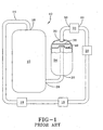
- FIG. 1 is a schematic view of a prior art air-conditioning system.
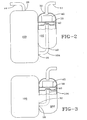
- FIG. 2 is a schematic view of a HVAC&R system of the present invention.
- FIG. 3 is a schematic view of another embodiment of the HVAC&R system of the present invention.
- Expansion device 18 may include a valve or series of valves which causes the fluid to expand, resulting in the lowering of the pressure and temperature of the fluid.
- the fluid exits expansion device 18 via conduit 14 primarily as a cool low-pressure liquid, with possibly some vaporous fluid, and is transported to an evaporator 20.
- the substantially cool low-pressure liquid enters into a heat-exchange relation with yet another fluid and undergoes a phase change to be converted to substantially a gas.
- This phase change of the fluid from a liquid to a gas is an endothermic transformation which absorbs heat from the other fluid in contact with evaporator 20.
- the volume of fluid entering into contact with evaporator 20 is enhanced or increased by use of other devices such a blower (not shown).
- the gas exiting evaporator 20 may include some liquid that was not converted in evaporator 20.
- the fluid is then transferred via conduit 14 to a filtering device 22 that preferably employs a desiccant (not shown) to remove any water that may be present in the fluid.
- the refrigerant vapor which may include liquid, from filtering device 22 is transported via conduit 14 to an accumulator 24.
- accumulator 24 any liquid that is present in the refrigerant is removed and the liquid is stored until it vaporizes and is re-circulated back into the air-conditioning system 10.
- the refrigerant vapor is drawn into the compressor to be compressed, and the cycle is repeated.
- the filter 22 is typically a separate unit, requiring installation within the air-conditioning system 10 by brazing inlet and outlet connections 34, 36.
- a compressor 100 and an accumulator 102 into a HVAC&R system similar to the AC system 10 shown in Fig. 1.
- Compressor 100 is preferably a rotary or swing link compressor, however, any compressor that requires an accumulator and/or a desiccant can be used.
- Accumulator 102 is integrally connected or attached to the shell or casing of compressor 100.
- a conduit 104 extends inside of accumulator 102 and is installed between accumulator outlet 32 and compressor inlet 26, thereby providing a pre-installed connection between accumulator outlet 32 and compressor inlet 26.
- accumulator 102 and compressor 100 are connected or attached by a mechanical fastening means or device, including straps, bolts, screws, brackets, adhesives, welds or any conventional method of securing components together.
- Accumulator 102 preferably employs a screen 38 and a baffle 40, each preferably adjacent accumulator inlet 30, to prevent particulate matter and liquid refrigerant from entering accumulator outlet 32 and traveling to compressor 100.
- a desiccant material 42 is placed between accumulator inlet 30 and screen 38 to remove any water that may be present in the refrigerant entering accumulator 102. Any accumulator configuration that can incorporate desiccant can be used. Any suitable desiccant material that is compatible with the refrigerant of the system can be used.
- conduit 104 is contained entirely within accumulator 202.
- accumulator outlet 32 is integral with compressor inlet 26, thereby providing conduit 104 further protection from damage using the accumulator housing.
Landscapes
- Engineering & Computer Science (AREA)
- Chemical & Material Sciences (AREA)
- Analytical Chemistry (AREA)
- Power Engineering (AREA)
- Physics & Mathematics (AREA)
- Mechanical Engineering (AREA)
- Thermal Sciences (AREA)
- General Engineering & Computer Science (AREA)
- Air-Conditioning For Vehicles (AREA)
- Fluid-Damping Devices (AREA)
- Compressor (AREA)
- Fats And Perfumes (AREA)
Claims (7)
- Verdichtungsanordnung zur Verwendung in einer Heiz-, Ventilations-, Klima- und Kühlanlage mit einem Kühlmittel, das durch die Anlage strömt, wobei die Verdichtungsanordnung umfasst:einen Verdichter (100) mit einem Verdichtergehäuse, der Kühlmitteldampf verdichtet, wobei der Verdichter einen Verdichtereinlass (26), der Kühlmitteldampf aufnimmt, und einen Verdichterauslass (28), der verdichteten Kühlmitteldampf vom Verdichter weiterleitet, aufweist;einen Speicher (102), der flüssiges Kühlmittel aus der Kühlmittelströmung entfernt und dem Verdichter Kühlmitteldampf liefert, wobei der Speicher einen Speichereinlass (30), der Kühlmittel aufnimmt, und einen Speicherauslass (32) in Fluidverbindung mit dem Verdichtereinlass aufweist, der Kühlmitteldampf zum Verdichter weiterleitet, wobei der Speicher (102) ein Gehäuse aufweist, das mit dem Verdichtergehäuse einstückig ist und mit ihm in Verbindung steht, um eine einzige Einheit für die Verdichtungsanordnung zu bilden;dadurch gekennzeichnet, dass der Speicherauslass (32) mit dem Verdichtereinlass (26) einstückig ist, und dass ein Trockenmittel (42) im Innern des Speichers zwischen dem Speichereinlass und -auslass zum Entfernen von Feuchtigkeit aus dem Kühlmittel angeordnet ist.
- Verdichtungsanordnung nach Anspruch 1, wobei die Verbindung zwischen dem Speicherauslass (32) und dem Verdichtereinlass (26) innerhalb des Speichers angeordnet ist.
- Verdichtungsanordnung nach Anspruch 2, wobei die einstückige Verbindung eine Leitung (104) ist.
- Verdichtungsanordnung nach einem der vorhergehenden Ansprüche, die weiterhin ein Sieb (38) oder eine Trennwand (40) umfasst, die an den Speichereinlass (30) angrenzt, um zu verhindern, dass Feststoffe in den Speicherauslass (32) eintreten.
- Verdichtungsanordnung nach einem der vorhergehenden Ansprüche, wobei das Trockenmittel zwischen dem Speichereinlass (30) und einem Sieb (38) angeordnet ist, um zu verhindern, dass Feststoffe in den Speicherauslass eintreten.
- Verdichtungsanordnung nach einem der vorhergehenden Ansprüche, wobei der Verdichter (100) von einer Rotationsart ist.
- Verdichtungsanordnung nach einem der vorhergehenden Ansprüche, wobei der Verdichter (100) von einer Schwungverbinderart ist.
Applications Claiming Priority (3)
| Application Number | Priority Date | Filing Date | Title |
|---|---|---|---|
| US10/331,916 US6708519B1 (en) | 2002-12-30 | 2002-12-30 | Accumulator with internal desiccant |
| US331916 | 2002-12-30 | ||
| PCT/US2003/041771 WO2004061379A1 (en) | 2002-12-30 | 2003-12-30 | Accumulator with internal desiccant |
Publications (2)
| Publication Number | Publication Date |
|---|---|
| EP1588109A1 EP1588109A1 (de) | 2005-10-26 |
| EP1588109B1 true EP1588109B1 (de) | 2007-06-20 |
Family
ID=31978104
Family Applications (1)
| Application Number | Title | Priority Date | Filing Date |
|---|---|---|---|
| EP03800412A Expired - Lifetime EP1588109B1 (de) | 2002-12-30 | 2003-12-30 | Akkumulator mit eingebautem trockenmittel |
Country Status (10)
| Country | Link |
|---|---|
| US (1) | US6708519B1 (de) |
| EP (1) | EP1588109B1 (de) |
| JP (1) | JP2006512559A (de) |
| CN (1) | CN1754074A (de) |
| AT (1) | ATE365302T1 (de) |
| AU (1) | AU2003300158A1 (de) |
| BR (1) | BR0317873A (de) |
| DE (1) | DE60314547T2 (de) |
| IL (1) | IL169455A (de) |
| WO (1) | WO2004061379A1 (de) |
Families Citing this family (8)
| Publication number | Priority date | Publication date | Assignee | Title |
|---|---|---|---|---|
| JP5764372B2 (ja) * | 2011-04-15 | 2015-08-19 | 株式会社不二工機 | アキュムレータ |
| JP5712775B2 (ja) * | 2011-05-09 | 2015-05-07 | カルソニックカンセイ株式会社 | アキュムレータ |
| US8950081B2 (en) * | 2011-06-17 | 2015-02-10 | Emerson Climate Technologies, Inc. | Compressor dehydration via sorbent technology |
| CN108626922B (zh) * | 2017-03-17 | 2020-12-04 | Lg电子株式会社 | 储液器 |
| KR102442917B1 (ko) * | 2017-03-17 | 2022-09-15 | 엘지전자 주식회사 | 어큐뮬레이터 |
| KR20180118397A (ko) * | 2017-04-21 | 2018-10-31 | 엘지전자 주식회사 | 어큐뮬레이터 |
| CN113945018A (zh) * | 2020-06-30 | 2022-01-18 | 上海海立电器有限公司 | 一种空调的制冷动力系统 |
| CN116753646B (zh) * | 2023-07-03 | 2025-09-02 | 广东美芝制冷设备有限公司 | 储液器、压缩机及制冷设备 |
Family Cites Families (33)
| Publication number | Priority date | Publication date | Assignee | Title |
|---|---|---|---|---|
| US1677804A (en) | 1923-01-29 | 1928-07-17 | Ubald R Loranger | Gas scrubber for refrigerating apparatus |
| US2594108A (en) | 1950-02-08 | 1952-04-22 | Woodbridge Dwight Elivi | Air drier |
| US3175342A (en) | 1963-01-16 | 1965-03-30 | Parker Hannifin Corp | Filter dryer unit for cleaning sealed refrigerating systems after motor burn outs |
| US3592563A (en) | 1968-12-30 | 1971-07-13 | Westinghouse Air Brake Co | Filter purging apparatus |
| GB1325881A (en) | 1969-08-12 | 1973-08-08 | Union Carbide Corp | Cryogenic separation of air |
| US4053398A (en) | 1976-02-26 | 1977-10-11 | Borg-Warner Corporation | Method and apparatus for water removal from oil in submersible motor environment |
| US4111005A (en) * | 1977-04-07 | 1978-09-05 | General Motors Corporation | Press-on plastic baffle for accumulator-dehydrator |
| US4174204A (en) * | 1978-08-04 | 1979-11-13 | Donaldson Company, Inc. | Pulse jet cleaned air filter assembly with integral air compressor |
| US4406593A (en) * | 1980-06-11 | 1983-09-27 | Tecumseh Products Company | Mounting spud arrangement for a hermetic compressor |
| DE3425735C2 (de) | 1984-07-12 | 1986-07-10 | Danfoss A/S, Nordborg | Kältemitteltrockner für eine Kälteanlage |
| US4581903A (en) * | 1984-08-23 | 1986-04-15 | Harry Kerry | Interchangeable suction accumulator and filter-drier |
| JPH0114780Y2 (de) | 1984-11-20 | 1989-04-28 | ||
| US4607503A (en) * | 1985-09-27 | 1986-08-26 | Tecumseh Products Company | Compressor mounted suction accumulator |
| JPS62162786A (ja) * | 1986-01-10 | 1987-07-18 | Sanyo Electric Co Ltd | スクロ−ル圧縮機 |
| US4959975A (en) | 1987-05-14 | 1990-10-02 | Conserve, Inc. | Heat pump system |
| US4888962A (en) * | 1989-01-06 | 1989-12-26 | Tecumseh Products Company | Suction accumulator strap |
| US5056336A (en) * | 1989-03-06 | 1991-10-15 | American Standard Inc. | Scroll apparatus with modified scroll profile |
| DE3907592A1 (de) | 1989-03-09 | 1990-09-13 | Duerr Dental Gmbh Co Kg | Druckluft- und unterdruck-versorgungseinheit |
| JPH04257671A (ja) * | 1991-02-08 | 1992-09-11 | Daikin Ind Ltd | 圧縮装置 |
| US5177982A (en) * | 1991-12-23 | 1993-01-12 | Ford Motor Company | Accumulator desiccant bag retaining clip |
| US5575833A (en) | 1992-09-25 | 1996-11-19 | Parker-Hannifin Corporation | Refrigerant recycling system and apparatus |
| EP0594431B1 (de) | 1992-10-23 | 1998-01-07 | Matsushita Refrigeration Company | Kältemittelkompressor und Kältesystem mit diesem Kompressor |
| US5507159A (en) * | 1994-04-25 | 1996-04-16 | Tecumseh Products Company | Suction accumulator vibration damper |
| US5458677A (en) | 1994-05-05 | 1995-10-17 | Alliedsignal Truck Brake Systems Company | Air dryer mechanism with flow regulated purge pressure |
| US5850743A (en) * | 1996-11-13 | 1998-12-22 | Tecumseh Products Company | Suction accumulator assembly |
| JP4019336B2 (ja) | 1998-03-18 | 2007-12-12 | 株式会社日立製作所 | エアコンプレッサ |
| US6132183A (en) * | 1998-11-23 | 2000-10-17 | Carrier Corporation | Compressor mounting |
| US6220050B1 (en) * | 1998-11-24 | 2001-04-24 | Tecumseh Products Company | Suction accumulator |
| JP2000265959A (ja) * | 1999-03-16 | 2000-09-26 | Daikin Ind Ltd | アキュムレータ一体型圧縮機 |
| US6202437B1 (en) * | 1999-05-19 | 2001-03-20 | Carrier Corporation | Suction accumulator pre-charged with oil |
| US6311514B1 (en) * | 2000-04-07 | 2001-11-06 | Automotive Fluid Systems, Inc. | Refrigeration accumulator having a matrix wall structure |
| US6494057B1 (en) * | 2000-07-20 | 2002-12-17 | Carrier Corporation | Combination accumulator filter drier |
| JP2002090004A (ja) * | 2000-09-20 | 2002-03-27 | Fujitsu General Ltd | アキュムレータ |
-
2002
- 2002-12-30 US US10/331,916 patent/US6708519B1/en not_active Expired - Lifetime
-
2003
- 2003-12-30 DE DE60314547T patent/DE60314547T2/de not_active Expired - Fee Related
- 2003-12-30 JP JP2004564935A patent/JP2006512559A/ja active Pending
- 2003-12-30 WO PCT/US2003/041771 patent/WO2004061379A1/en not_active Ceased
- 2003-12-30 AT AT03800412T patent/ATE365302T1/de not_active IP Right Cessation
- 2003-12-30 CN CN200380109941.9A patent/CN1754074A/zh active Pending
- 2003-12-30 AU AU2003300158A patent/AU2003300158A1/en not_active Abandoned
- 2003-12-30 BR BR0317873-0A patent/BR0317873A/pt not_active IP Right Cessation
- 2003-12-30 EP EP03800412A patent/EP1588109B1/de not_active Expired - Lifetime
-
2005
- 2005-06-29 IL IL169455A patent/IL169455A/en not_active IP Right Cessation
Non-Patent Citations (1)
| Title |
|---|
| None * |
Also Published As
| Publication number | Publication date |
|---|---|
| CN1754074A (zh) | 2006-03-29 |
| US6708519B1 (en) | 2004-03-23 |
| BR0317873A (pt) | 2005-12-06 |
| DE60314547T2 (de) | 2007-10-25 |
| DE60314547D1 (de) | 2007-08-02 |
| WO2004061379A1 (en) | 2004-07-22 |
| IL169455A (en) | 2008-11-03 |
| ATE365302T1 (de) | 2007-07-15 |
| AU2003300158A1 (en) | 2004-07-29 |
| JP2006512559A (ja) | 2006-04-13 |
| EP1588109A1 (de) | 2005-10-26 |
Similar Documents
| Publication | Publication Date | Title |
|---|---|---|
| US6698234B2 (en) | Method for increasing efficiency of a vapor compression system by evaporator heating | |
| EP1418395A2 (de) | Kühlungssystem | |
| GB2316738A (en) | A combined refrigerant accumulator and heat transfer unit | |
| JPH0650639A (ja) | 機能を失った冷却ユニットから冷媒を回収するための回路及び回収方法 | |
| EP1588109B1 (de) | Akkumulator mit eingebautem trockenmittel | |
| JP4776438B2 (ja) | 冷凍サイクル | |
| JPH08219590A (ja) | 受液器一体型冷媒凝縮器 | |
| JP3812582B2 (ja) | 受液器一体型冷媒凝縮器 | |
| US6494057B1 (en) | Combination accumulator filter drier | |
| CA1086518A (en) | Reversible-cycle closed-circuit refrigeration systems | |
| KR100524720B1 (ko) | 멀티 에어컨 시스템용 실내기 바이패스 장치 | |
| CN109186053B (zh) | 热回收装置及空调器 | |
| JPH03294750A (ja) | 冷凍装置 | |
| KR100531815B1 (ko) | 멀티 에어컨 시스템의 헤더 구조 | |
| JP3736809B2 (ja) | 空気調和機 | |
| WO2006065185A1 (en) | Arrangement and method relating to cooling systems | |
| JP2001194033A (ja) | 車両用空気調和装置 | |
| US20250381823A1 (en) | Thermal management module for a vehicle | |
| KR0137578Y1 (ko) | 히트펌프의 기액분리장치 | |
| KR200160408Y1 (ko) | 냉장고 | |
| JPH11142019A (ja) | 冷凍装置 | |
| JP4374755B2 (ja) | ヒートポンプシステム | |
| KR20080038784A (ko) | 자동차 공조장치용 소음기 | |
| JPH04283360A (ja) | 冷凍装置 | |
| CN104457029B (zh) | 压缩机组及包括该压缩机组的空调器 |
Legal Events
| Date | Code | Title | Description |
|---|---|---|---|
| PUAI | Public reference made under article 153(3) epc to a published international application that has entered the european phase |
Free format text: ORIGINAL CODE: 0009012 |
|
| 17P | Request for examination filed |
Effective date: 20050704 |
|
| AK | Designated contracting states |
Kind code of ref document: A1 Designated state(s): AT BE BG CH CY CZ DE DK EE ES FI FR GB GR HU IE IT LI LU MC NL PT RO SE SI SK TR |
|
| AX | Request for extension of the european patent |
Extension state: AL LT LV MK |
|
| DAX | Request for extension of the european patent (deleted) | ||
| GRAC | Information related to communication of intention to grant a patent modified |
Free format text: ORIGINAL CODE: EPIDOSCIGR1 |
|
| GRAP | Despatch of communication of intention to grant a patent |
Free format text: ORIGINAL CODE: EPIDOSNIGR1 |
|
| GRAS | Grant fee paid |
Free format text: ORIGINAL CODE: EPIDOSNIGR3 |
|
| GRAA | (expected) grant |
Free format text: ORIGINAL CODE: 0009210 |
|
| AK | Designated contracting states |
Kind code of ref document: B1 Designated state(s): AT BE BG CH CY CZ DE DK EE ES FI FR GB GR HU IE IT LI LU MC NL PT RO SE SI SK TR |
|
| PG25 | Lapsed in a contracting state [announced via postgrant information from national office to epo] |
Ref country code: LI Free format text: LAPSE BECAUSE OF FAILURE TO SUBMIT A TRANSLATION OF THE DESCRIPTION OR TO PAY THE FEE WITHIN THE PRESCRIBED TIME-LIMIT Effective date: 20070620 Ref country code: CH Free format text: LAPSE BECAUSE OF FAILURE TO SUBMIT A TRANSLATION OF THE DESCRIPTION OR TO PAY THE FEE WITHIN THE PRESCRIBED TIME-LIMIT Effective date: 20070620 |
|
| REG | Reference to a national code |
Ref country code: GB Ref legal event code: FG4D |
|
| REG | Reference to a national code |
Ref country code: CH Ref legal event code: EP |
|
| REG | Reference to a national code |
Ref country code: IE Ref legal event code: FG4D |
|
| REF | Corresponds to: |
Ref document number: 60314547 Country of ref document: DE Date of ref document: 20070802 Kind code of ref document: P |
|
| PG25 | Lapsed in a contracting state [announced via postgrant information from national office to epo] |
Ref country code: SE Free format text: LAPSE BECAUSE OF FAILURE TO SUBMIT A TRANSLATION OF THE DESCRIPTION OR TO PAY THE FEE WITHIN THE PRESCRIBED TIME-LIMIT Effective date: 20070920 |
|
| PG25 | Lapsed in a contracting state [announced via postgrant information from national office to epo] |
Ref country code: AT Free format text: LAPSE BECAUSE OF FAILURE TO SUBMIT A TRANSLATION OF THE DESCRIPTION OR TO PAY THE FEE WITHIN THE PRESCRIBED TIME-LIMIT Effective date: 20070620 |
|
| NLV1 | Nl: lapsed or annulled due to failure to fulfill the requirements of art. 29p and 29m of the patents act | ||
| REG | Reference to a national code |
Ref country code: CH Ref legal event code: PL |
|
| PG25 | Lapsed in a contracting state [announced via postgrant information from national office to epo] |
Ref country code: BE Free format text: LAPSE BECAUSE OF FAILURE TO SUBMIT A TRANSLATION OF THE DESCRIPTION OR TO PAY THE FEE WITHIN THE PRESCRIBED TIME-LIMIT Effective date: 20070620 |
|
| PG25 | Lapsed in a contracting state [announced via postgrant information from national office to epo] |
Ref country code: PT Free format text: LAPSE BECAUSE OF FAILURE TO SUBMIT A TRANSLATION OF THE DESCRIPTION OR TO PAY THE FEE WITHIN THE PRESCRIBED TIME-LIMIT Effective date: 20071120 Ref country code: NL Free format text: LAPSE BECAUSE OF FAILURE TO SUBMIT A TRANSLATION OF THE DESCRIPTION OR TO PAY THE FEE WITHIN THE PRESCRIBED TIME-LIMIT Effective date: 20070620 Ref country code: ES Free format text: LAPSE BECAUSE OF FAILURE TO SUBMIT A TRANSLATION OF THE DESCRIPTION OR TO PAY THE FEE WITHIN THE PRESCRIBED TIME-LIMIT Effective date: 20071001 Ref country code: SI Free format text: LAPSE BECAUSE OF FAILURE TO SUBMIT A TRANSLATION OF THE DESCRIPTION OR TO PAY THE FEE WITHIN THE PRESCRIBED TIME-LIMIT Effective date: 20070620 Ref country code: CZ Free format text: LAPSE BECAUSE OF FAILURE TO SUBMIT A TRANSLATION OF THE DESCRIPTION OR TO PAY THE FEE WITHIN THE PRESCRIBED TIME-LIMIT Effective date: 20070620 Ref country code: BG Free format text: LAPSE BECAUSE OF FAILURE TO SUBMIT A TRANSLATION OF THE DESCRIPTION OR TO PAY THE FEE WITHIN THE PRESCRIBED TIME-LIMIT Effective date: 20070920 |
|
| EN | Fr: translation not filed | ||
| PG25 | Lapsed in a contracting state [announced via postgrant information from national office to epo] |
Ref country code: SK Free format text: LAPSE BECAUSE OF FAILURE TO SUBMIT A TRANSLATION OF THE DESCRIPTION OR TO PAY THE FEE WITHIN THE PRESCRIBED TIME-LIMIT Effective date: 20070620 |
|
| PLBE | No opposition filed within time limit |
Free format text: ORIGINAL CODE: 0009261 |
|
| STAA | Information on the status of an ep patent application or granted ep patent |
Free format text: STATUS: NO OPPOSITION FILED WITHIN TIME LIMIT |
|
| PG25 | Lapsed in a contracting state [announced via postgrant information from national office to epo] |
Ref country code: GR Free format text: LAPSE BECAUSE OF FAILURE TO SUBMIT A TRANSLATION OF THE DESCRIPTION OR TO PAY THE FEE WITHIN THE PRESCRIBED TIME-LIMIT Effective date: 20070921 Ref country code: IT Free format text: LAPSE BECAUSE OF FAILURE TO SUBMIT A TRANSLATION OF THE DESCRIPTION OR TO PAY THE FEE WITHIN THE PRESCRIBED TIME-LIMIT Effective date: 20070620 Ref country code: DK Free format text: LAPSE BECAUSE OF FAILURE TO SUBMIT A TRANSLATION OF THE DESCRIPTION OR TO PAY THE FEE WITHIN THE PRESCRIBED TIME-LIMIT Effective date: 20070620 |
|
| 26N | No opposition filed |
Effective date: 20080325 |
|
| PG25 | Lapsed in a contracting state [announced via postgrant information from national office to epo] |
Ref country code: RO Free format text: LAPSE BECAUSE OF FAILURE TO SUBMIT A TRANSLATION OF THE DESCRIPTION OR TO PAY THE FEE WITHIN THE PRESCRIBED TIME-LIMIT Effective date: 20070620 |
|
| PG25 | Lapsed in a contracting state [announced via postgrant information from national office to epo] |
Ref country code: FR Free format text: LAPSE BECAUSE OF FAILURE TO SUBMIT A TRANSLATION OF THE DESCRIPTION OR TO PAY THE FEE WITHIN THE PRESCRIBED TIME-LIMIT Effective date: 20080222 Ref country code: MC Free format text: LAPSE BECAUSE OF NON-PAYMENT OF DUE FEES Effective date: 20071231 |
|
| GBPC | Gb: european patent ceased through non-payment of renewal fee |
Effective date: 20071230 |
|
| PG25 | Lapsed in a contracting state [announced via postgrant information from national office to epo] |
Ref country code: IE Free format text: LAPSE BECAUSE OF NON-PAYMENT OF DUE FEES Effective date: 20071231 |
|
| PG25 | Lapsed in a contracting state [announced via postgrant information from national office to epo] |
Ref country code: GB Free format text: LAPSE BECAUSE OF NON-PAYMENT OF DUE FEES Effective date: 20071230 |
|
| PG25 | Lapsed in a contracting state [announced via postgrant information from national office to epo] |
Ref country code: EE Free format text: LAPSE BECAUSE OF FAILURE TO SUBMIT A TRANSLATION OF THE DESCRIPTION OR TO PAY THE FEE WITHIN THE PRESCRIBED TIME-LIMIT Effective date: 20070620 |
|
| PG25 | Lapsed in a contracting state [announced via postgrant information from national office to epo] |
Ref country code: FI Free format text: LAPSE BECAUSE OF FAILURE TO SUBMIT A TRANSLATION OF THE DESCRIPTION OR TO PAY THE FEE WITHIN THE PRESCRIBED TIME-LIMIT Effective date: 20070620 |
|
| PGFP | Annual fee paid to national office [announced via postgrant information from national office to epo] |
Ref country code: DE Payment date: 20081126 Year of fee payment: 6 |
|
| PG25 | Lapsed in a contracting state [announced via postgrant information from national office to epo] |
Ref country code: CY Free format text: LAPSE BECAUSE OF FAILURE TO SUBMIT A TRANSLATION OF THE DESCRIPTION OR TO PAY THE FEE WITHIN THE PRESCRIBED TIME-LIMIT Effective date: 20070620 |
|
| PG25 | Lapsed in a contracting state [announced via postgrant information from national office to epo] |
Ref country code: LU Free format text: LAPSE BECAUSE OF NON-PAYMENT OF DUE FEES Effective date: 20071230 |
|
| PG25 | Lapsed in a contracting state [announced via postgrant information from national office to epo] |
Ref country code: HU Free format text: LAPSE BECAUSE OF FAILURE TO SUBMIT A TRANSLATION OF THE DESCRIPTION OR TO PAY THE FEE WITHIN THE PRESCRIBED TIME-LIMIT Effective date: 20071221 Ref country code: TR Free format text: LAPSE BECAUSE OF FAILURE TO SUBMIT A TRANSLATION OF THE DESCRIPTION OR TO PAY THE FEE WITHIN THE PRESCRIBED TIME-LIMIT Effective date: 20070620 |
|
| PG25 | Lapsed in a contracting state [announced via postgrant information from national office to epo] |
Ref country code: DE Free format text: LAPSE BECAUSE OF NON-PAYMENT OF DUE FEES Effective date: 20100701 |