EP1587138A2 - Einrichtung für die Montage von Halbleiterchips und Verfahren zum Ablösen eines Halbleiterchips von einer Folie - Google Patents
Einrichtung für die Montage von Halbleiterchips und Verfahren zum Ablösen eines Halbleiterchips von einer Folie Download PDFInfo
- Publication number
- EP1587138A2 EP1587138A2 EP04106169A EP04106169A EP1587138A2 EP 1587138 A2 EP1587138 A2 EP 1587138A2 EP 04106169 A EP04106169 A EP 04106169A EP 04106169 A EP04106169 A EP 04106169A EP 1587138 A2 EP1587138 A2 EP 1587138A2
- Authority
- EP
- European Patent Office
- Prior art keywords
- chip
- film
- semiconductor chip
- edge
- support surface
- Prior art date
- Legal status (The legal status is an assumption and is not a legal conclusion. Google has not performed a legal analysis and makes no representation as to the accuracy of the status listed.)
- Granted
Links
Images


Classifications
-
- G—PHYSICS
- G07—CHECKING-DEVICES
- G07F—COIN-FREED OR LIKE APPARATUS
- G07F9/00—Details other than those peculiar to special kinds or types of apparatus
- G07F9/02—Devices for alarm or indication, e.g. when empty; Advertising arrangements in coin-freed apparatus
-
- H—ELECTRICITY
- H10—SEMICONDUCTOR DEVICES; ELECTRIC SOLID-STATE DEVICES NOT OTHERWISE PROVIDED FOR
- H10P—GENERIC PROCESSES OR APPARATUS FOR THE MANUFACTURE OR TREATMENT OF DEVICES COVERED BY CLASS H10
- H10P72/00—Handling or holding of wafers, substrates or devices during manufacture or treatment thereof
- H10P72/04—Apparatus for manufacture or treatment
- H10P72/0442—Apparatus for placing on an insulating substrate, e.g. tape
-
- F—MECHANICAL ENGINEERING; LIGHTING; HEATING; WEAPONS; BLASTING
- F21—LIGHTING
- F21V—FUNCTIONAL FEATURES OR DETAILS OF LIGHTING DEVICES OR SYSTEMS THEREOF; STRUCTURAL COMBINATIONS OF LIGHTING DEVICES WITH OTHER ARTICLES, NOT OTHERWISE PROVIDED FOR
- F21V33/00—Structural combinations of lighting devices with other articles, not otherwise provided for
-
- G—PHYSICS
- G07—CHECKING-DEVICES
- G07F—COIN-FREED OR LIKE APPARATUS
- G07F11/00—Coin-freed apparatus for dispensing, or the like, discrete articles
- G07F11/02—Coin-freed apparatus for dispensing, or the like, discrete articles from non-movable magazines
- G07F11/04—Coin-freed apparatus for dispensing, or the like, discrete articles from non-movable magazines in which magazines the articles are stored one vertically above the other
- G07F11/16—Delivery means
- G07F11/165—Delivery means using xyz-picker or multi-dimensional article picking arrangements
- G07F11/1657—Delivery means using xyz-picker or multi-dimensional article picking arrangements the picking arrangements using suction
-
- H—ELECTRICITY
- H10—SEMICONDUCTOR DEVICES; ELECTRIC SOLID-STATE DEVICES NOT OTHERWISE PROVIDED FOR
- H10P—GENERIC PROCESSES OR APPARATUS FOR THE MANUFACTURE OR TREATMENT OF DEVICES COVERED BY CLASS H10
- H10P72/00—Handling or holding of wafers, substrates or devices during manufacture or treatment thereof
- H10P72/50—Handling or holding of wafers, substrates or devices during manufacture or treatment thereof for positioning, orientation or alignment
-
- F—MECHANICAL ENGINEERING; LIGHTING; HEATING; WEAPONS; BLASTING
- F21—LIGHTING
- F21Y—INDEXING SCHEME ASSOCIATED WITH SUBCLASSES F21K, F21L, F21S and F21V, RELATING TO THE FORM OR THE KIND OF THE LIGHT SOURCES OR OF THE COLOUR OF THE LIGHT EMITTED
- F21Y2115/00—Light-generating elements of semiconductor light sources
- F21Y2115/10—Light-emitting diodes [LED]
-
- H—ELECTRICITY
- H10—SEMICONDUCTOR DEVICES; ELECTRIC SOLID-STATE DEVICES NOT OTHERWISE PROVIDED FOR
- H10P—GENERIC PROCESSES OR APPARATUS FOR THE MANUFACTURE OR TREATMENT OF DEVICES COVERED BY CLASS H10
- H10P72/00—Handling or holding of wafers, substrates or devices during manufacture or treatment thereof
- H10P72/70—Handling or holding of wafers, substrates or devices during manufacture or treatment thereof for supporting or gripping
- H10P72/74—Handling or holding of wafers, substrates or devices during manufacture or treatment thereof for supporting or gripping using temporarily an auxiliary support
- H10P72/744—Details of chemical or physical process used for separating the auxiliary support from a device or a wafer
- H10P72/7442—Separation by peeling
- H10P72/7444—Separation by peeling using a peeling wedge, a knife or a bar
-
- Y—GENERAL TAGGING OF NEW TECHNOLOGICAL DEVELOPMENTS; GENERAL TAGGING OF CROSS-SECTIONAL TECHNOLOGIES SPANNING OVER SEVERAL SECTIONS OF THE IPC; TECHNICAL SUBJECTS COVERED BY FORMER USPC CROSS-REFERENCE ART COLLECTIONS [XRACs] AND DIGESTS
- Y10—TECHNICAL SUBJECTS COVERED BY FORMER USPC
- Y10T—TECHNICAL SUBJECTS COVERED BY FORMER US CLASSIFICATION
- Y10T156/00—Adhesive bonding and miscellaneous chemical manufacture
- Y10T156/11—Methods of delaminating, per se; i.e., separating at bonding face
- Y10T156/1121—Using vibration during delaminating
-
- Y—GENERAL TAGGING OF NEW TECHNOLOGICAL DEVELOPMENTS; GENERAL TAGGING OF CROSS-SECTIONAL TECHNOLOGIES SPANNING OVER SEVERAL SECTIONS OF THE IPC; TECHNICAL SUBJECTS COVERED BY FORMER USPC CROSS-REFERENCE ART COLLECTIONS [XRACs] AND DIGESTS
- Y10—TECHNICAL SUBJECTS COVERED BY FORMER USPC
- Y10T—TECHNICAL SUBJECTS COVERED BY FORMER US CLASSIFICATION
- Y10T156/00—Adhesive bonding and miscellaneous chemical manufacture
- Y10T156/11—Methods of delaminating, per se; i.e., separating at bonding face
- Y10T156/1126—Using direct fluid current against work during delaminating
- Y10T156/1132—Using vacuum directly against work during delaminating
-
- Y—GENERAL TAGGING OF NEW TECHNOLOGICAL DEVELOPMENTS; GENERAL TAGGING OF CROSS-SECTIONAL TECHNOLOGIES SPANNING OVER SEVERAL SECTIONS OF THE IPC; TECHNICAL SUBJECTS COVERED BY FORMER USPC CROSS-REFERENCE ART COLLECTIONS [XRACs] AND DIGESTS
- Y10—TECHNICAL SUBJECTS COVERED BY FORMER USPC
- Y10T—TECHNICAL SUBJECTS COVERED BY FORMER US CLASSIFICATION
- Y10T156/00—Adhesive bonding and miscellaneous chemical manufacture
- Y10T156/19—Delaminating means
- Y10T156/1922—Vibrating delaminating means
-
- Y—GENERAL TAGGING OF NEW TECHNOLOGICAL DEVELOPMENTS; GENERAL TAGGING OF CROSS-SECTIONAL TECHNOLOGIES SPANNING OVER SEVERAL SECTIONS OF THE IPC; TECHNICAL SUBJECTS COVERED BY FORMER USPC CROSS-REFERENCE ART COLLECTIONS [XRACs] AND DIGESTS
- Y10—TECHNICAL SUBJECTS COVERED BY FORMER USPC
- Y10T—TECHNICAL SUBJECTS COVERED BY FORMER US CLASSIFICATION
- Y10T156/00—Adhesive bonding and miscellaneous chemical manufacture
- Y10T156/19—Delaminating means
- Y10T156/1928—Differential fluid pressure delaminating means
- Y10T156/1944—Vacuum delaminating means [e.g., vacuum chamber, etc.]
Definitions
- the invention relates to a method for detaching a semiconductor chip from a film of the The preamble of claim 1 mentioned type and suitable for carrying out the method Device for mounting semiconductor chips.
- the semiconductor chips are typically mounted on a film held by a frame in the Experts also known as tape, provided for processing with such a mounting device.
- the semiconductor chips adhere to the foil.
- the frame with the slide is made of a sliding Wafer table added. Tactically, the wafer table is shifted so that a semiconductor chip after another at a first location A, and then the provided semiconductor chip taken from a chip gripper and placed at a second location B on a substrate.
- the Removal of the provided semiconductor chip from the film is done by one below the film arranged chip ejector (known in the art as the die ejector) supported. It supports in usually at least one needle disposed in the chip ejector, the detachment of the semiconductor chip of the foil.
- the thickness of the semiconductor chips to be detached decreases continuously.
- the thickness is in many Cases already only 100 microns, with a tendency to further reduced thicknesses of 75 to 50 Micrometers.
- the wafers are provided on their back with an adhesive layer.
- the Adhesion of the semiconductor chips on the film therefore increases.
- the one described above Technology that removes the semiconductor chips with the help of needles is theirs Border.
- the detachment of the film with vacuum according to US 4,921,564 no longer works:
- the Film can not be heated to the required temperature of 50 ° C to 65 ° C, as the Cement layer already cures at these temperatures, so that the semiconductor chip even better on the A method of the type mentioned in the preamble of claim 1 is known from US Pat. No.
- the invention is based on the object of a robust method for the detachment of the semiconductor chips to develop from a film in which adjacent semiconductor chips are not damaged.
- An inventive device for the assembly of thin semiconductor chips, on a film includes a wafer table which accommodates the film with the semiconductor chips, and a chip ejector, its surface facing the film one of the width of the semiconductor chips to be detached corresponding ramp having a detachment edge, at which the semiconductor chip detached from the film becomes.
- the surface of the ramp is concave and reaches a maximum at the separation edge Height of only about 0.3 millimeters.
- the surface is a cylindrical surface, since this one has constant curvature. This shape of the ramp makes the angle between the bottom of the semiconductor chip and the film at the detachment edge of the ramp and thereby increases the for the Detaching the film from the semiconductor chip necessary force reduced.
- the height of the peel edge on the specified height of only 0.3 to 0.4 millimeters can be reduced.
- a grooved support surface Next to the detachment edge There is a grooved support surface.
- the furrows are parallel to the stripping direction or orthogonal to the separation edge and can be acted upon by vacuum.
- the wafer table is in two displaceable orthogonal directions.
- the chip gripper has taken the semiconductor chip, the next semiconductor chip of the Detached film and be provided on the support surface for receiving by the chip gripper.
- the Wafertisch is therefore to the length of the semiconductor chips and the average width of the saw marks in the first direction shifted.
- the existing on the film semiconductor chips are processed row by row, each of the first semiconductor chip of a row according to the process steps 1 and 2 with respect to the ramp is aligned.
- the method for picking a thin semiconductor chip from a film is thus characterized from that the detachment of the semiconductor chip from the film and the picking up of the semiconductor chip by the chip gripper takes place in two independent, consecutive process steps. After detachment, the semiconductor chip lands again on the film. But because the big part of the Foil is drawn into the grooves of the support surface, the contact surface between the film and the Semiconductor chip significantly reduced. Accordingly, the adhesion of the semiconductor chip on the Reduced film and the semiconductor chip can be easily picked up by the chip gripper.
- the ramp with the detachment edge is preferably subjected to ultrasound, so that the detachment process can be supported by ultrasound. Furthermore, the height of the detachment edge is advantageous adjustable, so that the height can be reduced immediately before the semiconductor chip completely the film is solved.
- the wafer table is displaced and thus moved relative to the chip ejector.
- the chip ejector can be moved, as it only relies on a relative movement arrives at the wafer table and the chip ejector.
- the film increasingly dissolves from the bottom of the semiconductor chip, since they are from the vacuum in the Ridges of the support surface is pulled in until the film with the exception of pieces of film between the heads of the needles and the semiconductor chip is detached from the semiconductor chip.
- the method step 5A can be carried out per se as in the prior art, preferably according to the method described in the European patent application EP 1424722, here is explicitly referenced.
- a measure to avoid the distortion of the film is that the film in small steps remove, without the support surface is subjected to vacuum. This is repeated the vacuum lifted at the support surface, the wafer table by a fraction of the length of the semiconductor chip moved and then applied vacuum to the support surface. The film is thus piecewise on each of the withdrawn newly advanced length of the semiconductor chip.
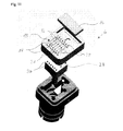
- FIG. 1 shows, in a simplified, schematic illustration, a device for mounting semiconductor chips 1, 1 ', 1 "on a substrate 2.
- the device has a displaceable wafer table 5, which receives the frame 3 and provides a semiconductor chip 1 after the other at a first location A.
- an inventive, in this example needleless chip ejector 6 is arranged.
- the chip ejector 6 serves to assist in the removal of the semiconductor chip 1 whose detachment from the film 4.
- the wafer stage 5 is displaceable in two orthogonal directions x and y.
- the film 4 is arranged such that the edges of the semiconductor chips 1, 1 ', 1 "' are approximately parallel to the directions x and y, respectively.”
- the device further comprises a chip gripper 7 for transporting the semiconductor chip 1 provided at the first location A to one located on the substrate 2 at the second location B.
- the chip gripper 7 is part of a liftable and lowerable bondhead 8.
- the bondhead 8 and the chip gripper 7 are combined between the location A and the location B (or several locations B 1 , B 2 , etc.) moved back and forth.
- Fig. 2 shows the chip ejector 6 in plan view, i. the film 4 facing surface 9 of the Chip ejector 6.
- Fig. 3 shows the chip ejector 6 in a section along the line I-I of FIG. 2.
- the surface 9 of the chip ejector 6 includes a recess 10 into which one with vacuum acted upon bore 11 opens, and provided with parallel grooves 12 Support surface 13.
- the grooves 12 extend in the x direction and the tips 14 of the grooves 12 are flush with the surface 9 of the chip ejector 6.
- insert 15 which includes a ramp 16 with a concave surface 17.
- the one side of the ramp 16 forms a protruding peel edge 18 on which the film 4 from Semiconductor chip 1 is detached.
- the opposite side 19 of the ramp 16 is flush with the Surface 9 of the chip ejector 6.
- the concave surface 17 is the surface of a Cylinder whose longitudinal axis is parallel to the separation edge 18 and, for example, a radius of 8 millimeters.
- the width B of the ramp 16 corresponds approximately to the width of the to be replaced Semiconductor chips.
- the height difference ⁇ H between the detachment edge 18 and the support surface 13 is about 0.3 millimeters. It is important that the separation edge 18 forms an abrupt transition to which the Semiconductor chips in the feed of the wafer table 5 in the x direction can not adapt.
- the Release edge 18 runs parallel to the y-direction.
- the place A (Fig. 1) is located in the center of Support surface 13.
- the formation of the surface 17 of the ramp 16 as a concave surface causes the angle ⁇ , the enclose tangent 21 and vertical 22 applied to the concave surface at the separation edge 18, can be chosen significantly smaller than 90 °.
- FIGS. 4 to 9 show successive snapshots during the Removal process and the subsequent picking process.
- FIGS. 4 to 9 show only those for the Understanding the Erfmdung necessary elements, namely the ramp 16 and the support surface 13, and the Foil 4 and successively detached semiconductor chips 1, 1 'and 1 "of a same row of the wafer.
- the wafer table is positioned so that a front edge of the first to be detached semiconductor chip 1 of a row of the wafer in parallel and along the detachment edge 18th the ramp 16 runs and that the first to be detached semiconductor chip 1 of this series with respect to the lateral edges 20 ( Figure 2) of the ramp 16 is centered.
- the grooves 12 of the support surface 13 applied with vacuum, so that the film 4 is pulled in this area in the grooves 12. This state is shown in FIG. 4.
- the wafer table 5 is now in the x-direction by a predetermined Distance ⁇ L advanced.
- the film 4 is pulled over the detachment edge 18 of the ramp 16. Of the Semiconductor chip 1 is moved.
- FIGS. 5 to 8 show successive snapshots during this feed.
- the geometry of the detachment edge 18 characterizes the semiconductor chip 1 detached from the film 4 and the detached part is inclined in the Air (Fig. 5, 6). As soon as the rear end of the semiconductor chip 1 reaches the detachment edge 18 (FIG. 7), it rotates the semiconductor chip 1 due to gravity around its rear edge and falls on the film 4 on the support surface 13.
- the first detached semiconductor chip 1 is now on foil 4 above the support surface 13 ready for the Pickup by the chip gripper 7.
- the position and orientation of this semiconductor chip 1 are now measured by a camera. If the deviation of the measured actual position from the desired position exceeds a predetermined tolerance limit, the wafer table 5 is shifted until the deviation the actual position of the semiconductor chip 1 of the desired position is within the predetermined tolerance limit. This process step has nothing to do with the actual removal process from the film.
- the Device is now ready for the chip gripper 7 to receive the first semiconductor chip 1 from the film 4 and place on the substrate 2 ( Figure 1).
- FIG. 9 shows the state immediately after Recording of the semiconductor chip 1 by the chip gripper 7.
- the described embodiment is designed such that the semiconductor chips 1 are provided at a fixed location A for the pickup by the chip gripper 7.
- the mounting device can also be designed such that the semiconductor chips are provided at different locations A 1 , A 2 , etc., and picked up by the chip gripper 7.
- FIG. 10 shows a further exemplary embodiment of the chip ejector 6, in which the height difference ⁇ H between the detaching edge 18 and the support surface 13 can be adjusted by means of a piston 24 which can be moved up and down by a drive 23.
- the piston 24 is disposed in the vicinity of the detachment edge 18, so that the ramp 16 during lifting of the piston 24 is rotated about the detachment edge 18 diagonally opposite edge 25, so that the Abttesskante 18 opposite edge 26 of the ramp 16 flush with the surface.
- 9 of the chip ejector 6 remains. This design allows an optimal adaptation of the height difference ⁇ H to the properties of the film.
- this embodiment makes it possible to refine the detachment method, since in step 4 the height difference ⁇ H initially has a predetermined value ⁇ H 1 until the state shown in FIG. 6 is reached. Now the piston 24 is lowered so that the height difference ⁇ H has a smaller value ⁇ H 2 . The height difference AH 2 is maintained at least as long until the illustrated in Fig. 7 state is reached where the semiconductor chip 1 rotates by gravity about its rear edge, wherein it is completely detached from the foil 4 and due to the gravity on the Support surface 13 falls. Subsequently, the piston 24 is raised again, so that the height difference ⁇ H again has the value ⁇ H 1 . The value ⁇ H 2 can also be zero.
- the insert 15 is preferably directly or optionally via the piston 24 with a Ultrasonic generator 27 coupled so that the detachment process can be supported with ultrasound. Also possible is a construction in which the entire chip ejector 6 is subjected to ultrasound becomes.
- Fig. 11 shows an exploded view of an embodiment of the chip ejector 6 with a Needle block 28.
- the tips 14 between the grooves 12 include holes 29 through which the needles 30 of the needle block 28, respectively.
- the grooves 12 also contain holes 31, which with Vacuum can be acted upon. In the assembled state, the needle block 28 and the ramp 16 raised and lowered.
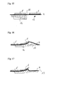
- Figs. 12 and 13 show the use of the needles 30 in principle, without details.
- the semiconductor chip 1 lies on the film 4 above the support surface 13 of the chip ejector 6.
- the chip gripper 7 is ready to order to receive the semiconductor chip 1.
- the needle block 28 is raised in the z-direction so that the needles 30 lift the film 4 locally without piercing it. This state is shown in FIG. 12.
- the chip gripper 7 and the needle block 28 continue together raised.
- the film 4 largely dissolves from the underside of the semiconductor chip 1, since the Vacuum the film 4 between the needles 30 pulls down into the grooves 12.
- the Movement of the needle block 28 stopped. This condition is shown in FIG. If the chip gripper 7 is further raised, then dissolves the semiconductor chip 1 finally from the film 4. In this For example, the tips of the needles 30 are not pointed but round, such that they do not support the film 4 pierce.
- Needle block 28 may be per se employed as is conventional in the art.
- the applied in the European patent application EP 1424722 method is preferred.
Landscapes
- Physics & Mathematics (AREA)
- General Physics & Mathematics (AREA)
- Engineering & Computer Science (AREA)
- General Engineering & Computer Science (AREA)
- Container, Conveyance, Adherence, Positioning, Of Wafer (AREA)
- Die Bonding (AREA)
Abstract
Description
- Da der Höhenunterschied an der Ablösekante der Rampe mit typischerweise 0.3 Millimetern, höchstens 0.4 Millimetern, sehr gering ist, werden benachbarte Halbleiterchips nicht beschädigt, selbst wenn ihr Rand ebenfalls über die Rampe bewegt wird.
- Da der Chipgreifer das Ablösen des Halbleiterchips von der Folie nicht unterstützen muss, ist die für einen Bondzyklus benötigte Zeit unabhängig vom Ablöseprozess.
- Da die Stützfläche mit den Furchen benachbarte Halbleiterchips nicht stört, kann die Stützfläche grossflächig ausgebildet sein, so dass sie sowohl für kleine als auch für grosse Halbleiterchips die gleiche sein kann.
- Die Breite der Rampe entspricht im Idealfall der Breite der Halbleiterchips. Die Rampe ist deshalb bevorzugt als auswechselbares Einlegeteil ausgebildet, das in eine mit Vakuum beaufschlagbare Ausnehmung des Chip-Auswerfers eingelegt wird.
- Fig. 1
- eine Einrichtung zur Montage von Halbleiterchips mit einem erfindungsgemässen Chip-Auswerfer,
- Fig. 2
- den Chip-Auswerfer in Aufsicht,
- Fig. 3
- den Chip-Auswerfer in einem Schnitt entlang der Linie I-I der Fig. 2,
- Fig. 4-9
- aufeinanderfolgende Momentaufnahmen während des Ablösens des Halbleiterchips von einer Folie und der Aufnahme des abgelösten Halbleiterchips mittels eines Chipgreifers gemäss einem ersten Verfahren,
- Fig. 10
- ein weiteres Beispiel des Chip-Auswerfers,
- Fig. 11
- einen Chip-Auswerfer mit einem Nadelblock,
- Fig. 12, 13
- die Aufnahme des Halbleiterchips mit Unterstützung von Nadeln, und
- Fig. 14-17
- Momentaufnahmen während des Ablösens des Halbleiterchips gemäss weiteren Verfahren.
Claims (11)
- Verfahren zum Ablösen eines Halbleiterchips (1) von einer Folie (4) und Aufnehmen des Halbleiterchips (1) von der Folie (4) mit einem Chipgreifer (7), wobei die Folie (4) auf einem verschiebbaren Wafertisch (5) fixiert ist und ein Teil der Folie (4) auf einer Oberfläche (9) eines Chip-Auswerfers (6) aufliegt, dadurch gekennzeichnet, dass der Wafertisch (5) relativ zum Chip-Auswerfer (6) verschoben wird, um die Folie (4) über eine von der Oberfläche (9) des Chip-Auswerfers (6) hervorstehende Ablösekante (18) zu ziehen, wobei die Ablösekante (18) eine Rampe (16) begrenzt, deren Oberfläche (17) konkav ausgebildet ist, wobei sich der Halbleiterchip (1) vorübergehend mindestens teilweise von der Folie (4) löst und auf der Folie (4) oberhalb einer Stützfläche (13) landet, die mit Vakuum beaufschlagbare Furchen (12) aufweist, und dass der Chipgreifer (7) den auf der Stützfläche (13) bereitliegenden Halbleiterchip (1) aufnimmt.
- Verfahren nach Anspruch 1, dadurch gekennzeichnet, dass die Furchen (12) der Stützfläche (13) während der Relativverschiebung von Wafertisch (5) und Chip-Auswerfer (6) mit Vakuum beaufschlagt sind.
- Verfahren nach Anspruch 2, dadurch gekennzeichnet, dass die Höhe der Ablösekante (18) relativ zur Oberfläche (9) reduziert wird, bevor die Folie (4) vollständig vom Halbleiterchip (1) gelöst ist.
- Verfahren nach Anspruch 1, dadurch gekennzeichnet, dass abwechslungsweise der Wafertisch (5) relativ zum Chip-Auswerfer (6) verschoben wird, ohne dass die Furchen (12) der Stützfläche (13) mit Vakuum beaufschlagt sind, und die Furchen (12) der Stützfläche (13) mit Vakuum beaufschlagt werden, während der Wafertisch (5) stillsteht, wobei der Wafertisch (5) jeweils um einen Bruchteil der Länge des Halbleiterchips (1) verschoben wird, und dass diese Schritte mehrfach wiederholt werden.
- Verfahren nach einem der Ansprüche 1 bis 4, dadurch gekennzeichnet, dass die Ablösung des Halbleiterchips (1) mit Ultraschall unterstützt wird.
- Einrichtung für die Montage von Halbleiterchips, die auf einer Folie (4) haften, mit einem verschiebbaren Wafertisch (5) für die Aufnahme der Folie (4), mit einem Chip-Auswerfer (6) und mit einem Chipgreifer (7) für das Aufnehmen eines Halbleiterchips (1) von der Folie (4) und Platzieren des Halbleiterchips (1) auf einem Substrat (2), dadurch gekennzeichnet, dass der Chip-Auswerfer (6) eine Rampe (16), deren Oberfläche (17) konkav ausgebildet ist und an einer von der Oberfläche (9) des Chip-Auswerfers (6) hervorstehenden Ablösekante (18) endet, und eine neben der Ablösekante (18) angeordnete Stützfläche (13) mit Furchen (12), die mit Vakuum beaufschlagbar sind, aufweist und dass der Chipgreifer (7) den auf der Stützfläche (13) bereitgestellten Halbleiterchip (1) aufnimmt.
- Einrichtung nach Anspruch 6, dadurch gekennzeichnet, dass die Ablösekante (18) um höchstens 0.4 Millimeter von der Oberfläche (9) des Chip-Auswerfers (6) hervorsteht.
- Einrichtung nach Anspruch 6 oder 7, dadurch gekennzeichnet, dass die Furchen (12) orthogonal zur Ablösekante (18) verlaufen.
- Einrichtung nach einem der Ansprüche 6 bis 8, dadurch gekennzeichnet, dass die konkave Oberfläche (17) der Rampe (16) die Oberfläche eines Zylinders ist, dessen Längsachse parallel zur Ablösekante (18) verläuft.
- Einrichtung nach einem der Ansprüche 6 bis 9, dadurch gekennzeichnet, dass die Höhe der Ablösekante (18) verstellbar ist.
- Einrichtung nach einem der Ansprüche 6 bis 10, dadurch gekennzeichnet, dass die Rampe (16) mit Ultraschall beaufschlagbar ist.
Priority Applications (8)
| Application Number | Priority Date | Filing Date | Title |
|---|---|---|---|
| EP04106169A EP1587138B1 (de) | 2004-04-13 | 2004-11-29 | Einrichtung für die Montage von Halbleiterchips und Verfahren zum Ablösen eines Halbleiterchips von einer Folie |
| SG200501843A SG116586A1 (en) | 2004-04-13 | 2005-03-23 | Method for detaching a semiconductor chip from a foiland apparatus for mounting semiconductor chips. |
| TW094110487A TWI254346B (en) | 2004-04-13 | 2005-04-01 | Method for detaching a semiconductor chip from a foil and apparatus for mounting semiconductor chip |
| MYPI20051561A MY139253A (en) | 2004-04-13 | 2005-04-07 | Apparatus for mounting of semi-conductor chips and method for stripping of a semi-conductor chip from a film |
| US11/101,750 US7238593B2 (en) | 2004-04-13 | 2005-04-08 | Method for detaching a semiconductor chip from a foil and device for mounting semiconductor chips |
| KR1020050030505A KR101143227B1 (ko) | 2004-04-13 | 2005-04-12 | 포일에서 반도체칩을 분리하는 방법 및 반도체칩 장착장치 |
| JP2005114075A JP4712424B2 (ja) | 2004-04-13 | 2005-04-12 | 半導体チップをフォイルから取り外す方法、及び半導体チップを実装するための装置 |
| US11/805,661 US7719125B2 (en) | 2004-04-13 | 2007-05-23 | Method for detaching a semiconductor chip from a foil and device for mounting semiconductor chips |
Applications Claiming Priority (5)
| Application Number | Priority Date | Filing Date | Title |
|---|---|---|---|
| EP04101498 | 2004-04-13 | ||
| EP41014986 | 2004-04-13 | ||
| EP04103054 | 2004-06-29 | ||
| EP41030545 | 2004-06-29 | ||
| EP04106169A EP1587138B1 (de) | 2004-04-13 | 2004-11-29 | Einrichtung für die Montage von Halbleiterchips und Verfahren zum Ablösen eines Halbleiterchips von einer Folie |
Publications (3)
| Publication Number | Publication Date |
|---|---|
| EP1587138A2 true EP1587138A2 (de) | 2005-10-19 |
| EP1587138A3 EP1587138A3 (de) | 2006-07-12 |
| EP1587138B1 EP1587138B1 (de) | 2007-05-30 |
Family
ID=34929964
Family Applications (1)
| Application Number | Title | Priority Date | Filing Date |
|---|---|---|---|
| EP04106169A Expired - Lifetime EP1587138B1 (de) | 2004-04-13 | 2004-11-29 | Einrichtung für die Montage von Halbleiterchips und Verfahren zum Ablösen eines Halbleiterchips von einer Folie |
Country Status (7)
| Country | Link |
|---|---|
| US (2) | US7238593B2 (de) |
| EP (1) | EP1587138B1 (de) |
| JP (1) | JP4712424B2 (de) |
| KR (1) | KR101143227B1 (de) |
| MY (1) | MY139253A (de) |
| SG (1) | SG116586A1 (de) |
| TW (1) | TWI254346B (de) |
Families Citing this family (18)
| Publication number | Priority date | Publication date | Assignee | Title |
|---|---|---|---|---|
| JP2009064938A (ja) * | 2007-09-06 | 2009-03-26 | Shinkawa Ltd | 半導体ダイのピックアップ装置及びピックアップ方法 |
| KR101046520B1 (ko) | 2007-09-07 | 2011-07-04 | 어플라이드 머티어리얼스, 인코포레이티드 | 내부 챔버 상의 부산물 막 증착을 제어하기 위한 pecvd 시스템에서의 소스 가스 흐름 경로 제어 |
| WO2009056469A1 (en) * | 2007-10-31 | 2009-05-07 | Oerlikon Assembly Equipment Ag, Steinhausen | Foil perforating needle for detaching a small die from a foil |
| TWI427713B (zh) * | 2008-10-23 | 2014-02-21 | Gallant Prec Machining Co Ltd | 晶片與膠膜分離方法與晶片取出方法 |
| MY150953A (en) * | 2008-11-05 | 2014-03-31 | Esec Ag | Die-ejector |
| KR20110086698A (ko) * | 2008-11-12 | 2011-07-29 | 에섹 에스에이 | 테이프로부터 반도체 칩을 탈착 및 제거하기 위한 방법 |
| SG163493A1 (en) | 2009-01-22 | 2010-08-30 | Esec Ag | Die ejector |
| JP4397429B1 (ja) * | 2009-03-05 | 2010-01-13 | 株式会社新川 | 半導体ダイのピックアップ装置及びピックアップ方法 |
| US8141612B2 (en) * | 2009-04-02 | 2012-03-27 | Asm Assembly Automation Ltd | Device for thin die detachment and pick-up |
| US8702904B2 (en) * | 2011-02-09 | 2014-04-22 | Branson Ultrasonics Corporation | Method and apparatus for separating laminations |
| JP5669137B2 (ja) * | 2011-03-01 | 2015-02-12 | 富士機械製造株式会社 | ダイピックアップ装置 |
| JP2013065712A (ja) * | 2011-09-16 | 2013-04-11 | Hitachi High-Tech Instruments Co Ltd | ダイボンダ及びボンディング方法 |
| JP2013065731A (ja) * | 2011-09-19 | 2013-04-11 | Hitachi High-Tech Instruments Co Ltd | ダイボンダ及びボンディング方法 |
| JP2015065367A (ja) * | 2013-09-26 | 2015-04-09 | 株式会社テセック | 剥離装置およびピックアップシステム |
| US20160167948A1 (en) * | 2014-12-15 | 2016-06-16 | W. L. Gore & Associates, Inc. | Vent Attachment System For Micro-Electromechanical Systems |
| IT201600105300A1 (it) * | 2016-10-19 | 2018-04-19 | Manz Italy Srl | Metodo e apparato di lavorazione |
| US20190308270A1 (en) * | 2018-04-06 | 2019-10-10 | Sunpower Corporation | Systems for laser assisted metallization of substrates |
| CN112038280B (zh) * | 2020-07-24 | 2022-07-29 | 华为技术有限公司 | 一种芯片转移方法、电子设备 |
Family Cites Families (21)
| Publication number | Priority date | Publication date | Assignee | Title |
|---|---|---|---|---|
| DE200834C (de) | ||||
| US4778326A (en) | 1983-05-24 | 1988-10-18 | Vichem Corporation | Method and means for handling semiconductor and similar electronic devices |
| JPS60114205A (ja) * | 1983-11-25 | 1985-06-20 | ワイケイケイ株式会社 | 隠しスライドファスナ−チェ−ンのスペ−ス形成方法及び装置 |
| US4921564A (en) | 1988-05-23 | 1990-05-01 | Semiconductor Equipment Corp. | Method and apparatus for removing circuit chips from wafer handling tape |
| DE69001797T2 (de) * | 1989-12-08 | 1994-01-27 | Sumitomo Electric Industries | Aufnahmeverfahren und -apparat für einen chipähnlichen Teil. |
| JPH04320046A (ja) | 1991-04-18 | 1992-11-10 | Fujitsu Ltd | 半導体チップのピックアップ装置 |
| KR100278137B1 (ko) * | 1997-09-04 | 2001-01-15 | 가나이 쓰도무 | 반도체소자의 탑재방법 및 그 시스템, 반도체소자 분리장치 및ic카드의 제조방법 |
| US6039833A (en) * | 1998-03-04 | 2000-03-21 | Lucent Technologies Inc. | Method and apparatus for component pickup |
| US5966903A (en) * | 1998-05-27 | 1999-10-19 | Lucent Technologies Inc. | High speed flip-chip dispensing |
| JP3209736B2 (ja) * | 1999-11-09 | 2001-09-17 | エヌイーシーマシナリー株式会社 | ペレットピックアップ装置 |
| JP4021614B2 (ja) * | 2000-12-11 | 2007-12-12 | 株式会社東芝 | 半導体素子のピックアップ用治具、半導体素子のピックアップ装置、半導体素子のピックアップ方法、半導体装置の製造方法及び半導体装置の製造装置 |
| JP4482243B2 (ja) | 2001-03-13 | 2010-06-16 | 株式会社新川 | ダイのピックアップ方法及びピックアップ装置 |
| JP3789802B2 (ja) * | 2001-10-19 | 2006-06-28 | 富士通株式会社 | 半導体装置の製造方法 |
| US6889427B2 (en) * | 2002-02-15 | 2005-05-10 | Freescale Semiconductor, Inc. | Process for disengaging semiconductor die from an adhesive film |
| JP4128843B2 (ja) * | 2002-10-16 | 2008-07-30 | 古河電気工業株式会社 | 半導体チップ製造方法 |
| US20040105750A1 (en) | 2002-11-29 | 2004-06-03 | Esec Trading Sa, A Swiss Corporation | Method for picking semiconductor chips from a foil |
| US6896762B2 (en) * | 2002-12-18 | 2005-05-24 | Industrial Technology Research Institute | Separation method for object and glue membrane |
| US7240422B2 (en) * | 2004-05-11 | 2007-07-10 | Asm Assembly Automation Ltd. | Apparatus for semiconductor chip detachment |
| US20050274457A1 (en) * | 2004-05-28 | 2005-12-15 | Asm Assembly Automation Ltd. | Peeling device for chip detachment |
| US7238258B2 (en) * | 2005-04-22 | 2007-07-03 | Stats Chippac Ltd. | System for peeling semiconductor chips from tape |
| JP4320046B1 (ja) | 2008-04-24 | 2009-08-26 | 日本インテリジェンス株式会社 | 機器探索システム及びその制御方法 |
-
2004
- 2004-11-29 EP EP04106169A patent/EP1587138B1/de not_active Expired - Lifetime
-
2005
- 2005-03-23 SG SG200501843A patent/SG116586A1/en unknown
- 2005-04-01 TW TW094110487A patent/TWI254346B/zh not_active IP Right Cessation
- 2005-04-07 MY MYPI20051561A patent/MY139253A/en unknown
- 2005-04-08 US US11/101,750 patent/US7238593B2/en not_active Expired - Fee Related
- 2005-04-12 KR KR1020050030505A patent/KR101143227B1/ko not_active Expired - Fee Related
- 2005-04-12 JP JP2005114075A patent/JP4712424B2/ja not_active Expired - Fee Related
-
2007
- 2007-05-23 US US11/805,661 patent/US7719125B2/en not_active Expired - Fee Related
Also Published As
| Publication number | Publication date |
|---|---|
| JP4712424B2 (ja) | 2011-06-29 |
| JP2005303308A (ja) | 2005-10-27 |
| EP1587138B1 (de) | 2007-05-30 |
| US20050224965A1 (en) | 2005-10-13 |
| TWI254346B (en) | 2006-05-01 |
| MY139253A (en) | 2009-09-30 |
| EP1587138A3 (de) | 2006-07-12 |
| KR101143227B1 (ko) | 2012-05-18 |
| TW200537584A (en) | 2005-11-16 |
| US7719125B2 (en) | 2010-05-18 |
| SG116586A1 (en) | 2005-11-28 |
| KR20060045639A (ko) | 2006-05-17 |
| US20070228539A1 (en) | 2007-10-04 |
| US7238593B2 (en) | 2007-07-03 |
Similar Documents
| Publication | Publication Date | Title |
|---|---|---|
| EP1587138B1 (de) | Einrichtung für die Montage von Halbleiterchips und Verfahren zum Ablösen eines Halbleiterchips von einer Folie | |
| EP2184765B1 (de) | Chip-Auswerfer | |
| AT506622B1 (de) | Vorrichtung und verfahren zum aufbringen und/oder ablösen eines wafers auf einen/von einem träger | |
| EP2359398B1 (de) | Verfahren zum ablösen und entnehmen eines halbleiterchips von einer folie | |
| DE102013103100B4 (de) | Verfahren zum Ablösen eines Halbleiterchips von einer Folie | |
| DE60316575T2 (de) | Verfahren und vorrichtung zum aufnehmen von halbleiterchips sowie dazu verwendbares saugung ablöswerkzeug | |
| DE102012013370B4 (de) | Montagevorrichtung und Verfahren zum Fixieren einer Nadel in einem Nadelhalter einer Ausstoßvorrichtung zum Abheben eines Chips von einem Trägermaterial | |
| CH697213A5 (de) | Verfahren und Vorrichtung zum Ablösen eines auf eine flexible Folie geklebten Bauteils. | |
| AT503848A2 (de) | Handhabungsvorrichtung sowie handhabungsverfahren für wafer | |
| CH697146A5 (de) | Greifvorrichtung zur Handhabung von Wafern. | |
| EP3443587B1 (de) | Vorrichtung, system und verfahren zum ausrichten elektronischer bauteile | |
| EP0388398B1 (de) | Vorrichtung zum Abnehmen eines flächigen Werkstückes von einer anklebenden Unterfolie | |
| WO2002035591A1 (de) | Verfahren zum aufbringen eines substrats | |
| CH699851A1 (de) | Chip-Auswerfer und Verfahren zum Ablösen und Entnehmen eines Halbleiterchips von einer Folie. | |
| EP1490894A1 (de) | Verfahren zum verarbeiten von elektrischen bauelementen, insbesondere von halbleiterchips, sowie vorrichtung zum durchf hren des verfahrens | |
| EP0521066A1 (de) | Verfahren und vorrichtung zum vereinzeln von gestapelten textilen zuschnitten. | |
| EP1049140B1 (de) | Einrichtung und Verfahren zur Montage von Halbleiterchips auf einem Substrat | |
| DE102009035099B4 (de) | Vorrichtung und Verfahren zum Abheben von Bauteilen von einem Träger | |
| DE102006059809B4 (de) | Vorrichtung und Verfahren zum Vereinzeln und Transportieren von Substraten | |
| WO2010094502A1 (de) | Vorrichtung zum vereinzeln von scheibenförmigen elementen | |
| DE19752582C2 (de) | Ablösevorrichtung für Mikrobauteile | |
| EP1321969A2 (de) | Verfahren und Vorrichtung zum Handhaben von Halbleiterscheiben | |
| DE102023201111A1 (de) | Wafertransferverfahren und wafertransfervorrichtung | |
| WO1998015971A1 (de) | Greifvorrichtung für wafer | |
| AT516595B1 (de) | Vorrichtung und Verfahren zum Aufbringen und/oder Ablösen eines Wafers auf einen/von einem Träger |
Legal Events
| Date | Code | Title | Description |
|---|---|---|---|
| PUAI | Public reference made under article 153(3) epc to a published international application that has entered the european phase |
Free format text: ORIGINAL CODE: 0009012 |
|
| AK | Designated contracting states |
Kind code of ref document: A2 Designated state(s): AT BE BG CH CY CZ DE DK EE ES FI FR GB GR HU IE IS IT LI LU MC NL PL PT RO SE SI SK TR |
|
| AX | Request for extension of the european patent |
Extension state: AL HR LT LV MK YU |
|
| 17P | Request for examination filed |
Effective date: 20060330 |
|
| PUAL | Search report despatched |
Free format text: ORIGINAL CODE: 0009013 |
|
| AK | Designated contracting states |
Kind code of ref document: A3 Designated state(s): AT BE BG CH CY CZ DE DK EE ES FI FR GB GR HU IE IS IT LI LU MC NL PL PT RO SE SI SK TR |
|
| AX | Request for extension of the european patent |
Extension state: AL HR LT LV MK YU |
|
| GRAP | Despatch of communication of intention to grant a patent |
Free format text: ORIGINAL CODE: EPIDOSNIGR1 |
|
| AKX | Designation fees paid |
Designated state(s): AT CH DE FR GB IT LI |
|
| GRAS | Grant fee paid |
Free format text: ORIGINAL CODE: EPIDOSNIGR3 |
|
| GRAA | (expected) grant |
Free format text: ORIGINAL CODE: 0009210 |
|
| RAP1 | Party data changed (applicant data changed or rights of an application transferred) |
Owner name: OERLIKON ASSEMBLY EQUIPMENT AG, STEINHAUSEN |
|
| AK | Designated contracting states |
Kind code of ref document: B1 Designated state(s): AT CH DE FR GB IT LI |
|
| REG | Reference to a national code |
Ref country code: GB Ref legal event code: FG4D Free format text: NOT ENGLISH |
|
| REG | Reference to a national code |
Ref country code: CH Ref legal event code: EP Ref country code: CH Ref legal event code: NV Representative=s name: PATENTANWALTSBUERO DR. URS FALK |
|
| REF | Corresponds to: |
Ref document number: 502004003946 Country of ref document: DE Date of ref document: 20070712 Kind code of ref document: P |
|
| ET | Fr: translation filed | ||
| GBV | Gb: ep patent (uk) treated as always having been void in accordance with gb section 77(7)/1977 [no translation filed] |
Effective date: 20070530 |
|
| PLBE | No opposition filed within time limit |
Free format text: ORIGINAL CODE: 0009261 |
|
| STAA | Information on the status of an ep patent application or granted ep patent |
Free format text: STATUS: NO OPPOSITION FILED WITHIN TIME LIMIT |
|
| PG25 | Lapsed in a contracting state [announced via postgrant information from national office to epo] |
Ref country code: IT Free format text: LAPSE BECAUSE OF FAILURE TO SUBMIT A TRANSLATION OF THE DESCRIPTION OR TO PAY THE FEE WITHIN THE PRESCRIBED TIME-LIMIT Effective date: 20070530 Ref country code: GB Free format text: LAPSE BECAUSE OF FAILURE TO SUBMIT A TRANSLATION OF THE DESCRIPTION OR TO PAY THE FEE WITHIN THE PRESCRIBED TIME-LIMIT Effective date: 20070530 |
|
| 26N | No opposition filed |
Effective date: 20080303 |
|
| PGFP | Annual fee paid to national office [announced via postgrant information from national office to epo] |
Ref country code: AT Payment date: 20081112 Year of fee payment: 5 |
|
| PG25 | Lapsed in a contracting state [announced via postgrant information from national office to epo] |
Ref country code: AT Free format text: LAPSE BECAUSE OF NON-PAYMENT OF DUE FEES Effective date: 20091129 |
|
| PGFP | Annual fee paid to national office [announced via postgrant information from national office to epo] |
Ref country code: DE Payment date: 20131127 Year of fee payment: 10 Ref country code: FR Payment date: 20131108 Year of fee payment: 10 Ref country code: CH Payment date: 20131112 Year of fee payment: 10 |
|
| REG | Reference to a national code |
Ref country code: DE Ref legal event code: R119 Ref document number: 502004003946 Country of ref document: DE |
|
| REG | Reference to a national code |
Ref country code: CH Ref legal event code: PL |
|
| PG25 | Lapsed in a contracting state [announced via postgrant information from national office to epo] |
Ref country code: LI Free format text: LAPSE BECAUSE OF NON-PAYMENT OF DUE FEES Effective date: 20141130 Ref country code: CH Free format text: LAPSE BECAUSE OF NON-PAYMENT OF DUE FEES Effective date: 20141130 |
|
| REG | Reference to a national code |
Ref country code: FR Ref legal event code: ST Effective date: 20150731 |
|
| PG25 | Lapsed in a contracting state [announced via postgrant information from national office to epo] |
Ref country code: DE Free format text: LAPSE BECAUSE OF NON-PAYMENT OF DUE FEES Effective date: 20150602 |
|
| PG25 | Lapsed in a contracting state [announced via postgrant information from national office to epo] |
Ref country code: FR Free format text: LAPSE BECAUSE OF NON-PAYMENT OF DUE FEES Effective date: 20141201 |