EP1586823B1 - Plafond, en particulier plafond réfrigérant ou chauffant - Google Patents
Plafond, en particulier plafond réfrigérant ou chauffant Download PDFInfo
- Publication number
- EP1586823B1 EP1586823B1 EP05008074A EP05008074A EP1586823B1 EP 1586823 B1 EP1586823 B1 EP 1586823B1 EP 05008074 A EP05008074 A EP 05008074A EP 05008074 A EP05008074 A EP 05008074A EP 1586823 B1 EP1586823 B1 EP 1586823B1
- Authority
- EP
- European Patent Office
- Prior art keywords
- ceiling
- air
- air duct
- tubes
- ceiling according
- Prior art date
- Legal status (The legal status is an assumption and is not a legal conclusion. Google has not performed a legal analysis and makes no representation as to the accuracy of the status listed.)
- Active
Links
- 238000001816 cooling Methods 0.000 claims description 20
- 238000010438 heat treatment Methods 0.000 claims description 13
- 229910000831 Steel Inorganic materials 0.000 claims description 3
- 229910052782 aluminium Inorganic materials 0.000 claims description 3
- XAGFODPZIPBFFR-UHFFFAOYSA-N aluminium Chemical compound [Al] XAGFODPZIPBFFR-UHFFFAOYSA-N 0.000 claims description 3
- 239000010959 steel Substances 0.000 claims description 3
- 239000002131 composite material Substances 0.000 claims description 2
- 239000004411 aluminium Substances 0.000 claims 1
- 239000000463 material Substances 0.000 claims 1
- 239000011505 plaster Substances 0.000 claims 1
- 239000006163 transport media Substances 0.000 abstract 1
- 238000009826 distribution Methods 0.000 description 14
- 238000009423 ventilation Methods 0.000 description 6
- 238000004378 air conditioning Methods 0.000 description 4
- 230000000694 effects Effects 0.000 description 2
- 238000012423 maintenance Methods 0.000 description 2
- 239000004745 nonwoven fabric Substances 0.000 description 2
- 230000000007 visual effect Effects 0.000 description 2
- 206010041349 Somnolence Diseases 0.000 description 1
- 238000010521 absorption reaction Methods 0.000 description 1
- 238000010276 construction Methods 0.000 description 1
- 238000011109 contamination Methods 0.000 description 1
- 229910003460 diamond Inorganic materials 0.000 description 1
- 239000010432 diamond Substances 0.000 description 1
- 238000005265 energy consumption Methods 0.000 description 1
- 230000001771 impaired effect Effects 0.000 description 1
- 230000006698 induction Effects 0.000 description 1
- 239000007788 liquid Substances 0.000 description 1
- 229910052751 metal Inorganic materials 0.000 description 1
- 239000002184 metal Substances 0.000 description 1
- 230000005855 radiation Effects 0.000 description 1
- 238000009827 uniform distribution Methods 0.000 description 1
- XLYOFNOQVPJJNP-UHFFFAOYSA-N water Substances O XLYOFNOQVPJJNP-UHFFFAOYSA-N 0.000 description 1
Images
Classifications
-
- F—MECHANICAL ENGINEERING; LIGHTING; HEATING; WEAPONS; BLASTING
- F24—HEATING; RANGES; VENTILATING
- F24F—AIR-CONDITIONING; AIR-HUMIDIFICATION; VENTILATION; USE OF AIR CURRENTS FOR SCREENING
- F24F5/00—Air-conditioning systems or apparatus not covered by F24F1/00 or F24F3/00, e.g. using solar heat or combined with household units such as an oven or water heater
- F24F5/0089—Systems using radiation from walls or panels
-
- E—FIXED CONSTRUCTIONS
- E04—BUILDING
- E04B—GENERAL BUILDING CONSTRUCTIONS; WALLS, e.g. PARTITIONS; ROOFS; FLOORS; CEILINGS; INSULATION OR OTHER PROTECTION OF BUILDINGS
- E04B9/00—Ceilings; Construction of ceilings, e.g. false ceilings; Ceiling construction with regard to insulation
- E04B9/02—Ceilings; Construction of ceilings, e.g. false ceilings; Ceiling construction with regard to insulation having means for ventilation or vapour discharge
-
- F—MECHANICAL ENGINEERING; LIGHTING; HEATING; WEAPONS; BLASTING
- F24—HEATING; RANGES; VENTILATING
- F24F—AIR-CONDITIONING; AIR-HUMIDIFICATION; VENTILATION; USE OF AIR CURRENTS FOR SCREENING
- F24F5/00—Air-conditioning systems or apparatus not covered by F24F1/00 or F24F3/00, e.g. using solar heat or combined with household units such as an oven or water heater
- F24F5/0089—Systems using radiation from walls or panels
- F24F5/0092—Systems using radiation from walls or panels ceilings, e.g. cool ceilings
-
- F—MECHANICAL ENGINEERING; LIGHTING; HEATING; WEAPONS; BLASTING
- F24—HEATING; RANGES; VENTILATING
- F24D—DOMESTIC- OR SPACE-HEATING SYSTEMS, e.g. CENTRAL HEATING SYSTEMS; DOMESTIC HOT-WATER SUPPLY SYSTEMS; ELEMENTS OR COMPONENTS THEREFOR
- F24D5/00—Hot-air central heating systems; Exhaust gas central heating systems
- F24D5/02—Hot-air central heating systems; Exhaust gas central heating systems operating with discharge of hot air into the space or area to be heated
-
- F—MECHANICAL ENGINEERING; LIGHTING; HEATING; WEAPONS; BLASTING
- F24—HEATING; RANGES; VENTILATING
- F24F—AIR-CONDITIONING; AIR-HUMIDIFICATION; VENTILATION; USE OF AIR CURRENTS FOR SCREENING
- F24F2221/00—Details or features not otherwise provided for
- F24F2221/14—Details or features not otherwise provided for mounted on the ceiling
Definitions
- the invention relates to a ceiling, in particular a cooling or heating blanket, which is provided with a perforated ceiling plate.
- the ceiling panel has an upper surface, a lower surface and a plurality of openings distributed at regular intervals over the base of the ceiling plate.
- the ceiling further comprises at least two tubes, which are flowed through by a heat-transporting medium and are on the top in a heat-conducting contact with the ceiling plate.
- the ceiling is provided with at least one air duct, which is permeated by supply air and having an inlet and an outlet formed by the openings.
- the tubes and the air passage extend in a longitudinal direction, the tubes being separated from each other in a transverse direction orthogonal to the longitudinal direction by a gap.
- Ventilation systems are used for the air-conditioning of buildings, which supply fresh air to a closed room and, depending on the desired room air condition, heat, cool, filter, humidify or dehumidify them.
- conventional air conditioning systems which keep the air temperature and humidity in a room exclusively on the supply air to predetermined values, are increasingly encountered cooling and heating blankets, which produce a pleasant and draft-free room temperature without noise.
- the amount of supply air in such cases is limited to the need to maintain the standard of hygiene.
- cooling or heating blanket With a cooling or heating blanket, the desired effect is primarily due to the radiation exchange between the cooled or heated ceiling surfaces and the room. In contrast, in conventional air conditioning systems, heat exchange is achieved mainly by forced convection, which can cause drowsiness in humans.
- cooling or electric blankets are characterized by low energy consumption and low maintenance and repair costs compared to conventional air conditioning systems. In addition to cooling or heating, cooling and heating blankets can usually also be used for interior design, light reflection or sound absorption.
- a ceiling that can be used to cool or heat a room is used in the DE 43 08 502 A1 described.
- the ceiling is composed of a variety of ceiling elements, each of which is provided with a ceiling plate.
- the ceiling panel has a bottom facing the room and an upper side.
- the ceiling elements supply air is supplied, which flows through ZuLite barnlässe in the room.
- the ZuLite mallässe which are formed, for example, as an air flow directing swirl passage, are formed by recesses of the ceiling plate.
- the recesses reduce the active ceiling area for cooling or heating.
- the recesses are visible from the room and can disturb the appearance of the ceiling.
- the design of the Zu poverty belasses as an induction air outlet also causes a comparatively high exit velocity, which can cause contamination of the underside of the ceiling plate.
- a cooling-heating ventilation module which serves to heat, cool and ventilate rooms, is used in the DE 102 19 669 A1 described.
- the cooling-heating ventilation module has a transfer plate, are pressed into the tube profiles for receiving cooling and heating cables.
- the cooling-heating ventilation module also features a finned heat exchanger, an air distribution box, source air outlets and an air duct connection.
- the finned heat exchanger and the source air outlets formed by inserts in the transfer plate are disposed within the air distribution box.
- the air distribution box is located between two pipe profiles.
- the disclosure DE 42 01 595 C2 a room cooling ceiling, which has a perforated ceiling plate.
- a liquid cooling tubes On the top of the ceiling plate are flowed through by a liquid cooling tubes.
- the cooling tubes are located in a pressure chamber in which there is a higher air pressure than in the space to be cooled.
- the pressure chamber is supplied with dried supply air which flows along the cooling tubes and in this way prevents a condensate from forming on the cooling tubes.
- the existing due to the perforation openings of the ceiling plate at the same time represent a passage through which the supply air flows into the room.
- the space cooling ceiling is associated with the disadvantage of a relatively complex assembly, resulting from the arrangement of the cooling tubes in the pressure chamber representing an air duct and the mutually tightly arranged ceiling panels. Another disadvantage is that such constructions are very difficult to access for subsequent maintenance in the ceiling cavity.
- the invention has for its object to provide a cooling or heating blanket, which can be relatively easily assembled and disassembled at a relatively large active ceiling area.
- the air channel is arranged in the intermediate space and the openings, which are located in the region of the air channel, form the outlet.
- the ratio of the active ceiling area to the total area is relatively large in the inventive ceiling. This is due to the fact that the incoming air supplied to the air duct exits through the existing due to the perforation openings of the ceiling plate in a space located below the ceiling plate, so that it has a separate air passage, which affected both the active ceiling surface as well as the visual appearance of the ceiling , not needed.
- the inventive ceiling is further characterized by a relatively simple assembly and disassembly. The reason for this is primarily the arrangement of the air duct in the space between the tubes. The air duct and the pipes can be installed independently in this way.
- ceilings that have no outside air supply such as those in the EP 0 849 541 B1 described heating or Cooling ceiling, retrofit at any time with the air duct with a relatively small effort to realize a ventilation.
- the air duct is U-shaped in cross-section and has a first leg section, a second leg section and a base section interconnecting the first leg section and the second leg section.
- baffle in the air duct which preferably extends parallel to the base section.
- the baffle subdividing the air duct into at least two regions contributes to the uniform distribution of the air in the air duct and to the creation of an overpressure in the air duct, which generates a source air-like flow characteristic of the air flowing through the openings into the space below the ceiling slab Causes air.
- the base section is provided with an opening forming the inlet, which connects the air channel with a distribution box, which preferably extends in the transverse direction.
- the distribution box makes it possible to arrange a large number of air ducts on the ceiling panel. If, for example, a plurality of air ducts are arranged parallel to one another, then a strip-shaped air outlet pattern can be produced, which contributes to a stable air flow, especially when the temperature of the supply air is below the room temperature and the flow speed is relatively low.
- the distribution box is provided with a conical end piece which is connected to the opening forming the inlet.
- the conical On the one hand, an airtight connection between the distributor box and the air ducts is guaranteed. On the other hand, the conical end piece contributes to easy assembly by allowing the distribution box to be plugged onto the air ducts.
- the distribution box can be provided in an advantageous manner with a sound-absorbing lining, which ensures a low-noise distribution of the supply air to the air ducts.
- the ceiling plate has a free hole cross-sectional area, the proportion of the total area of the ceiling plate is between 10 percent and 30 percent.
- the perforation of the ceiling tile usually serves to improve the room acoustics by absorbing sound.
- the free hole cross-sectional area formed in the ceiling plate is also used as a passage for the supply air.
- the ceiling panel has a width in the longitudinal direction and the air duct in the longitudinal direction has a length, wherein the ratio of width to length is between 1.0 and 2.0.
- the length of the air duct depends primarily on the desired volume flow and the number of air channels.
- the tubes are mounted on thermally conductive rails.
- the heat-conducting rails ensure reliable heat transfer from the pipes to the ceiling slab.
- the heat-conducting rails contribute to an easy assembly and disassembly.
- the rails are provided with at least one longitudinally extending side wall which is adjacent to the air duct in the transverse direction.
- the rails are conveniently by at least one in the transverse direction extending crossbar interconnected.
- the crossbar which is attached, for example, on the side wall of the rails, it makes it easier to the rails and thus formed by the rails and tubes pipe register at regular intervals, in particular equidistantly, and distribute the loads occurring evenly on the longitudinal edges of the ceiling panel.
- the ceiling plate consists of steel or aluminum sheet, plasterboard or a composite material.
- the ceiling can be designed in this way, for example, as a sheet metal ceiling, panel ceiling, seamless ceiling, custom design ceiling or as a ceiling canopy.
- the openings on the top and / or the underside of the ceiling slab are covered with an air-permeable non-woven fabric to additionally achieve a sound-absorbing effect in the room.
- similar openings are provided, which preferably have the shape of a round hole, square hole, triangular hole, diamond hole or slot.
- the ceiling is advantageously composed of a plurality of ceiling elements, which are arranged adjacent to each other in the transverse direction and / or in the longitudinal direction.
- ceiling is used as a cooling ceiling or as an electric blanket.
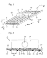
- the ceiling is composed of a plurality of ceiling elements 10, which are arranged in a longitudinal direction x and in a transverse direction y adjacent to each other and ensure a modular design of the ceiling.
- the ceiling elements 10 are each provided with a perforated ceiling plate 11 having an upper side 12, a bottom 13 facing a space to be cooled or heated and a plurality of openings 14 formed by the perforation.
- the openings may be covered for acoustic reasons on the top 12 or the bottom 13 with an air-permeable nonwoven fabric.
- the ceiling plate 11, for example, made of a perforated steel or aluminum sheet is further provided with a beaded side edge 15, which facilitates a Anaptetzen the ceiling elements 10, provided, in particular from Fig. 4 is apparent.
- a heat-transporting medium for example water
- the tubes 20 may also be arranged in a Doppelffleanderform or another form.
- the tubes 20 are mounted on thermally conductive rails 22 which are in heat-conductive contact with the ceiling plate 11.
- the rails 22 are U-shaped in cross-section and have two side walls 23 which extend in the longitudinal direction x.
- the side walls 23 are through a in the transverse direction y extending cross-beam 24 connected to each other.
- the cross-beam is provided with a plurality of projections 25, which make it possible réellestecken the cross-beam 24 on the side walls 23. Due to an equidistant arrangement of the projections 25, the rails 22 and thus the tubes 20 can be arranged on the ceiling plate 11 in a predetermined pattern in which the rails 22 are separated from each other in the transverse direction y by a gap 21.
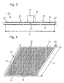
- the air channel 30 is U-shaped in cross-section and has a first leg portion 32, a second leg portion 33 and a base portion 34 interconnecting the first leg portion 32 and the second leg portion 33.
- the side walls representing leg portions 32, 33 adjoin the rails 22 in the transverse direction y.
- the base portion 34 is provided with an opening forming an inlet 31 for the supply air.
- the inlet 31 is connected to a distribution box 36 which extends in the transverse direction y and is provided with a conical end piece which projects into the opening forming the inlet 31.
- the distribution box 36 is provided with a sound-absorbing lining and has a standardized for example DN 80 port 37, through which the supply air is supplied to the distribution box 36 on.
- a perforated baffle 35 is arranged, which extends parallel to the base portion 34.
- the baffle 35 divides the air ducts 30 into an upper area and a lower area and ensures that the supply air supplied from the distribution box 36 to the air ducts 30 is distributed uniformly in the longitudinal direction x.
- the supply air flows from the upper portion through the perforated baffle 35 in the lower region of the air channel 30 and then enters through the one outlet forming openings 14 of the ceiling plate 11 in the below the ceiling plate 11 located space.
- the free cross-sectional area of the ceiling plate 11 is dimensioned so that the openings 14 have a share of the total area of the ceiling panel between 10 percent and 30 percent.
- a specific volume flow between 30 m 3 / h per m 2 and 90 m 3 / h per m 2 ceiling surface can be realized at a relatively low sound pressure level of about 30 db (A).
- the amount of supply air supplied to the room depends primarily on the length I of the air ducts 30 in the longitudinal direction x and the number of air ducts 30.
- the ratio of the width w of the ceiling plate 11 in the longitudinal direction x to the length I of the air ducts 30 in the present case is almost 1: 1, that is, the air ducts 30 extend almost over the entire width w of the ceiling plate 11.
- Is the Length I for example 800 mm, so can be achieved with a total of four air channels 30 and a proportion of the free cross-sectional area of about 16 percent, a flow rate of 90 m 3 / h. If less air is needed, either the number of rails 22 can be reduced or their length can be made shorter.
- the ceiling described above is characterized by a relatively simple assembly and disassembly. This is mainly because the air channels 30 are arranged in the intermediate space 21 between the rails 22 and can be installed in this way independently of the rails 22 and the tubes 20.
- the depending on the temperature of the medium flowing through the tubes 20, both as a cooling ceiling and as an electric blanket usable ceiling has a relatively large active ceiling area, since the openings 14 of the ceiling plate 11 form the outlet for the supply air, so that separate air outlets, which the active ceiling surface and the visual appearance of the ceiling impaired, are unnecessary.
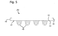
- the baffle plate 35 contributes to the fact that the supply air emerging through the openings 14 over the length 1 of the air channel 30 is evenly distributed and results in a relatively low flow velocity with source air-like flow characteristics, as shown
- Fig. 5 is apparent. To a zug povertybeaten room ventilation also contributes to the parallel arrangement of the air ducts 30, which, in particular the Fig. 4 and 5 to detect, generates a strip-shaped air outlet pattern 16, which ensures a stable flow of air even if the supply air has a lower temperature than the air in the room.
Claims (16)
- Plafond, en particulier plafond réfrigérant ou chauffant, comprenant
une plaque de plafond perforée (11) qui comporte une face supérieure (12), une face inférieure (13) et une pluralité d'ouvertures (14) réparties à des distances régulières sur la surface de base de la plaque de plafond (11) ;
au moins deux tuyaux (20) qui peuvent être parcourus par un milieu transportant de la chaleur et se trouvent sur la face supérieure (12) en contact thermoconducteur avec la plaque de plafond (11), et
au moins un canal à air (30) qui peut être traversé par de l'air frais, et qui comporte une entrée (31) et une sortie formée par les ouvertures (14) ;
dans lequel les tuyaux (20) et le canal à air (30) s'étendent dans une direction longitudinale (x),
dans lequel les tuyaux (20) sont séparés l'un de l'autre par un intervalle (21) dans une direction transversale (y) orthogonale à la direction longitudinale (x), et
dans lequel le canal à air (30) est agencé dans l'intervalle (21) et les ouvertures (14), qui se trouvent dans la région du canal à air (30), forment la sortie. - Plafond selon la revendication 1, caractérisé en ce que le canal à air (30) a une section transversale en forme de U et présente un premier tronçon de branche (32), un second tronçon de branche (33), et un tronçon de base (34) qui relie le premier tronçon de branche (32) et le second tronçon de branche (33) l'un à l'autre.
- Plafond selon la revendication 2, caractérisé en ce qu'une tôle de chicane (35) perforée est agencée dans le canal à air (30), et s'étend de préférence parallèlement au tronçon de base (34).
- Plafond selon la revendication 2 ou 3, caractérisé en ce que le tronçon de base (34) est pourvu d'une ouverture qui forme l'entrée (31) et qui relie le canal à air (30) à un caisson distributeur (36), lequel s'étend de préférence dans la direction transversale (y).
- Plafond selon la revendication 4, caractérisé en ce que le caisson distributeur (36) est pourvu d'une pièce de talon conique, qui est reliée à l'ouverture formant l'entrée (31).
- Plafond selon la revendication 4 ou 5, caractérisé en ce que le caisson distributeur (36) est susceptible d'être doté d'un habillage amortissant les bruits.
- Plafond selon l'une des revendications 1 à 6, caractérisé en ce que la plaque de plafond (11) présente une surface de section transversale libre dont la proportion représente entre 10 % et 30 % de la surface totale de la plaque de plafond (11).
- Plafond selon l'une des revendications 1 à 7, caractérisé en ce que la plaque de plafond (11) possède une largeur (w) dans la direction longitudinale (x), et le canal à air (30) possède une longueur (I), telles que le rapport de la largeur (w) sur la longueur (I) est entre 1,0 et 2,0.
- Plafond selon l'une des revendications 1 à 8, caractérisé en ce que les tuyaux (20) sont fixés sur des rails thermoconducteurs (22).
- Plafond selon la revendication 9, caractérisé en ce que les rails (22) sont pourvus d'au moins une paroi latérale (23) qui s'étend dans la direction longitudinale (x) et qui est adjacente au canal à air (30) dans la direction transversale (y).
- Plafond selon la revendication 9 ou 10, caractérisé en ce que les rails (22) sont reliés les uns aux autres par au moins une traverse (24) qui s'étend dans la direction transversale (y).
- Plafond selon l'une des revendications 1 à 11, caractérisé par une pluralité de tuyaux (20), qui sont agencés sous forme de méandres sur la face supérieure (12) de la plaque de plafond (11).
- Plafond selon l'une des revendications 1 à 12, caractérisé en ce que la plaque de plafond (11) est en tôle d'acier ou d'aluminium, en plâtre doublé de carton, ou en un matériau composite.
- Plafond selon l'une des revendications 1 à 13, caractérisé en ce que les ouvertures (14) sur la face supérieure (12) et/ou sur la face inférieure (13) de la plaque de plafond (11) sont recouvertes d'une nappe de fibres perméable à l'air.
- Plafond selon l'une des revendications 1 à 14, caractérisé par des ouvertures (14) du même type, qui ont de préférence la forme de trous arrondis, de trous carrés, de trous triangulaires, de trous en losanges ou de trous oblongs.
- Plafond selon l'une des revendications 1 à 15, caractérisé par une pluralité d'éléments de plafond (10) qui sont agencés adjacents les uns aux autres dans la direction transversale (y) et/ou dans la direction longitudinale (x).
Applications Claiming Priority (2)
| Application Number | Priority Date | Filing Date | Title |
|---|---|---|---|
| DE102004018278 | 2004-04-13 | ||
| DE102004018278A DE102004018278B4 (de) | 2004-04-13 | 2004-04-13 | Decke, insbesondere Kühl-oder Heizdecke |
Publications (3)
| Publication Number | Publication Date |
|---|---|
| EP1586823A2 EP1586823A2 (fr) | 2005-10-19 |
| EP1586823A3 EP1586823A3 (fr) | 2006-05-24 |
| EP1586823B1 true EP1586823B1 (fr) | 2010-03-31 |
Family
ID=33483240
Family Applications (1)
| Application Number | Title | Priority Date | Filing Date |
|---|---|---|---|
| EP05008074A Active EP1586823B1 (fr) | 2004-04-13 | 2005-04-13 | Plafond, en particulier plafond réfrigérant ou chauffant |
Country Status (4)
| Country | Link |
|---|---|
| EP (1) | EP1586823B1 (fr) |
| AT (1) | ATE462937T1 (fr) |
| CH (1) | CH694403A5 (fr) |
| DE (2) | DE102004018278B4 (fr) |
Cited By (3)
| Publication number | Priority date | Publication date | Assignee | Title |
|---|---|---|---|---|
| WO2011152786A1 (fr) * | 2010-05-31 | 2011-12-08 | Suncore Ab | Agencement et système pour le conditionnement d'air |
| DE202017100665U1 (de) | 2017-02-08 | 2017-10-23 | Uponor Innovation Ab | Deckenelement, insbesondere einer Kühl- oder Heizdecke |
| DE102020121124A1 (de) | 2020-08-11 | 2022-02-17 | As Led Lighting Gmbh | Deckenelement mit integrierter Beleuchtung |
Families Citing this family (9)
| Publication number | Priority date | Publication date | Assignee | Title |
|---|---|---|---|---|
| DE102004018278B4 (de) * | 2004-04-13 | 2006-01-19 | Thermosoft Klimatechnik Gmbh | Decke, insbesondere Kühl-oder Heizdecke |
| DE202009000717U1 (de) | 2009-01-21 | 2009-04-02 | Thermolution GmbH Kühldeckensysteme | Decken- oder Wandwärmetauscherelement |
| DE102011121164B4 (de) | 2011-12-16 | 2014-08-21 | Frenger Systemen BV Heiz- und Kühltechnik GmbH | Strahlflächenaufbau mit Absorptionsbox |
| CH707246A1 (de) * | 2012-11-29 | 2014-05-30 | Barcol Air | Deckenelement für eine Heiz- und Kühldecke sowie Heiz- und Kühldecke. |
| MX2019002951A (es) | 2016-09-15 | 2019-09-11 | Armstrong World Ind Inc | Sistema de techo con movimiento aereo. |
| CH713050B1 (de) | 2016-10-17 | 2019-01-31 | Barcol Air Group Ag | Deckenelement sowie Heiz- und Kühldecke. |
| DE202017103113U1 (de) * | 2017-05-23 | 2017-07-31 | Erwin Müller GmbH | Decken-Klimatisierungsvorrichtung mit Tragkonstruktion |
| CN109059081B (zh) * | 2018-06-25 | 2020-11-27 | 中国矿业大学 | 一种吊顶式室内供暖装置 |
| CH718960A2 (de) * | 2021-09-15 | 2023-03-15 | Zehnder Group Int Ag | Deckenelement für eine Kühl- und/oder Heizdecke, umfassend einen Luftauslasskasten. |
Family Cites Families (8)
| Publication number | Priority date | Publication date | Assignee | Title |
|---|---|---|---|---|
| CH287801A (de) * | 1944-12-18 | 1952-12-31 | Frenger Gunnar | Strahlungs-Heiz- oder -Kühleinrichtung für Räume. |
| SE459447B (sv) * | 1987-06-17 | 1989-07-03 | Stefan Jacek Moszkowski | Saett och anordning foer att ventilera ett rum genom inblaasning av luft horisontellt under en vaermevaexlande takmonterad panel |
| DE4201595C2 (de) * | 1992-01-22 | 1995-03-09 | Schmidt Reuter | Raumkühldecke |
| DE4210279A1 (de) * | 1992-03-28 | 1993-09-30 | Turbon Tunzini Klimatechnik | Quelluftdurchlaß für raumlufttechnische Anlagen |
| DE29622052U1 (de) * | 1996-12-19 | 1998-01-22 | Kessler & Luch Gmbh | Deckenkühlmodul |
| DE10043968A1 (de) * | 2000-09-06 | 2002-04-04 | Wilhelmi Werke Ag | Verfahren zum Klimatisieren von Räumen und Klimadecke |
| DE10219669A1 (de) * | 2002-05-02 | 2004-02-19 | Valentin Rosel | Kühl-Heiz-Lüftungsmodul |
| DE102004018278B4 (de) * | 2004-04-13 | 2006-01-19 | Thermosoft Klimatechnik Gmbh | Decke, insbesondere Kühl-oder Heizdecke |
-
2004
- 2004-04-13 DE DE102004018278A patent/DE102004018278B4/de not_active Expired - Fee Related
- 2004-05-21 CH CH00880/04A patent/CH694403A5/de not_active IP Right Cessation
-
2005
- 2005-04-13 DE DE502005009298T patent/DE502005009298D1/de active Active
- 2005-04-13 EP EP05008074A patent/EP1586823B1/fr active Active
- 2005-04-13 AT AT05008074T patent/ATE462937T1/de active
Cited By (3)
| Publication number | Priority date | Publication date | Assignee | Title |
|---|---|---|---|---|
| WO2011152786A1 (fr) * | 2010-05-31 | 2011-12-08 | Suncore Ab | Agencement et système pour le conditionnement d'air |
| DE202017100665U1 (de) | 2017-02-08 | 2017-10-23 | Uponor Innovation Ab | Deckenelement, insbesondere einer Kühl- oder Heizdecke |
| DE102020121124A1 (de) | 2020-08-11 | 2022-02-17 | As Led Lighting Gmbh | Deckenelement mit integrierter Beleuchtung |
Also Published As
| Publication number | Publication date |
|---|---|
| DE502005009298D1 (de) | 2010-05-12 |
| EP1586823A2 (fr) | 2005-10-19 |
| ATE462937T1 (de) | 2010-04-15 |
| EP1586823A3 (fr) | 2006-05-24 |
| DE102004018278A1 (de) | 2005-11-17 |
| DE102004018278B4 (de) | 2006-01-19 |
| CH694403A5 (de) | 2004-12-31 |
Similar Documents
| Publication | Publication Date | Title |
|---|---|---|
| EP1586823B1 (fr) | Plafond, en particulier plafond réfrigérant ou chauffant | |
| EP0497296A2 (fr) | Installation de filtre-ventilateur pour l'utilisation dans des salles blanches | |
| EP2366082B1 (fr) | Bouche d'aération dotée d'un boîtier et plafond flottant doté d'une bouche d'aération | |
| DE102010044590A1 (de) | Anordnung zur Belüftung eines Raums, insbesondere eines Laborraums | |
| EP1411303B1 (fr) | Elément de régulation de la température d'une enceinte et son agencement | |
| EP2210992A2 (fr) | Plaque semi-finie thermoactive dotée d'un absorbeur acoustique | |
| EP3285017B1 (fr) | Panneau de plafond radiant chauffant et rafraîchissant comprenant au moins un ventilateur | |
| EP0563509B1 (fr) | Sortie d'air pour installation de traitement d'air | |
| DE2328186C2 (de) | Induktionsgerät | |
| EP3236173B1 (fr) | Procédé de climatisation d'une pièce | |
| EP3499145A1 (fr) | Dispositif de mise en température d'un espace | |
| DE10150989C1 (de) | Flächiges Decken- oder Wandelement und mobile Stellwand mit einem solchen Element | |
| DE19822806A1 (de) | Stallbelüftungsanlage | |
| EP3477212B1 (fr) | Dispositif de distribution d'air ainsi que procédé d'aération d'une pièce | |
| EP1162411B1 (fr) | Appareil de ventilation/climatisation | |
| EP3702684A1 (fr) | Climatisation des pièces comprenant une amenée d'air frais et thermorégulation | |
| EP0893655B1 (fr) | Unité de chauffage pour chauffage à air chaud pour églises | |
| EP1888992B1 (fr) | Radiateur | |
| DE4308969C1 (de) | Kühldecke | |
| DE19738172C1 (de) | Einrichtung zum Temperieren von Gebäuden | |
| CH707246A1 (de) | Deckenelement für eine Heiz- und Kühldecke sowie Heiz- und Kühldecke. | |
| DE2442378A1 (de) | Klimaanlage | |
| DE10212811C1 (de) | Schallabsorber | |
| DE102004001765A1 (de) | Luftschleieranlage | |
| EP1072846A2 (fr) | Convecteur pour plafond |
Legal Events
| Date | Code | Title | Description |
|---|---|---|---|
| PUAI | Public reference made under article 153(3) epc to a published international application that has entered the european phase |
Free format text: ORIGINAL CODE: 0009012 |
|
| AK | Designated contracting states |
Kind code of ref document: A2 Designated state(s): AT BE BG CH CY CZ DE DK EE ES FI FR GB GR HU IE IS IT LI LT LU MC NL PL PT RO SE SI SK TR |
|
| AX | Request for extension of the european patent |
Extension state: AL BA HR LV MK YU |
|
| PUAL | Search report despatched |
Free format text: ORIGINAL CODE: 0009013 |
|
| AK | Designated contracting states |
Kind code of ref document: A3 Designated state(s): AT BE BG CH CY CZ DE DK EE ES FI FR GB GR HU IE IS IT LI LT LU MC NL PL PT RO SE SI SK TR |
|
| AX | Request for extension of the european patent |
Extension state: AL BA HR LV MK YU |
|
| 17P | Request for examination filed |
Effective date: 20060529 |
|
| RAP1 | Party data changed (applicant data changed or rights of an application transferred) |
Owner name: ZENT-FRENGER HOLDING GMBH |
|
| AKX | Designation fees paid |
Designated state(s): AT CH DE IT LI |
|
| 17Q | First examination report despatched |
Effective date: 20070621 |
|
| GRAP | Despatch of communication of intention to grant a patent |
Free format text: ORIGINAL CODE: EPIDOSNIGR1 |
|
| GRAS | Grant fee paid |
Free format text: ORIGINAL CODE: EPIDOSNIGR3 |
|
| GRAA | (expected) grant |
Free format text: ORIGINAL CODE: 0009210 |
|
| AK | Designated contracting states |
Kind code of ref document: B1 Designated state(s): AT CH DE IT LI |
|
| REG | Reference to a national code |
Ref country code: CH Ref legal event code: EP |
|
| REF | Corresponds to: |
Ref document number: 502005009298 Country of ref document: DE Date of ref document: 20100512 Kind code of ref document: P |
|
| REG | Reference to a national code |
Ref country code: CH Ref legal event code: NV Representative=s name: BOHEST AG |
|
| PLBE | No opposition filed within time limit |
Free format text: ORIGINAL CODE: 0009261 |
|
| STAA | Information on the status of an ep patent application or granted ep patent |
Free format text: STATUS: NO OPPOSITION FILED WITHIN TIME LIMIT |
|
| 26N | No opposition filed |
Effective date: 20110104 |
|
| REG | Reference to a national code |
Ref country code: DE Ref legal event code: R081 Ref document number: 502005009298 Country of ref document: DE Owner name: UPONOR INNOVATION AB, SE Free format text: FORMER OWNER: ZENT-FRENGER HOLDING GMBH, 64646 HEPPENHEIM, DE Effective date: 20110824 Ref country code: DE Ref legal event code: R082 Ref document number: 502005009298 Country of ref document: DE Representative=s name: EPPING HERMANN FISCHER, PATENTANWALTSGESELLSCH, DE Effective date: 20110824 Ref country code: DE Ref legal event code: R082 Ref document number: 502005009298 Country of ref document: DE Representative=s name: EPPING HERMANN FISCHER PATENTANWALTSGESELLSCHA, DE Effective date: 20110824 |
|
| REG | Reference to a national code |
Ref country code: CH Ref legal event code: PUE Owner name: UPONOR INNOVATION AB Free format text: ZENT-FRENGER HOLDING GMBH#SCHWARZWALDSTRASSE 2#64646 HEPPENHEIM (DE) -TRANSFER TO- UPONOR INNOVATION AB#C/O UPONOR AB PO BOX 101#730 61 VIRSBO (SE) |
|
| REG | Reference to a national code |
Ref country code: AT Ref legal event code: PC Ref document number: 462937 Country of ref document: AT Kind code of ref document: T Owner name: UPONOR INNOVATION AB, SE Effective date: 20111213 |
|
| REG | Reference to a national code |
Ref country code: CH Ref legal event code: PCAR Free format text: NEW ADDRESS: HOLBEINSTRASSE 36-38, 4051 BASEL (CH) |
|
| REG | Reference to a national code |
Ref country code: DE Ref legal event code: R081 Ref document number: 502005009298 Country of ref document: DE Owner name: ZENT-FRENGER GMBH, DE Free format text: FORMER OWNER: UPONOR INNOVATION AB, FRISTAD, SE Ref country code: DE Ref legal event code: R082 Ref document number: 502005009298 Country of ref document: DE Representative=s name: FLUEGEL PREISSNER SCHOBER SEIDEL PATENTANWAELT, DE |
|
| REG | Reference to a national code |
Ref country code: AT Ref legal event code: PC Ref document number: 462937 Country of ref document: AT Kind code of ref document: T Owner name: ZENT-FRENGER GMBH, DE Effective date: 20190110 |
|
| REG | Reference to a national code |
Ref country code: CH Ref legal event code: PUE Owner name: ZENT-FRENGER GMBH, DE Free format text: FORMER OWNER: UPONOR INNOVATION AB, SE |
|
| PGFP | Annual fee paid to national office [announced via postgrant information from national office to epo] |
Ref country code: IT Payment date: 20220429 Year of fee payment: 18 |
|
| PGFP | Annual fee paid to national office [announced via postgrant information from national office to epo] |
Ref country code: CH Payment date: 20220421 Year of fee payment: 18 Ref country code: AT Payment date: 20220414 Year of fee payment: 18 |
|
| PGFP | Annual fee paid to national office [announced via postgrant information from national office to epo] |
Ref country code: DE Payment date: 20230503 Year of fee payment: 19 |
|
| REG | Reference to a national code |
Ref country code: CH Ref legal event code: PL |
|
| REG | Reference to a national code |
Ref country code: AT Ref legal event code: MM01 Ref document number: 462937 Country of ref document: AT Kind code of ref document: T Effective date: 20230413 |
|
| PG25 | Lapsed in a contracting state [announced via postgrant information from national office to epo] |
Ref country code: LI Free format text: LAPSE BECAUSE OF NON-PAYMENT OF DUE FEES Effective date: 20230430 Ref country code: CH Free format text: LAPSE BECAUSE OF NON-PAYMENT OF DUE FEES Effective date: 20230430 Ref country code: AT Free format text: LAPSE BECAUSE OF NON-PAYMENT OF DUE FEES Effective date: 20230413 |