EP1586804A2 - Système de distribution de liquide hydraulique - Google Patents
Système de distribution de liquide hydraulique Download PDFInfo
- Publication number
- EP1586804A2 EP1586804A2 EP05005681A EP05005681A EP1586804A2 EP 1586804 A2 EP1586804 A2 EP 1586804A2 EP 05005681 A EP05005681 A EP 05005681A EP 05005681 A EP05005681 A EP 05005681A EP 1586804 A2 EP1586804 A2 EP 1586804A2
- Authority
- EP
- European Patent Office
- Prior art keywords
- supply system
- hydraulic supply
- air
- separation chamber
- gas
- Prior art date
- Legal status (The legal status is an assumption and is not a legal conclusion. Google has not performed a legal analysis and makes no representation as to the accuracy of the status listed.)
- Withdrawn
Links
- 239000012530 fluid Substances 0.000 claims abstract description 19
- 238000000926 separation method Methods 0.000 claims description 36
- 230000000712 assembly Effects 0.000 claims description 7
- 238000000429 assembly Methods 0.000 claims description 7
- 238000002485 combustion reaction Methods 0.000 claims description 7
- 239000007789 gas Substances 0.000 description 31
- 239000000443 aerosol Substances 0.000 description 1
- 239000000567 combustion gas Substances 0.000 description 1
- 230000001934 delay Effects 0.000 description 1
- 230000000694 effects Effects 0.000 description 1
- 230000005484 gravity Effects 0.000 description 1
- 230000001771 impaired effect Effects 0.000 description 1
- 239000007788 liquid Substances 0.000 description 1
- 230000001050 lubricating effect Effects 0.000 description 1
- 238000005461 lubrication Methods 0.000 description 1
- 239000007787 solid Substances 0.000 description 1
- 239000000126 substance Substances 0.000 description 1
- 238000013022 venting Methods 0.000 description 1
Images
Classifications
-
- F—MECHANICAL ENGINEERING; LIGHTING; HEATING; WEAPONS; BLASTING
- F16—ENGINEERING ELEMENTS AND UNITS; GENERAL MEASURES FOR PRODUCING AND MAINTAINING EFFECTIVE FUNCTIONING OF MACHINES OR INSTALLATIONS; THERMAL INSULATION IN GENERAL
- F16N—LUBRICATING
- F16N39/00—Arrangements for conditioning of lubricants in the lubricating system
- F16N39/002—Arrangements for conditioning of lubricants in the lubricating system by deaeration
Definitions
- Hydraulic supply system of machines in particular of internal combustion engines, with a pump, which from a reservoir hydraulic fluid through cables to various functional assemblies, such as bearings, Switching or control elements, actuators or the like promotes, from where the Hydraulic fluid passes back to the storage room.
- the DE-42 14 324 C2 and also DE-199 48 163 A1 describe devices for Separation of oily aerosols and return of the oil content in the Engine housing of internal combustion engines. This is however means for venting the engine casing of internal combustion engines, in which the by moving between them against each other Components escaping combustion gases oily or solid substances entrain, which should then be eliminated from the gases.
- Such Facilities are designed in their function to the main component air / gas and not on the separation of lower air / gas components a hydraulic fluid. Therefore, they are for use in hydraulic supply systems not suitable.
- the object of the invention is therefore a hydraulic supply system so to improve that the function of all assemblies, such as bearings, switching or Controls, actuators and the like, fully preserved and not is affected by excessive air or gas
- the object of the invention is achieved in that in the region of the lines the hydraulic supply system, an air / gas separator is provided. This ensures that the air / gas content in the hydraulic fluid does not rise so much that the functioning of the assemblies is impaired. At first it does not matter how the separation device works is designed, but that a hydraulic supply system is equipped in an inventive manner with a separator.
- the air / gas separator a rotationally symmetrical separation chamber, the one tangentially to the separation chamber connected inflow line and a preferably also has tangentially connected discharge line.
- the air / gas separator is based, as is known in principle, on the System of centrifugal separation, wherein during the rotation of the hydraulic fluid in the rotationally symmetrical separation space the heavy components, So the liquid itself, attached to the wall and the air / gas components to gather in the center of the separation room.
- the rotation axis of the separation chamber is arranged substantially vertically in the machine and the discharge line is far below the inflow line connected.
- the air / gas content is not only in the middle of the rotationally symmetric separation chamber, but also Due to gravity migrate into the upper part of the separation chamber, so that only hydraulic fluid reaches the discharge line, which has a low proportion of air / gas having.
- the inflow line is in the upper half of the separation chamber arranged while the discharge line in the lower third of the Abscheid Vogelmes is arranged.
- the discharge line can in the same direction to a through the through the inflow line incoming hydraulic fluid generated swirl flow arranged be, or in opposite directions. Is she in the same direction, so towards the Arranged swirl flow, so there is no obstruction of the flow. It is however, in this case possible that a lower separation of air / gas shares takes place because air / gas components can be carried along. In an opposite orientation of the discharge line is the probability that air / gas components are entrained, low.
- an air / gas separation channel is connected, whose cross-section is throttled.
- the Throttling is advantageous so that the pressure of the hydraulic fluid is not unintentional drops and the functional assemblies insufficient with hydraulic fluid be supplied.
- the throttle cross section may be formed either as a nozzle or
- the separation channel can be divided into a gap cross-section, e.g. a warehouse, preferably of a camshaft bearing, open.
- a camshaft bearing is therefore recommended, because in modern internal combustion engines in the area of the cylinder head, So at a geodetically high point of the hydraulic supply system the camshaft is supported and because in the area of the camshaft bearings, e.g. in the region of the bearing block, the inventive air / gas separator can be installed.
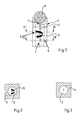
- FIG. 1 a Air / gas separator called a rotationally symmetric, designated 2 formed in the embodiment circular cylindrical Having the separation chamber, to the one, shown in detail in Figure 2 inflow 3 and a designated 4, shown in detail in Figure 3 Outflow line are connected tangentially.
- the axis of rotation of the separation chamber 2 is vertically aligned within an internal combustion engine, the inflow line 3 in the upper half and the outflow line 4 in the lower third of the separation chamber 2 are connected.
- the through the tangential Inflow of hydraulic fluid generated by the inflow 3 Swirl flow is indicated by a bold arrow in FIG. 1.
- the discharge line 4 is opposite to the direction of the swirl flow connected according to arrow 5, so that the probability is very low is that air / gas shares due to the swirl flow in the discharge line 4 be carried away.
Landscapes
- Engineering & Computer Science (AREA)
- General Engineering & Computer Science (AREA)
- Mechanical Engineering (AREA)
- Lubrication Details And Ventilation Of Internal Combustion Engines (AREA)
- Fluid-Pressure Circuits (AREA)
- Separating Particles In Gases By Inertia (AREA)
Applications Claiming Priority (2)
| Application Number | Priority Date | Filing Date | Title |
|---|---|---|---|
| DE102004018389 | 2004-04-16 | ||
| DE200410018389 DE102004018389A1 (de) | 2004-04-16 | 2004-04-16 | Hydraulisches Versorgungssystem von Maschinen |
Publications (2)
| Publication Number | Publication Date |
|---|---|
| EP1586804A2 true EP1586804A2 (fr) | 2005-10-19 |
| EP1586804A3 EP1586804A3 (fr) | 2010-03-24 |
Family
ID=34934295
Family Applications (1)
| Application Number | Title | Priority Date | Filing Date |
|---|---|---|---|
| EP05005681A Withdrawn EP1586804A3 (fr) | 2004-04-16 | 2005-03-16 | Système de distribution de liquide hydraulique |
Country Status (2)
| Country | Link |
|---|---|
| EP (1) | EP1586804A3 (fr) |
| DE (1) | DE102004018389A1 (fr) |
Citations (2)
| Publication number | Priority date | Publication date | Assignee | Title |
|---|---|---|---|---|
| DE4214324A1 (de) | 1992-04-30 | 1993-11-04 | Knecht Filterwerke Gmbh | Vorrichtung zur abscheidung von oelhaltigen aerosolen |
| DE19948163A1 (de) | 1999-10-07 | 2001-04-12 | Volkswagen Ag | Vorrichtung für die Kurbelgehäuse/Zylinderkopf-Entlüftung eines Verbrennungsmotors |
Family Cites Families (14)
| Publication number | Priority date | Publication date | Assignee | Title |
|---|---|---|---|---|
| GB1284933A (en) * | 1969-06-19 | 1972-08-09 | Brown Tractors Ltd | Bleeding hydraulic systems |
| FR2342420A1 (fr) * | 1976-02-25 | 1977-09-23 | Wabco Westinghouse | Dispositif de purge automatique et d'alimentation pour circuit hydraulique |
| GB2040739B (en) * | 1979-02-01 | 1982-11-17 | Technical Dev Co | Apparatus for removing entrapped gas and separating out particles from fluid |
| DE3623238A1 (de) * | 1986-07-10 | 1988-02-04 | Bayerische Motoren Werke Ag | Vorrichtung zur bereitstellung von im wesentlichen luftfreiem schmieroel |
| JPH0267015U (fr) * | 1988-11-10 | 1990-05-21 | ||
| DE4326580A1 (de) * | 1993-08-07 | 1995-02-09 | Audi Ag | Vorrichtung zum Entgasen eines hydraulischen Systems |
| JPH08229309A (ja) * | 1995-02-27 | 1996-09-10 | Ishikawajima Harima Heavy Ind Co Ltd | 多量の気泡を含む潤滑油の油と空気の分離装置 |
| JP3578529B2 (ja) * | 1995-08-28 | 2004-10-20 | 新キャタピラー三菱株式会社 | 建設機械の油圧回路における作動油気泡除去装置 |
| JPH09303329A (ja) * | 1996-05-08 | 1997-11-25 | Hitachi Building Syst Co Ltd | 油中の気泡分離装置 |
| DE19717043C2 (de) * | 1997-04-23 | 2003-05-22 | Daimler Chrysler Ag | Verfahren zum Entwässern und/oder Entgasen von Hydraulikflüssigkeiten, Vorrichtung zur Durchführung des Verfahrens und Verwendung der Vorrichtung |
| DE19756018A1 (de) * | 1997-12-17 | 1999-06-24 | Porsche Ag | Einrichtung zur Druck- und/oder Schmiermittelbeaufschlagung eines hydraulischen Verbrauchers in einer Brennkraftmaschine |
| US6318234B1 (en) * | 2000-06-30 | 2001-11-20 | Caterpillar Inc. | Line vent arrangement for electro-hydraulic circuit |
| EP1297875A1 (fr) * | 2001-09-27 | 2003-04-02 | Techspace Aero S.A. | Desaerateur statique a niveau constant |
| JP4128085B2 (ja) * | 2002-05-22 | 2008-07-30 | 株式会社小松製作所 | 液体タンク |
-
2004
- 2004-04-16 DE DE200410018389 patent/DE102004018389A1/de not_active Withdrawn
-
2005
- 2005-03-16 EP EP05005681A patent/EP1586804A3/fr not_active Withdrawn
Patent Citations (2)
| Publication number | Priority date | Publication date | Assignee | Title |
|---|---|---|---|---|
| DE4214324A1 (de) | 1992-04-30 | 1993-11-04 | Knecht Filterwerke Gmbh | Vorrichtung zur abscheidung von oelhaltigen aerosolen |
| DE19948163A1 (de) | 1999-10-07 | 2001-04-12 | Volkswagen Ag | Vorrichtung für die Kurbelgehäuse/Zylinderkopf-Entlüftung eines Verbrennungsmotors |
Also Published As
| Publication number | Publication date |
|---|---|
| DE102004018389A1 (de) | 2005-11-03 |
| EP1586804A3 (fr) | 2010-03-24 |
Similar Documents
| Publication | Publication Date | Title |
|---|---|---|
| EP1644124B1 (fr) | Dispositif pour ouvrir ou fermer des cyclones | |
| DE102013104051B4 (de) | Zentralventil für einen Schwenkmotorversteller | |
| EP2635791B1 (fr) | Système d'injection de carburant d'un moteur à combustion interne | |
| DE112007001867T5 (de) | Kraftstoffanlage mit Entlüftung und Rücklaufsperre | |
| DE2605175C3 (de) | Öldrucksteuerventil für Einleitungs-ölschmieranlagen | |
| DE102013104031B4 (de) | Zentralventil für einen Schwenkmotorversteller | |
| WO2006002800A1 (fr) | Dispositif pour separer de l'eau et pour extraire des impuretes par filtration | |
| DE3040478A1 (de) | Ventilanordnung fuer eine entlueftungsleitung | |
| DE10247665B4 (de) | Regelvorrichtung und Ventilblock für eine Regelvorrichtung | |
| DE102013203054B4 (de) | Ruhezonenfluidfilter, Fluidventil mit integriertem Fluidfilter und Fluidströmungssteuerventil mit integriertem Fluidfilter | |
| DE1600180B2 (de) | Antriebsuebertragungsvorrichtung mit schlupfkupplung und regelventil | |
| CH645435A5 (de) | Kolbenpumpe. | |
| EP0051728B1 (fr) | Dispositif de commande pour un vérin hydraulique | |
| DE3404982C2 (fr) | ||
| EP1586804A2 (fr) | Système de distribution de liquide hydraulique | |
| DE102017120139A1 (de) | Ölnebelabscheider mit Druckbegrenzungsventilen | |
| EP2493589B1 (fr) | Filtre retour/aspiration doté d'une soupape à double fonction | |
| DE102016114263A1 (de) | Partikelseparator | |
| DE2504562A1 (de) | Axialkolben-druckfluessigkeitspumpe | |
| DE3107012A1 (de) | Schieberventil fuer oel-in-wasser-emulsionen | |
| EP1999344B1 (fr) | Dispositif de separation de particules fluides dans un ecoulement de gaz qui sort d'un carter de vilebrequin | |
| EP0943057A1 (fr) | Distributeur pour la commande, independante de la charge, d'un consommateur hydraulique au niveau du sens et de la vitesse | |
| DE60314310T2 (de) | Zentrifuge und Verfahren zum Entleeren einer Zentrifuge | |
| DE102011075620B4 (de) | Verdrängerpumpe mit einem Bypassventil | |
| DE3420194A1 (de) | Regelventil zur druck- oder stromregelung |
Legal Events
| Date | Code | Title | Description |
|---|---|---|---|
| PUAI | Public reference made under article 153(3) epc to a published international application that has entered the european phase |
Free format text: ORIGINAL CODE: 0009012 |
|
| 17P | Request for examination filed |
Effective date: 20050316 |
|
| AK | Designated contracting states |
Kind code of ref document: A2 Designated state(s): AT BE BG CH CY CZ DE DK EE ES FI FR GB GR HU IE IS IT LI LT LU MC NL PL PT RO SE SI SK TR |
|
| AX | Request for extension of the european patent |
Extension state: AL BA HR LV MK YU |
|
| RAP1 | Party data changed (applicant data changed or rights of an application transferred) |
Owner name: SCHAEFFLER KG |
|
| PUAL | Search report despatched |
Free format text: ORIGINAL CODE: 0009013 |
|
| AK | Designated contracting states |
Kind code of ref document: A3 Designated state(s): AT BE BG CH CY CZ DE DK EE ES FI FR GB GR HU IE IS IT LI LT LU MC NL PL PT RO SE SI SK TR |
|
| AX | Request for extension of the european patent |
Extension state: AL BA HR LV MK YU |
|
| AKX | Designation fees paid |
Designated state(s): DE FR IT SE |
|
| STAA | Information on the status of an ep patent application or granted ep patent |
Free format text: STATUS: THE APPLICATION IS DEEMED TO BE WITHDRAWN |
|
| 18D | Application deemed to be withdrawn |
Effective date: 20100925 |
|
| P01 | Opt-out of the competence of the unified patent court (upc) registered |
Effective date: 20230522 |