EP1586767A2 - Démarrage et freinage commandés pour moteur à combustion interne - Google Patents
Démarrage et freinage commandés pour moteur à combustion interne Download PDFInfo
- Publication number
- EP1586767A2 EP1586767A2 EP05100930A EP05100930A EP1586767A2 EP 1586767 A2 EP1586767 A2 EP 1586767A2 EP 05100930 A EP05100930 A EP 05100930A EP 05100930 A EP05100930 A EP 05100930A EP 1586767 A2 EP1586767 A2 EP 1586767A2
- Authority
- EP
- European Patent Office
- Prior art keywords
- engine
- speed
- cylinder
- stroke
- cylinders
- Prior art date
- Legal status (The legal status is an assumption and is not a legal conclusion. Google has not performed a legal analysis and makes no representation as to the accuracy of the status listed.)
- Withdrawn
Links
Images


Classifications
-
- F—MECHANICAL ENGINEERING; LIGHTING; HEATING; WEAPONS; BLASTING
- F02—COMBUSTION ENGINES; HOT-GAS OR COMBUSTION-PRODUCT ENGINE PLANTS
- F02D—CONTROLLING COMBUSTION ENGINES
- F02D41/00—Electrical control of supply of combustible mixture or its constituents
- F02D41/009—Electrical control of supply of combustible mixture or its constituents using means for generating position or synchronisation signals
-
- F—MECHANICAL ENGINEERING; LIGHTING; HEATING; WEAPONS; BLASTING
- F02—COMBUSTION ENGINES; HOT-GAS OR COMBUSTION-PRODUCT ENGINE PLANTS
- F02D—CONTROLLING COMBUSTION ENGINES
- F02D41/00—Electrical control of supply of combustible mixture or its constituents
- F02D41/02—Circuit arrangements for generating control signals
- F02D41/04—Introducing corrections for particular operating conditions
- F02D41/042—Introducing corrections for particular operating conditions for stopping the engine
-
- F—MECHANICAL ENGINEERING; LIGHTING; HEATING; WEAPONS; BLASTING
- F02—COMBUSTION ENGINES; HOT-GAS OR COMBUSTION-PRODUCT ENGINE PLANTS
- F02D—CONTROLLING COMBUSTION ENGINES
- F02D41/00—Electrical control of supply of combustible mixture or its constituents
- F02D41/02—Circuit arrangements for generating control signals
- F02D41/04—Introducing corrections for particular operating conditions
- F02D41/06—Introducing corrections for particular operating conditions for engine starting or warming up
- F02D41/062—Introducing corrections for particular operating conditions for engine starting or warming up for starting
- F02D41/064—Introducing corrections for particular operating conditions for engine starting or warming up for starting at cold start
-
- F—MECHANICAL ENGINEERING; LIGHTING; HEATING; WEAPONS; BLASTING
- F02—COMBUSTION ENGINES; HOT-GAS OR COMBUSTION-PRODUCT ENGINE PLANTS
- F02D—CONTROLLING COMBUSTION ENGINES
- F02D41/00—Electrical control of supply of combustible mixture or its constituents
- F02D41/30—Controlling fuel injection
- F02D41/3011—Controlling fuel injection according to or using specific or several modes of combustion
- F02D41/3017—Controlling fuel injection according to or using specific or several modes of combustion characterised by the mode(s) being used
- F02D41/3058—Controlling fuel injection according to or using specific or several modes of combustion characterised by the mode(s) being used the engine working with a variable number of cycles
-
- F—MECHANICAL ENGINEERING; LIGHTING; HEATING; WEAPONS; BLASTING
- F02—COMBUSTION ENGINES; HOT-GAS OR COMBUSTION-PRODUCT ENGINE PLANTS
- F02N—STARTING OF COMBUSTION ENGINES; STARTING AIDS FOR SUCH ENGINES, NOT OTHERWISE PROVIDED FOR
- F02N99/00—Subject matter not provided for in other groups of this subclass
- F02N99/002—Starting combustion engines by ignition means
- F02N99/006—Providing a combustible mixture inside the cylinder
-
- F—MECHANICAL ENGINEERING; LIGHTING; HEATING; WEAPONS; BLASTING
- F02—COMBUSTION ENGINES; HOT-GAS OR COMBUSTION-PRODUCT ENGINE PLANTS
- F02D—CONTROLLING COMBUSTION ENGINES
- F02D41/00—Electrical control of supply of combustible mixture or its constituents
- F02D41/0002—Controlling intake air
- F02D2041/001—Controlling intake air for engines with variable valve actuation
-
- F—MECHANICAL ENGINEERING; LIGHTING; HEATING; WEAPONS; BLASTING
- F02—COMBUSTION ENGINES; HOT-GAS OR COMBUSTION-PRODUCT ENGINE PLANTS
- F02D—CONTROLLING COMBUSTION ENGINES
- F02D41/00—Electrical control of supply of combustible mixture or its constituents
- F02D41/009—Electrical control of supply of combustible mixture or its constituents using means for generating position or synchronisation signals
- F02D2041/0095—Synchronisation of the cylinders during engine shutdown
Definitions
- This disclosure relates to internal combustion engines, and more particularly to starting and stopping such engines.
- a separate auxiliary device such as a starter motor and large battery are often provided in order to start the engine.
- the starter motor draws power from the battery in order to turn a flywheel, which, in turn, rotates the engine's crankshaft.
- a starter motor In a four-stroke engine, a starter motor must provide sufficient power to rotate the crankshaft enough to complete a compression stroke. Once a compression stroke is completed, the engine fires the compressed charge and thus begins normal engine operation.
- the invention features a method of starting an internal combustion engine that includes selecting a cylinder for initial firing based upon the piston of the cylinder being located in a predetermined position along its stroke, injecting fuel into the selected cylinder to create an uncompressed fuel-air mixture, and igniting the uncompressed fuel-air mixture in the selected cylinder.
- Cylinders are subsequently selected for firing as a function of cylind er piston position without regard to normal firing order, injected with fuel to create an uncompressed fuel -air mixture and fired until at least there is sufficient kinetic energy to complete a compression stroke in at least one of the cylinders.
- cylinders are fired according to the predefined normal firing order.
- Various embodiments may include one or more of the following features.
- the method may also, prior to firing the cylinders according to their normal f iring order, adjust a dynamic compression ratio of a selected cylinder by adjusting valve event parameters (e.g., valve lift and timing) of the cylinder.
- valve event parameters e.g., valve lift and timing
- the predetermined position of the cylinder selected for initial firing may be a position where the piston has sufficient mechanical advantage to rotate the crankshaft (in either a counter-clockwise or clockwise direction) through at least 180 degrees in response to igniting the mixture in the first selected cylinder.
- the predetermined piston position of the cylinder selected for initial firing may be in range between 25 and 155 crankshaft degrees after top dead center.
- an intake valve Before igniting the uncompressed fuel-air mixture in a selected cylinder, an intake valve may be opened (and later closed) to introduce a fresh charge into the selected cylinder. After igniting the cylinder selected for initial firing, an exhaust valve may be closed when piston moves away from bottom dead center toward top dead center. The exhaust valve may remain open until the piston reaches approximately top dead center.
- the method may further include selecting multiple cylinders for initial firing, wherein the selection of each cylinder is based upon the piston of the respective cylinder being located in a predetermined position along its stroke.
- the method may also include closing an intake and/or exhaust valve prior to firing the cylinder(s) selected for initial firing.
- the fuel may be injected by way of a fuel injector and may be injected such that it forms a combustible mixture with a fuel/air ratio approximately stoichiometric.
- the process of selecting, igniting and firing cylinders based on cylinder piston position without regard to normal firing order may occur while the cylinders are fired according to the predefined normal firing order, which helps to smooth the transition from the start up mode to the engine's normal firing order.
- the invention features a method of reducing the speed of an internal combustion by determining a first speed of the engine, estimating an amount of pumping work sufficient to reduce the speed of the engine to a second speed, and actuating one or more valves associated with one or more of the engine's cylinders to produce at least part of the estimated amount of pumping work with in the engine.
- Various embodiments may include one or more of the following features.
- the first speed may be within range of predetermined speeds for which it has been determined that the engine may be stopped in one braking stroke using pumping work such that the crankshaft will stop within a desired range of crankshaft angles, and pumping work may be applied to stop the engine within the desired range.
- the method may also reduce the speed of the engine to a speed for which it has been determined tha t the engine may be stopped in one braking stroke using pumping work such that the crankshaft will stop within a desired range of crankshaft angles.
- the desired range may be a position where the piston has a mechanical advantage to rotate the crankshaft through bottom dead center (e.g., between 25 and 155 crankshaft degrees).
- the pumping work may be generated by actuating intake and/or exhaust valves in the cylinder, and valve actuation may be such that intake and exhaust valves open and close simultaneously or are sequenced such that the cylinder is adequately scavenged (e.g. by opening an intake valve before opening the exhaust valve to draw in a fresh charge through the intake valve, and closing the intake valve before closing the exhaust valve to expel combustion residue through the exhaust valve).
- a desired amount of pumping work may be achieved by determining the position of the piston within a cylinder, opening the valve when the piston is at a first position and closing the valve when the piston is at a second position, wherein the first and second positions depend upon the entering speed of the engine.
- the method may also involve determining the number of piston strokes sufficient to reduce the speed of the engine from the first speed to the seco nd speed and determining an amount of pumping work required for each determined number of strokes to reduce the speed of the engine from the first speed to the second speed.
- the method may also include determining various valve event parameters, such as valve timing, lift and sequence, to produce the estimated amount of pumping work.
- the valve event parameters may be dynamically determined (i.e., determined in real time) or may be determined by accessing pre-stored data.
- the method may also include estimating an amount of friction work in one or more of the cylinders of the engine, and may use the estimated amount of friction work to determine the estimated amount of pumping work.
- Another aspect of the invention features a method of stopping an internal combustion engine that includes determining a range of speeds in which the engine may be stopped in one braking stroke using pumping work such that the crankshaft will stop within a desired range of crankshaft angles and actuating the valve actuation system t o produce pumping work in the cylinders to stop the engine in one braking stroke when the engine's speed has reached a target speed that is within the determined range of speeds.
- Various embodiments may include one or more of the following features.
- the determination of a range of speeds for which the engine may be stopped in one braking stroke such that the crankshaft will stop within the desired range may be predetermined through simulation or actual engine testing.
- the desired range of crankshaft angles is a range of positions where at least one piston has sufficient mechanical leverage to rotate the crankshaft in a clockwise or counter-clockwise direction.
- an amount of pumping work and number of strokes required to reduced the speed of the engine from a first speed to the target speed may be determined.
- the method may actuate the valve actuation system to produce the estimated pumping work required to reduce the speed of the engine from a first speed to the target speed and may distribute the estimated pumping work evenly among several of strokes to reduce the entering speed to the target speed.
- a valve may be actuated to use pressure energy from stored fluid in a cylinder (e.g., compressed or vacuumed air) to adjust the final crankshaft angle of the engine.
- the method may also estimate an amount of friction work in one or more of the cylinders.
- One way to estimate the friction work is to predict a residu al speed of the engine prior to actuating the valve actuation system and then compare the actual residual speed to the predicted residual speed after valve actuator.
- Another way to estimate the friction work is to apply a minimum amount of pumping work to a cylinder in a stroke and sample the engine speed during the stroke and then estimating the amount of friction work based on the change in engine speed during the stroke.
- Another aspect of the invention features an internal combustion engine that includes a cylinder housing a piston attached to a crankshaft, an intake valve and actuator that controls the intake of air into the cylinder, an exhaust valve and actuator that controls the expulsion of air from the cylinder, and a valve control module that, upo n receiving a command to stop the engine, adaptively controls the intake valve actuator and exhaust valve actuator to produce pumping work to stop the engine such that the crankshaft will stop within a desired range of crankshaft angles.
- Various embodiments may include one or more of the following features.
- the valve control module may be configured to, upon receiving a command to stop the engine, adaptively control the intake and/or exhaust valve actuators to produce pumping work to reduce the engine from a first speed to a second speed, wherein the second speed is within a predetermined range of speeds for which it has been determined that the engine may be stopped in one braking stroke using pumping work such that the crankshaft will stop within a desired range of crankshaft angles.
- the engine may also include an ignition element disposed at least partially within the cylinder that ignites fuel within the cylinder, a fuel injection element disposed at least partially within the cylinder that injects a suitable amount of fuel into the cylinder, and an ignition and fuel injection control module that stops the injection and ignition of fuel upon receiving a command to stop the engine.
- the invention features an internal combustion engine th at includes a cylinder housing a piston attached to a crankshaft, an intake valve and actuator that controls the intake of air into the cylinder, an exhaust valve and actuator that controls the expulsion of air from the cylinder, and a starting module that identifies one or more cylinders with pistons in a predetermined position range, selects the identified cylinders independently of their normal operating stroke cycles, and fires the identified cylinders.
- the invention features a method of starting a four-stroke internal combustion engine from rest that includes operating a first number of cylinders in a two-stroke cycle that does not compress fuel-air mixture prior to combustion and, after sufficient kinetic energy has accumulated in th e engine to complete a compression stroke, then operating simultaneously a second number of the plurality of cylinders in a normal four-stroke cycle.
- Operation of the cylinders in the two -stroke cycle may cease while operation of the cylinders in a normal four-stroke cycle continues.
- the first stroke of the two-stroke cycle may introduce a fresh charge into the chamber and the second stroke may release combustion residue.
- Other various aspects of the present invention involve independently controlling the valves, fuel injectors, and/or ignition sources of the combustion chambers of an engine in order to start the engine without the assistance of a starter motor.
- Another aspect involves starting an engine rotating in a reversed direction, to eliminate a reverse gear.
- An additional aspect involves stopping the rotation of an engine such that one or more of the pistons come to rest at a desirable location or range of locations within a cylinder, where a desirable location is one where the piston would have sufficient mechanical leverage to restart the engine if combustion of fuel in the cylinder were initiated.
- One advantage of an engine designed in accordance with various teachings of this disclosure is that such an engine may be started without the assistance of a separate starter motor and large, high-powered battery.
- Another advantage of such an engine is that a reverse gear may be eliminated.
- Another advantage of such an engine is that the engine may be stopped rather than idled when at rest, thus reducing emissions and fuel consumption.
- Another advantage of such an engine is that the engine may be stopped in order to ensure that one or more of the engine's piston are positioned in a location that provide sufficient mechanical leverage to rotate the crankshaft when the engine is restarted.
- an internal combustion engine 10 includes 8 cylinders, e.g., 12a-12b, that each houses a piston, e.g., 14a-14b. Each of the pistons, in turn, is mechanically connected to crankshaft 16 with a rod, e.g., 18a -18b.
- crankshaft 16 with a rod, e.g., 18a -18b.
- Each cylinder e.g., 12a, as shown in FIG. 1B, includes an intake valve 20, exhaust valve 22, spark plug 24, and fuel injector element 26 each disposed at least partially within the cylinder.
- intake valve 20 exhaust valve 22
- spark plug 24 spark plug 24
- fuel injector element 26 each disposed at least partially within the cylinder.
- a control unit individually and variably controls the operation of the spark plug 24 and fuel injector 26 which delivers fuel into the cylinder chamber for each cylinder.
- the control unit also independently and variably controls the intake and exhaust valves 20, 22 by controlling valve actuator mechanisms 30, 32 to vary valve event parameters.
- the valve event parameters include the valve lift (i.e., the amount the valve is open) and valve timing (i.e., the opening and closing points of the intake and exhaust valves with respect to the crankshaft position).
- the intake and exhaust valves 20, 22 may employ a variety of valve actuator mechanisms such as hydraulic, pneumatic, electromagnetic or piezo-electrical, or any other actuation mechanism known in the art.
- valve actuator mechanisms such as hydraulic, pneumatic, electromagnetic or piezo-electrical, or any other actuation mechanism known in the art.
- control unit controls fun ctional elements associated with each of the engine's cylinders, 12a, 12b, (i.e. valves, fuel injectors, ignition sources, etc.) to start the engine without the assistance of an auxiliary motor (e.g., a starter motor) and transition the engine from operating in a start-up mode to operating in a normal operating mode.
- auxiliary motor e.g., a starter motor
- engine 10 is configured to operate in at least two modes, a start-up mode and a normal operating mode.
- all cylinders operate in a normal multi-stroke cycle such as a conventional four-stroke cycle, with intake, compression, combustion and expansion, and exhaust strokes.
- a stroke occurs when a piston moves either from its top-dead center (TDC) position to its bottom-dead-center (BDC) position or from its BDC to its TDC, which are illustrated in FIGS. 2A-2B.
- TDC top-dead center
- BDC bottom-dead-center
- FIGS. 2A-2B As the pistons move up and down in the cylinders, they rotate the crankshaft 16.
- the exemplary engine 10 is configured such that the crankshaft 16 completes a revolution every two strokes. Thus each stroke is said to be 180 crank angle (CA) degrees in length.
- At least one cylinder operates in a two-stroke cycle having an (i) intake, combustion and expansion stroke and a (ii) exhaust stroke.
- the intake, combustion and expansion stroke happens when a cylinder piston moves from TDC to BDC.
- the cylinder's intake valve opens at a certain advance angle prior to TDC to introduce fresh charge into the cylinder.
- the intake valve closes when the piston moves away from TDC, for example, when the piston moves a little less than half stroke.
- the fuel injector then injects certain amount of fuel which can form a combustible mixture with a fuel/air ratio close to stoichiometric ratio with entrapped fresh air.
- the spark plug ignites the combustible mixture which pushes the piston down to its BDC position.
- the generated kinetic energy is stored in the engine's piston-connecting-rod-crankshaft mechanism.
- the second stroke of the two-stroke cycle happens as the piston moves from its BDC to TDC immediately after the first stroke.
- the exhaust valve of the cylinder opens at a certain advanced angle just prior to BDC and stays open until the piston reaches its TDC (plus a certain valve close delay angle). During this second stroke, the combustion residue is released and expelled to the emission system.
- a cylinder In order for a cylinder to be able to conduct the first stroke of this two-stroke cycle, a cylinder should have its piston in a position within a range of positions where the piston has sufficient mechanical advantage to rotate the crankshaft.
- the position where a piston has sufficient mechanical advantage to rotate the crankshaft is represented as ⁇ crank angle degrees after TDC.
- Another benefit of having the piston at ⁇ crank angle degrees after its TDC is that the cylinder should have a fresh charge already entrapped in the cylinder, and thus fuel may be immediately injected into the cylinder for combustion. Because the piston is at an angle ⁇ prior to the beginning of the start up mode, the first stroke of the start up mode must rotate the crankshaft through (180- ⁇ degrees crank angle to reach BDC.
- angle ⁇ is primarily determined by the geometric ratio between the length of the connecting-rod and the radii of the crankshaft, however, it is also influenced by the friction characteristics between the piston and the cylinder wall. In an V8 351 spark ignition engine, the angle ⁇ is within the range of approximately 25° CA to 155° CA after TDC, and is preferably 76° CA after TDC.
- the cylinders (which may be some or all of the engine's cylinders) operate in a special two-stroke cycle to accumulate sufficient kinetic energy to transition the engine into its normal four-stroke cycle (i.e., the engine's normal operating mode).
- the engine can start its transition from the special two-stroke cycle to the normal four-stroke cycle. Since the special two-stroke cycle of the start up mode does not compress the fuel-air mixture before combustion, it has low thermodynamic efficiency. Accordingly, it is preferable to transition from the start up mode to the normal four cycle mode as quickly as possible.
- the cylinders are preferably controlled such that some cylinders continue to operate in the two -stroke cycle of the start up mode while other cylinders operate in the normal four -stroke cycle for several strokes. Overlapping of the two-stroke cycle and the normal four-stroke cycle for several strokes helps to make a smooth transition between the two operating modes.
- a preferred embodiment monitors the engine's speed during start up mode to determine when there is sufficient kinetic energy to transition to the normal operating mode.
- the engine speed (which again is a proxy for the engine's kinetic energy) necessary to begin a compression stroke may be predetermined for a particular engine through simulation or experiment. For example, as shown in FIG. 2C, a final speed of an exemplary V8 351 spark ignition engine (i.e., the speed of the engine after the completion of a compression stroke) drops to a non-zero value during a compression stroke at any point where the engine has an initial speed of 400 rpm or higher. In other words, the engine will stall if a compression stroke is attempted before the engine has reached a minimum speed of 400 rpm. Thus, this engin e requires an initial speed of at least 400 rpm before it can successfully finish a full power compression stroke.
- the energy needed for a compression stroke may also be determined by the effective compression ratio (or dynamic compression ratio) of the stroke, which can be adjusted by adjusting valve event parameters.
- an early intake valve close (EIVC) or a late intake valve close (LIVC) strategy can be used to decrease the effective compression ratio of the compression stroke, which also decreases the threshold kinetic energy (i.e., the minimum amount of the kinetic energy needed to ensure at least one cylinder can complete a compression stroke and initiate its follow-up combustion stroke).
- engine 10 fires the cylinders in a conventional firing order for a V8 engine (e.g., 1-8-4-3-6-5-7-2) at the appropriate firing interval.
- the firing interval for an engine is the number of strokes multiplied by the crank angle per stroke and divided by the number of cylinders.
- the firing order can be variable.
- the variable firing order for the cylinders operating in the special two-stroke cycle may be much different from the normal firing order.
- FIG. 3 A flow chart illustrating the start-up operating mode of engine 10 (shown in FIG. 1) is shown in FIG. 3.
- the start-up operating mode begins when the control unit receives a signal to start the engine (100). After receiving a signal to start the engine, the control unit selects one or more cylinders in which to begin the starting process.
- the control unit selects cylinder(s) that have pistons positioned in a predetermined range relative to top dead center (TDC) (110).
- TDC top dead center
- the predetermined range is where the piston has sufficient mechanical advantage to rotate the crankshaft, which is approximately 25 °-155° crankshaft angle (CA) degrees after TDC, with the preferred position at about 76 ° CA degrees after TDC.
- CA crankshaft angle
- the piston position information can be identified (110) by any known technique, such as by using a position encoder to track the current crankshaft angle.
- the control unit After selecting the cylinder(s) to fire, the control unit fires the selected cylinders (120) by closing the intake and exhaust valve(s), injecting a suitable amount of fuel via the fuel injector 26 (shown in FIG. 1 B), and igniting the identified cylinder(s) via the spark plug 24. It should be noted that there should be a fresh charge of air pres ent within the selected cylinders because when the engine is shut down, a controlled engine braking process (described below) ensures that at least one cylinder with a fresh charge is located in the predetermined crankshaft angle range.
- the initial participating firing cylinders should produce sufficient kinetic energy to rotate the crankshaft such that one or more pistons in other cylinders are moved within the predetermined range, which allows them to participate in the starting process. Note that in the initial start-up mode, the valve event parameters of the initial firing cylinder(s) are controlled such that the initial firing cylinder(s) do not follow a normal four -stroke cycle, but instead follow the start-up two stroke cycle. Engine 10 does not compress the fuel-air mixture before combustion for the initial firing cylinder(s).
- the control unit determines whether there is sufficient kinetic energy (as described earlier) in the piston-connecting-rod-crankshaft mechanism, to complete a compression stroke (130). If there is not, then the control unit repeats the steps of selecting cylinders with pistons that are within a predetermined crankshaft angle range and firing those cylinders (110, 120).
- the control unit starts transitioning the engine to a normal mode of operation (140).
- the control unit operates some cylinder(s) under a normal four-stroke cycle and some cylinder(s) under the special startup two-stroke cycle. By doing so, the engine 10 makes a smooth transition from the start-up mode to the normal operating mode. The starting process ends anytime after the normal operation cycle is completely underway (150).
- Engine 10 may also be started in reverse by selecting cylinders with pistons positioned in a predetermined range relative to top-dead center such that the selected cylinders have sufficient mechanical advantage to turn the crankshaft in a counter-clockwise direction (e.g., for example 25°-155° CA degrees before TDC), and then firing the cylinders in the reverse of their normal firing order after the engine is started by turning the crankshaft in a clockwise direction.
- a control unit may be configured to start an engine in either forward or reverse by firing the cylinders such that the piston-connecting-rod-crankshaft assemblies rotate the crankshaft clockwise (i.e., forward) or counter-clockwise (i.e., reverse).
- control unit By enabling the control unit to start the engine in forward or reverse, a reverse gear may be eliminated.
- the control unit may first make a controlled stop of the engine (as will be described in more detail below) such that at least one piston is positioned in the predetermined range for providing sufficient mechanical leverage to rotate the crankshaft in a counter-clockwise direction, and then self-start the engine according to the process described above.
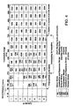
- FIG. 4 illustrates the startup process of a 351 cubic inch V8 spark ignition four-stroke cycle engine having a conventional forward gear firing order of 1 -8-4-3-6-5-7-2 and required one or more pistons to be within a predetermined crankshaft angle range of 25-155 CA degrees after TDC.
- a control unit (not shown) receives a signal to start the motor, it begins to operate the engine in a start-up mode. At the beginning of the start-up mode, the control unit identifies cylinders 1 and 6 as being at 90 CA degrees, which is within a predetermined crankshaft angle range of 25-155 CA degrees after TDC and selects these two cylinders for firing. Thus, in this example, ⁇ equals 90 CA degrees.
- the selected cylinders can be at any angle within the predetermined range.
- the very first stroke for cylinders 1 and 6 (200-1, 200-1) does not start from TDC, but from a predetermined position ( ⁇ crank angle degrees) that falls within the predetermined range of acceptable positions.
- the next stroke of the start up cycle begins when one or more pistons move to TDC and thus the very first stroke should produce sufficient kinetic energy to rotate the crankshaft such that at least one piston moves to TDC. Since cylinders 1 and 6 are at 90 crank angle degrees, they must rotate the cran kshaft 90 CA degrees in order to move cylinder 5 into place. It should also be understood that cylinders 1 and 6 have a fresh charge that was entrapped by a scavenging process (described more below) prior to the engine being stopped and thus do not require an intake stroke to draw a fresh charge.
- the control unit injects a suitable amount of fuel to each of the cylinders 1 and 6, and ignites the spark plug to fire the cylinders.
- Cylinders 1 and 6 thus start the startup combustion and expansion strokes (CES) (230-1, 230-2), without pre-compression, and the kinetic energy generated will push the piston and cause the crankshaft to rotate. As discussed before, it only takes about 90° (180°- ⁇ ) crank angle for cylinder 1 and 6 to complete the first stroke of their very first special two - stroke cycle.
- CES startup combustion and expansion strokes
- the intake valves of cylinders 5 and 8 stay open to suck fresh charge from the intake manifold (210-1, 210-2).
- the control unit closes the intake valve of cylinder 8, injects a suitable amount of fuel into cylinder 8, and ignites the fuel air mixture to fire cylinder 8 (230 -3).
- cylinder 5 could have been fired instead of or in addition to cylinder 8.
- cylinder 5 continues its normal intake stroke until its piston moves down to its BDC (230 -4).
- the fully charged cylinder 5 will be compressed in its follow-up stroke (CS4, 241-1, 241-2), which will become the first normal combustion stroke (CE4, 250).
- the special two-stroke cycle does not compress the fuel-air mixture is has a lower thermodynamic efficiency than a conventional four-stroke cycle in which the fuel-air mixture is compressed. Accordingly, it is generally preferable to start the transition process as soon as it is determined that the piston -connecting-rod-crankshaft mechanism of the engine can provide sufficient kinetic energy for a cylinder (cylinder 5 in this example) to operate in a normal four-stroke cycle successfully. In some situations, such as in a cold weather environment, the engine may be more difficult to start and the control unit may need to build up more kinetic energy than normally would be required in a warmer environment to complete a single compression stroke.
- cylinder 8 when cylinder 8 is combusting and expanding at its startup cycle (230-3), it adds more kinetic energy to the piston-connecting-rod-crankshaft mechanism.
- the control unit begins a startup intake stroke in cylinder 4 (221-1) and an intake stroke in cylinder 7 (221 -2).
- the combustion and expansion stroke (CES) of cylinder 8 (230-3) is followed by the startup combustion and expansion stroke (CES) of cylinder 4 (230-4), which is further followed by the startup combustion and expansion process (CES) of cylinder 3 (230 -5), which is further followed by the startup combustion/expansion process (CES) of cylinder 6 (230-6). All these startup combustion/expansion strokes (CES) add more and more kinetic energy to the piston-connecting-rod-crankshaft mechanism, and help transition the engine from start-up mode to normal four-stroke cycle operation mode.
- CES startup combustion and expansion strokes
- cylinders 1 and 6 continue a startup exhaust stroke
- cylinder 8 begins a startup exhaust stroke
- cylinder 2 begins a normal intake stroke
- cylinder 3 begins a special intake stroke
- cylinder 7 continues an intake stroke
- cylinder 4 begins a startup combustion and expansion stroke. Additional ly, sufficient kinetic energy has accumulated within the engine such that cylinder 5 begins a compression stroke (241-1).
- cylinder 5 begins its compression stroke the engine begins its transition from the startup mode to normal operating mode.
- cylinders 1 and 6 begin another intake stroke
- cylinder 2 continues an intake stroke
- cylinder 3 begins a startup combustion and expansion stroke
- cylinder 4 begins a startup exhaust stroke
- cylinder 5 continues a compression stroke
- cylinder 7 begins a compression stroke (240 -1)
- cylinder 8 continues its startup exhaust stroke.
- cylinder 1 continues its intake stroke
- cylinder 2 begins its compression stroke (240-2)
- cylinder 3 starts its startup exhaust stroke
- cylinder 4 continues its startup exhaust stroke
- cylinders 5 and 6 start a combustion and expansion stroke (startup CES 230-6 for cylinder 6, normal combustion and expansion stroke CE4 250 for cylinder 5)
- cylinder 7 begins a com pression stroke
- cylinder 8 starts an intake stroke. Note that cylinder 5 is fired following a compression stroke and is thus fired as part of the normal operating mode whereas the firing of cylinder 6 does not follow a compression stroke and is thus fired as part of the startup mode.
- cylinder 1 begins a compression stroke (240-3)
- cylinder 2 continues a compression stroke
- cylinder 3 continues a startup exhaust stroke
- cylinder 4 begins an intake stroke
- cylinder 5 continues a combustion and expansion stroke
- cylinder 6 begins a startup exhaust stroke
- cylinder 7 begins a combustion and expansion stroke
- cylinder 8 continues an intake stroke.
- cylinder 1 continues a compression stroke
- cylinder 2 begins a combustion and expansion stroke
- cylinder 3 begins an intake stroke
- cylinder 4 continues an intake stroke
- cylinder 5 begins an exhaust stroke
- cylinder 6 continues the startup exhaust stroke
- cylinder 7 continues a combustion and expansion stroke
- cylinder 8 begins a compression stroke (240 -4).
- the control unit 70 begins completely operating the engine in its normal four-stroke operating mode, thus marking the end of the start up mode.
- At least one piston within a cylinder must be in the predetermined crankshaft angle range in order to provide it the ability to rotate the crankshaft in the proper direction when the cylinder is fired. Additionally, there should be a fresh charge, rather than combustion residue, entrapped within the cylinders.
- the control unit may be configured to engage in a controlled braking process which stop s the engine such that at least one piston stops within the predetermined CA range, and also provides fresh charge in the corresponding cylinder.
- the pumping work contributed from compression stroke of individual cylinder can be adjusted through changing the effective compression ratio of that cylinder, which can be further achieved through manipulating the intake and exhaust valve event parameters (mainly valve timing parameters such as valve event angle), of that cylinder.
- the pumping work contributed from vacuum stroke of individual cylinder can also be adjusted by manipulating the intake and exhaust valve event parameters, as will be described in more detail below.
- a cylinder conducts a compressing stroke and a vacuuming stroke alternatively.
- the cylinder entraps a greater amount of air before the com pressing process starts.
- the cylinder expels a greater amount of air before the vacuuming process starts. Therefore, the cylinder conducts a breathing process during which the cylinder briefly opens its valve (or valves) around TDC and BDC to equalize its pressure to the ambient pressure in order to produce large pumping work in the follow-up strokes.
- the all valves in a cylinder i.e., both intake and exhaust valves
- a re widely opened i.e., maximum valve lift
- the cylinder will likely not be thoroughly scavenged. Scavenging refers to the process of introducing a fresh charge through the intake valve to help expel burned gases through the exhaust valve. By thorough scavenging the cylinders, a fresh charge can be provided within a cylinder, which is necessary to restart the engine.
- the intake and exhaust valves are controlled to provide a controlled level of pumping work, while also ensuring a thorough scavenging of the cylinders.
- FIG. 5A illustrates valve timing events during the braking process which produce a maximized amount of pumping work while ensuring an adequate scavenging of the cylinder.
- the exhaust valve of this cylinder is widely (i.e., maximum valve lift) opened just before the piston reaches its TDC, i.e., at ⁇ 1 degree crank angle before TDC, and releases the compressed charge from the last braking stroke to the exhaust system. It should be noted that it is not necessary to always have the maximum valve lift, but the valve lift parameter may be adjusted depending on the desired pumping work and other factors such as the engine speed.
- the exhaust valve closes shortly after the piston passes its TDC, i.e., at ⁇ 2 degree crank angle after the TDC.
- the cylinder Upon closing of the exhaust valve, the cylinder traps a small amount of charge. As the piston moves towards its BDC from TDC, the cylinder is vacuumed and high pumping work is generated until the piston moves close enough to its BDC where the intake valve widely opens, i.e., ⁇ 1 degree crank angle before BDC, to introduce fresh charge from the intake manifold. The intake valve is closed shortly after the piston passes its BDC, i.e., ⁇ 2 degree crank angle after BDC. Upon the intake valve's closing, the cylinder entraps sufficient fresh charge from the intake manifold. As the piston moves back toward its TDC from BDC, the entrapped fresh charge is compressed, thus generating high pumping work.
- FIG. 5B illustrates valve timing events which produce minimized amount of pumping work while ensuring adequate scavenging of the cylinder.
- Desirable valve event parameters maximizing pumping work while also ensuring an adequate scavenging of the cylinder may vary with the design of the particular engine. Such parameters can be determined through simulation, engine testing, or other techniques known to persons of ordinary skill in the art. For the whole engine, the total amount of pumping work can be controlled through by the pumping work generated by each of the cylinders. It should be noted that it is not necessary to regulate the pumping work generated by every single cylinder.
- a controlled engine braking process 600 uses pumping work adjustment to stop an engine such that at least one of the engine's pistons stops in a predetermined location.
- a control unit initially receives a command to stop the engine (602) and, in response, the control unit transitions the engine from normal four-stroke operating mode to a controlled braking mode (604).
- the control unit Upon entering the controlled braking mode, the control unit stops the injection of fuel into the cylinders (606). If fuel-air mixture is within a cylinder before the engine transitions to braking mode, the control unit may ignite this cylinder to combust the mixture and finish the last normal combustion stroke. In one embodiment, cylinders that have already finished their last exhaust stroke enter braking mode immediately and pumping work may be adjusted to these cylinders while other cylinders are still being fired. In another embodiment, the cylinders will enter braking mode after all cylinders finish the last normal combustion stroke. In yet another embodiment, the control unit waits until all cylinders have stopped firing before transitioning the engine from normal four-stroke operating mode to a controlled braking mode.
- the control unit After entering the braking mode, the control unit enters a first braking stage (608) in which it actuates the valves of on e or more cylinders to produce pumping work over one or more braking strokes to decrease the speed of the engine from an entering speed (shown as the speed at point A in FIG. 6B) to a target speed (shown as the speed at point D in FIG. 6B) that is within a range of desired target speeds (shown as the shaded region 612 in FIG. 6B).
- a first braking stage 608 in which it actuates the valves of on e or more cylinders to produce pumping work over one or more braking strokes to decrease the speed of the engine from an entering speed (shown as the speed at point A in FIG. 6B) to a target speed (shown as the speed at point D in FIG. 6B) that is within a range of desired target speeds (shown as the shaded region 612 in FIG. 6B).
- the target speed is preferably selected to be at the midpoint within the range of desired target speeds in order to provide for the maximum variance between the target speed and the actual speed after completing the braking strokes of the first stage while maintaining the actual speed within the range of desired target speeds.
- the range of desired target speeds is a range of engine speeds for which valve parameters, which have been determined through simulation or actual engine testing, produce sufficient pumping work to stop the engine in a single stroke, so that the engine last stroke (during which the engine stops) angle falls within a range of desired crankshaft angles.
- the desired range of crankshaft angles are those crankshaft angles which have at least one piston positioned within a predetermined CA range relative to top dead center where the piston has sufficient mechanical advantage to rotate the crankshaft (e.g., 25-155 crankshaft angle degrees after TDC).
- the upper bound of the target speed range is the greatest entering speed (i.e., the speed of the engine prior to entering the last braking stroke) at which the engine can be stopped within the desire crankshaft range u sing maximized pumping work.
- the lower bound of the target speed range is the smallest entering speed at which the engine can be stopped within the desired crankshaft range using minimized pumping work.
- the range of desired target speeds is between 50-500 RPM since pumping work may be applied at any speed in this range to cause the crankshaft to stop in the desired position.
- valve event parameters to produce the amount of pumping work required for this range of engine speeds may be determined dynamically through a closed-form calculation or statically through a look-up table or other data structure in which valve parameters corresponding to different amounts of pumping work have been statically computed and stored in memory.
- valve event parameters may be dynamically adjusted in real-time, based on engine speed monitoring and a predefined feedback control law, to reduce the engine speed.
- the control unit first measures the entering speed of the engine, which is the speed of the engine (e.g., revolutions per minute of the engine) before entering a braking stroke. The control unit then computes the total amount of pumping work required to reduce the engine speed from the entering speed to the target speed. After computing the total amount of pumping work required to reduce the engine speed from the entering speed to the target speed, the control unit determines the number of braking strokes required to decrease the entering speed to a speed within the target speed range. It should be noted that the total amount of pumping work required and the number of braking strokes required also depend on the valve event parameters.
- the number of braking strokes required will be less than when the minimum pumping work of each braking stroke is used.
- the total pumping work is preferably evenly distributed among the determined number of braking strokes. For example, as shown in FIG. 6B, the pumping work required to reduce the engine's speed from the entering speed (i.e., the speed at point A) to the target speed (i.e., the speed at point D) is evenly divided among three braking strokes.
- the control unit determines, based on the computed pumping work required for each one of the three braking strokes, the valve event parameters that produce the desired amount of pumping work to slow the engine during each braking stroke.
- the determination of the valve event parameters required to produce the computed amount of pumping work may be made through a closed-form calculation computed dynamically or by way of a look-up table in which valve event parameters corresponding to different amounts of pumping work have been pre-computed and stored in memory.
- the control unit applies the requisite pumping work over the braking strokes to decrease the engine speed to the target speed.
- the controlled engine braking process (600) After decreasing the engine speed from an entering speed to the target speed through one or more braking strokes, the controlled engine braking process (600) then enters the second braking stage (610).
- the control unit controls the valve event parameters to apply the proper amount of pumping work to stop the engine within the range of desired crankshaft angles.
- the control unit may determine the proper valve event parameters through a valve event parameters map, which maps entering speed to the last stroke angle with various valve event parameters.
- a control unit may be configured to estimate the amount of friction work that is occurring within the engine during the first stage of the braking process based on measured crankshaft speed in response to various valve events and other parameters.
- the control unit may further be configured to adjust valve event parameters based on the estimated friction work.
- an engine employs a process that adaptively compensates for friction variation in the engine by first predicting the residue speed of a braking stroke based on the entering speed of the braking stroke and expected pumping work during the braking stroke. Then, at the end of the braking stroke, the process compares the actual residual speed to the predicted residual speed to estimate the friction variation, assuming that the deviation between the two is due to an overest imation or underestimation of the friction work present in the cylinders. If the estimated friction work is higher or lower than its normal value, the braking process can adaptively decrease or increase the amount of applied pumping work (by adjusting the valve parameters) during next braking stroke.
- an engine employs a process that adaptively compensates for friction variation in the engine by first applying the minimum pumping work in the very first braking stroke of the first stage of the braking operation mode, so that engine friction dominates that braking stroke.
- the process samples the engine's speeds and derives the engine's acceleration and inertia from the sampled speeds.
- the engine's friction is then estimated based on the inertia and acceleration of the engine.
- the estimated engine friction is then compared to a normal friction value, and the pumping work applied to each following braking stroke is adjusted by adjusting the valve parameters to compensate for the friction variation. For example, if the actual friction is lower than the normal value, the process can increase the pumping work for the braking strokes to achieve the expected residual speed.
- an engine may emp loy a process that adjusts for friction variation in the engine by comparing the actual last stroke angle to the predicted last stroke angle, and subsequently adjusting the valve parameters to compensate for the friction variation in the next braking proce ss.
- An engine may also be provided with a process that uses stored energy, such as pressure energy of a fluid in a cylinder, to adjust the crank angle of the engine after it stops.
- This stored energy can be used to push the engine to rotate backward if the last stroke angle is smaller than 180 CA, or forward when the last stroke angle is larger than 180 CA, which makes the engine configuration at TDC or BDC unstable.
- the process fine-tunes the last stroke angle using this stored energy by either pus hing the last stroke angle to within the predetermined range and/or adjusting the last stroke angle to be at or close to an optimal angle.
- the self-starting process can be used along with the controlled braking process that sets at least one piston at the predetermined range and provides fresh charge to the corresponding cylinders to prepare for the self-starting process.
Applications Claiming Priority (2)
| Application Number | Priority Date | Filing Date | Title |
|---|---|---|---|
| US810930 | 2004-03-26 | ||
| US10/810,930 US7082899B2 (en) | 2004-03-26 | 2004-03-26 | Controlled starting and braking of an internal combustion engine |
Publications (2)
| Publication Number | Publication Date |
|---|---|
| EP1586767A2 true EP1586767A2 (fr) | 2005-10-19 |
| EP1586767A3 EP1586767A3 (fr) | 2007-10-24 |
Family
ID=34938685
Family Applications (1)
| Application Number | Title | Priority Date | Filing Date |
|---|---|---|---|
| EP05100930A Withdrawn EP1586767A3 (fr) | 2004-03-26 | 2005-02-10 | Démarrage et freinage commandés pour moteur à combustion interne |
Country Status (5)
| Country | Link |
|---|---|
| US (2) | US7082899B2 (fr) |
| EP (1) | EP1586767A3 (fr) |
| JP (1) | JP2005282574A (fr) |
| CN (1) | CN1673510B (fr) |
| HK (1) | HK1079834B (fr) |
Cited By (4)
| Publication number | Priority date | Publication date | Assignee | Title |
|---|---|---|---|---|
| US7234442B2 (en) | 2004-03-26 | 2007-06-26 | Bose Corporation | Controlled starting and braking of an internal combustion engine |
| WO2007099003A1 (fr) * | 2006-02-24 | 2007-09-07 | Robert Bosch Gmbh | Groupe propulseur hybride muni d'un accouplement de séparation d'assistance AVEC un démarrage direct |
| EP2067954A1 (fr) | 2007-12-03 | 2009-06-10 | Caterpillar Motoren GmbH & Co. KG | Chambre de précombustion dotée d'un démarrage initié par la combustion |
| DE102015201839B4 (de) | 2014-02-05 | 2023-10-12 | Ford Global Technologies, Llc | Verfahren und System zum Auswählen eines Zylinders für das Starten einer Kraftmaschine |
Families Citing this family (48)
| Publication number | Priority date | Publication date | Assignee | Title |
|---|---|---|---|---|
| DE10322305A1 (de) * | 2003-05-17 | 2004-12-02 | Daimlerchrysler Ag | Verfahren zum Abstellen einer Brennkraftmaschine |
| US7165391B2 (en) * | 2004-03-19 | 2007-01-23 | Ford Global Technologies, Llc | Method to reduce engine emissions for an engine capable of multi-stroke operation and having a catalyst |
| DE102004037167A1 (de) * | 2004-07-30 | 2006-03-23 | Robert Bosch Gmbh | Vorrichtung und Verfahren zur Steuerung einer Brennkraftmaschine |
| JP2006070793A (ja) * | 2004-09-01 | 2006-03-16 | Toyota Motor Corp | 内燃機関の制御装置 |
| US7104235B2 (en) * | 2004-11-01 | 2006-09-12 | Ford Global Technologies, Llc | Starting a camless engine from rest |
| JP4557816B2 (ja) * | 2004-12-17 | 2010-10-06 | トヨタ自動車株式会社 | エンジン始動制御装置、その方法及びそれを搭載した車両 |
| US7278388B2 (en) * | 2005-05-12 | 2007-10-09 | Ford Global Technologies, Llc | Engine starting for engine having adjustable valve operation |
| US8763582B2 (en) * | 2005-05-12 | 2014-07-01 | Ford Global Technologies, Llc | Engine starting for engine having adjustable valve operation and port fuel injection |
| US7461621B2 (en) * | 2005-09-22 | 2008-12-09 | Mazda Motor Corporation | Method of starting spark ignition engine without using starter motor |
| US7373928B2 (en) * | 2006-05-31 | 2008-05-20 | Joseph Thomas | Method for starting a direct injection engine |
| US7930087B2 (en) * | 2006-08-17 | 2011-04-19 | Ford Global Technologies, Llc | Vehicle braking control |
| US7499793B2 (en) * | 2007-05-14 | 2009-03-03 | Delphi Technologies, Inc. | System for discrimination of spurious crank encoder signals |
| DE602007007586D1 (de) * | 2007-05-25 | 2010-08-19 | Magneti Marelli Spa | Regelverfahren für ein Kraftfahrzeug welches im Falle eines Defektes einen Betrieb des Fahrzeugs mit reduzierter Leistung bewirkt |
| JP4755154B2 (ja) * | 2007-08-30 | 2011-08-24 | 三菱重工業株式会社 | ガスエンジンの始動制御方法及び装置 |
| JP4849040B2 (ja) * | 2007-09-10 | 2011-12-28 | マツダ株式会社 | ディーゼルエンジンの制御装置 |
| US7717077B2 (en) * | 2007-11-13 | 2010-05-18 | Gm Global Technology Operations, Inc. | Internal combustion engine starting system and method |
| US7565896B1 (en) * | 2008-02-28 | 2009-07-28 | Jacobs Vehicle Systems, Inc. | Method for variable valve actuation to provide positive power and engine braking |
| US20090229545A1 (en) * | 2008-03-13 | 2009-09-17 | Compressco, Inc. | Crankshaft for integral gas compressor and internal combustion engine |
| US8197383B2 (en) * | 2008-06-25 | 2012-06-12 | Ford Global Technologies, Llc | Multi-stroke hybrid propulsion system |
| JP5114340B2 (ja) * | 2008-08-08 | 2013-01-09 | 株式会社デンソー | エンジン停止制御装置 |
| JP4529190B2 (ja) * | 2008-08-08 | 2010-08-25 | 株式会社デンソー | エンジン停止制御装置 |
| DE102009035160B4 (de) * | 2009-03-31 | 2021-02-11 | Dr. Ing. H.C. F. Porsche Aktiengesellschaft | Verfahren zum Starten eines Verbrennungsmotors |
| JP4505546B1 (ja) * | 2009-12-07 | 2010-07-21 | 正夫 櫻井 | 可変バルブタイミング装置 |
| US8752519B2 (en) * | 2009-12-15 | 2014-06-17 | GM Global Technology Operations LLC | Air assist start stop methods and systems |
| GB2478699A (en) * | 2010-03-09 | 2011-09-21 | Gm Global Tech Operations Inc | A method for positioning the crank angle in a stop condition in an internal combustion engine |
| US8770173B2 (en) * | 2010-04-14 | 2014-07-08 | GM Global Technology Operations LLC | Multi-phase engine stop position control |
| US8543318B2 (en) * | 2010-06-01 | 2013-09-24 | GM Global Technology Operations LLC | Controlled engine shutdown system for a stop-start system and a hybrid electric vehicle |
| US20130166177A1 (en) * | 2010-09-10 | 2013-06-27 | Robert Bosch Gmbh | Method and device for controlling an internal combustion engine |
| US8667954B2 (en) * | 2011-09-21 | 2014-03-11 | GM Global Technology Operations LLC | Simultaneously firing two cylinders of an even firing camless engine |
| DE112013006969T5 (de) * | 2013-04-22 | 2016-01-07 | Mitsubishi Electric Corporation | Motorstoppsteuervorrichtung und Motorstoppsteuerverfahren |
| GB2524318B (en) | 2014-03-21 | 2017-12-13 | Jaguar Land Rover Ltd | Method of injecting fuel into an internal combustion engine |
| JP6191552B2 (ja) * | 2014-06-19 | 2017-09-06 | トヨタ自動車株式会社 | 内燃機関の自動停止制御装置 |
| DE102014213034A1 (de) * | 2014-07-04 | 2016-01-07 | Bayerische Motoren Werke Aktiengesellschaft | Verfahren zum Starten eines Verbrennungsmotors |
| RU2647950C1 (ru) * | 2016-11-02 | 2018-03-21 | Анатолий Александрович Рыбаков | Способ реверсирования вращения вала отбора мощности двухтактного двигателя с внешней камерой сгорания |
| CN106555682A (zh) * | 2016-11-16 | 2017-04-05 | 中国北方发动机研究所(天津) | 一种降低柴油机启动工况有害排放的可变气门控制方法 |
| RU2637594C1 (ru) * | 2016-11-23 | 2017-12-05 | Анатолий Александрович Рыбаков | Способ пуска и реверсирования тандемного двухтактного двигателя с внешней камерой сгорания |
| CN106870173B (zh) * | 2017-04-12 | 2023-09-19 | 吉林大学 | 一种发动机停机相位控制机构 |
| US10816438B2 (en) * | 2017-11-14 | 2020-10-27 | Tula Technology, Inc. | Machine learning for misfire detection in a dynamic firing level modulation controlled engine of a vehicle |
| US11125175B2 (en) | 2017-11-14 | 2021-09-21 | Tula Technology, Inc. | Machine learning for misfire detection in a dynamic firing level modulation controlled engine of a vehicle |
| CN109540512B (zh) * | 2018-11-29 | 2020-07-24 | 安徽江淮汽车集团股份有限公司 | 一种检测未知结构飞轮端齿数的方法 |
| CN110425071B (zh) * | 2019-07-19 | 2021-06-11 | 重庆巩诚投资有限公司 | 发动机起动控制方法 |
| US10954830B1 (en) * | 2019-08-28 | 2021-03-23 | GM Global Technology Operations LLC | Cam phaser control systems and methods for engine off conditions |
| CN110700956B (zh) * | 2019-09-10 | 2022-07-19 | 吉利汽车研究院(宁波)有限公司 | 一种发动机点火控制方法及装置 |
| US11434839B2 (en) | 2020-12-30 | 2022-09-06 | Tula Technology, Inc. | Use of machine learning for detecting cylinder intake and/or exhaust valve faults during operation of an internal combustion engine |
| WO2022150404A1 (fr) | 2021-01-11 | 2022-07-14 | Tula Technology Inc. | Diagnostic et gestion de défaillance de soupape d'échappement |
| CN113266444A (zh) * | 2021-04-29 | 2021-08-17 | 广西玉柴机器股份有限公司 | 一种发动机缸内制动的控制方法及系统 |
| US11466634B1 (en) | 2022-01-26 | 2022-10-11 | Ford Global Technologies, Llc | Methods and system for starting an engine |
| US20230392559A1 (en) * | 2022-06-02 | 2023-12-07 | GM Global Technology Operations LLC | Engine exhaust braking system for equalizing pressures across exhaust valves during intake strokes |
Family Cites Families (22)
| Publication number | Priority date | Publication date | Assignee | Title |
|---|---|---|---|---|
| US1676591A (en) | 1927-04-19 | 1928-07-10 | John H Weller | Vaporized gas and air starter for automobiles and the like |
| US4364336A (en) | 1972-10-27 | 1982-12-21 | Skala Stephen F | Self starting of internal combustion engines based on reactor |
| US4009695A (en) | 1972-11-14 | 1977-03-01 | Ule Louis A | Programmed valve system for internal combustion engine |
| US4462348A (en) | 1981-08-31 | 1984-07-31 | Ford Motor Company | Engine starting system |
| JPS63198779A (ja) * | 1987-02-13 | 1988-08-17 | Shigeru Takeuchi | ガソリンエンジン始動装置 |
| US5074263A (en) | 1990-02-02 | 1991-12-24 | Emerson Charles E | Stop/start control system for an internal combustion engine |
| CA2012027C (fr) | 1990-03-13 | 1996-04-23 | Albert D'amours | Moteur a combustion interne a inversion du sens de rotation |
| FI913816A (fi) | 1991-08-12 | 1993-02-13 | Igor Mikhaltsev | Foerfarande och arrangemang foer starning av foerbraenningsmotor |
| DE4439849A1 (de) | 1994-11-08 | 1996-05-09 | Bosch Gmbh Robert | Verfahren und Vorrichtung zum Starten einer Brennkraftmaschine |
| US6098585A (en) | 1997-08-11 | 2000-08-08 | Ford Global Technologies, Inc. | Multi-cylinder four stroke direct injection spark ignition engine |
| DE19746119A1 (de) * | 1997-10-18 | 1999-04-22 | Bosch Gmbh Robert | Verfahren zum Starten einer Brennkraftmaschine |
| DE19825411C1 (de) | 1998-06-06 | 1999-10-07 | Daimler Chrysler Ag | Umsteuerbare Hubkolbenbrennkraftmaschine |
| US6125808A (en) | 1999-04-07 | 2000-10-03 | Timewell; Richard R. | Apparatus and method for starting an internal combustion engine |
| DE19955857A1 (de) * | 1999-11-20 | 2001-06-07 | Bosch Gmbh Robert | Verfahren zum Starten einer Brennkraftmaschine insbesondere eines Kraftfahrzeugs |
| DE19960984A1 (de) * | 1999-12-17 | 2001-06-21 | Bosch Gmbh Robert | Verfahren zur Auslaufsteuerung einer Brennkraftmaschine |
| DE10020104A1 (de) * | 2000-04-22 | 2001-10-31 | Bosch Gmbh Robert | Verfahren zum Starten einer mehrzylindrigen Brennkraftmaschine |
| DE10020325A1 (de) * | 2000-04-26 | 2001-11-08 | Bosch Gmbh Robert | Verfahren zum Starten einer mehrzylindrigen Brennkraftmaschine |
| JP3939905B2 (ja) * | 2000-07-27 | 2007-07-04 | 株式会社日立製作所 | エンジン始動装置 |
| DE10111928B4 (de) * | 2001-03-13 | 2008-09-04 | Robert Bosch Gmbh | Verfahren zum anlasserfreien Starten einer mehrzylindrigen Brennkraftmaschine |
| EP1367246B1 (fr) * | 2002-05-14 | 2006-03-08 | Ford Global Technologies, LLC, A subsidary of Ford Motor Company | Méthod pour arrêter un moteur à combustion interne et faciliter son démarrage |
| US7027911B2 (en) * | 2003-01-30 | 2006-04-11 | Denso Corporation | Apparatus for controlling engine rotation stop by estimating kinetic energy and stop position |
| US7082899B2 (en) | 2004-03-26 | 2006-08-01 | Bose Corporation | Controlled starting and braking of an internal combustion engine |
-
2004
- 2004-03-26 US US10/810,930 patent/US7082899B2/en not_active Expired - Fee Related
-
2005
- 2005-02-10 EP EP05100930A patent/EP1586767A3/fr not_active Withdrawn
- 2005-03-25 CN CN200510059258XA patent/CN1673510B/zh not_active Expired - Fee Related
- 2005-03-28 JP JP2005091092A patent/JP2005282574A/ja active Pending
- 2005-12-30 HK HK05112189.1A patent/HK1079834B/zh not_active IP Right Cessation
-
2006
- 2006-06-01 US US11/445,058 patent/US7234442B2/en not_active Expired - Fee Related
Cited By (5)
| Publication number | Priority date | Publication date | Assignee | Title |
|---|---|---|---|---|
| US7234442B2 (en) | 2004-03-26 | 2007-06-26 | Bose Corporation | Controlled starting and braking of an internal combustion engine |
| WO2007099003A1 (fr) * | 2006-02-24 | 2007-09-07 | Robert Bosch Gmbh | Groupe propulseur hybride muni d'un accouplement de séparation d'assistance AVEC un démarrage direct |
| US8480536B2 (en) | 2006-02-24 | 2013-07-09 | Robert Bosch Gmbh | Hybrid drive having a separating clutch which assists a direct start |
| EP2067954A1 (fr) | 2007-12-03 | 2009-06-10 | Caterpillar Motoren GmbH & Co. KG | Chambre de précombustion dotée d'un démarrage initié par la combustion |
| DE102015201839B4 (de) | 2014-02-05 | 2023-10-12 | Ford Global Technologies, Llc | Verfahren und System zum Auswählen eines Zylinders für das Starten einer Kraftmaschine |
Also Published As
| Publication number | Publication date |
|---|---|
| JP2005282574A (ja) | 2005-10-13 |
| HK1079834B (zh) | 2011-05-13 |
| HK1079834A1 (en) | 2006-04-13 |
| US20060213481A1 (en) | 2006-09-28 |
| US7082899B2 (en) | 2006-08-01 |
| EP1586767A3 (fr) | 2007-10-24 |
| US20050211194A1 (en) | 2005-09-29 |
| CN1673510B (zh) | 2010-12-08 |
| US7234442B2 (en) | 2007-06-26 |
| CN1673510A (zh) | 2005-09-28 |
Similar Documents
| Publication | Publication Date | Title |
|---|---|---|
| EP1586767A2 (fr) | Démarrage et freinage commandés pour moteur à combustion interne | |
| JP2954350B2 (ja) | 内燃機関の作動モードを制御する装置 | |
| US7167789B1 (en) | Variable compression ratio internal combustion engine | |
| US6499458B1 (en) | Method for operating a four-stroke reciprocating internal combustion engine | |
| US5553579A (en) | Fuel injection system for two-cycle engine | |
| JPH05179986A (ja) | 内燃機関の運転方法 | |
| US6474291B2 (en) | Clean shutdown for internal combustion engine with variable valve timing | |
| JP2006132535A (ja) | 内燃機関、内燃機関の制御方法、内燃機関の制御に用いられるコンピューター読取り可能な記憶媒体、及び、エンジン制御用コンピューター・プログラム | |
| US5205152A (en) | Engine operation and testing using fully flexible valve and injection events | |
| EP0427334A1 (fr) | Moteur deux-temps avec soupape à calage variable | |
| US8412441B1 (en) | Mixed cycle compression ignition engines and methods | |
| JP3841058B2 (ja) | エンジンの始動装置 | |
| JP4103649B2 (ja) | エンジンの始動装置 | |
| JP5168065B2 (ja) | ディーゼルエンジンの制御装置及びディーゼルエンジンの制御方法 | |
| US6962136B2 (en) | Methods for starting a multi-cylinder internal combustion engine | |
| JP4637788B2 (ja) | 可変バルブを備えたエンジンの制御方法 | |
| US7506625B2 (en) | Method and apparatus for controlling engine valve timing | |
| JP4075666B2 (ja) | エンジンの始動装置 | |
| JP3966209B2 (ja) | エンジンの始動装置 | |
| JP4207627B2 (ja) | エンジンの始動装置 | |
| JP4144421B2 (ja) | 内燃機関の制御装置 | |
| RU2435065C2 (ru) | Двигатели с высокими эксплуатационными характеристиками и малыми выбросами, многоцилиндровые двигатели и способы их эксплуатации | |
| JP4103664B2 (ja) | エンジンの始動装置 | |
| WO1996001939A1 (fr) | Moteur a explosion a pistons alternatifs a aspiration limitee | |
| JP4277555B2 (ja) | エンジンの始動装置 |
Legal Events
| Date | Code | Title | Description |
|---|---|---|---|
| PUAI | Public reference made under article 153(3) epc to a published international application that has entered the european phase |
Free format text: ORIGINAL CODE: 0009012 |
|
| AK | Designated contracting states |
Kind code of ref document: A2 Designated state(s): AT BE BG CH CY CZ DE DK EE ES FI FR GB GR HU IE IS IT LI LT LU MC NL PL PT RO SE SI SK TR |
|
| AX | Request for extension of the european patent |
Extension state: AL BA HR LV MK YU |
|
| PUAL | Search report despatched |
Free format text: ORIGINAL CODE: 0009013 |
|
| AK | Designated contracting states |
Kind code of ref document: A3 Designated state(s): AT BE BG CH CY CZ DE DK EE ES FI FR GB GR HU IE IS IT LI LT LU MC NL PL PT RO SE SI SK TR |
|
| AX | Request for extension of the european patent |
Extension state: AL BA HR LV MK YU |
|
| 17P | Request for examination filed |
Effective date: 20080331 |
|
| AKX | Designation fees paid |
Designated state(s): DE GB |
|
| 17Q | First examination report despatched |
Effective date: 20080917 |
|
| STAA | Information on the status of an ep patent application or granted ep patent |
Free format text: STATUS: THE APPLICATION IS DEEMED TO BE WITHDRAWN |
|
| 18D | Application deemed to be withdrawn |
Effective date: 20130409 |