EP1586540A1 - Regenerateur de residu liquide de machine d'impression et procede de regeneration de residu liquide - Google Patents
Regenerateur de residu liquide de machine d'impression et procede de regeneration de residu liquide Download PDFInfo
- Publication number
- EP1586540A1 EP1586540A1 EP03710437A EP03710437A EP1586540A1 EP 1586540 A1 EP1586540 A1 EP 1586540A1 EP 03710437 A EP03710437 A EP 03710437A EP 03710437 A EP03710437 A EP 03710437A EP 1586540 A1 EP1586540 A1 EP 1586540A1
- Authority
- EP
- European Patent Office
- Prior art keywords
- waste liquid
- printer
- vessel
- water
- ink pigment
- Prior art date
- Legal status (The legal status is an assumption and is not a legal conclusion. Google has not performed a legal analysis and makes no representation as to the accuracy of the status listed.)
- Withdrawn
Links
Images


Classifications
-
- C—CHEMISTRY; METALLURGY
- C02—TREATMENT OF WATER, WASTE WATER, SEWAGE, OR SLUDGE
- C02F—TREATMENT OF WATER, WASTE WATER, SEWAGE, OR SLUDGE
- C02F1/00—Treatment of water, waste water, or sewage
- C02F1/48—Treatment of water, waste water, or sewage with magnetic or electric fields
-
- B—PERFORMING OPERATIONS; TRANSPORTING
- B01—PHYSICAL OR CHEMICAL PROCESSES OR APPARATUS IN GENERAL
- B01D—SEPARATION
- B01D17/00—Separation of liquids, not provided for elsewhere, e.g. by thermal diffusion
- B01D17/02—Separation of non-miscible liquids
- B01D17/0208—Separation of non-miscible liquids by sedimentation
- B01D17/0214—Separation of non-miscible liquids by sedimentation with removal of one of the phases
-
- B—PERFORMING OPERATIONS; TRANSPORTING
- B01—PHYSICAL OR CHEMICAL PROCESSES OR APPARATUS IN GENERAL
- B01D—SEPARATION
- B01D17/00—Separation of liquids, not provided for elsewhere, e.g. by thermal diffusion
- B01D17/06—Separation of liquids from each other by electricity
-
- C—CHEMISTRY; METALLURGY
- C02—TREATMENT OF WATER, WASTE WATER, SEWAGE, OR SLUDGE
- C02F—TREATMENT OF WATER, WASTE WATER, SEWAGE, OR SLUDGE
- C02F1/00—Treatment of water, waste water, or sewage
- C02F1/46—Treatment of water, waste water, or sewage by electrochemical methods
- C02F1/461—Treatment of water, waste water, or sewage by electrochemical methods by electrolysis
- C02F1/463—Treatment of water, waste water, or sewage by electrochemical methods by electrolysis by electrocoagulation
-
- C—CHEMISTRY; METALLURGY
- C02—TREATMENT OF WATER, WASTE WATER, SEWAGE, OR SLUDGE
- C02F—TREATMENT OF WATER, WASTE WATER, SEWAGE, OR SLUDGE
- C02F1/00—Treatment of water, waste water, or sewage
- C02F1/46—Treatment of water, waste water, or sewage by electrochemical methods
- C02F1/469—Treatment of water, waste water, or sewage by electrochemical methods by electrochemical separation, e.g. by electro-osmosis, electrodialysis, electrophoresis
-
- B—PERFORMING OPERATIONS; TRANSPORTING
- B41—PRINTING; LINING MACHINES; TYPEWRITERS; STAMPS
- B41P—INDEXING SCHEME RELATING TO PRINTING, LINING MACHINES, TYPEWRITERS, AND TO STAMPS
- B41P2235/00—Cleaning
- B41P2235/30—Recovering used solvents or residues
-
- C—CHEMISTRY; METALLURGY
- C02—TREATMENT OF WATER, WASTE WATER, SEWAGE, OR SLUDGE
- C02F—TREATMENT OF WATER, WASTE WATER, SEWAGE, OR SLUDGE
- C02F1/00—Treatment of water, waste water, or sewage
- C02F1/46—Treatment of water, waste water, or sewage by electrochemical methods
- C02F1/469—Treatment of water, waste water, or sewage by electrochemical methods by electrochemical separation, e.g. by electro-osmosis, electrodialysis, electrophoresis
- C02F1/4696—Treatment of water, waste water, or sewage by electrochemical methods by electrochemical separation, e.g. by electro-osmosis, electrodialysis, electrophoresis electrophoresis
-
- C—CHEMISTRY; METALLURGY
- C02—TREATMENT OF WATER, WASTE WATER, SEWAGE, OR SLUDGE
- C02F—TREATMENT OF WATER, WASTE WATER, SEWAGE, OR SLUDGE
- C02F1/00—Treatment of water, waste water, or sewage
- C02F1/46—Treatment of water, waste water, or sewage by electrochemical methods
- C02F1/461—Treatment of water, waste water, or sewage by electrochemical methods by electrolysis
- C02F1/46104—Devices therefor; Their operating or servicing
- C02F1/46109—Electrodes
- C02F2001/46152—Electrodes characterised by the shape or form
- C02F2001/46157—Perforated or foraminous electrodes
-
- C—CHEMISTRY; METALLURGY
- C02—TREATMENT OF WATER, WASTE WATER, SEWAGE, OR SLUDGE
- C02F—TREATMENT OF WATER, WASTE WATER, SEWAGE, OR SLUDGE
- C02F2101/00—Nature of the contaminant
- C02F2101/30—Organic compounds
- C02F2101/308—Dyes; Colorants; Fluorescent agents
Definitions
- This invention relates to an apparatus and a method for regenerating waste liquid which is produced when a component of a printer to which ink adheres such as a blanket drum is cleaned, and more particularly to a waste liquid regeneration apparatus and a waste liquid regeneration method for a printer used to separate, from a system which includes charged ink pigment, insulating cleaning fluid and conductive water in a mixed state, the three components by means of a single apparatus.
- waste liquid is produced.
- a movement of applying some process to the waste liquid and disposing the processed waste liquid is promoted taking the terrestrial environment into consideration.
- a cost (disposal cost) is required for the disposal process, and besides, since a large amount of cleaning liquid is used to clean a blanket drum and like elements, a high running cost is required.
- FIG. 30 shows a general configuration of a waste liquid regeneration apparatus used by the settling method.
- the conventional waste liquid regeneration apparatus 51 includes a vessel 53 for storing cleaning waste liquid (waste liquid) 52.
- a bottom discharging pipe 54 is connected to the bottom wall of the vessel 53, and a side discharging pipe 55 is connected to a side wall of the vessel 53.
- a concentrated waste liquid recovery vessel 56 is disposed, and a regenerated cleaning liquid recovering vessel 57 is disposed below an exit of the side discharging pipe 55.
- an on-off valve 58 is connected to a passage of the bottom discharging pipe 54, and another on-off valve 59 is connected on the upstream side to a passage of the side discharging pipe 55 and a filter 60 is connected on the downstream side with respect to the on-off valve 59.
- waste liquid 52 after used to clean a blanket drum and other components of a printer is stored into the vessel 53 and some agent for promoting settling of ink pigment (sometimes referred to merely as pigment) 61 is added to the waste liquid 52 so that the ink pigment 61 is settled to the bottom of the vessel 53.
- the settled ink pigment that is, concentrated waste liquid 63
- supernatant liquid of the waste liquid 52 is filtered from the side discharging pipe 55 with the filter 60 to remove the ink pigment 61 and recovered into the regenerated cleaning liquid recovering vessel 57.
- Cleaning liquid 62 obtained in this manner is reused.
- the method described has a subject to be solved that exchange or cleaning of the filter 60 must be performed frequently.
- the present invention has been made in view of the subjects described above, and it is an object of the present invention to provide a waste liquid regeneration apparatus and a waste liquid regeneration method for a printer by which regeneration of cleaning liquid can be performed in a high efficiency to achieve reduction of the disposal cost for cleaning waste liquid and the running cost required for cleaning of the printer and besides improvement in productivity of the printer.
- the present invention adopts the following measures.
- a waste liquid regeneration apparatus for a printer is characterized in that the liquid regeneration apparatus comprises a vessel into which waste liquid containing ink pigment, water and cleaning fluid used in the printer is supplied, a metal electrode plate (for example, in the form of a wire mesh) disposed in the vessel for partitioning the inside of the vessel into a first chamber and a second chamber and for allowing the waste liquid to flow therethrough, a high-voltage power supply for applying a voltage to the metal electrode plate, and a grounding electrode connected to the first chamber.
- a metal electrode plate for example, in the form of a wire mesh
- an electrostatic field is generated in the waste liquid such that electrophoresis of the ink pigment by the electrostatic field can be utilized to electrostatically agglomerate the water and the ink pigment from within the waste liquid to separate the waste liquid into the cleaning liquid and the water and ink pigment. Accordingly, regeneration of the cleaning liquid can be performed in a high efficiency, and the disposal cost for the cleaning waste liquid can be reduced and the running cost required for cleaning of the printer can be reduced. As a result, improvement of the productivity of the printer can be achieved.
- the number of metal electrode plates is not limited to one, and one or a plurality of additional metal electrode plates for allowing the waste liquid to flow therethrough may be provided.
- the metal electrode plates are disposed in a juxtaposed and spaced relationship with from each other such that each of the metal electrode plates partitions the second chamber.
- the high-voltage power supply is connected to each of the metal electrode plates including the metal electrode plate which partitions the inside of the vessel into the first chamber and second chamber.
- a higher voltage is applied to any of the metal electrode plates as the distance from the grounding electrode to the metal electrode plate increases.
- a voltage is applied to each of the metal electrode plates from a corresponding one of the high-voltage power supplies such that a higher field intensity is generated by the metal electrode plate as the distance from the grounding electrode to the metal electrode plate decreases.
- a waste liquid supplying pipe for supplying the waste liquid is connected to the first chamber, and a cleaning fluid recovering pipe for recovering the regenerated cleaning fluid is connected to the second chamber.
- the waste liquid supplying pipe and the cleaning fluid recovering pipe are connected to a blanket drum cleaning apparatus for cleaning a blanket drum of the printer such that the waste liquid discharged from the blanket drum cleaning apparatus is supplied to the first chamber through the waste liquid supplying pipe and the cleaning fluid regenerated in the second chamber is recovered by the blanket drum cleaning apparatus through the cleaning fluid recovering pipe, while regeneration of the waste liquid is carried out, the regenerated cleaning liquid can be utilized to clean the blanket drum. Consequently, the operability is improved remarkably.
- the grounding electrode may be disposed substantially horizontally at a lower portion of the inside of the vessel, and the metal electrode plate or plates may be disposed substantially horizontally above the grounding electrode in the vessel.
- the cleaning liquid stays above the metal electrode plate or plates while the ink pigment and the water stay in the proximity of the grounding electrode below the metal electrode plate or plates. Therefore, recovery of the cleaning liquid, ink pigment and water can individually be performed readily, and reuse of the cleaning liquid and disposal of the water and the ink pigment can be performed readily and smoothly.
- a partition wall may be disposed in the proximity of a first side wall of the inside of the vessel while the metal electrode plate or plates are disposed between a second side wall opposing to the first side wall and the partition wall.
- the waste liquid regeneration apparatus for a printer may further comprise a scraping plate for scraping off ink pigment agglomerated on and adhering to the grounding electrode to remove the ink pigment from the grounding electrode.
- a scraping plate for scraping off ink pigment agglomerated on and adhering to the grounding electrode to remove the ink pigment from the grounding electrode.
- the grounding electrode may be formed as a metal sheet (for example, aluminum foil) which can be taken up in a coiled form.
- the waste liquid regeneration apparatus for a printer further comprises a delivering apparatus disposed outside the vessel for delivering the metal sheet and a take-up apparatus provided outside the vessel for taking up the metal sheet after the metal sheet is delivered from the delivering apparatus and used in the vessel, recovery and disposal of the ink pigment can be performed further readily and contribution also to prevention of contamination of the inside of the vessel and purification of the cleaning liquid to be reused is achieved.
- the grounding electrode may be formed as a rotatable metal disc, and a blade may be provided in sliding contact with the metal disc for scraping off the ink pigment adhering to the outside surface of the metal disc.
- the grounding electrode maybe formed as an endless metal sheet, and the waste liquid regeneration apparatus for a printer may further comprise a driving apparatus for driving the endless metal sheet to rotate, and a blade provided in sliding contact with the metal sheet for scraping off the ink pigment adhering to the outside surface of the metal sheet.
- the grounding electrode may be formed from an electrically-conductive protuberance or a network-like metal member. With the configuration, the grounding electrode is less likely to be influenced by a counter electric field, and there is no possibility that the ink pigment adhering once may dissolve into the liquid layer in the vessel. Consequently, maintenance-free use of the apparatus for a long period of time can be anticipated.
- the waste liquid regeneration apparatus for a printer further comprises an ultrasonic oscillation apparatus for applying oscillation to the grounding electrode to re-resolve the ink pigment adhering to the grounding electrode into the cleaning fluid, removal of the adhering ink pigment can be performed more readily.
- the metal electrode plate or plates are disposed horizontally or substantially horizontally in the vessel to form the first chamber below the second chamber, and a third chamber for reserving the water below the first chamber is provided in a spaced relationship from the metal electrode plate or plates and the grounding electrode is connected to the third chamber.
- a waste liquid supplying pipe for supplying the waste liquid is connected to the first chamber and a cleaning fluid recovering pipe for recovering the regenerated cleaning fluid is connected to the second chamber, and a regenerated water recovering pipe for recovering the regenerated water is connected to a portion higher than a bottom portion in the third chamber and a remaining liquid recovering pipe for recovering remaining liquid in the vessel is connected to the bottom of the third chamber.
- At least one of the cleaning fluid recovering pipe, regenerated water recovering pipe and remaining liquid recovering pipe is connected to a returning flow path connecting to the first chamber so that at least one of the regenerated cleaning fluid, regenerated water and remaining liquid may be returned to the first chamber.
- the regenerated cleaning fluid, regenerated water or remaining liquid can be reused readily, and the cleaning liquid can be saved and the labor for reuse can be eliminated.
- waste liquid regeneration apparatus of the present invention as a waste liquid supplying method for a waste liquid supplying apparatus for supplying the waste liquid into the first chamber, preferably an intermittent supplying method wherein supplying and stopping of the waste liquid are performed alternately is used for operation of the waste liquid supplying apparatus.
- the continuous supplying method it is necessary to supply the waste liquid slowly at a low speed so that the ink pigment may not be pushed out through the metal electrode plate or plates to the second chamber.
- the intermittent supplying method for a period of time until the ink pigment diffuses in the first chamber as a result of the supply of the waste liquid to lower the purity of the cleaning liquid in the first chamber, the waste liquid can be supplied at a high supplying speed. Accordingly, with the intermittent supplying method, a high processing capacity can be obtained as a whole when compared with the continuous supplying method, and the regeneration processing time can be reduced while the purity of the cleaning liquid is maintained.
- the supplying speed, supplying time and stopping time of the waste liquid in the intermittent supplying method described above may be set as fixed values taking a result of an experiment or the like into consideration, preferably they are varied using the following method after initial values for them are set.
- a physical amount for example, the transmission factor of the regenerated cleaning liquid
- concentration of the ink pigment in the regenerated cleaning fluid separated from the waste liquid in the first chamber and recovered into the second chamber or the concentration of the ink pigment in the regenerated cleaning fluid is detected by a detection apparatus (first detection apparatus).
- the waste liquid supplying apparatus further allows operation thereof in accordance with a continuous supplying method wherein the waste liquid is supplied continuously in addition to the intermittent supplying method and is configured for changing over between the intermittent supplying method and the continuous supplying method.
- the waste liquid is a mixture of the ink pigment, water and cleaning liquid, and while it is stored, the water and the cleaning liquid separate upwardly and downwardly from each other due to the difference in specific gravity. Therefore, waste liquid which contains water as a major component is sometimes supplied, and in such an instance, even if the waste liquid is supplied continuously, the purity of the cleaning liquid in the first chamber does not drop.
- the waste liquid contains the cleaning liquid as a major component in which the ink pigment is mixed, such an intermittent supplying method as described above is used, but where the waste liquid contains the water as a major component, the operation method can be changed over from the intermittent supplying method to the continuous supplying method to raise the processing capacity. Consequently, the regeneration processing time can be further reduced as a whole.
- the waste liquid supplying method of the waste liquid supplying apparatus is changed over in response to a result of the detection of the detection apparatus by a changeover apparatus such that, when the concentration of the water in the waste liquid is within a predetermined range, the waste liquid supplying apparatus is operated in accordance with the intermittent supplying method, but when the concentration of the water in the waste liquid is outside the predetermined range, the waste liquid supplying apparatus is operated in accordance with the continuous supplying method.
- the automatic changeover is performed in this manner, the waste liquid supplying system can be changed over precisely, and the processing capacity as a whole can be further raised to further reduce the regeneration processing time.
- FIGS. 1 to 6 shows a waste liquid regeneration apparatus and a waste liquid regeneration method for a printer as the first embodiment of the present invention
- FIGS. 1 and 2 are a vertical sectional view and a transverse sectional view of a waste liquid reserving vessel showing a configuration of the apparatus
- FIG. 3 is a schematic view illustrating a principle of the apparatus and the method
- FIGS. 4(a) and 4(b) are views showing a configuration of the apparatus
- FIG. 5 is a view of a system configuration showing the apparatus in a state wherein it is assembled in a cleaning apparatus
- FIG. 6 is a view illustrating an example of a technique for removing ink pigment adhering to a grounding electrode plate in the apparatus.
- waste liquid regeneration principle of the waste liquid regeneration apparatus and the waste liquid regeneration method is described.
- the waste liquid regeneration principle in regeneration of waste liquid 11 which contains three components of ink pigment 61, water 9 and (insulating) cleaning liquid 62, an electrostatic field is generated in the waste liquid 11 to cause the ink pigment 61 to electrically migrate in the waste liquid and cause the water 9 to electrostatically agglomerate thereby to separate the ink pigment 61, water 9 and cleaning liquid 62 from one another.
- the water 9 and the ink pigment 61 separate fully from each other, and the water 9 agglomerates into a mass and settles to the bottom by the gravity as seen in X3 of FIG. 3. Meanwhile, the ink pigment 61 having the + charge adheres to the grounding electrode plate 3 serving as the - pole. Consequently, the water 9 and the ink pigment 61 are separated fully from the cleaning liquid 62, and the clean cleaning liquid 62 (that is, regenerated cleaning liquid 26) is obtained.
- FIG. 4 (a) is a schematic view showing a more materialized apparatus configuration for making use of such a principle as described above to perform waste liquid regeneration.
- a grounding electrode plate 20 in the form of a plate is installed such that it extends along a side face on one side in a waste liquid reserving vessel (which may be hereinafter referred to simply as vessel) 2.
- a first application electrode plate (which may be hereinafter referred to simply as electrode plate) 30a is installed at a point spaced by a distance A from the grounding electrode plate 20 in the vessel 2 such that it extends in parallel to the grounding electrode plate 20.
- a second application electrode plate 30b is installed at a point spaced by a distance B from the electrode plate 30a in the vessel 2 such that it extends in parallel to the grounding electrode plate 20 and the electrode plate 30a.
- the inside of the vessel 2 is partitioned into three regions from one side to the other side of the vessel 2 including a first region (which is a waste liquid loading layer and is referred to also as a first layer) a, a second region (which is a processing layer and is referred to also as a second layer) b and a third region (which is a processed layer and is referred to also as a third layer) c.
- a first region which is a waste liquid loading layer and is referred to also as a first layer
- a second region which is a processing layer and is referred to also as a second layer
- a third region which is a processed layer and is referred to also as a third layer
- the agglomerating grounding electrode plate 20 for agglomerating the ink pigment 61 is connected to the ground 8. Meanwhile, the electrode plates 30a and 30b are connected to a high-voltage power supply (hereinafter referred to merely as power supply) 7 through voltage loads (electric resistors) 7a and 7b different from each other so that different voltages may individually be applied to the electrode plates 30a and 30b.
- a high-voltage power supply hereinafter referred to merely as power supply
- clean cleaning liquid 62 is supplied into the vessel 2. Further, a high voltage of approximately 8 kV (kilovolt) is applied to the first application electrode plate 30a while another high voltage of approximately 10 kV higher than the first-mentioned high voltage is applied to the second application electrode plate 30b.
- the waste liquid 11 in which part of the ink pigment 61 remains passes through the electrode plate 30a in the form of a wire gauze and moves to the second region b.
- a potential difference of 2 kV is producedbetween the first application electrode plate 30a and the second application electrode plate 30b. Consequently, the part of the ink pigment 61 remaining in the waste liquid 11 agglomerates toward the first application electrode plate 30a and further agglomerates from the first application electrode plate 30a toward the grounding electrode plate 20 having a greater potential difference.
- the ink pigment 61 is all agglomerated and attracted to the grounding electrode plate 20 while the water 9 settles to the bottom in the vessel 2. Then, the water 9 and the ink pigment 61 are recovered into the first region a on the right side of the vessel 2 while only the cleaning liquid 62 which has been cleaned is stored into the third region (processed layer) c on the left side of the vessel 2.
- the cleaning liquid 62 in the third region c can be recovered and reused.
- the distance between the two electrode plates 30a and 30b is set to the comparatively short distance B and then the voltage of 8 kV is applied to the first application electrode plate 30a while the voltage of 10 kV is applied to the second application electrode plate 30b as described hereinabove, then the potential difference between the first application electrode plate 30a and the second application electrode plate 30b is 2 kV and a sufficient voltage gradient is assured as indicated by a solid line in FIG. 4 (b). Besides, since the electric field apparently exhibits a higher strength toward the grounding electrode plate 20, separation of the ink pigment 61 and the water 9 from each other can be performed with certainty.
- the third application electrode plate 30c is provided on the other wise within the vessel 2 [at the left end in FIG. 4(a) remotely from the grounding electrode plate 20] and, for example, a voltage of 8 kV is applied to the first application electrode plate 30a while another voltage of 9 kV is applied to the second application electrode plate 30b and a further voltage of 10 kV is applied to the third application electrode plate 30c, then the voltage gradient is moderate and the electric field is weak in the second region b and the third region c as indicated by a broken line in FIG. 4(b). Further, although the electric field in the second region b is stronger than that in the third region c, the difference in strength between them is small. Consequently, the ink pigment 61 is attracted by the electric field acting in the third region c and moves also into the third region c. Therefore, full separation cannot be anticipated.
- the various embodiments of the present invention are configured from such a point of view, and the waste liquid regeneration apparatus for a printer according to the first embodiment is configured in such a manner as seen in FIGS. 1 and 2.
- a grounding electrode plate 20 for agglomerating ink pigment is disposed on one side in a vessel 2 (at the right end in FIG. 1).
- An insulating member 21 is interposed between the grounding electrode plate 20 and a wall of the vessel 2, and an upper portion of the grounding electrode plate 20 is coated with another insulating member 22 to prevent otherwise possible occurrence of short-circuiting between the grounding electrode plate 20 and any other electrode plate.
- a power supply 7 is connected to the application electrode plates 30a and 30b through voltage loads 7a and 7b different from each other so that different voltages from each other maybe applied to the application electrode plates 30a and 30b, respectively.
- sufficiently high voltages are applied to the application electrode plates 30a and 30b, and besides, a higher voltage is applied to the second application electrode plate 30b than to the first application electrode plate 30a so that the electric field generated by application of the voltage in the first region a is definitely stronger than (with a significant difference from) that in the second region b.
- a lower portion of the first region a in the vessel 2 functions as a tank (settling portion) 2a to which the agglomerated and separated water 9 settles.
- a recovering hole 36 is provided at a lower portion of the vessel 2.
- a recovering pipe 38 is connected to the recovering hole 36 through a recovering valve 37.
- a recovering hole 27 for recovering the cleaning liquid 62 therethrough is provided at an upper portion in the third region c into which the cleaning liquid 62 separated from the ink pigment 61 and the water 9 and regenerated cleanly is stored.
- a recovering pipe 29 is connected to the recovering hole 27 through a recovering valve 28.
- the waste liquid regeneration apparatus for a printer as the first embodiment of the present invention is configured in such a manner as described above.
- clean cleaning liquid 62 is supplied into the vessel 2 first, and then, while the waste liquid 11 is supplied to flow into the vessel 2, a sufficiently high voltage (for example, 8 kV) is applied to the first application electrode plate 30a while a higher voltage (for example, 10 kV) than that to the first application electrode plate 30a is applied to the second application electrode plate 30b.
- a sufficiently high voltage for example, 8 kV
- a higher voltage for example, 10 kV
- the ink pigment 61 in the waste liquid 11 is attracted to the grounding electrode plate 20 while the water 9 agglomerates and settles to the bottom due to a sufficiently great potential difference (8 kV) between the moving grounding electrode plate 20 and the first application electrode plate 30a.
- the waste liquid 11 in which part of the ink pigment 61 remains passes through the first application electrode plate 30a and moves to the second region b.
- the part of the ink pigment 61 remaining in the waste liquid 11 agglomerates toward the first application electrode plate 30a and further agglomerates from the first application electrode plate 30a toward the grounding electrode plate 20 which exhibits a greater potential difference.
- the recovering valve 37 is opened so that the water 9 settling on the vessel 2a in the first region a is recovered to an outside location from the recovering hole 36 through the recovering pipe 38.
- the recovering valve 28 is opened so that the cleaning liquid 62 regenerated cleanly is recovered to the outside location from the recovering hole 27 provided at an upper portion in the third region c through the recovering valve 28.
- both of the water 9 and the cleaning liquid 62 are reused.
- the three components of the ink pigment 61, insulating cleaning liquid 62 and conductive water 9 exist in a mixed state, the three components can be separated from one another by means of a single apparatus. Besides, such separation can be performed in comparatively short time.
- the waste liquid regeneration apparatus 15 according to the present embodiment is incorporated into an actual cleaning apparatus of a printer to construct a system, then the system has such a configuration as shown in FIG. 5.
- a cleaning roller 71 is pressed against a rotating blanket drum 90 shown on the left side in FIG. 5, and cleaning liquid 62 supplied from the regeneration apparatus 15 is sprayed from below by a cleaning fluid nozzle 75. Consequently, the cleaning liquid 62 jetted from the nozzle 75 cleans the blanket drum 90 through a blade 74 and the cleaning roller 71.
- the waste liquid 11 after used for the cleaning is accumulated into a recovering tank 78 provided at a lower location and is fed to the regeneration apparatus 15 through a pipe 76.
- reference numeral 72 in FIG. 5 denotes a drying nozzle for a blanket drum, and 73 an air motor. However, they are not necessary articles to the present invention.
- the regeneration apparatus 15 shown on the right side in FIG. 5 is the waste liquid regeneration apparatus for a printer according to the present embodiment described hereinabove, and like reference characters to those of FIGS. 1 and 2 denote like elements and detailed description of them is omitted herein.
- the waste liquid 11 from the cleaning apparatus 70 is fed from the pipe 76 into a pipe 24 and further from a supplying pipe 25 into the first region (waste liquid supplying region) a in the vessel 2. Then, in the regeneration apparatus 15, from within the waste liquid 11 in which the three components of the ink pigment 61, insulating cleaning liquid 62 and conductive water 9 exist in a mixed state, the three components are separated as described hereinabove. Then, the regenerated cleaning liquid 26 regenerated by the regeneration apparatus 15 is sucked up from the recovering hole 27 provided in the third region (processed layer) c of the vessel 2 through the recovering pipe 29 and supplied as cleaning liquid 62 toward the cleaning fluid nozzle 75 of the cleaning apparatus 70.
- the water 9 settling to a lower portion of the first region (waste liquid supplying region) a is supplied through the recovering hole 36 and the recovering pipe 38 toward the cleaning fluid nozzle 75 of the cleaning apparatus 70 similarly to the regenerated liquid 26. Then, the water 9 and the regenerated liquid 26 (cleaning liquid 62) fed into the cleaning apparatus 70 are fed to the cleaning fluid nozzle 75 and then jetted from the nozzle 75 to the cleaning roller 71 so that they are used for cleaning of the blanket drum 90.
- the cycle described above can be repeated to perform continuous regeneration of cleaning waste liquid and cleaning of a blanket drum with the thus regenerated cleaning liquid.
- the cycle described above it becomes possible to perform regeneration of the cleaning liquid 62 in a high efficiency, and since the disposal cost for the waste liquid 11 can be reduced and the running cost required for cleaning of the printer can be reduced, improvement of the productivity of the printer can be anticipated.
- ink pigment 61 agglomerated and attracted to the grounding electrode plate 20 by electrostatic migration necessitates removal thereof from the grounding electrode plate 20.
- various methods are available, and for example, such a technique as illustrated in FIG. 6 may be used.
- like reference characters to those in FIGS. 1 and 2 denote like elements, and description of them is omitted herein.
- the scraping jig includes a slide bar 50a driven by a cylinder, a motor or a like element not shown to slidably move along the surface of the grounding electrode plate 20 and a scraping plate 50 securely mounted at an end of the slide bar 50a.
- the slide bar 50a is operated to move the scraping plate 50 along the surface of the grounding electrode plate 20 to scrape off ink pigment 61 adhering to the surface of the grounding electrode plate 20 downwardly. Consequently, a regeneration process for cleaning waste liquid can be performed without exchanging any electrode. It is to be noted that, during a scraping off process, the scraping plate 50 stands by above the location.
- a waste liquid regeneration test was conducted using the regeneration apparatus of the present embodiment, and description of it is given below.
- the volume (liquid reservation amount) of the vessel 2 was set to 600 cc; the inter-electrode distance (distance A shown in FIGS. 4 (a) and 4 (b) between the grounding electrode plate 20 and the first application electrode plate 30a to 20 mm; the inter-electrode distance (distance B shown in FIGS. 4(a) and 4(b)) between the first application electrode plate 30a and the second application electrode plate 30b to 20 mm; and the inter-electrode distance between the second application electrode plate 30b and the other end of the vessel 2 to 20 mm.
- dummy waste liquid was produced by diluting the ink to 1 % with the cleaning liquid to produce solution and further adding water by 20 % to the solution, and the dummy waste liquid was poured by 100 cc into the first region a of the apparatus and a regeneration test was performed.
- cleaning waste liquid can be separated fully into water and ink pigment, and cleaning liquid.
- FIGS. 7 (a), 7 (b), 8 and 9 are views showing a waste liquid regeneration apparatus and a waste liquid regeneration method for a printer as the second embodiment of the present invention, and wherein FIG. 7 (a) is a schematic plan view of a waste liquid reserving vessel of the waste liquid regeneration apparatus; FIG. 7 (b) is a schematic sectional view as viewed in a sideward direction of the waste liquid reserving vessel; and FIGS. 8 and 9 are schematic sectional views illustrating operation of the waste liquid regeneration apparatus.
- like reference characters to those in the figures referred to in the preceding description denote like elements, and description of them is partly omitted.
- the grounding electrode plate (grounding electrode) 20 and the application electrode plates 30 are provided such that they extend uprightly in a vertical direction in the waste liquid reserving vessel 2.
- the grounding electrode plate (grounding electrode) 20 and the application electrode plates 30 each in the form of a plate are disposed horizontally in the waste liquid reserving vessel 2 as seen in FIG.7 (a) and FIG. 7(b).
- two application electrode plates 30 are provided.
- the grounding electrode plate 20 is connected to the ground 8, and the electrode plates 30a and 30b are connected to the high-voltage power supply 7 through voltage loads (7a, 7b) different from each other so that different voltages may be applied thereto, similarly as in the first embodiment.
- the grounding electrode plate 20 is disposed substantially horizontally at a lower portion in the waste liquid reserving vessel 2, and the electrode plates 30a and 30b are disposed substantially horizontally above the grounding electrode plate 20 in the vessel 2.
- a partition wall 19 is disposed in the proximity of the side wall 2b in the vessel 2, and a region partitioned by the partition wall 19 and the side wall 2b is formed as a waste liquid loading portion 2A into which the waste liquid 11 is to be loaded.
- the electrode plates 30a and 30b are disposed between the partition wall 19 and the other wall 2c, which opposes to the side wall 2b in the vessel 2, with insulating members 31c and 31d interposed therebetween, respectively.
- the grounding electrode plate 20 is provided such that it covers the overall area of the bottom in the vessel 2.
- the inside of the vessel 2 is partitioned into three regions of a first region (referred to also as a first layer or a loading layer) a, a second region (referred to also as a second layer or a processing layer) b and a third region (referred to also as a third layer or a processed layer) c in order upwardly from below by the electrode plates 30a and 30b.
- the electrode plates 30a and 30b are each formed from a wire mesh type metal electrode plate similarly as in the first embodiment, the waste liquid 11 can circulate between the regions a, b and c.
- the waste liquid loading portion 2A on the side wall 2b side in the vessel 2 forms part of the first region (first layer) a.
- a first recovering hole 27 for recovering regenerated cleaning liquid 62 therethrough is provided, and a second recovering hole 36 for recovering ink pigment 61 and water 9 separated from the cleaning liquid 62 therethrough is provided in the first region (first layer) a at a lower portion in the vessel 2.
- the recovering holes 27 and 36 are formed similarly as in the first embodiment.
- the separated water 9 settles to a lower portion of the vessel 2 and is reserved into the first region a immediately above the grounding electrode plate 20.
- the water 9 itself serves as the ground and causes the ink pigment 61 to agglomerate in the proximity of and adhere to the interface of the water 9, and as a result, the separated ink pigment 61 adheres to the surface of the water 9 and is reserved by the water 9.
- the cleaning liquid 62 in the vessel 2 increases by an amount equal to that of the supplied waste liquid 11, and the level of the cleaning liquid 62 rises to a position indicated by an alternate long and two short dashes line f in FIG. 8. As a result, the cleaning liquid regenerated cleanly can be recovered from the recovering hole 27 through the valve 28 and the pipe 29.
- the ink pigment 61 and the water 9 are reserved after the use for a long period of time in this manner, it is necessary to dispose of them from the vessel 2.
- the water 9 and the ink pigment 61 are recovered simultaneously from the recovering hole 36 to the outside of the vessel 2 through the valve 37 and the pipe 38 so that they are disposed of.
- the ink pigment 61 separated from the waste liquid 11 and reserved can be disposed of readily together with the water 9 in this manner, an apparatus relating to the disposal is eliminated and besides they can be disposed of in short time. Consequently, also the operation cost can be reduced.
- the separated ink pigment 61 and water 9 do not dissolve into the cleaning liquid 62 even if they are left for a long period of time (for more than one year). Therefore, the caution time relating to the disposal of the ink pigment 61 is required little.
- FIG. 10 is a schematic sectional view showing a waste liquid regeneration apparatus for a printer as a third embodiment of the present invention.
- like reference characters to those in the figures referred to in the preceding description denote like elements, and description of them is partly omitted.
- the second embodiment is modified such that it includes only one (set of) application electrode plate 30a, and the other part of the present embodiment is configured similarly to that of the second embodiment.
- the waste liquid regeneration apparatus for a printer as the third embodiment of the present embodiment is configured in such a manner as described above. Therefore, when compared with an alternative case wherein two (sets of) electrode plates 30a and 30b are used as in the second embodiment, although the effect as an electrostatic filter drops a little and the action for separating the waste liquid 11 into the water 9, ink pigment 61 an cleaning liquid 62 becomes weak, a considerable separation effect is still achieved. Particularly, depending upon the type of cleaning waste liquid (the types of the cleaning liquid and the ink pigment), sufficient separation can be performed in a short period of time.
- FIGS. 11 to 13 are views showing a waste liquid regeneration apparatus and a waste liquid regeneration method for a printer as the fourth embodiment of the present invention, and wherein FIGS. 11 and 12 are schematic sectional views showing the waste liquid regeneration apparatus and FIG. 13 is a schematic sectional view showing a modification to the waste liquid regeneration apparatus.
- like reference characters to those in the figures referred to in the preceding description denote like elements, and description of them is partly omitted.
- that of the second embodiment is modified such that the grounding electrode 20 disposed at a lower portion of the vessel 2 can be drawn out to the outside of the vessel 2.
- an opening 2B is provided at a lower portion of the vessel 2 as seen in FIGS. 11 and 12, and a conductive adapter (grounding electrode fixing adapter) 100 which can be removably inserted into the opening 2B from the outside of the vessel 2 is provided.
- the grounding electrode 20 is securely mounted at an end thereof to the conductive adapter 100.
- the conductive adapter 100 is mounted into the opening 2B, then the opening 2B is sealed with the conductive adapter 100 so that liquid may not leak from within the vessel 2. Further the grounding electrode 20 is connected to the ground 8 through the conductive adapter 100.
- the waste liquid regeneration apparatus for a printer as the fourth embodiment of the present embodiment is configured in such a manner as described above. Therefore, when the ink pigment 61 is to be disposed of, the grounding electrode 20 can be drawn out to the outside of the vessel 2 as seen in FIG. 11 to dispose of the ink pigment 61 deposited on the grounding electrode 20.
- the sliding movement (removal) of the grounding electrode fixing adapter 100 may be performed after the liquid in the vessel 2 is discharged to the outside in advance. Or, cleaning and so forth of the grounding electrode 20 may be performed at a position outside the vessel 2 after it is extracted to the position.
- the apparatus can be formed in a comparatively simplified configuration. Further, since the grounding electrode plate 20 is drawn out to the outside of the vessel 2, there is an advantage also in that cleaning of the inside of the vessel 2 can be performed readily.
- such a method of drawing out the grounding electrode 20 to the outside of the vessel 2 to dispose of the ink pigment 61 as described above can be applied not only to a configuration where only one (set of) application electrode plate 30 is used (third embodiment) as shown in FIGS. 11 and 12 but also to another configuration wherein a plurality of (for example, two) application electrode plates 30 are used (second embodiment) as shown in FIG. 13.
- a configuration wherein the grounding electrode 20 is disposed in a vertical direction as in the first embodiment may be modified such that the grounding electrode 20 can be drawn out upwardly such that it is removed to remove the ink pigment 61 adhering to the grounding electrode 20. In this manner, selection of the number of combination of application electrode plates and the installation method of the grounding electrode can be performed freely.
- FIG. 14 is a schematic sectional view showing a waste liquid regeneration apparatus and a waste liquid regeneration method for a printer as a fifth embodiment of the present invention.
- like reference characters to those in the figures referred to in the preceding description denote like elements, and description of them is partly omitted.
- the first embodiment is modified such that aluminum foil 40 is used as the grounding electrode such that the ink pigment 61 may adhere to the opposite surfaces of the aluminum foil 40.
- new aluminum foil 40 is prepared in a coiled form on a delivering apparatus 41 outside the vessel 2, and the aluminum foil 40 is transported as seen in FIG. 14 under the guidance of a guide roller 43 in the vessel 2 and guide rollers 44 outside the vessel 2 such that it is taken up by a take-up apparatus 42 outside the vessel 2.
- the grounding electrode 8 is connected to the aluminum foil 40 through a sliding contract terminal 8a.
- the delivering apparatus 41 includes a reel on which the coiled aluminum foil 40 is wound while the take-up apparatus 42 includes another reel around which the aluminum foil 40 can be wound. If the reel on the take-up apparatus 42 side is rotated by a reel motor or by manual operation, then the reel on the delivering apparatus 41 side is rotated accordingly to feed out the aluminum foil 40.
- the waste liquid regeneration apparatus fora printer as the fifth embodiment of the present invention is configured in such a manner as described above. Consequently, the aluminum foil 40 is charged by the grounding electrode 8 and immersed in the waste liquid 11 in the vessel 2, and the ink pigment 61 in the waste liquid 11 in the vessel 2 adheres to the surfaces (the opposite front and rear surfaces) of the aluminum foil 40. The new aluminum foil 40 enters the waste liquid 11 in the vessel 2, and after the ink pigment 61 adheres to the aluminum foil 40, the aluminum foil 40 is taken up by the other take-up apparatus 42.
- the movement of the aluminum foil 40 in this instance may be performed in such a method that the aluminum foil 40 is normally moved at a very low speed or is moved in a predetermined cycle after it stops for a fixed period of time.
- the removing apparatus configuration of the type described is compact and requires a comparatively low cost.
- the aluminum foil 40 may be, for example, aluminum foil or the like on the market, there is an advantage that also the running cost is comparatively low.
- the delivering apparatus 41 and the take-up apparatus 42 may be operated in an interlocking relationship so that excessive tensile force may not be applied to the aluminum foil 40 or the reel of the delivering apparatus 41 may be driven by a motor or the like similarly to the take-up apparatus 42.
- some other conductive thin metal film may be used in place of the aluminum foil 40.
- FIG. 15 is a schematic sectional view showing a waste liquid regeneration apparatus and a waste liquid regeneration method for a printer as a sixth embodiment of the present invention.
- like reference characters to those in the figures referred to in the preceding description denote like elements, and description of them is partly omitted.
- the present embodiment is configured such that ink pigment 61 adheres to the surface of thin paper 94 and is removed together with the thin paper 94.
- the grounding electrode 20 is set in the vessel 2, and the thin paper 94 is pressed against the opposite surfaces of the grounding electrode plate 20 through a plurality of guide rollers 93.
- the thin paper 94 is prepared as new thin paper 94 in a coiled form (rolled form) on a delivering apparatus 91 outside the vessel 2 and is transported under the guidance of the guide rollers 93 in the vessel 2 until it is taken up by a take-up apparatus 92 outside the vessel 2 as seen in FIG. 15. Since the thin paper 94 delivered from the delivering apparatus 91 is kept pressed against the grounding electrode plate 20 in the liquid in the vessel 2, it is charged by the grounding electrode plate 20.
- the waste liquid regeneration apparatus for a printer as the sixth embodiment of the present invention is configured in such a manner as described above. Therefore, the ink pigment 61 adheres to the surface of the thin paper 94 in the liquid in the vessel 2. If the thin paper 94 to which the ink pigment 61 adheres is taken up by the other take-up apparatus 92, then the unnecessary ink pigment 61 can be recovered readily together with the thin paper 94. Then, the thin paper 94 taken up by the take-up apparatus 92 and having the ink pigment 61 adhering thereto can be disposed of as it is.
- the thin paper 94 in the liquid layer in the vessel 2 may be normally moved at a very low speed or may be repetitively moved and stopped in a predetermined cycle.
- the ink pigment removing apparatus uses the thin paper 94 in a coiled form in this manner, adhesion of the ink pigment 61 to the inside of the vessel 2 and contamination of the regenerated cleaning liquid can be prevented readily. Further, since the adhering ink pigment is disposed of together with the thin paper 94, also a contamination preventing effect for the apparatus and the environment can be anticipated. Furthermore, the removing apparatus can be configured readily and also the production cost can be reduced. Besides, since thin paper is used, there is an advantage in that also the running cost can be reduced.
- the delivering apparatus 41 and the take-up apparatus 42 may be operated in an interlocking relationship so that excessive tensile force may not be applied to the thin paper 94 similarly as in the fifth embodiment or the reel of the delivering apparatus 41 may be driven by a motor or the like similarly to the take-up apparatus 42.
- FIGS. 16(a) and 16(b) are views showing a waste liquid regeneration apparatus and a waste liquid regeneration method for a printer as a seventh embodiment of the present invention, and wherein FIG. 16(a) is a horizontal sectional view [sectional view taken along line C-C of FIG. 16 (b)] of the waste liquid regeneration apparatus and FIG. 16(b) is a schematic sectional view as viewed in a sideward direction of a waste liquid reserving vessel.
- like reference characters to those in the figures referred to in the preceding description denote like elements, and description of them is partly omitted.
- the vessel 2 is formed in a quadrangular shape (square shape) as viewed in plan, and a cylindrical grounding electrode 80 is disposed at a central portion of the vessel 2.
- An application electrode plate 35 is formed in a cylindrical shape and disposed around the cylindrical grounding electrode 80.
- the application electrode plate 35 is formed in two layers including an inner layer and an outer layer, and a metal mesh 35a in the form of a cylindrical metal gauze is disposed for the first layer while a similar metal mesh electrode 35b is disposed also for the second layer.
- a voltage of 10 kV (kilovolt) is applied to the electrode 35a for the first layer nearer to the cylindrical grounding electrode 80 while another voltage of 12 kV (kilovolt) higher than that to the first layer is applied to the second layer.
- the voltage values mentioned are given as standard voltage values, and different voltage values may be used instead.
- the cylindrical electrode 80 is driven to rotate by a motor 81. Further, a scraping blade 82 is pressed against the cylindrical electrode 80 such that, when the cylindrical electrode 80 rotates, the scraping blade 82 pressed against and slidably contacting with the outer periphery of the cylindrical electrode 80 scrapes off ink pigment 61 adhering to the surface of the cylindrical electrode 80.
- waste liquid regeneration apparatus for a printer as the seventh embodiment of the present invention is configured in such a manner as described above.
- waste liquid contaminated cleaning liquid
- ink pigment adheres to the cylindrical electrode 80 connected to the ground 8.
- the ink pigment 61 adhering to the cylindrical electrode 80 is scraped off by the scraping blade 82, and the scraped off ink pigment 61 is reserved into a lower portion of the vessel 2.
- the ink pigment 61 stored at the lower portion of the vessel 2 can be periodically taken out to the outside of the vessel 2.
- the ink pigment 61 may be dropped into a water storage tank portion 9A of the separated water 9 and disposed of together with the water.
- the present apparatus having the configuration described above is advantageous in that, since the grounding electrode 80 has a cylindrical shape, ink pigment is liable to adhere to the grounding electrode 80 and also in that the apparatus configuration is easy and also the production cost and the running cost can be suppressed low.
- FIGS. 17(a) and 17(b) are views showing a waste liquid regeneration apparatus and a waste liquid regeneration method for a printer as an eighth embodiment of the present invention, and wherein FIG. 17(a) is a schematic sectional view as viewed in a sideward direction of a waste liquid reserving vessel and FIG. 17(b) is a sectional view taken along line D-D of FIG. 17 (a).
- FIG. 17(a) is a schematic sectional view as viewed in a sideward direction of a waste liquid reserving vessel
- FIG. 17(b) is a sectional view taken along line D-D of FIG. 17 (a).
- like reference characters to those in the figures referred to in the preceding description denote like elements, and description of them is partly omitted.
- the first embodiment is modified such that a grounding electrode plate of the rotary disk type is used as the grounding electrode plate.
- a grounding electrode plate 83 in the form of a disk is supported for rotation on a rotary shaft 85 of a motor 86 in the waste liquid loading layer a in the vessel 2.
- An insulating member 84 is applied to one face of the grounding electrode plate 83 so that the ink pigment 61 may adhere only to the other face of the grounding electrode plate 83.
- a scraping blade 87 for scraping off the adhering ink pigment 61 is provided adjacent the ink pigment adhering face of the grounding electrode plate 83 and pressed against the adhering face. Consequently, when the grounding electrode plate 83 rotates, the ink pigment 61 adhering to the grounding electrode plate 83 is scraped off from the grounding electrode plate 83 by the blade 87.
- FIGS. 18(a) and 18 (b) are views showing a waste liquid regeneration apparatus and a waste liquid regeneration method for a printer as a ninth embodiment of the present invention, and wherein FIG. 18(a) is a horizontal sectional view [sectional view taken along line E-E of FIG. 18 (b)] of the waste liquid regeneration apparatus and FIG. 18(b) is a schematic sectional view as viewed in a sideward direction of a waste liquid reserving vessel.
- like reference characters to those in the figures referred to in the preceding description denote like elements, and description of them is partly omitted.
- the apparatus of the present embodiment adopts a metal sheet 95 as the grounding electrode and the metal sheet 95 is disposed in an endless fashion.
- the metal sheet 95 having an endless configuration is held by a pair of rotary rolls 96, 96 in the first region (the loading layer) a in the vessel.
- One of the rotary rolls 96 is driven to rotate by a motor 98, and the endless metal sheet 95 is driven by the rotary roll 96.
- the metal sheet 95 is used as the grounding electrode so that ink pigment 61 may adhere to the surface of the metal sheet 95.
- a scraping blade 97 is pressed against the surface of the metal sheet 95 such that the ink pigment 61 adhering to the surface of the metal sheet 95 is scraped off by the scraping blade 97.
- the waste liquid regeneration apparatus for a printer as the ninth embodiment of the present invention is configured in such a manner as described above.
- the scraping blade 97 pressed against the surface of the metal sheet 95 scrapes off the ink pigment 61 adhering to the surface of the metal sheet 95.
- the ink pigment scraped off in this manner is reserved at a lower portion in the vessel 2, and the reserved ink pigment may be periodically disposed of to the outside.
- FIG. 19 is a schematic sectional view showing a waste liquid regeneration apparatus and a waste liquid regeneration method for a printer as a tenth embodiment of the present invention.
- like reference characters to those in the figures referred to in the preceding description denote like elements, and description of them is partly omitted.
- the electrodes are configured such that a counter electric field may not be produced readily.
- the apparatus of the present embodiment is characterized in that it uses a conductive metal member in the form of a projection or a mesh shaped so that + charges of adhering ink pigment may flow readily to minimize the influence of a counter electric field.
- an ultrasonic oscillation generation apparatus 89 is additionally provided for applying ultrasonic vibration to a grounding electrode 88 to re-dissolve the ink pigment 61 adhering once to the grounding electrode 88 into cleaning liquid 62 in the liquid layer in the vessel 2.
- the waste liquid regeneration apparatus for a printer as the tenth embodiment of the present invention is configured in such a manner as described above. Therefore, the grounding electrode 88 is less likely to be influenced by a counter electric field. Further, since there is no possibility that the ink pigment 61 adhering once to the grounding electrode 88 may be dissolved into the liquid layer in the vessel 2, maintenance-free use of the waste liquid regeneration apparatus for a long period of time (according to an experiment) can be anticipated.
- the grounding electrode 88 is subject to ultrasonic oscillation by the ultrasonic oscillation generation apparatus 89 to re-dissolve the adhering ink pigment 61 into the cleaning liquid 62 in the liquid layer of the vessel 2. Thereafter, the ink pigment 61 is disposed of together with the cleaning liquid 62.
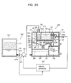
- FIGS. 20 to 25 show a waste liquid regeneration apparatus and a waste liquid regeneration method for a printer according to an eleventh embodiment of the present invention, and wherein FIG. 20 is a schematic sectional view of the waste liquid regeneration apparatus as viewed in a sideward direction of a waste liquid reserving vessel; FIG. 21 is a schematic view illustrating a waste liquid regeneration principle of the waste liquid regeneration apparatus; and FIGS. 22 to 24 are schematic sectional views illustrating a waste liquid regeneration process of the waste liquid regeneration apparatus.
- the waste liquid regeneration apparatus 140 for a printer includes a waste liquid tank 180, a regeneration tank 175, a water recovering water tank 190, a regenerated liquid tank 170, a recovered water tank 191 and a filter tank 201 provided integrally in an armoring case 141.
- the waste liquid tank (first chamber) 180, regeneration tank (second tank) 175 and water recovering water tank (third chamber) 190 are formed as a single vessel 145 and are provided at an upper portion of a central portion in the armoring case 141.
- a space defined by vertical insulating walls 102 and 119 is provided at an upper portion in the vessel 145, and two metal electrode plates 130a and 130b are provided horizontally or substantially horizontally in an upwardly and downwardly spaced relationship from each other in the space.
- a space partitioned by the insulating walls 102 and 119 and the lower side metal electrode plate 130a forms the regeneration tank 175, and a space on the outer side of the regeneration tank 175 serves as the waste liquid tank 180.
- a waste liquid loading pipe 142 for loading waste liquid 111 into the waste liquid tank 180 is provided above the waste liquid tank 180.
- a bottom portion of the vessel 145 is formed in a funnel shape, and a space surrounded by the conical face of the funnel serves as the water recovering water tank 190.
- the metal electrode plates 130a and 130b are connected to a high voltage power supply not shown such that high voltages are applied thereto.
- a potential difference is provided between the two metal electrode plates 130a and 130b, and a higher voltage than that applied to the metal electrode plate 130a nearer to the water recovering water tank 190 is applied to the metal electrode plate 130b farther from the water recovering water tank 190.
- a grounding electrode 18 is connected to the water recovering water tank 190 so as to energize regenerated water 109 in the water recovering water tank 190.
- the water 109 and the ink pigment 188 are separated fully from the cleaning liquid 162, and the water 109 agglomerates into a mass and settles toward the water recovering water tank 190 by the gravity as seen in X13 of FIG. 21. Further, the ink pigment 188 of the + charges is attracted to the water 109 in the water recovering water tank 190 serving as the - pole and agglomerates into a film in the proximity of the interface of the water 109.
- the regenerated liquid tank 170 is provided sidewardly adjacent the regeneration tank 175, and the regenerated liquid tank 170 and the regeneration tank 175 are communicated with each other through a regenerated liquid recovering pipe 172.
- the position of the liquid surface of the regeneration tank 175 rises by an amount corresponding to the amount of the waste liquid 111 supplied into the waste liquid tank 180, and as a result of the liquid surface position, the clean cleaning liquid (regenerated cleaning liquid) 162 overflows from the regeneration tank 175 and is recovered into the regenerated liquid tank 170.
- the recovered water tank 191 is provided below the water recovering water tank 190.
- the water recovering water tank 190 and the recovered water tank 191 are communicated with each other through a recovering pipe 193.
- An on-off valve 195 is provided for the recovering pipe 193 and operates in response to detection signals of two upper and lower water interface detection sensors 211 and 212 provided in the vessel 145. In particular, if the water interface detection sensor 211 on the upper side detects the interface of the regenerated water 109, then the on-off valve 195 is opened, but if the water interface detection sensor 212 on the lower side detects the interface of the regenerated water 109, then the on-off valve 195 is closed. Consequently, the interface of the regenerated water 109 is held between the water interface detection sensors 211 and 212, and the region between the water interface detection sensors 211 and 212 serves as a substantial boundary between the waste liquid tank 180 and the water recovering water tank 190.
- the filter tank 201 is provided immediately below the water recovering water tank 190.
- An on-off valve 192 is provided between an end of the bottom of the water recovering water tank 190 and the filter tank 201.
- the on-off valve 192 is used to open or close the water tank 190, and is driven to open or close by an opening-closing driving motor 194 and is normally closed.
- a filter 200 is disposed horizontally or substantially horizontally in the filter tank 201.
- the on-off valve 192 is opened so that the ink pigment 188 is dropped into the filter tank 201 together with the water 109 and the waste liquid 111 in the vessel 145.
- the water 109 and the waste liquid 111 pass through the filter 200 and are recovered at a lower portion in the filter tank 201 while the ink pigment 188 is caught by the filter 200 and recovered.
- a pipe 223 is connected to the bottom of the regenerated liquid tank 170, and an on-off valve 227 is provided at an entrance of the pipe 223.
- the pipe 223 is connected to the bottom of the recovered water tank 191, and an on-off valve 222 is provided at another entrance of the pipe 223.
- a pipe 220 is connected to a lower portion of the filter tank 201, and an on-off valve 221 is interposed at an entrance of the pipe 220.
- the on-off valves 227, 222 and 221 are normally closed, but are opened when the regenerated cleaning liquid 162, regenerated water 109 and waste liquid 111 recovered in the tanks 170, 191 and 201 are to be discharged.
- the pipe 223 connected to the regenerated liquid tank 170 and the recovered water tank 191 is branched into two pipes 224 and 226, and on-off valves 228 and 225 are interposed in the pipes 224 and 226 in the proximity of the branching portion.
- the on-off valve 225 is provided to allow the regenerated cleaning liquid 162 and the water 109 to be returned to the waste liquid tank 180 while the on-off valve 228 is provided to allow the regenerated cleaning liquid 162 and the water 109 to be fed to a blanket cleaning apparatus.
- the pipes 220, 223 and 226 function as returning flow paths for returning the regenerated liquid 162, regenerated water 109 and waste liquid 111 to the waste liquid tank 180.
- liquid face detection sensors are provided individually for the tanks so that an overflow or a level drop can be prevented.
- a waste liquid level sensor 210 for detecting the top face of the waste liquid 111 is provided in the waste liquid tank 180
- a liquid face detection sensor 213 for detecting the top face of the regenerated cleaning liquid 162 is provided in the regeneration tank 175 while a liquid face detection sensor 214 for detecting the top face of the recovered water 109 is provided in the recovered water tank 191.
- the ink pigment 188 may possibly come into contact with the application electrode 130a to cause electrical leak, and therefore, for example, after a work for one day comes to an end (or after predetermined time passes after starting of the regeneration), it is necessary to stop the regeneration and dispose of the ink pigment 188.
- the regenerated liquid 162 regenerated and reserved in the regenerated liquid tank 170 and the water 109 recovered in the recovered water tank 191 are sent to and used by the blanket cleaning apparatus (not shown) for cleaning of a blanket by opening the on-off valves 227 and 222 and the on-off valve 228, respectively. Thereafter, the regenerated liquid 162 and the water 109 are recovered as the waste liquid 111 and sent into the waste liquid tank 180 and then recycled. It is to be noted that only one of the regenerated liquid 162 and the water 109 may otherwise be used by itself. To this end, only a required one or ones of the valves may be opened.
- Disposal of the ink pigment 188 described above can be performed in the followingmanner. Inparticular, after the ink pigment 188 is separated up to the state of FIG. 22, it is recovered into the filter tank 201. If the on-off valve 192 provided at a lower portion of the water tank 190 is opened, then the water 109 in the water tank 190 and the ink pigment film 188 separated on the surface of the water 109 as well as the waste liquid 111 in the waste liquid tank 180 and the waste liquid 111 and the regenerated liquid 162 in the regeneration tank 175 drop into the filter tank 201 provided below the water tank 190.
- the ink pigment film 188 Since the ink pigment film 188 is discharged suddenly together with the waste liquid 111, regenerated liquid 162 and water 109, also the ink pigment 188 which has a high viscosity is dropped simultaneously by the water flow.
- the waste liquid tank 180, regeneration tank 175 and water tank 190 are placed in an empty state as seen in FIG. 23.
- the regenerated cleaning liquid 162 is reserved in the regenerated liquid tank 170 and the water 109 is reserved in the recovered water tank 191 as well.
- the dropped water 109, waste liquid 111 and regenerated cleaning liquid 162 are reserved as the mixed waste liquid 111 in the filter tank 201, the waste liquid 111 is regenerated again.
- the filter 200 by which the ink pigment 188 is collected is used for similar recovery by several times until a predetermined filter collection capacity thereof is exhausted, and thereafter, it is drawn out to the outside and disposed of while a new filter is set in exchange.
- the supply of the waste liquid 111 and of the water 109 to the regeneration tanks 180 and 175 is performed until the top face of the water 109 comes to a position between the water interface detection sensors 211 and 212 whereas the supply of the regenerated cleaning liquid 162 is performed until a state in which the voltages can be applied to the electrodes is reached (until a state wherein the regenerated cleaning liquid 162 is stored to the level of the application electrodes 130a and 130b). In this state, since only the clean water 109 and regenerated cleaning liquid 162 are present in the regeneration tank 175, the inside of the regeneration tank 175 is free from contamination.
- the waste liquid 111 reserved in the filter tank 201 is regenerated.
- the voltages are applied to the electrodes 130a and 130b, and the on-off valve 221 for the filter tank 201 is opened to supply the waste liquid 111 from the waste liquid loading pipe 142 into the waste liquid tank 180 through the pipe 220.
- waste liquid 111 When the waste liquid 111 is supplied in this manner, it is separated into the ink pigment 188, regenerated cleaning liquid 162 and water 109 simultaneously, and consequently, the waste liquid 111 is regenerated by the action and process described above. Then, after the waste liquid in the filter tank 201 is all supplied, waste liquid after used for cleaning of the blanket is supplied and regenerated as in an original case.
- the cleaning waste liquid 111 is separated into cleaning liquid 162, regenerated water 109 and ink pigment 188, and the ink pigment 188 is recovered by the filter 200 and disposed of while the regenerated water 109 and the regenerated cleaning liquid 162 are reused.
- the waste liquid regeneration apparatus of the present embodiment in the system wherein the three components of the ink pigment 188, insulating cleaning liquid 162 and conductive water 109 exist in a mixed state, the three components can be separated from one another by means of a single apparatus without providing the grounding electrode in the inside of the vessel while utilizing the conductivity of the water. Besides, such separation can be performed efficiently in comparatively short time. Also recovery and removal of the ink pigment 188 and reuse of the water 109 and the regenerated liquid 162 can be performed readily and smoothly, resulting in significant improvement in practical use.
- FIGS. 25(a) and 25(b) are views showing a water recovering water tank of a waste liquid regeneration apparatus for a printer according to the twelfth embodiment of the present invention, and wherein FIG. 25 (a) is a top plan view of the water recovering water tank and FIG. 25 (b) is a schematic sectional view as viewed in a sideward direction of the water recovering water tank.
- the present embodiment is characterized in the water recovering water tank 90, and the other part thereof is configured similar to that of the eleventh embodiment.
- the present invention is that a configuration which allows the separated ink pigment 188 to be disposed of to the outside is provided. To this end, it is necessary to allow the ink pigment 188 separated on the surface of the water 109 in the water tank 190 to drop smoothly and thoroughly without adhering to the inner face of the water tank 190. Therefore, in the present embodiment, the water recovering water tank 190 is configured in the following manner.
- the water recovering water tank 190 is formed in a funnel shape, and a soil release process layer 116 is applied to the inner face of a water tank body 115.
- the soil release process may be a resin work, for example, of PTFE or a process which makes use of tiles, pottery or the like.
- the ink pigment film 188 separated on the surface of the water in the water tank 190 is discharged smoothly from an outlet 189 at a lower end of the water tank 190 together with the water 109 and so forth. Accordingly, the separated ink pigment 188 can be disposed of to the outside with certainty.
- the metal electrode plates 130a and 130b are configured so as to allow the cleaning liquid 162 to flow therethrough, when no voltage is applied to them, also the ink pigment 188 mixed in the cleaning liquid 162 can pass through the metal electrode plates 130a and 130b.
- the ink pigment 188 having the + charges cannot pass through the metal electrode plates 130a and 130b readily.
- the metal electrode plates 130a and 130b function as filters for preventing the ink pigment 188 from flowing into the inside of the regeneration tank 175, particularly into an upper portion of the regeneration tank 175, together with the cleaning liquid 162.
- FIG. 26 is a view schematically showing a cross section of the waste liquid regeneration apparatus for a printer according to the present embodiment as viewed in a sideward direction together with a waste liquid supplying system and a controlling system.
- the waste liquid regeneration apparatus 240 for a printer according to the present embodiment has a similar basic configuration beginning with a waste liquid regeneration principle to that of the waste liquid regeneration apparatus according to the eleventh embodiment described hereinabove with reference to FIG. 21, and in the figure, common elements are denoted by like reference characters.
- the waste liquid supplying apparatus 340 is an apparatus for supplying waste liquid 111 to the waste liquid regeneration apparatus 340 and includes a waste liquid recovering tank 230 for storing waste liquid 111 recovered from the printer, a pump 232 for pressure feeding the waste liquid 111 from the waste liquid recovering tank 230 to the waste liquid loading pipe 142 of the waste liquid regeneration apparatus 240, and a control apparatus 234 for controlling operation of the pump 232.
- waste liquid supplying method As an operation method (waste liquid supplying method) of the pump 232 by the control apparatus 234, a continuous supplying method for continuously supplying the waste liquid 111 at a fixed speed and an intermittent supplying method for alternately repeating supplying and stopping of the waste liquid 111 are available.
- the waste liquid supplying apparatus 340 uses the intermittent supplying method as a basic method for the operation of the pump 232. However, the operation method can be arbitrarily changed over between the continuous supplying method and the intermittent supplying method by means of a changeover switch 236 connected to the control apparatus 234.
- control apparatus 234 not only the supplying speed V0 of the waste liquid 111 in the continuous supplying method but also the supplying speed V1, supplying time T1 and stopping time T2 of the waste liquid 111 in the intermittent supplying method can be adjusted arbitrarily from the outside so that optimum values based on a result of an experiment or the like can be set to them.
- the concentration of ink pigment contained in the regenerated cleaning liquid 162 can be suppressed lower with the intermittent supplying method than with the continuous supplying method.
- the cleaning liquid 162 in the waste liquid tank 180 is normally turbid with the ink pigment 188, but where the intermittent supplying method is used, the ink pigment 188 in the waste liquid tank 180 agglomerates, during stopping of the supply of the waste liquid 111, to the interface of the regenerated water 109 by electrophoresis by an action of the electric field and the purity of the cleaning liquid 162 in the waste liquid tank 180 gradually rises.
- the ink pigment 188 is prevented from flowing into the regeneration tank 175 passing through the metal electrode plates 130a and 130b together with the cleaning liquid 162.
- the continuous supplying method it is necessary to supply the waste liquid 111 slowly at a low speed so that the ink pigment 188 may not be pushed out through the metal electrode plates 130a and 130b to the regeneration tank 175.
- the intermittent supplying method for a period of time until the ink pigment 188 diffuses in the waste liquid tank 180 as a result of the supply of the waste liquid 111 to lower the purity of the cleaning liquid 162 in the waste liquid tank 180, the waste liquid 111 can be supplied at a high supplying speed. Accordingly, with the intermittent supplying method, a high processing capacity can be obtained as a whole when compared with the continuous supplying method, and the regeneration processing time can be reduced while the purity of the cleaning liquid 162 is maintained.
- waste liquid 111 which contains water as a major component is sometimes supplied from the waste liquid recovering tank 230, and in such an instance, even if the waste liquid 111 is supplied continuously, the purity of the cleaning liquid 162 in the waste liquid tank 180 does not drop. Further, even if the waste liquid 111 is supplied at a high supplying speed, the possibility that the ink pigment 188 may flow into the regeneration tank 175 passing through the metal electrode plates 130a and 130b together with the cleaning liquid 162 is low.
- the waste liquid 111 contains the water 109 as a maj or component
- the purity of the cleaning liquid 162 can be maintained. Therefore, it is not necessary to use the intermittent supplying method to supply the waste liquid 111, but rather, where the continuous supplying method is used and the supplying speed is raised to supply the waste liquid 111, the regeneration processing time can be reduced when compared with that where the intermittent supplying method is used for the supply.
- the operation method of the pump 232 can be changed over from the intermittent supplying method to the continuous supplying method by means of the changeover switch 236 to raise the processing capacity. Consequently, the regeneration processing time can be further reduced as a whole.
- waste liquid regeneration apparatus of the present embodiment adopts the following configuration as a further modification to the waste liquid regeneration apparatus of the eleventh embodiment.
- the on-off valve 192 is opened to recover the ink pigment 188 into the filter tank 201, there is the possibility that not a small amount of the ink pigment 188 may remain adhering to a wall of the vessel 145.
- the waste liquid regeneration apparatus 240 is to be restarted, fresh water 109 and cleaning liquid 162 are loaded into the waste liquid tank 180 from the waste liquid loading pipe 142 first and the water 109 is filled into the water tank 190, and the waste liquid regeneration apparatus 240 is restarted in a state wherein the cleaning liquid 162 is filled in the waste liquid tank 180 and the regeneration tank 175.
- the location of the water interface detection sensor 212 on the lower side is set to a position higher than the conical face of the funnel formed on the bottom of the vessel 145. This is a countermeasure for making it difficult for the film of the ink pigment 188 agglomerating on the interface of the water 109 to adhere to the conical face of the funnel.
- shower nozzles 196 are mounted on a surrounding side wall of the waste liquid tank 180.
- the shower nozzles 196 are adapted to jet a shower toward the conical face of the funnel along the wall face of the waste liquid tank 180 so that the ink pigment 188 adhering to the conical face of the funnel may be compulsorily washed away by the shower.
- a signal from the sensor 237 provided at an exit of the waste liquid recovering tank 230 is inputted to the control apparatus 234'.
- the sensor 237 includes a light emitting/receiving element 237a and a reflecting plate 237b and detects a light passing state through the waste liquid 111 discharged from the waste liquid recovering tank 230.
- the element 237a can detect reflected light from the reflecting plate 237b, but where the waste liquid 111 contains the cleaning liquid 162 in which the ink pigment 188 is mixed as a major component, since the waste liquid 111 is almost black, the element 237a cannot detect reflected light.
- a signal from the sensor 236 provided for the regenerated liquid recovering pipe 172 is inputted to the control apparatus 234'.
- the sensor 236 includes a light emitting/receiving element 236a and a reflecting plate 236b, and the element 236a and the reflecting plate 236b are disposed on opposing wall faces of the regenerated liquid recovering pipe 172.
- the changeover switch 236 detects the intensity of reflected light from the reflecting plate 236b received by the element 236a, that is, the transmission factor of the regenerated cleaning liquid 162 flowing in the regenerated liquid recovering pipe 172, and outputs the transmission factor to the control apparatus 234'.
- the control apparatus 234' collates the detected transmission factor of the regenerated cleaning liquid 162 with a calibration curve to determine the concentration of the ink pigment 188 in the regenerated cleaning liquid 162.
- the calibration line is determined by an experiment and represents a relationship between the transmission factor and the ink pigment concentration.
- the control apparatus 234' compares the resulting ink pigment concentration with an upper limit value of a predetermined control range, and if the ink pigment concentration exceeds the upper limit value, then the control apparatus 234' increases the stopping time T2 in accordance with the difference between them.
- the present invention is not limited to the specific embodiments but can be carried out in various modified forms without departing from the spirit and scope of the present invention.
- a greater number of metal electrode plates 30 may be installed in the vessel 2.
- the metal electrode plates 30 are not limited to those of the wire mesh type.
- the waste liquid supplying method is changed over between the intermittent supplying method and the continuous supplying method
- the pump 232 may otherwise be operated normally in accordance with the intermittent supplying method.
- the regeneration processing time can be reduced while maintaining the purity of the regenerated cleaning liquid when compared with an alternative case wherein the continuous supplying system is normally used.
- the automatic changeover control between the intermittent supplying method and the continuous supplying method and the feedback control of the stopping time T2 in the intermittent supplying method are used, only one of the controls may otherwise be used.
- the control object of the feed back control may include not only the stopping time T2 of waste liquid supply but also the supplying speed V1 or the supplying time T1 of waste liquid supply, may include a plurality of ones of them.
Landscapes
- Chemical & Material Sciences (AREA)
- Chemical Kinetics & Catalysis (AREA)
- Life Sciences & Earth Sciences (AREA)
- Hydrology & Water Resources (AREA)
- Engineering & Computer Science (AREA)
- Environmental & Geological Engineering (AREA)
- Water Supply & Treatment (AREA)
- Organic Chemistry (AREA)
- Electrochemistry (AREA)
- General Chemical & Material Sciences (AREA)
- Physics & Mathematics (AREA)
- Thermal Sciences (AREA)
- Health & Medical Sciences (AREA)
- Analytical Chemistry (AREA)
- Molecular Biology (AREA)
- Inking, Control Or Cleaning Of Printing Machines (AREA)
- Water Treatment By Electricity Or Magnetism (AREA)
- Ink Jet (AREA)
- Electrostatic Separation (AREA)
Applications Claiming Priority (3)
| Application Number | Priority Date | Filing Date | Title |
|---|---|---|---|
| JP2002380374 | 2002-12-27 | ||
| JP2002380374A JP4233866B2 (ja) | 2002-12-27 | 2002-12-27 | 印刷機の廃液再生装置 |
| PCT/JP2003/003359 WO2004060816A1 (fr) | 2002-12-27 | 2003-03-19 | Regenerateur de residu liquide de machine d'impression et procede de regeneration de residu liquide |
Publications (2)
| Publication Number | Publication Date |
|---|---|
| EP1586540A1 true EP1586540A1 (fr) | 2005-10-19 |
| EP1586540A4 EP1586540A4 (fr) | 2006-02-08 |
Family
ID=32708434
Family Applications (1)
| Application Number | Title | Priority Date | Filing Date |
|---|---|---|---|
| EP03710437A Withdrawn EP1586540A4 (fr) | 2002-12-27 | 2003-03-19 | Regenerateur de residu liquide de machine d'impression et procede de regeneration de residu liquide |
Country Status (4)
| Country | Link |
|---|---|
| US (1) | US7472651B2 (fr) |
| EP (1) | EP1586540A4 (fr) |
| JP (1) | JP4233866B2 (fr) |
| WO (1) | WO2004060816A1 (fr) |
Families Citing this family (7)
| Publication number | Priority date | Publication date | Assignee | Title |
|---|---|---|---|---|
| JP4843265B2 (ja) * | 2005-06-15 | 2011-12-21 | 三菱重工印刷紙工機械株式会社 | 廃液再生装置 |
| US20070012208A1 (en) * | 2005-07-13 | 2007-01-18 | Byungwoo Cho | Offset printing system |
| JP4480166B2 (ja) * | 2005-08-11 | 2010-06-16 | キヤノン株式会社 | 液体塗布装置およびインクジェット記録装置 |
| US8538317B2 (en) * | 2008-11-07 | 2013-09-17 | Kabushiki Kaisha Toshiba | Image elimination apparatus, image eliminating method and image forming apparatus |
| CN103466760B (zh) * | 2013-09-27 | 2015-12-23 | 上海原青环保工程有限公司 | 电磁式泥水分离塔及电磁式泥水分离方法 |
| WO2018006141A1 (fr) * | 2016-07-04 | 2018-01-11 | Adriano Duvoisin Charles | Système et procédé pour l'application d'énergie électromagnétique à des contenus conditionnés et équipement correspondant |
| CN111359962B (zh) * | 2020-03-27 | 2022-03-18 | 苏州无为环境科技有限公司 | 一种电絮凝极板自动清洗和更换系统 |
Citations (6)
| Publication number | Priority date | Publication date | Assignee | Title |
|---|---|---|---|---|
| US4288303A (en) * | 1978-10-20 | 1981-09-08 | Environmental Sciences Associates, Inc. | Electrochemical processing system |
| JPS6430691A (en) * | 1987-07-27 | 1989-02-01 | Sanshu Kaken Kogyo Kk | Method and device for water treatment |
| RU2152359C1 (ru) * | 1999-01-20 | 2000-07-10 | Товарищество с ограниченной ответственностью "Имкомтех" | Устройство для очистки и обеззараживания воды высоковольтными электрическими разрядами |
| US6267871B1 (en) * | 1999-02-10 | 2001-07-31 | Edward C. Weakly | Apparatus and process for recovering metals from aqueous solutions |
| JP2001328243A (ja) * | 2000-05-19 | 2001-11-27 | Mitsubishi Heavy Ind Ltd | 印刷機の廃液再生装置 |
| JP2002023583A (ja) * | 2000-07-10 | 2002-01-23 | Mitsubishi Heavy Ind Ltd | 液体トナーの再生装置及び再生方法 |
Family Cites Families (10)
| Publication number | Priority date | Publication date | Assignee | Title |
|---|---|---|---|---|
| US1774778A (en) * | 1926-11-26 | 1930-09-02 | Wood Newspaper Mach Corp | Inking system for printing presses |
| US3926114A (en) * | 1967-06-30 | 1975-12-16 | Walter E S Matuschke | Rotary lithographic printing press with ink and dampening fluid separator |
| GB1308470A (en) | 1969-08-25 | 1973-02-21 | North American Rockwell | Method and apparatus for removing contaminants from liquids |
| JPS5310440A (en) | 1976-07-15 | 1978-01-30 | Ricoh Co Ltd | Liquid cleaning system |
| US4527479A (en) * | 1981-07-31 | 1985-07-09 | Dahlgren Harold P | Ink removal, circulating and distributing system |
| DE3580908D1 (de) * | 1984-12-26 | 1991-01-24 | Dainippon Printing Co Ltd | Tiefdrucksystem. |
| JPH0436236Y2 (fr) | 1987-08-14 | 1992-08-26 | ||
| JP3637262B2 (ja) | 2000-05-12 | 2005-04-13 | 三菱重工業株式会社 | 印刷機の廃液再生装置 |
| JP3586630B2 (ja) | 2000-06-20 | 2004-11-10 | 三菱重工業株式会社 | 印刷機の廃液再生装置及び廃液再生方法 |
| JP3586656B2 (ja) | 2001-04-03 | 2004-11-10 | 三菱重工業株式会社 | 印刷機の廃液再生装置および廃液再生方法 |
-
2002
- 2002-12-27 JP JP2002380374A patent/JP4233866B2/ja not_active Expired - Fee Related
-
2003
- 2003-03-19 EP EP03710437A patent/EP1586540A4/fr not_active Withdrawn
- 2003-03-19 WO PCT/JP2003/003359 patent/WO2004060816A1/fr active Application Filing
- 2003-03-19 US US10/537,589 patent/US7472651B2/en not_active Expired - Fee Related
Patent Citations (6)
| Publication number | Priority date | Publication date | Assignee | Title |
|---|---|---|---|---|
| US4288303A (en) * | 1978-10-20 | 1981-09-08 | Environmental Sciences Associates, Inc. | Electrochemical processing system |
| JPS6430691A (en) * | 1987-07-27 | 1989-02-01 | Sanshu Kaken Kogyo Kk | Method and device for water treatment |
| RU2152359C1 (ru) * | 1999-01-20 | 2000-07-10 | Товарищество с ограниченной ответственностью "Имкомтех" | Устройство для очистки и обеззараживания воды высоковольтными электрическими разрядами |
| US6267871B1 (en) * | 1999-02-10 | 2001-07-31 | Edward C. Weakly | Apparatus and process for recovering metals from aqueous solutions |
| JP2001328243A (ja) * | 2000-05-19 | 2001-11-27 | Mitsubishi Heavy Ind Ltd | 印刷機の廃液再生装置 |
| JP2002023583A (ja) * | 2000-07-10 | 2002-01-23 | Mitsubishi Heavy Ind Ltd | 液体トナーの再生装置及び再生方法 |
Non-Patent Citations (5)
| Title |
|---|
| KIM T-H ET AL: "Decolorization of disperse and reactive dyes by continuous electrocoagulation process" DESALINATION, ELSEVIER, AMSTERDAM, NL, vol. 150, no. 2, 1 November 2002 (2002-11-01), pages 165-175, XP004454552 ISSN: 0011-9164 * |
| PATENT ABSTRACTS OF JAPAN vol. 013, no. 211 (C-597), 17 May 1989 (1989-05-17) -& JP 01 030691 A (SANSHU KAKEN KOGYO KK), 1 February 1989 (1989-02-01) * |
| PATENT ABSTRACTS OF JAPAN vol. 2002, no. 03, 3 April 2002 (2002-04-03) -& JP 2001 328243 A (MITSUBISHI HEAVY IND LTD), 27 November 2001 (2001-11-27) * |
| PATENT ABSTRACTS OF JAPAN vol. 2002, no. 05, 3 May 2002 (2002-05-03) -& JP 2002 023583 A (MITSUBISHI HEAVY IND LTD), 23 January 2002 (2002-01-23) * |
| See also references of WO2004060816A1 * |
Also Published As
| Publication number | Publication date |
|---|---|
| US20060144268A1 (en) | 2006-07-06 |
| US7472651B2 (en) | 2009-01-06 |
| WO2004060816A1 (fr) | 2004-07-22 |
| JP2004209350A (ja) | 2004-07-29 |
| JP4233866B2 (ja) | 2009-03-04 |
| EP1586540A4 (fr) | 2006-02-08 |
Similar Documents
| Publication | Publication Date | Title |
|---|---|---|
| US5923930A (en) | Apparatus for controlling density of liquid developing solution and apparatus for forming images | |
| EP2834710B1 (fr) | Développeur d'encre pour électrophotographie liquide | |
| US7472651B2 (en) | Waste liquid regenerator of printing machine | |
| EP0875805B1 (fr) | Appareil de transfert de masse | |
| JP5389252B2 (ja) | 液体トナー用固形分分離装置 | |
| US5514269A (en) | Dual separator purification system | |
| JP3981489B2 (ja) | 湿式画像形成装置および湿式画像形成方法 | |
| US5942095A (en) | Method of continuous purification of liquid toner in an electrostatic printing system | |
| KR101682957B1 (ko) | 화상 형성 장치용 토너 리사이클링 장치 | |
| JP3586656B2 (ja) | 印刷機の廃液再生装置および廃液再生方法 | |
| JP3586630B2 (ja) | 印刷機の廃液再生装置及び廃液再生方法 | |
| JP2017040771A (ja) | 分離装置及び画像形成装置 | |
| JP3697123B2 (ja) | 印刷機の廃液再生装置 | |
| JP2003270957A (ja) | キャリア液リサイクル装置 | |
| EP3841435B1 (fr) | Filtration de support liquide | |
| JP3993534B2 (ja) | 印刷機の洗浄廃液再生装置及び再生方法 | |
| JP4365697B2 (ja) | 印刷機の廃液再生装置及び廃液再生方法 | |
| US7756449B2 (en) | Electrophotographic printing apparatus and methods in which carrier medium is extracted from unused ink | |
| KR100573661B1 (ko) | 폐현상제 클리닝시스템 및 그것을 구비한 화상형성장치 | |
| JP6677002B2 (ja) | 液体現像剤供給装置、現像装置及び画像形成装置 | |
| WO1996007124A1 (fr) | Systeme de purification comportant des purificateurs electrophoretiques et a filtre particulaire | |
| JP2007222710A (ja) | 印刷機の廃液再生方法および廃液再生装置 | |
| JP2007160177A (ja) | 印刷機の廃液再生方法及び印刷機の廃液再生用エマルション処理剤 | |
| KR100574024B1 (ko) | 화상형성장치의 폐 현상제 처리장치 및 처리방법 | |
| JP3702130B2 (ja) | 印刷機の廃液再生装置 |
Legal Events
| Date | Code | Title | Description |
|---|---|---|---|
| PUAI | Public reference made under article 153(3) epc to a published international application that has entered the european phase |
Free format text: ORIGINAL CODE: 0009012 |
|
| 17P | Request for examination filed |
Effective date: 20050617 |
|
| AK | Designated contracting states |
Kind code of ref document: A1 Designated state(s): AT BE BG CH CY CZ DE DK EE ES FI FR GB GR HU IE IT LI LU MC NL PT RO SE SI SK TR |
|
| A4 | Supplementary search report drawn up and despatched |
Effective date: 20051228 |
|
| RIC1 | Information provided on ipc code assigned before grant |
Ipc: C02F 1/469 20060101ALI20051221BHEP Ipc: C02F 1/463 20060101ALI20051221BHEP Ipc: C02F 1/48 20060101AFI20040723BHEP Ipc: B41F 35/00 20060101ALI20051221BHEP |
|
| RBV | Designated contracting states (corrected) |
Designated state(s): DE FR GB IT |
|
| GRAP | Despatch of communication of intention to grant a patent |
Free format text: ORIGINAL CODE: EPIDOSNIGR1 |
|
| RTI1 | Title (correction) |
Free format text: WASTE LIQUID REGENERATION APPARATUS FOR A PRINTER |
|
| GRAC | Information related to communication of intention to grant a patent modified |
Free format text: ORIGINAL CODE: EPIDOSCIGR1 |
|
| STAA | Information on the status of an ep patent application or granted ep patent |
Free format text: STATUS: THE APPLICATION IS DEEMED TO BE WITHDRAWN |
|
| 18D | Application deemed to be withdrawn |
Effective date: 20100615 |