EP1585344A2 - Dispositif d'affichage de type projecteur - Google Patents
Dispositif d'affichage de type projecteur Download PDFInfo
- Publication number
- EP1585344A2 EP1585344A2 EP05014061A EP05014061A EP1585344A2 EP 1585344 A2 EP1585344 A2 EP 1585344A2 EP 05014061 A EP05014061 A EP 05014061A EP 05014061 A EP05014061 A EP 05014061A EP 1585344 A2 EP1585344 A2 EP 1585344A2
- Authority
- EP
- European Patent Office
- Prior art keywords
- polarization
- light
- illumination light
- reflection
- image
- Prior art date
- Legal status (The legal status is an assumption and is not a legal conclusion. Google has not performed a legal analysis and makes no representation as to the accuracy of the status listed.)
- Granted
Links
- 230000010287 polarization Effects 0.000 claims abstract description 343
- 230000003287 optical effect Effects 0.000 claims abstract description 237
- 238000000926 separation method Methods 0.000 claims abstract description 97
- 238000005286 illumination Methods 0.000 claims description 192
- 239000004973 liquid crystal related substance Substances 0.000 abstract description 86
- 239000000463 material Substances 0.000 description 29
- 239000011521 glass Substances 0.000 description 27
- 230000035882 stress Effects 0.000 description 20
- 230000008646 thermal stress Effects 0.000 description 12
- 230000002194 synthesizing effect Effects 0.000 description 9
- 238000010030 laminating Methods 0.000 description 8
- 238000006243 chemical reaction Methods 0.000 description 6
- 238000001514 detection method Methods 0.000 description 6
- 229910052724 xenon Inorganic materials 0.000 description 6
- FHNFHKCVQCLJFQ-UHFFFAOYSA-N xenon atom Chemical compound [Xe] FHNFHKCVQCLJFQ-UHFFFAOYSA-N 0.000 description 6
- 230000009467 reduction Effects 0.000 description 5
- 230000005540 biological transmission Effects 0.000 description 4
- 239000005357 flat glass Substances 0.000 description 4
- 230000005484 gravity Effects 0.000 description 4
- 230000031700 light absorption Effects 0.000 description 4
- 238000002834 transmittance Methods 0.000 description 4
- 230000000694 effects Effects 0.000 description 3
- 230000010354 integration Effects 0.000 description 3
- 230000032683 aging Effects 0.000 description 2
- 230000015572 biosynthetic process Effects 0.000 description 2
- 230000006866 deterioration Effects 0.000 description 2
- 239000002699 waste material Substances 0.000 description 2
- 230000008859 change Effects 0.000 description 1
- 239000011248 coating agent Substances 0.000 description 1
- 238000000576 coating method Methods 0.000 description 1
- 230000007547 defect Effects 0.000 description 1
- 230000001419 dependent effect Effects 0.000 description 1
- 230000004069 differentiation Effects 0.000 description 1
- 238000006073 displacement reaction Methods 0.000 description 1
- 238000011156 evaluation Methods 0.000 description 1
- 230000004907 flux Effects 0.000 description 1
- 238000004519 manufacturing process Methods 0.000 description 1
- 230000004048 modification Effects 0.000 description 1
- 238000012986 modification Methods 0.000 description 1
- 238000005498 polishing Methods 0.000 description 1
Images


Classifications
-
- G—PHYSICS
- G02—OPTICS
- G02B—OPTICAL ELEMENTS, SYSTEMS OR APPARATUS
- G02B27/00—Optical systems or apparatus not provided for by any of the groups G02B1/00 - G02B26/00, G02B30/00
- G02B27/10—Beam splitting or combining systems
- G02B27/14—Beam splitting or combining systems operating by reflection only
- G02B27/145—Beam splitting or combining systems operating by reflection only having sequential partially reflecting surfaces
-
- G—PHYSICS
- G02—OPTICS
- G02B—OPTICAL ELEMENTS, SYSTEMS OR APPARATUS
- G02B27/00—Optical systems or apparatus not provided for by any of the groups G02B1/00 - G02B26/00, G02B30/00
- G02B27/10—Beam splitting or combining systems
- G02B27/1006—Beam splitting or combining systems for splitting or combining different wavelengths
- G02B27/102—Beam splitting or combining systems for splitting or combining different wavelengths for generating a colour image from monochromatic image signal sources
- G02B27/1026—Beam splitting or combining systems for splitting or combining different wavelengths for generating a colour image from monochromatic image signal sources for use with reflective spatial light modulators
-
- G—PHYSICS
- G02—OPTICS
- G02B—OPTICAL ELEMENTS, SYSTEMS OR APPARATUS
- G02B27/00—Optical systems or apparatus not provided for by any of the groups G02B1/00 - G02B26/00, G02B30/00
- G02B27/28—Optical systems or apparatus not provided for by any of the groups G02B1/00 - G02B26/00, G02B30/00 for polarising
- G02B27/283—Optical systems or apparatus not provided for by any of the groups G02B1/00 - G02B26/00, G02B30/00 for polarising used for beam splitting or combining
-
- H—ELECTRICITY
- H04—ELECTRIC COMMUNICATION TECHNIQUE
- H04N—PICTORIAL COMMUNICATION, e.g. TELEVISION
- H04N9/00—Details of colour television systems
- H04N9/12—Picture reproducers
- H04N9/31—Projection devices for colour picture display, e.g. using electronic spatial light modulators [ESLM]
- H04N9/3102—Projection devices for colour picture display, e.g. using electronic spatial light modulators [ESLM] using two-dimensional electronic spatial light modulators
- H04N9/3105—Projection devices for colour picture display, e.g. using electronic spatial light modulators [ESLM] using two-dimensional electronic spatial light modulators for displaying all colours simultaneously, e.g. by using two or more electronic spatial light modulators
-
- H—ELECTRICITY
- H04—ELECTRIC COMMUNICATION TECHNIQUE
- H04N—PICTORIAL COMMUNICATION, e.g. TELEVISION
- H04N9/00—Details of colour television systems
- H04N9/12—Picture reproducers
- H04N9/31—Projection devices for colour picture display, e.g. using electronic spatial light modulators [ESLM]
- H04N9/3141—Constructional details thereof
- H04N9/315—Modulator illumination systems
- H04N9/3167—Modulator illumination systems for polarizing the light beam
-
- H—ELECTRICITY
- H04—ELECTRIC COMMUNICATION TECHNIQUE
- H04N—PICTORIAL COMMUNICATION, e.g. TELEVISION
- H04N5/00—Details of television systems
- H04N5/74—Projection arrangements for image reproduction, e.g. using eidophor
- H04N5/7416—Projection arrangements for image reproduction, e.g. using eidophor involving the use of a spatial light modulator, e.g. a light valve, controlled by a video signal
- H04N5/7441—Projection arrangements for image reproduction, e.g. using eidophor involving the use of a spatial light modulator, e.g. a light valve, controlled by a video signal the modulator being an array of liquid crystal cells
Definitions
- the present invention relates to a projection-type display device which can be applied to for example a projector device for projecting an optical image spatially modulated by a reflection-type liquid crystal panel onto a screen.
- a projection-type display device which is configured to use a reflection-type liquid crystal panel to generate a spatially modulated optical image and to project this optical image onto the screen so as to form a desired color image.
- Figure 1 is a view of the configuration of this type of projection-type display device.
- a light source 2 is constituted by for example a discharge lamp 3 and a reflector 4 and emits white illumination light.
- a convex lens 5 converts the illumination light emitted from the light source 2 to a substantially parallel luminous flux and then emits it.
- a color separation mirror 6 on the optical path of the illumination light emitted from this convex lens 5 reflects the illumination light having a predetermined wavelength and transmits the remaining illumination light therethrough.
- a color separation mirror 7 on the optical path of the illumination light reflected at this color separation mirror 6 reflects the illumination light having a predetermined wavelength and transmits the remaining illumination light therethrough. Due to this, the projection-type display device 1 separates the illumination light emitted from the light source 2 to red, blue, and green illumination light.
- a lens 8, a mirror 9, and a lens 10 bend the optical path of the illumination light transmitted through the color separation mirror 6 to guide the light to a polarization beam splitter 11.
- the polarization beam splitter 11 emits illumination light having a predetermined plane polarization in the illumination light striking from this lens 10 toward a reflection-type liquid crystal panel 12 and transmits the illumination light having a plane polarization orthogonal to this plane polarization. Further, the polarization beam splitter 11 transmits a predetermined polarization component in the optical image emitted after spatially modulating the illumination light at the reflection-type liquid crystal panel 12 and emits it to a color synthesizing prism 13.
- a polarization beam splitter 14 similarly emits the illumination light having a predetermined plane polarization in the illumination light reflected at the color separation mirror 7 toward the reflection-type liquid crystal panel 15 and transmits the illumination light having the plane polarization orthogonal to this plane polarization therethrough. Further, the polarization beam splitter 14 transmits a predetermined polarization component in the optical image emitted after spatially modulation of the illumination light at the reflection-type liquid crystal panel 15 therethrough and emits it to the color synthesizing prism 13.
- a polarization beam splitter 16 similarly emits the illumination light having a predetermined plane polarization in the illumination light reflected at the color separation mirror 7 toward the reflection-type liquid crystal panel 17 and transmits the illumination light having a plane polarization orthogonal to this plane polarization therethrough. Further, the polarization beam splitter 16 transmits a predetermined polarization component in the optical image emitted after spatially modulation of the illumination light at the reflection-type liquid crystal panel 17 therethrough and emits it to the color synthesizing prism 13.
- the reflection-type liquid crystal panels 12, 15, and 17 spatially modulate the illumination light according to color signals corresponding to the wavelengths of the incident illumination light by being driven by a not illustrated drive circuit and project optical images rotated in their plane polarizations with respect to the illumination light toward the polarization beam splitters 11, 14, and 16.
- the color synthesizing prism 13 combines the optical images incident from these polarization beam splitters 11, 14, and 16 and emits the result.
- a , projection lens 19 projects the resultant optical image emitted from this color synthesizing prism 13 onto the screen 20.
- the projection-type display device 1 enlarges and projects the images formed on the reflection-type liquid crystal panels 12, 15, and 17 onto the screen 20 to thus display the intended color image.
- the polarization beam splitters 11, 14, and.16 used for this type of projection-type display device 1 also reflect and emit several percent of the amount of light incident of the components of plane polarization which originally must be transmitted. In the projection-type display device 1, therefore, the unrequired plane polarization components reflected at the polarization beam splitters 11, 14, and 16 in this way are returned from the reflection-type liquid crystal panels 12, 15, and 17 to the polarization beam splitters 11, 14, and 16 and projected onto the screen 20 via the color synthesizing prism 13.
- unmodulated components which are never polarized, but are reflected are also contained also in the modulated light reflected at the reflection-type liquid crystal panels 12, 15, and 17.
- such components are also projected onto the screen 20 via the color synthesizing prism 13.
- the projection-type display device 1 suffers from the defect of the haze phenomenon where a portion which should be originally displayed black is displayed white, so there is a problem that the contrast of the display image is still insufficient by that amount in practical use and the quality of the display image is poor.
- a polarization beam splitter is formed by adhering inclined facets of rectangular prisms to each other.
- the incident light is detected by a laminate of dielectric films at the inclined facets. Accordingly, in the transmitted light and the reflected light of the polarization beam splitter, originally the linear polarized light resulting from this detection must be emitted.
- the glass material constituting this type of rectangular prism has a birefringence property. Due to this, the reflected light and the transmitted light to be originally emitted by the linear polarization are emitted by elliptical polarization.
- the reflected light and the transmitted light comes to contain light having a plane polarization orthogonal to the plane polarization originally aimed at. Further, the light incident due to linear polarization comes to be detected by elliptical polarization, therefore part of the light to be originally transmitted or reflected will be reflected or transmitted by that amount and emitted reverse to the former.
- the reflection-type liquid crystal panels spatially modulate the incident light having the predetermined plane polarizations and reflect optical images as the synthesized light of p-polarization components and s-polarization components.
- the optical images emitted in this way originally must be separated into the p-polarization components and the s-polarization components by the polarization beam splitters and only the optical images of the p-polarization components projected onto the screen.
- the optical images become elliptical polarized light due to the birefringence of the polarization beam splitters. As a result, part of the s-polarization components subjected to no spatial modulation will be projected onto the screen.
- the components of the plane polarization orthogonal to the illumination light having the predetermined plane polarization to be spatially modulated at the reflection-type liquid crystal panels will leak in. This leaked illumination light will be projected onto the screen as it is.
- An object of the present invention is to provide a projection-type display device capable of displaying a high quality display image by improving the contrast.
- a projection-type display device comprising at least a first reflection-type image-forming means for spatially modulating and reflecting an incident first illumination light to emit a first optical image, a second reflection-type image-forming means for spatially modulating and reflecting an incident second illumination light to emit a second optical image, a wavelength separation mirror for reflecting illumination light of a predetermined wavelength in incident light and emitting it as the first illumination light to the first reflection-type image-forming means and transmitting the remaining illumination light and emitting it as the second illumination light to the second reflection-type image-forming means so as to reflect the first optical image and transmit the second optical image and emit the first and second optical images so as to follow the optical path of the incident light in reverse, a projection optical system for projecting the first and second optical images, a light source for emitting predetermined light to the wavelength separation mirror as the incident light, and a light separating means for emitting the incident light emitted from the light source to the wavelength separation mirror and emitting the first and second optical images incident
- a projection-type display device comprising at least a first reflection-type image-forming means for spatially modulating and reflecting an incident first illumination light to emit a first optical image, a second reflection-type image-forming means for spatially modulating and reflecting an incident second illumination light to emit a second optical image, a third reflection-type image-forming means for spatially modulating and reflecting an incident third illumination light to emit a third optical image, a first wavelength separation mirror for reflecting illumination light of a predetermined wavelength in incident light and emitting it as the first illumination light to the first reflection-type image-forming means and transmitting and emitting the remaining illumination light so as to reflect the first optical image and transmit the second and third optical images and emit the first, second, and third optical images so as to follow the optical path of the incident light in reverse, a second wavelength separation mirror for reflecting illumination light of a predetermined wavelength in light transmitted through the first wavelength separation mirror and emitting it as the second illumination light to the second reflection-type image-forming means and transmitting the remaining illumination
- the first reflection-type image-forming means emits the first optical image with a plane polarization rotated with respect to the incident light and a polarization filter for selectively transmitting illumination light of a plane polarization corresponding to the plane polarization of the light incident on the first reflection-type image-forming means is arranged between the light source and the light separating means.
- the first reflection-type image-forming means emits the first optical image with a plane polarization rotated with respect to the incident light and a polarization filter for selectively transmitting incident light of a plane polarization corresponding to the plane polarization of the first optical image is arranged between the projection optical system and the light separating means.
- the first reflection-type image-forming means emits the first optical image with a plane polarization rotated with respect to the incident light
- a first polarization filter for selectively transmitting illumination light of a plane polarization corresponding to the plane polarization of the light incident on the first reflection-type image-forming means is arranged between the light source and the light separating means
- a second polarization filter for selectively transmitting incident light of a plane polarization corresponding to the plane polarization of the first optical image is arranged between the projection optical system and the light separating means.
- a projection-type display device comprising a reflection-type image-forming means for spatially modulating and reflecting illumination light of a predetermined plane polarization to emit an optical image with a plane polarization rotated with respect to the plane polarization of the illumination light, a projection optical system for projecting the optical image, a light source for emitting the illumination light, and a light separating means for emitting the illumination light emitted from the light source toward the reflection-type image-forming means and emitting the optical image emitted from the reflection-type image-forming means to the projection optical system, a polarization separation element for selectively transmitting illumination light of a plane polarization corresponding to the plane polarization of the light incident on the reflection-type image-forming means and selectively reflecting the component of the plane polarization orthogonal to that plane polarization arranged between the light source and the light separating means.
- the polarization separation element is formed on an incident facet of the illumination light of the light separating means.
- a projection-type display device provided with a reflection-type image-forming means for spatially modulating and reflecting illumination light of a predetermined plane polarization to emit an optical image with a plane polarization rotated with respect to the plane polarization of the illumination light, a projection optical system for projecting the optical image, a light source for emitting the illumination light, and a light separating means for emitting the illumination light emitted from the light source toward the reflection-type image-forming means and emitting the optical image emitted from the reflection-type image-forming means to the projection optical system, a polarization separation element for selectively transmitting incident light of a predetermined plane polarization corresponding to the plane polarization of the optical image and selectively reflecting the component of the plane polarization orthogonal to that plane polarization arranged between the projection optical system and the light separating means.
- the polarization separation element is formed on an emission facet of the optical image of the light separating means.
- a projection-type display device provided with a reflection-type image-forming means for spatially modulating and reflecting illumination light of a predetermined plane polarization to emit an optical image with a plane polarization rotated with respect to the plane polarization of the illumination light, a projection optical system for projecting the optical image, a light source for emitting the illumination light, and a light separating means for emitting the illumination light emitted from the light source toward the reflection-type image-forming means and emitting the optical image emitted from the reflection-type image-forming means to the projection optical system, a first polarization separation element for selectively transmitting illumination light of a plane polarization corresponding to the plane polarization of the light incident on the reflection-type image-forming means and selectively reflecting the component of the plane polarization orthogonal to that plane polarization arranged between the light source and the light separating means, a second polarization separation element for selectively transmitting incident light of a predetermined plane polarization
- the first polarization separation element is formed on an incident facet of the illumination light of the light separating means.
- the second polarization separation element is formed on an emission facet of the optical image of the light separating means.
- a projection-type display device provided with a reflection-type image-forming means for spatially modulating illumination light of a predetermined plane polarization to emit an optical image with a plane polarization rotated with respect to the plane polarization of the illumination light, a projection optical system for projecting the optical image, a light source for emitting the illumination light, and a polarization beam splitter for emitting the illumination light emitted from the light source toward the reflection-type image-forming means and emitting a predetermined polarization component in the optical light incident from the reflection-type image-forming means to the projection optical system, the polarization beam splitter being formed by a member satisfying the following relationship: where,
- a projection-type display device provided with a plurality of reflection-type image-forming means each of which for spatially modulating incident light of a predetermined wavelength and emitting an optical image with a plane polarization rotated with respect to the plane polarization of the incident light, a light source for emitting illumination light, a dichroic prism for emitting illumination light emitted from the light source to the plurality of reflection-type image-forming means based on wavelength and emitting the optical images incident from the plurality of reflection-type image-forming means so as to run in reverse along the optical axis of the illumination light, a projection optical system for projecting the optical images, and a polarization beam splitter for emitting the illumination light emitted from the light source toward the dichroic prism and emitting a predetermined polarization component in the optical images incident from the dichroic prism to the projection optical system, the polarization beam splitter and/or the dichroic prism being formed by a member satisfying the following
- the light absorption wavelength band is a range of 420 nm to 500 nm.
- a polarization separation element for selectively transmitting illumination light of a plane polarization corresponding to the plane polarization of the light incident on the reflection-type image-forming means and selectively reflecting the component of the plane polarization orthogonal to that plane polarization is arranged between the light source and the polarization beam splitter.
- the polarization separation element is formed on an incident facet of the illumination light of the polarization beam splitter.
- a polarization separation element for selectively transmitting incident light of a predetermined plane polarization corresponding to the plane polarization of the optical image and selectively reflecting the component of the plane polarization orthogonal to that plane polarization is arranged between the projection optical system and the polarization beam splitter.
- the polarization separation element is formed on an emission facet of the optical image of the polarization beam splitter.
- the inclination of the wavelength separation mirror is set so that the angle exhibited by the optical axis of the incident light on the wavelength separation mirror and the optical axis of the first optical image becomes smaller than 90 degrees, it is possible to reduce the difference of the wavelengths in the p-polarization component and the s-polarization component reflected at the wavelength separation mirror. Accordingly, a high quality image can be displayed by improving the efficiency of utilization of the illumination light by that amount.
- the inclination of the first wavelength separation mirror is set so that the angle exhibited by the optical axis of the incident light on the first wavelength separation mirror and the optical axis of the first optical image becomes smaller than 90 degrees and, further, if the inclination of the second wavelength separation mirror is set so that the angle exhibited by the optical axis of the light incident on the second wavelength separation mirror and transmitted through the first wavelength separation mirror and the optical axis of the second optical image becomes smaller than 90 degrees
- the difference of wavelengths in the p-polarization component and the s-polarization component of the reflected light can be reduced in wavelength separation mirrors having a so-called three-plate type structure and, accordingly, a high quality image can be displayed by improving the efficiency of utilization of the illumination light by that amount.
- a polarization separation element is arranged between the light source and the light separating means, the component never modulated by the reflection-type image forming means is blocked and this component can be returned to the light source side. By this, a lowering of the contrast due to the projection of this component is prevented, and thus the high quality image can be displayed. Further, the efficiency of utilization of the illumination light can be improved by utilizing this component again, and a temperature rise can be prevented by that amount.
- the component lowering the contrast in the projected image is blocked and this component can be returned to the light source side.
- the lowering of the contrast due to the projection of this component is prevented and a high quality image can be displayed.
- the efficiency of utilization of the illumination light can be improved by utilizing this component again, and a temperature rise can be prevented by that amount.
- the degree of the birefringence can be made to stay in a range enough for the practical use.
- the above haze phenomenon due to the birefringence can be reduced and it becomes possible to improve the contrast by that amount and display a high quality display image.
- Figure 2 is a view of the configuration of a first embodiment of a projection-type display device according to the present invention.
- a light source 31 is comprised of a xenon lamp 32 arranged in the vicinity of a reflector 33 formed by a substantially parabolic mirror and emits the white illumination light emitted from the xenon lamp 32 from an opening of the reflector 33.
- the light source 31 is provided with a pair of fly eye lenses 34A and 34B arranged on the optical path of this illumination light. Due to this, the distribution of the amount of the illumination light is made uniform.
- the light source 31 is provided with a plane polarization conversion sheet 35 arranged between these fly eye lenses 34A and 34B.
- the plane polarization conversion sheet 35 is an optical element which mainly selectively transmits the s-polarization component, that is, the polarized light which can be effectively spatially modulated at the reflection-type liquid crystal panels 36A, 36B, and 36C, in this projection-type display device 30 therethrough and converts p-polarization component orthogonal to this to s-polarization component.
- the light source 31 increases the polarization component effective for the image display in the illumination light emitted with various plane polarizations from the xenon lamp 32, and reduces the polarization component orthogonal to this and emits the resultant illumination light. As a result, the efficiency of utilization of the illumination light is improved and the contrast of the display image is improved.
- the convex lens 37 converges and emits the illumination light on the optical path of the illumination light emitted from the fly eye lens 34B.
- the mirror 38 is struck by the illumination light emitted from this convex lens 37 and reflects and emits this in a 90 degree direction with respect to the path of the incident light.
- a convex lens 39 converges and emits the illumination light reflected at this mirror 38.
- a polarization filter 40 selectively transmits the s-polarization component effective for the image display in the illumination light emitted from the convex lens 39 therethrough and absorbs the p-polarization component orthogonal to this. By this, the polarization filter 40 selectively emits only the s-polarization component effective for the image display from the light source side toward a polarization beam splitter 41.
- the polarization beam splitter 41 selectively reflects an s-polarization component necessary for the image display, and selectively transmits a p-polarization component orthogonal to this therethrough.
- the polarization beam splitter 41 reflects most of the illumination light incident from the polarization filter 40 and bends the optical path by 90 degrees, but, in contrast, selectively transmits the p-polarization components of the optical images resulting from the p-polarization and the s-polarization from the reflection-type liquid crystal panels 36A, 36B, and 36G running in reverse along this optical path.
- the dichroic mirror 42B functions as a wavelength separation mirror which is formed by laminating transparent dielectric films on sheet glass, selectively reflects components having a predetermined wavelength in the incident light, and selectively transmits the remaining components therethrough.
- the dichroic mirror 42B selectively reflects the illumination light component of the blue band in the illumination light emitted from the polarization beam splitter 41, emits this toward the reflection-type liquid crystal panel 36B, and transmits the remaining components therethrough.
- the reflection-type liquid crystal panel 36B is driven by a blue color signal and forms the blue image in the image to be displayed by this projection-type display device 30.
- the reflection-type liquid crystal panel 36B transmits the illumination light incident from the dichroic mirror 42B therethrough, reflects it at a reflection plate arranged at its back surface, and transmits it therethrough again and emits this and thereby emits modulated light with a plane polarization rotated according to the blue image.
- the reflection-type liquid crystal panel 36B emits the optical image of the synthesized light of the p-polarized light and the s-polarized light to the dichroic mirror 42B for the illumination light incident due to the s-polarization.
- the dichroic mirror 42B selectively reflects the modulated light incident from the reflection-type liquid crystal panel 36B in this way and emit it to the polarization beam splitter 41 and transmits the modulated light incident from a further continuing dichroic mirror 42R therethrough to emit it to the polarization beam splitter 41.
- the dichroic mirror 42B is arranged inclined by an angle of 45 degrees with respect to the optical axis of the incident light so that an angle ⁇ 1 exhibited by the optical axis of the incident light and the optical axis of the optical image obtained from the reflection-type liquid crystal panel 36B becomes smaller than 90 degrees.
- the dichroic mirror 42B was arranged in this way for the following reason.
- the cutoff wavelength for the selective transmission and reflection is different between the p-polarization component and the s-polarization component which strike at an angle as shown by the reflectance of the p-polarization component and the reflectance of the s-polarization component shown by the symbols RP and RS in Fig. 3.
- this type of projection-type display device 30 reflects the incident light of the s-polarization component for the reflection-type liquid crystal panel 36B, reflects the optical image of the p-polarization component incident from this reflection-type liquid crystal panel 36B, and emits it to the polarization beam splitter 41. Due to this, when the cutoff wavelength for selective transmission is different between the p-polarization component and the s-polarization component in this way, the efficiency of utilization of the light will be lowered by that amount.
- the projection-type display device 30 is provided with the dichroic mirror 42B arranged inclined at an angle of 45 degrees with respect to the optical axis of the incident light so that the angle ⁇ 1 exhibited by the optical axis of the incident light and the optical axis of the optical image obtained from the reflection-type liquid crystal panel 36B becomes smaller than 90 degrees.
- the reflection-type liquid crystal panel 36B is arranged close to the polarization beam splitter 41 side so that the shape of the entire projection-type display device 30 can be reduced.
- the dichroic mirror 42R functions as a wavelength separation mirror which is formed by laminating transparent dielectric films on sheet glass, selectively reflects the components of predetermined wavelengths in the incident light, and selectively transmits the remaining components therethrough.
- the dichroic mirror 42R selectively reflects the illumination light component of the red band in the illumination light transmitted through the dichroic mirror 42B and emits this toward the reflection-type liquid crystal panel 36R, while transmits the remaining components and emits them toward the reflection-type liquid crystal panel 36G.
- the reflection-type liquid crystal panel 36R is driven by a red color signal and forms the red image in the image to be displayed by this projection-type display device 30.
- the reflection-type liquid crystal panel 36R transmits the illumination light incident from the dichroic mirror 42R therethrough, then reflects it by the reflection plate arranged on its back surface, transmits it again, and emits this and thereby emits modulated light with a plane polarization rotated according to the red image.
- the reflection-type liquid crystal panel 36R emits the optical image of the synthesized light of the p-polarized light and the s-polarized light to the dichroic mirror 42R for the illumination light incident due to the s-polarization.
- the reflection-type liquid crystal panel 36G is driven by a green color signal and forms the green image in the image to be displayed by this projection-type display device 30.
- the reflection-type liquid crystal panel 36G transmits the illumination light incident from the dichroic mirror 42R therethrough, then reflects it by the reflection plate arranged on its back surface, transmits it again, and emits this, thereby to emit modulated light with a plane polarization rotated according to the green image.
- the reflection-type liquid crystal panel 36G emits the optical image of the synthesized light of the p-polarized light and the s-polarized light to the dichroic mirror 42R for the illumination light incident due to the s-polarization.
- the dichroic mirror 42R selectively reflects the modulated light incident from the reflection-type liquid crystal panel 36R in this way and emits this to the dichroic mirror 42B, while transmits the modulated light incident from the reflection-type liquid crystal panel 36G therethrough and emits this to the dichroic mirror 42B.
- the dichroic mirror 42R synthesizing the green and red modulated lights and emitting the result in this way as well, if the wavelength becomes different between the reflection lights of the p-polarization component and the s-polarization component and the incident angle of the incident light becomes small, the difference of wavelengths becomes smaller by that amount. For this reason, the dichroic mirror 42R is arranged in parallel to the dichroic mirror 42B and arranged inclined at an angle of 45 degrees with respect to the optical axis of the incident light so that the angle ⁇ 2 exhibited by the optical axis of the incident light and the optical axis of the optical image obtained from the reflection-type liquid crystal panel 36R becomes smaller than 90 degrees.
- the reflection-type liquid crystal panel 36R is arranged close to the polarization beam splitter 41 side so that the shape of the projection-type display device 30 can be made smaller as a whole.
- the polarization beam splitter 41 mainly supplies the illumination light due to the s-polarization emitted from the light source 31 to these dichroic mirrors 42B, 42R, etc., and transmits the p-polarization component in the optical image of the synthesized light of the p-polarized light and the s-polarized light generated by the reflection-type liquid crystal panels 36B, 36R, and 36G as a result of this therethrough and emits this toward the screen.
- the polarization filter 44 selectively transmits the p-polarization component therethrough on the optical path of the modulated light emitted from this polarization beam splitter 41, and selectively absorbs the s-polarization component.
- the projection optical system 45 enlarges and projects the transmitted light of this polarization filter 44 on the screen 46.
- the reflection-type liquid crystal panels 36B, 36R, and 36G are driven by the blue, red, and green color signals so that images corresponding to the blue, red, and green color signals are formed on the reflection-type liquid crystal panels 36B, 36R, and 36G.
- the illumination light emitted from the light source 31 is broken down into the blue, red, and green wavelengths which are then supplied to the reflection-type liquid crystal panels 36B, 36R, and 36G. Due to this, the plane polarizations of the blue, red, and green illumination light are rotated by the images corresponding to these blue, red, and green color signals to generate optical images.
- the p-polarization components of these optical images are selectively projected onto the screen 36 by the projection optical system 45 so as to project a color display image.
- the illumination light emitted from the light source 31 is made to strike the polarization beam splitter 41 via the mirror 38.
- the s-polarization component effective for the formation of the optical image is reflected at the reflection-type liquid crystal panels 36B, 36R, and 36G and broken down into blue, red, and green illumination lights by continuing dichroic mirrors 42B and 42R.
- the blue, red, and green illumination lights are polarized and reflected at the reflection-type liquid crystal panels 36B, 36R, and 36G to generate blue, red, and green optical images by the synthesized light of the p-polarized light and the s-polarized light.
- These optical images strike upon the polarization beam splitter 41 via the dichroic mirrors 42B and 42R.
- the p-polarization components of these modulated light are selectively transmitted through the polarization beam splitter 41, strike the projection optical system 45, and are projected on the screen 46 by this projection optical system 45.
- the illumination light obliquely strikes the dichroic mirrors 42B and 42R at an angle due to the s-polarization
- the modulated light obliquely strikes the dichroic mirrors 42B and 42R as synthesized light of the p-polarized light and the s-polarized light.
- the dichroic mirrors 42B and 42R have different characteristics of reflection with respect to wavelength between the p-polarized light and the s-polarized light, the characteristics of reflection with respect to the wavelength in the illumination light and the characteristic of reflection in the modulated light are made different (Fig. 3).
- the dichroic mirrors 42B and 42R are arranged inclined so that the angle exhibited by the optical axis of the illumination light with respect to the dichroic mirrors 42B and 42R and the optical axis of the modulated light incident upon the dichroic mirrors 42B and 42R becomes smaller than 90 degrees, therefore the difference of the cutoff wavelengths in the reflected light of the p-polarized light and the reflected light of the s-polarized light can be made smaller.
- the projection-type display device 30 spatially modulates the illumination light of the s-polarized light at the reflection-type liquid crystal panels 36B, 36R, and 36G and emits the modulated light of the p-polarized light and the s-polarized light to the polarization beam splitter 41 via the dichroic mirrors 42B and 42R.
- the polarization beam splitter 41 transmits the p-polarization component in the optical image of the p-polarized light and the s-polarized light and emits it toward the screen. At this time, the component of the optical image resulting from the s-polarized light should be separated from the optical image resulting from the p-polarized light at the polarization beam splitter 41 and not be projected on the screen 46, but part passes through the polarization beam splitter 41.
- the polarization filter 44 is arranged between the polarization beam splitter 41 and the projection optical system 45. Therefore, the s-polarization component transmitting through the polarization beam splitter 41 is absorbed by this-polarization filter 44. Due to this, compared with the related art, the amount of light will be greatly reduced for the s-polarization component lowering the contrast in this way. Accordingly, the contrast of the display image on the screen 46 is increased by that amount, and it becomes possible to display a high quality display image.
- the s-polarization component in the illumination light supplied from the light source 31 is reflected at the polarization beam splitter 41 and supplied, part of the p-polarization component is reflected and supplied.
- this component will also lower the contrast of the display image, but in this embodiment, since the polarization filter 40 is arranged between the light source 31 and the polarization beam splitter 41, the p-polarization component is absorbed by this polarization filter 40. Due to this, the amount of light of the illumination light due to the p-polarization supplied to the reflection-type liquid crystal panels 36B, 36R, and 36G is greatly reduced. Accordingly, the contrast of the display image is increased by that amount and it becomes possible to display a high quality display image.
- a uniform amount of the illumination light can be supplied by the fly eye lenses 34A and 34B arranged at the light source 31, uneven luminance of the display image is prevented by that amount, and it becomes possible to display a high quality display image also by this.
- the plane polarization conversion sheet 35 arranged between these fly eye lenses 34A and 34B the p-polarization component which is absorbed by the polarization filter 40 or passes through the polarization beam splitter 41 and is never effective for the display of the image is partially converted to the s-polarization component and emitted, whereby the efficiency of utilization of the illumination light is increased by that amount, the luminance level of the display image is improved, and thereby also it becomes possible to display a high quality display image. Further, by the lowering of the amount of light of the p-polarization component incident upon the polarization filter 40 in this way by that amount, the temperature rise at the polarization filter 40 can be reduced and deterioration of the characteristics due to the temperature rise can be prevented.
- the dichroic mirror was arranged inclined so that the angle exhibited by the optical axis of the illumination light incident on the dichroic mirror serving as the wavelength separation mirror and the optical axis of the modulated light becomes smaller than 90 degrees, therefore, in the configuration for generating modulated light of the p-polarized light and the s-polarized light from the illumination light of the s-polarized light and projecting the same onto the screen, the difference of wavelengths in the p-polarization component and the s-polarization component of the reflected light can be reduced, the efficiency of utilization of the illumination light can be improved by that amount, and as a result a high quality image can be displayed.
- the polarization filters between the light source and the polarization beam splitter and between the polarization beam splitter and the projection optical system and making them absorb the p-polarization component and the s-polarization component, it is possible to prevent the above haze phenomenon of the display image and be able to increase the contrast and therefore able to display a higher quality image by that amount.
- Figure 4 is a view of the configuration of a second embodiment of a projection-type display device according to the present invention.
- polarization separation elements 51 and 52 are arranged in place of the polarization filters as shown in Fig. 4.
- this projection-type display device 50 is configured in the same way as the projection-type display device 30 mentioned above except that the polarization separation elements 51 and 52 are arranged in place of the polarization filters, the corresponding configurations are indicated by same references and overlapping explanations will be omitted.
- the polarization separation elements 51 and 52 are formed by laminating films having predetermined thicknesses having optical anisotropy and, as shown in Fig. 5, selectively transmit the incident light having the predetermined plane polarizations therethrough, while selectively reflect the incident light having the plane polarizations orthogonal to them.
- the polarization separation element 51 is arranged between a convex lens 39 and the polarization beam splitter 41 and selectively transmits the s-polarization component in the illumination light incident from the light source 31 therethrough, while selectively reflects the p-polarization component.
- the polarization separation element 52 is arranged between the projection optical system 45 and the polarization beam splitter 41 and selectively transmits the p-polarization component in the incident light from the polarization beam splitter 41 therethrough, while selectively reflects the s-polarization component.
- the polarization separation elements 51 and 52 improve the contrast of the display image.
- this projection-type display device 50 can improve the luminance level of the display image by utilizing the illumination light efficiently.
- the polarization separation elements 51 and 52 are held and adhered to the incident facet and the emission facet of the polarization beam splitter 41 by an optical bonding material.
- the projection-type display device 50 eliminates the air layer between the polarization separation element 51 and the polarization beam splitter 41 and the air layer between the polarization separation element 52 and the polarization beam splitter 41 and therefore prevents the loss of light due to these air layers. Further, the projection-type display device 50, compared with the case of use of polarization filters absorbing the predetermined polarization component, radiates the heat generated at the polarization separation elements 51 and 52 with a good efficiency to reduce the temperature rise.
- the polarization separation element 51 which selectively transmits the s-polarization component therethrough, and selectively reflects the p-polarization component is arranged between the light source 31 and the polarization beam splitter 41, the contrast of the display image is improved and a high quality display image can be formed.
- the polarization separation element 52 which selectively transmits the p-polarization component therethrough, and selectively reflects the s-polarization component is arranged between the projection optical system 45 and the polarization beam splitter 41, the contrast of the display image is improved and a high quality display image can be formed.
- Figure 6 is a view of the configuration of a third embodiment of a projection-type display device according to the present invention.
- a polarization beam splitter 61 having a different transmitting and reflecting plane polarization from that of the polarization beam splitter 41 of the projection-type display device 50 of the second embodiment mentioned above is arranged.
- the arrangement of the optical system is changed corresponding to this.
- this projection-type display device 60 the same configurations as those of the projection-type display device 50 mentioned above are indicated by corresponding references and overlapping explanations will be omitted.
- the polarization beam splitter 61 transmits the s-polarization component therethrough and reflects the p-polarization component.
- the dichroic mirror 42R etc. are arranged on the optical path of the illumination light transmitted through the polarization beam splitter 61.
- Figure 7 is a view of the configuration of a fourth embodiment of a projection-type display device according to the present invention.
- the illumination light is broken down into red, blue, and green illumination lights by a dichroic prism 72 in place of the dichroic mirrors 42R, 42B in the projection-type display device 30 and the red, blue, and green optical images are synthesized.
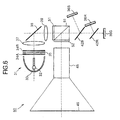
- Figure 8 is a view of the configuration of a fifth embodiment of a projection-type display device according to the present invention.
- a projection-type display device 80 of the fifth embodiment from the projection-type display devices 30, 50, 60, and 70 of the first to fourth embodiments resides in that, in place of the arrangement of the polarization filters or polarization separation elements on the light source side and projection optical system side of the polarization beam splitter, as will be mentioned later, a polarization beam splitter placing predetermined conditions on the structural parameters is constituted, whereby the lowering of the contrast due to the above haze phenomenon is stopped to an extent sufficient for practical use and a high quality image can be displayed.
- a light source 81 is comprised of an xenon lamp 82 arranged in the vicinity of a reflector 83 formed by a substantially parabolic mirror and emits white illumination light from the xenon lamp 82 from an opening of the reflector 83.
- the light source 81 is provided with a pair of fly eye lenses 84A and 84B arranged on the optical path of this illumination light so as to make the distribution of the amount of the illumination light uniform.
- the light source 81 is provided with a plane polarization conversion sheet 85 arranged between these fly eye lenses 84A and 84B.
- the plane polarization conversion sheet 85 is an optical element which mainly selectively transmits the s-polarization component, that is, the polarized light which can be effectively spatially modulated at the reflection-type liquid crystal panels 86A, 86B, and 86C, in this projection-type display device 80 therethrough, and converts p-polarization component orthogonal to this to s-polarization component.
- the light source 81 increases the polarization component effective for the image display in the illumination light emitted with various plane polarizations from the xenon lamp 82, and reduces the polarization component orthogonal to this and emits the resultant illumination light. As a result, the efficiency of utilization of the illumination light is improved and the contrast of the display image is improved.
- the convex lens 87 converges and emits the illumination light on the optical path of the illumination light emitted from the fly eye lens 84B.
- the mirror 88 is struck by the illumination light emitted from this convex lens 87 and reflects and emits this in a 90 degree direction with respect to the path of the incident light.
- a convex lens 89 converges and emits the illumination light reflected at this mirror 88.
- a polarization beam splitter 90 selectively reflects the s-polarization component effective for the image display, and selectively transmits the p-polarization component orthogonal to this therethrough.
- the polarization beam splitter 90 reflects most of the illumination light incident from the convex lens 89 and bends the optical path by 90 degrees, but in contrast selectively transmits the p-polarization component of the optical image of the p-polarization and the s-polarization from the reflection-type liquid crystal panels 86B, 86R, and 86G running in reverse through this optical path.
- the polarization beam splitter 90 having such a function is formed by adhering the inclined facets of rectangular prisms to each other. Dielectric films are laminated on the adhered facets to form detection planes for detecting the incident light.
- each rectangular prism is formed to a length of 50 mm. Due to this, the splitter is formed overall to a cubic shape of a length of 50 mm to a side.
- the polarization beam splitter 90 is configured with the rectangular prisms formed by a glass material having a parameter A indicated by the following equation of a value 3.71 x 10 2 , whereby the birefringence due to the thermal stress is reduced: where,
- the integration range in Equation (1) is a range of the light absorption wavelength band of the glass material (420 nm( ⁇ 1) to 500 nm( ⁇ 2)).
- the dichroic mirror 91B is formed by laminating transparent dielectric films on sheet glass and functions as a wavelength separation mirror which selectively reflects components of predetermined wavelengths in the incident light, and selectively transmits the remaining components therethrough.
- the dichroic mirror 91B selectively reflects the blue band illumination light component in the illumination light emitted from the polarization beam splitter 90, emits this toward the reflection-type liquid crystal panel 86B, and transmits the remaining components therethrough.
- the reflection-type liquid crystal panel 86B is driven by a blue color signal and forms the blue image in the image to be displayed by this projection-type display device 80.
- the reflection-type liquid crystal panel 86B transmits the illumination light incident from the dichroic mirror 91B therethrough, then reflects it at a reflector plate arranged on its back surface, and transmits this therethrough again and emit it and thereby emit the modulated light with a plane polarization rotated according to the blue image.
- the reflection-type liquid crystal panel 86B emits an optical image of the synthesized light of the p-polarized light and the s-polarized light to the dichroic mirror 91B with respect to illumination light emitted by s-polarization.
- the dichroic mirror 91B selectively reflects the modulated light incident from the reflection-type liquid crystal panel 86B in this way and emits this to the polarization beam splitter 90, while transmits the modulated light incident from the further continuing dichroic mirror 91R and emits this to the polarization beam splitter 90.
- the dichroic mirror 91B is arranged inclined by an angle of 45 degrees with respect to the optical axis of the incident light so that the angle ⁇ 1 exhibited by the optical axis of the incident light and the optical axis of the optical image obtained from the reflection-type liquid crystal panel 86B becomes smaller than 90 degrees.
- the dichroic mirror 91B was arranged in this way for the following reason.
- the cutoff wavelength for the selective transmission and reflection is different between the p-polarization component and the s-polarization component which strike at an angle.
- this type of projection-type display device 80 reflects the incident light of the s-polarization component for the reflection-type liquid crystal panel 86B, reflects the optical image of the p-polarization component incident from this reflection-type liquid crystal panel 86B, and emits it to the polarization beam splitter 90. Due to this, when the cutoff wavelength for selective transmission is different between the p-polarization component and the s-polarization component in this way, the efficiency of utilization of the light will be lowered by that amount.
- the projection-type display device 80 is provided with the dichroic mirror 91B arranged inclined at an angle of 45 degrees with respect to the optical axis of the incident light so that the angle ⁇ 1 exhibited by the optical axis of the incident light and the optical axis of the optical image obtained from the reflection-type liquid crystal panel 86B becomes smaller than 90 degrees.
- the reflection-type liquid crystal panel 86B is arranged close to the polarization beam splitter 90 side so that the shape of the entire projection-type display device 80 can be reduced.
- the dichroic mirror 91R functions as a wavelength separation mirror which is formed by laminating transparent dielectric films on sheet glass, selectively reflects the components of predetermined wavelengths in the incident light, and selectively transmits the remaining components therethrough.
- the dichroic mirror 91R selectively reflects the illumination light component of the red band in the illumination light transmitted through the dichroic mirror 91B and emits this toward the reflection-type liquid crystal panel 86R, while transmits the remaining components and emits them toward the reflection-type liquid crystal panel 86G.
- the reflection-type liquid crystal panel 86R is driven by a red color signal and forms the red image in the image to be displayed by this projection-type display device 80.
- the reflection-type liquid crystal panel 86R transmits the illumination light incident from the dichroic mirror 91R therethrough, then reflects it by the reflection plate arranged on its back surface, transmits it again, and emit this and thereby emits modulated light with a plane polarization rotated according to the red image.
- the reflection-type liquid crystal panel 86R emits the optical image of the synthesized light of the p-polarized light and the s-polarized light to the dichroic mirror 91R for the illumination light incident due to the s-polarization.
- the reflection-type liquid crystal panel 86G is driven by a green color signal and forms the green image in the image to be displayed by this projection-type display device 80.
- the reflection-type liquid crystal panel 86G transmits the illumination light incident from the dichroic mirror 91R therethrough, then reflects it by the reflection plate arranged on its back surface, transmits it again, and emits this, thereby to emit modulated light with a plane polarization rotated according to the green image.
- the reflection-type liquid crystal panel 86G emits the optical image of the synthesized light of the p-polarized light and the s-polarized light to the dichroic mirror 91R for the illumination light incident due to the s-polarization.
- the dichroic mirror 91R selectively reflects the modulated light incident from the reflection-type liquid crystal panel 86R in this way and emits this to the dichroic mirror 91B, while transmits the modulated light incident from the reflection-type liquid crystal panel 86G therethrough and emits this to the dichroic mirror 91B.
- the dichroic mirror 91R synthesizing the green and red modulated lights and emitting the result in this way as well, if the wavelength becomes different between the reflection lights of the p-polarization component and the s-polarization component and the incident angle of the incident light becomes small, the difference of cutoff wavelengths becomes smaller by that amount. For this reason, the dichroic mirror 91R is arranged in parallel to the dichroic mirror 91B and arranged inclined at an angle of 45 degrees with respect to the optical axis of the incident light so that the angle ⁇ 2 exhibited by the optical axis of the incident light and the optical axis of the optical image obtained from the reflection-type liquid crystal panel 86R becomes smaller than 90 degrees.
- the reflection-type liquid crystal panel 86R is arranged close to the polarization beam splitter 90 side so that the shape of the projection-type display device 80 can be made smaller as a whole.
- the polarization beam splitter 90 mainly supplies the illumination light due to the s-polarization emitted from the light source 81 to these dichroic mirrors 91B, 91R, etc., and transmits the p-polarization component in the optical image of the synthesized light of the p-polarized light and the s-polarized light generated by the reflection-type liquid crystal panels 86B, 86R, and 86G as a result of this therethrough and emits this toward the screen.
- the projection optical system 92 enlarges and projects the transmitted light of this polarization beam splitter 91 on a screen 93.
- the reflection-type liquid crystal panels 86B, 86R, and 86G are driven by the blue, red, and green color signals and images corresponding to the blue, red, and green color signals are formed on the reflection-type liquid crystal panels 86B, 86R, and 86G.
- the projection-type display device 80 breaks down the illumination light emitted from the light source 81 to wavelengths of blue, red, and green and supplies them to the corresponding reflection-type liquid crystal panels 86B, 86R, and 86G thereby to rotate the plane polarizations of the blue, red, and green illumination lights by images corresponding to the blue, red, and green color signals and generate the optical images, selectively projects the p-polarization components in these optical images by the projection optical system 92 onto the screen 93, and thus projects a colored display image.
- the illumination light emitted from the light source 81 strikes the polarization beam splitter 90 via the mirror 88.
- the s-polarization component to be used for the formation of the optical image is reflected at the reflection-type liquid crystal panels 86B, 86R, and 86G and broken down to the blue, red, and green illumination lights by the continuing dichroic mirrors 91B and 91R.
- the blue, red, and green illumination lights are reflected at the reflection-type liquid crystal panels 86B, 86R, and 86G and blue, red, and green optical images of the synthesized light of the p-polarized light and the s-polarized light are generated.
- optical images strike the polarization beam splitter 90 via the dichroic mirrors 91B and 91R.
- the p-polarization components of the modulated light selectively pass through the polarization beam splitter 90, strike the projection optical system 92, and are projected on the screen 93 by this projection optical system 92.
- the illumination light obliquely strike the dichroic mirrors 91B and 91R by the s-polarization
- the modulated light obliquely strike the dichroic mirrors 91B and 91R as the synthesized light of the p-polarized light and the s-polarized light.
- the dichroic mirrors 91B and 91R have different characteristics of reflection with respect to wavelength between the s-polarized light and the polarized light, so the characteristic of reflection with respect to the wavelength in the illumination light and the characteristic of the reflection in the modulated light become different.
- the dichroic mirrors 91B and 91R are arranged inclined so that the angle exhibited by the optical axis of the illumination light incident on the dichroic mirrors 91B and 91R and the optical axis of the modulated lights incident upon the dichroic mirrors 91B and 91R is made smaller than 90 degrees, therefore the difference of the cutoff wavelength between the reflected light of the s-polarized light and the reflected light of the p-polarized light can be made small.
- the modulated light of the blue, red, and green p-polarization corresponding to the illumination light can be emitted toward the projection optical system 92 with no waste, therefore the efficiency of utilization of the illumination light can be improved by that amount and a bright high quality display image can be formed.
- the illumination light of the s-polarization is spatially modulated at the reflection-type liquid crystal panels 36B, 36R, and 36G and modulated light of the p-polarization and the s-polarization are emitted and strike the polarization beam splitter 90 via the dichroic mirrors 91B and 91R.
- the p-polarization components in the optical images of the p-polarization and the s-polarization are transmitted and emitted toward the screen.
- the s-polarization components of the optical images are separated from the optical images by the p-polarization at the polarization beam splitter 90 and must not to be projected on the screen 93.
- the p-polarization component is emitted toward the reflection-type liquid crystal panels 86B, 86R, and 86G by the detection at the detection facet of the polarization beam splitter 90, but at this time, due to the birefringence of the rectangular prisms constituting the polarization beam splitter 90, the s-polarization component is mixed into the p-polarization component and emitted. This s-polarization component will be reflected at the reflection-type liquid crystal panels 86B, 86R, and 86G and then pass through the polarization beam splitter 90 and be projected on the screen 93. Thus the contrast of the display image will be lowered by that amount.
- the rectangular prisms are formed by a glass material having the parameter A indicated by Equation (1) with the value 3.71 x 10 2 , the p-polarization component and the s-polarization component increasing due to the birefringence can be stopped in a range enough for practical use, and the lowering of the contrast due to the above haze phenomenon is prevented by that amount.
- the degree of the birefringence can be reduced in the rectangular prisms constituting the polarization beam splitter 90 from causes of the above haze phenomenon, the phenomenon can be reduced by that amount.
- This birefringence occurs due to the stress inside the glass material and can be determined by the value of the optical path length x optical elastic constant x stress indicating the amount of strain of the glass material as a yardstick.
- the optical elastic constant has a constant value dependent upon the glass material, therefore it has been considered that this type of haze phenomenon can be reduced by managing this optical elastic constant.
- the optical elastic constant is greatly reduced, if it is a glass material having a large stress, it becomes difficult to reduce the birefringence by that amount.
- the stress is represented by thermal stress + initial stress + attachment stress.
- the thermal stress is the stress of displacement according to the temperature rise of the glass material. In the projection-type display device 80, it occurs due to a temperature rise due to thermal convection inside the set, heat conductivity, loss of illumination light, or the like.
- the initial stress is a residual stress from the time of fabrication of the polarization beam splitter 90 and is generated due to the residual stress when the glass material becomes hard, the residual stress at the cutting and polishing of the glass material, the residual stress due to the heat when forming the detection facet, the shrinkage of the bonding material at adhesion, and so on.
- the attachment stress is a stress that is added to the polarization beam splitter 90 when the polarization beam splitter 90 is arranged.
- the thermal stress when further considering this thermal stress, it is possible to represent the thermal stress by physical constants defining the characteristics of this type of glass material and to thereby represent it by the temperature difference x linear expansion coefficient x Young's modules. Further, the temperature difference can be represented by the specific heat, specific gravity, and transmittance.
- the illumination light can be supplied in an uniform amount by the fly eye lenses 84A and 84B arranged in the light source 81, and the unevenness of luminance of the display image can be prevented by that amount. Due to this, it becomes possible to display a high quality display image due to this as well.
- the plane polarization conversion sheet 85 arranged between these fly eye lenses 84A and 84B, the p-polarization component which passes through the polarization beam splitter 90 and is never used for the display of the image is partially converted to a s-polarization component and emitted, whereby the efficiency of utilization of the illumination light is increased by that amount, and the luminance level of the display image is improved. Due to this as well, it becomes possible to display a high quality display image.
- the polarization beam splitter is prepared by using a glass material having a parameter A indicating the degree of the birefringence due to the thermal stress shown by Equation (1) with a value of 3.71 x 10 2 , which is a value lower than 5.00 x 10 2 , the reduction of the contrast due to the above haze phenomenon can be stopped to an extent enough for practical use. Due to this, a high quality display image can be displayed.
- the change of the contrast due to heat is small, even if it is turned on for a long time, it becomes possible to obtain a stable contrast and uniformity. Further, the thermal stress characteristic of the material with respect to an increase of the amount of light accompanying an increase of the luminance of the display image is improved, whereby it becomes easy to increase the luminance.
- the dichroic mirror since the dichroic mirror was arranged inclined so that the angle exhibited by the optical axis of the illumination light incident on the dichroic mirror serving as the wavelength separation mirror and the optical axis of the modulated light becomes an angle smaller than 90 degrees, it becomes possible to reduce the difference of the wavelength in the p-polarization component and the s-polarization component of the reflected light in a configuration for generating modulated light of p-polarization and s-polarization from illumination light of s-polarization and projecting the same on a screen, the efficiency of utilization of the illumination light can be improved by that amount, and, as a result, a high quality image can be displayed.
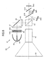
- Figure 10 is a view of the configuration of a sixth embodiment of a projection-type display device according to the present invention.
- the illumination light is broken down into blue, red, and green illumination light by the dichroic prism 101 and blue, red, and green optical images are synthesized.
- this dichroic prism 10 is prepared by using a glass material having a parameter A indicated by Equation (1) with a value of 3.71 x 10 2 .
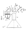
- Figure 11 is a view of the configuration of a seventh embodiment of a projection-type display device according to the present invention.
- a polarization beam splitter 111 having different transmitting and reflecting plane polarizations from those of the polarization beam splitter 90 of the projection-type display device 80 of the fifth embodiment is arranged and the arrangement of the optical system is changed corresponding to this.
- this projection-type display device 110 the same configurations as those of the projection-type display device 80 are indicated by corresponding references and overlapping explanations will be omitted.
- the polarization beam splitter 111 is prepared by using a glass material having a parameter A indicating the degree of the birefringence due to the thermal stress with a value of 3.71 x 10 2 , transmits the s-polarized beam therethrough, and reflects the p-polarized light.
- the dichroic mirror 91B etc. are arranged on the optical path of the illumination light passing through the polarization beam splitter 111.
- polarization separation elements 112 and 113 are arranged on the light source side and the projection optical system side of the polarization beam splitter 111.
- the polarization separation elements 112 and 113 are formed by laminating films of predetermined thicknesses having optical anisotropy and selectively transmit the incident light of predetermined plane polarizations shown in Fig. 12 therethrough, while selectively reflect incident light having plane polarizations orthogonal to this.
- the polarization separation element 112 is arranged between the convex lens 89 and the polarization beam splitter 111, selectively transmits the s-polarization component in the illumination light incident from the light source 81 therethrough, while selectively reflects the p-polarization component.
- the polarization separation element 113 is arranged between the projection optical system 92 and the polarization beam splitter 111, selectively transmits the p-polarization component in the incident light from the polarization beam splitter 111 therethrough, while selectively reflects the s-polarization component.
- the polarization separation elements 112 and 113 reflect the components of the plane polarization which become the cause of the above haze phenomenon to the light source side and can utilize them again and improve the contrast of the display image and, at the same time, efficiently utilize the illumination light and improve the luminance level of the display image.
- the polarization separation elements 112 and 113 are held adhered to the incident facet and the emission facet of the polarization beam splitter 111.
- the projection-type display device 110 eliminates the air layer between the polarization separation element 112 and the polarization beam splitter 111 and the air layer between the polarization separation element 113 and the polarization beam splitter 111 and prevents the loss of the light due to these air layers.
- the projection-type display device 110 efficiently radiates the heat generated at the polarization separation elements 112 and 113 and reduces the temperature rise.
- the polarization separation elements 112 and 113 are arranged between the light source 81 and the polarization beam splitter 111 and between the projection optical system 92 and the polarization beam splitter 111, the above haze phenomenon can be further prevented. Due to this, the contrast is improved and a high quality display image can be formed.
Landscapes
- Physics & Mathematics (AREA)
- General Physics & Mathematics (AREA)
- Optics & Photonics (AREA)
- Engineering & Computer Science (AREA)
- Multimedia (AREA)
- Signal Processing (AREA)
- Projection Apparatus (AREA)
- Liquid Crystal (AREA)
Applications Claiming Priority (7)
| Application Number | Priority Date | Filing Date | Title |
|---|---|---|---|
| JP10275370A JP2000105360A (ja) | 1998-09-29 | 1998-09-29 | 投射型表示装置 |
| JP27537098 | 1998-09-29 | ||
| JP27697498 | 1998-09-30 | ||
| JP27697498 | 1998-09-30 | ||
| JP10301953A JP2000171770A (ja) | 1998-09-30 | 1998-10-23 | 投射型表示装置 |
| JP30195398 | 1998-10-23 | ||
| EP99119244A EP0991281A3 (fr) | 1998-09-29 | 1999-09-28 | Dispositif de projection d'images |
Related Parent Applications (2)
| Application Number | Title | Priority Date | Filing Date |
|---|---|---|---|
| EP99119244.4 Division | 1999-09-28 | ||
| EP99119244A Division EP0991281A3 (fr) | 1998-09-29 | 1999-09-28 | Dispositif de projection d'images |
Publications (3)
| Publication Number | Publication Date |
|---|---|
| EP1585344A2 true EP1585344A2 (fr) | 2005-10-12 |
| EP1585344A3 EP1585344A3 (fr) | 2008-01-02 |
| EP1585344B1 EP1585344B1 (fr) | 2013-05-22 |
Family
ID=27336255
Family Applications (2)
| Application Number | Title | Priority Date | Filing Date |
|---|---|---|---|
| EP05014061.5A Expired - Lifetime EP1585344B1 (fr) | 1998-09-29 | 1999-09-28 | Dispositif d'affichage de type projecteur |
| EP99119244A Ceased EP0991281A3 (fr) | 1998-09-29 | 1999-09-28 | Dispositif de projection d'images |
Family Applications After (1)
| Application Number | Title | Priority Date | Filing Date |
|---|---|---|---|
| EP99119244A Ceased EP0991281A3 (fr) | 1998-09-29 | 1999-09-28 | Dispositif de projection d'images |
Country Status (3)
| Country | Link |
|---|---|
| US (2) | US6394606B1 (fr) |
| EP (2) | EP1585344B1 (fr) |
| CN (1) | CN1236625C (fr) |
Families Citing this family (30)
| Publication number | Priority date | Publication date | Assignee | Title |
|---|---|---|---|---|
| IL132928A0 (en) * | 1999-11-14 | 2001-03-19 | Unic View Ltd | Thermally stable birefringent prism assembly |
| JP2002090696A (ja) | 2000-09-20 | 2002-03-27 | Sony Corp | 光学装置及び投射型表示装置 |
| JP3766586B2 (ja) * | 2000-10-02 | 2006-04-12 | 株式会社日立製作所 | 光学エンジン、映像表示装置及び色切替方法 |
| US6469834B1 (en) | 2000-11-16 | 2002-10-22 | Koninklijke Philips Electronics N.V. | System and method for elimination of scattered side lobes created by integrator lenslet arrays |
| JP3838028B2 (ja) | 2000-12-18 | 2006-10-25 | セイコーエプソン株式会社 | 投射型表示装置 |
| KR100451733B1 (ko) | 2000-12-28 | 2004-10-08 | 엘지전자 주식회사 | 화상 투사 장치 |
| US6669343B2 (en) * | 2001-05-31 | 2003-12-30 | Koninklijke Philips Electronics N.V. | Image display system |
| JP4834934B2 (ja) * | 2001-07-25 | 2011-12-14 | 株式会社ニコン | 色合成光学装置及び投射型表示装置 |
| CN1249485C (zh) * | 2001-09-04 | 2006-04-05 | 佳能株式会社 | 色分解光学系统、图象显示光学系统和投影式图象显示装置 |
| CN1227555C (zh) * | 2001-11-27 | 2005-11-16 | 佳能株式会社 | 投影型图像显示装置与图像显示系统 |
| JP3730582B2 (ja) * | 2002-03-04 | 2006-01-05 | 株式会社日立製作所 | 色分離合成光学系及びそれを用いた投写型液晶表示装置 |
| JP3909595B2 (ja) * | 2003-04-23 | 2007-04-25 | セイコーエプソン株式会社 | 表示装置、及びその調光方法 |
| US7281807B2 (en) * | 2003-07-16 | 2007-10-16 | Honeywood Technologies, Llc | Positionable projection display devices |
| US7156522B2 (en) * | 2003-07-16 | 2007-01-02 | Plut William J | Projection-type display devices with reduced weight and size |
| JP4422986B2 (ja) * | 2003-08-22 | 2010-03-03 | キヤノン株式会社 | 画像表示装置 |
| US8238019B2 (en) * | 2003-11-01 | 2012-08-07 | Silicon Quest Kabushiki-Kaisha | Projection apparatus with coherent light source |
| US7023619B2 (en) * | 2004-06-17 | 2006-04-04 | Hewlett-Packard Development Company, L.P. | Digital projection system optical reflector having facets |
| JP4444745B2 (ja) * | 2004-07-08 | 2010-03-31 | キヤノン株式会社 | 偏光分離素子および画像投射装置 |
| JP4059233B2 (ja) * | 2004-07-23 | 2008-03-12 | セイコーエプソン株式会社 | 画像表示装置およびプロジェクタ |
| JP4432933B2 (ja) * | 2005-07-08 | 2010-03-17 | セイコーエプソン株式会社 | 画像表示装置および画像表示方法 |
| US20070279595A1 (en) * | 2006-06-02 | 2007-12-06 | 3M Innovative Properties Company | Illumination system and projection system using same |
| US20080158669A1 (en) * | 2006-12-29 | 2008-07-03 | 3M Innovative Properties Company | Projection screen apparatus for use with portable digital projectors |
| JP5333215B2 (ja) * | 2007-05-31 | 2013-11-06 | 株式会社ニコン | チューナブルフィルタ、光源装置およびスペクトル分布測定装置 |
| US8003556B2 (en) * | 2007-09-28 | 2011-08-23 | Ohara Inc. | Optical glass |
| CN101397187B (zh) * | 2007-09-29 | 2012-11-28 | 株式会社小原 | 光学玻璃 |
| CN102320739B (zh) * | 2007-09-29 | 2015-04-01 | 株式会社小原 | 光学玻璃 |
| GB201108000D0 (en) * | 2011-05-13 | 2011-06-29 | Barco Nv | Polarization preserving dlp optical architecture |
| JP6019891B2 (ja) * | 2012-07-30 | 2016-11-02 | セイコーエプソン株式会社 | 光源装置及びプロジェクター |
| CN110099818A (zh) * | 2016-12-21 | 2019-08-06 | 富士胶片株式会社 | 投影型显示装置、投影型显示装置的控制方法、投影型显示装置的控制程序 |
| CN111881719B (zh) * | 2020-06-09 | 2024-04-16 | 青岛奥美克生物信息科技有限公司 | 非接触式生物识别引导装置、方法以及生物特征识别系统 |
Citations (8)
| Publication number | Priority date | Publication date | Assignee | Title |
|---|---|---|---|---|
| JPH02211418A (ja) * | 1989-02-13 | 1990-08-22 | Seiko Epson Corp | 光学装置 |
| US5327270A (en) * | 1989-03-23 | 1994-07-05 | Matsushita Electric Industrial Co., Ltd. | Polarizing beam splitter apparatus and light valve image projection system |
| WO1995017303A1 (fr) * | 1993-12-21 | 1995-06-29 | Minnesota Mining And Manufacturing Company | Film optique multicouche |
| WO1998007279A1 (fr) * | 1996-08-12 | 1998-02-19 | National Research Council Of Canada | Dispositif d'affichage de projection extremement efficace possedant des diviseurs de faisceau de polarisation a couche mince |
| EP0827006A2 (fr) * | 1996-09-02 | 1998-03-04 | Sony Corporation | Dispositif de projection avec des moyens de séparation/synthèse des couleurs |
| WO1998023993A1 (fr) * | 1996-11-28 | 1998-06-04 | Sony Corporation | Bloc optique et unite d'affichage |
| US5786873A (en) * | 1995-03-23 | 1998-07-28 | International Business Machines Corporation | Efficient optical system for a high resolution projection display employing reflection light valves |
| US5808795A (en) * | 1995-03-06 | 1998-09-15 | Nikon Corporation | Projection type display apparatus |
Family Cites Families (12)
| Publication number | Priority date | Publication date | Assignee | Title |
|---|---|---|---|---|
| US5648860A (en) * | 1992-10-09 | 1997-07-15 | Ag Technology Co., Ltd. | Projection type color liquid crystal optical apparatus |
| JPH07218723A (ja) * | 1994-02-07 | 1995-08-18 | Nikon Corp | 偏光子 |
| EP0671854B1 (fr) * | 1994-03-09 | 2000-05-31 | Daewoo Electronics Co., Ltd | Système optique de projection |
| EP0734182B1 (fr) * | 1995-03-23 | 2001-01-17 | International Business Machines Corporation | Système optique efficace pour un écran de projection haute résolution employant des valves de lumière à réflexion |
| US5621486A (en) * | 1995-06-22 | 1997-04-15 | International Business Machines Corporation | Efficient optical system for a high resolution projection display employing reflection light valves |
| JPH09113863A (ja) * | 1995-10-20 | 1997-05-02 | Nikon Corp | 投射型表示装置 |
| JP3738505B2 (ja) * | 1996-05-10 | 2006-01-25 | 株式会社ニコン | 投射型表示装置 |
| US6111700A (en) * | 1996-09-05 | 2000-08-29 | Fujitsu Limited | Optical display device having a reflection-type polarizer |
| JP3501963B2 (ja) * | 1997-12-22 | 2004-03-02 | シャープ株式会社 | 投影型画像表示装置 |
| US5986815A (en) * | 1998-05-15 | 1999-11-16 | Optical Coating Laboratory, Inc. | Systems, methods and apparatus for improving the contrast ratio in reflective imaging systems utilizing color splitters |
| JP2000010050A (ja) * | 1998-06-23 | 2000-01-14 | Minolta Co Ltd | プロジェクター光学系 |
| US6082861A (en) * | 1998-09-16 | 2000-07-04 | International Business Machines Corporation | Optical system and method for high contrast projection display |
-
1999
- 1999-09-23 US US09/404,020 patent/US6394606B1/en not_active Expired - Lifetime
- 1999-09-28 EP EP05014061.5A patent/EP1585344B1/fr not_active Expired - Lifetime
- 1999-09-28 EP EP99119244A patent/EP0991281A3/fr not_active Ceased
- 1999-09-29 CN CNB991224736A patent/CN1236625C/zh not_active Expired - Fee Related
-
2001
- 2001-10-22 US US10/039,329 patent/US6783241B2/en not_active Expired - Fee Related
Patent Citations (9)
| Publication number | Priority date | Publication date | Assignee | Title |
|---|---|---|---|---|
| JPH02211418A (ja) * | 1989-02-13 | 1990-08-22 | Seiko Epson Corp | 光学装置 |
| US5327270A (en) * | 1989-03-23 | 1994-07-05 | Matsushita Electric Industrial Co., Ltd. | Polarizing beam splitter apparatus and light valve image projection system |
| WO1995017303A1 (fr) * | 1993-12-21 | 1995-06-29 | Minnesota Mining And Manufacturing Company | Film optique multicouche |
| US5808795A (en) * | 1995-03-06 | 1998-09-15 | Nikon Corporation | Projection type display apparatus |
| US5786873A (en) * | 1995-03-23 | 1998-07-28 | International Business Machines Corporation | Efficient optical system for a high resolution projection display employing reflection light valves |
| WO1998007279A1 (fr) * | 1996-08-12 | 1998-02-19 | National Research Council Of Canada | Dispositif d'affichage de projection extremement efficace possedant des diviseurs de faisceau de polarisation a couche mince |
| EP0827006A2 (fr) * | 1996-09-02 | 1998-03-04 | Sony Corporation | Dispositif de projection avec des moyens de séparation/synthèse des couleurs |
| WO1998023993A1 (fr) * | 1996-11-28 | 1998-06-04 | Sony Corporation | Bloc optique et unite d'affichage |
| US6144492A (en) * | 1996-11-28 | 2000-11-07 | Sony Corporation | Optical block and display unit |
Non-Patent Citations (1)
| Title |
|---|
| DOANY F E ET AL: "PROJECTION DISPLAY THROUGHPUT: EFFICIENCY OF OPTICAL TRANSMISSION AND LIGHT-SOURCE COLLECTION", IBM JOURNAL OF RESEARCH AND DEVELOPMENT, INTERNATIONAL BUSINESS MACHINES CORPORATION, NEW YORK, NY, US, vol. 42, no. 3/04, 1 July 1998 (1998-07-01), pages 387-399, XP000955102, ISSN: 0018-8646 * |
Also Published As
| Publication number | Publication date |
|---|---|
| US6394606B1 (en) | 2002-05-28 |
| CN1253456A (zh) | 2000-05-17 |
| EP1585344A3 (fr) | 2008-01-02 |
| US6783241B2 (en) | 2004-08-31 |
| CN1236625C (zh) | 2006-01-11 |
| EP0991281A2 (fr) | 2000-04-05 |
| US20020122157A1 (en) | 2002-09-05 |
| EP0991281A3 (fr) | 2004-04-14 |
| EP1585344B1 (fr) | 2013-05-22 |
Similar Documents
| Publication | Publication Date | Title |
|---|---|---|
| EP1585344B1 (fr) | Dispositif d'affichage de type projecteur | |
| US6331060B1 (en) | Projection-type display device and method of adjustment thereof | |
| US6992822B2 (en) | Projection display system using a diffuse reflecting polarizer | |
| JP3444521B2 (ja) | 投影型画像表示装置 | |
| US9341883B2 (en) | Display module and light guide device | |
| US20080094576A1 (en) | Projection system incorporating color correcting element | |
| US6811261B2 (en) | Projection display apparatus | |
| US7258445B2 (en) | Polarization splitter, optical unit and image projector | |
| US6132047A (en) | Polarized light illumination device and projector | |
| JP2000356770A (ja) | 液晶プロジェクタ | |
| JP2000171770A (ja) | 投射型表示装置 | |
| JP2009103863A (ja) | 位相差板及びプロジェクタ | |
| KR20030090021A (ko) | 반사형 평판 편광판을 이용한 프로젝션 시스템 | |
| US6612702B1 (en) | Projection display device | |
| EP1130450A1 (fr) | Illuminateur a lumiere polarisee et affichage de projection | |
| JP3659637B2 (ja) | 投影型画像表示装置 | |
| JP2003337375A (ja) | プロジェクタ | |
| JP3797100B2 (ja) | プロジェクタ | |
| JP2009128568A (ja) | 偏光変換素子及びプロジェクタ | |
| WO2021015101A1 (fr) | Dispositif d'affichage | |
| KR100359728B1 (ko) | 액정 프로젝터의 광학 장치 | |
| JP2000105360A (ja) | 投射型表示装置 | |
| JP3641558B2 (ja) | クロスダイクロイックミラーおよびこれを用いた画像投影装置 | |
| JPH1184368A (ja) | 液晶プロジェクター | |
| JP2006338030A (ja) | 光学装置及び光学装置を備える表示装置 |
Legal Events
| Date | Code | Title | Description |
|---|---|---|---|
| PUAI | Public reference made under article 153(3) epc to a published international application that has entered the european phase |
Free format text: ORIGINAL CODE: 0009012 |
|
| 17P | Request for examination filed |
Effective date: 20050629 |
|
| AC | Divisional application: reference to earlier application |
Ref document number: 0991281 Country of ref document: EP Kind code of ref document: P |
|
| AK | Designated contracting states |
Kind code of ref document: A2 Designated state(s): DE FR GB |
|
| PUAL | Search report despatched |
Free format text: ORIGINAL CODE: 0009013 |
|
| AK | Designated contracting states |
Kind code of ref document: A3 Designated state(s): DE FR GB |
|
| AKX | Designation fees paid |
Designated state(s): DE FR GB |
|
| 17Q | First examination report despatched |
Effective date: 20081030 |
|
| GRAP | Despatch of communication of intention to grant a patent |
Free format text: ORIGINAL CODE: EPIDOSNIGR1 |
|
| GRAS | Grant fee paid |
Free format text: ORIGINAL CODE: EPIDOSNIGR3 |
|
| GRAA | (expected) grant |
Free format text: ORIGINAL CODE: 0009210 |
|
| AC | Divisional application: reference to earlier application |
Ref document number: 0991281 Country of ref document: EP Kind code of ref document: P |
|
| AK | Designated contracting states |
Kind code of ref document: B1 Designated state(s): DE FR GB |
|
| REG | Reference to a national code |
Ref country code: GB Ref legal event code: FG4D |
|
| REG | Reference to a national code |
Ref country code: DE Ref legal event code: R096 Ref document number: 69944758 Country of ref document: DE Effective date: 20130711 |
|
| PLBE | No opposition filed within time limit |
Free format text: ORIGINAL CODE: 0009261 |
|
| STAA | Information on the status of an ep patent application or granted ep patent |
Free format text: STATUS: NO OPPOSITION FILED WITHIN TIME LIMIT |
|
| 26N | No opposition filed |
Effective date: 20140225 |
|
| REG | Reference to a national code |
Ref country code: DE Ref legal event code: R097 Ref document number: 69944758 Country of ref document: DE Effective date: 20140225 |
|
| PGFP | Annual fee paid to national office [announced via postgrant information from national office to epo] |
Ref country code: DE Payment date: 20140922 Year of fee payment: 16 |
|
| PGFP | Annual fee paid to national office [announced via postgrant information from national office to epo] |
Ref country code: FR Payment date: 20140919 Year of fee payment: 16 Ref country code: GB Payment date: 20140919 Year of fee payment: 16 |
|
| REG | Reference to a national code |
Ref country code: DE Ref legal event code: R119 Ref document number: 69944758 Country of ref document: DE |
|
| GBPC | Gb: european patent ceased through non-payment of renewal fee |
Effective date: 20150928 |
|
| REG | Reference to a national code |
Ref country code: FR Ref legal event code: ST Effective date: 20160531 |
|
| PG25 | Lapsed in a contracting state [announced via postgrant information from national office to epo] |
Ref country code: DE Free format text: LAPSE BECAUSE OF NON-PAYMENT OF DUE FEES Effective date: 20160401 Ref country code: GB Free format text: LAPSE BECAUSE OF NON-PAYMENT OF DUE FEES Effective date: 20150928 |
|
| PG25 | Lapsed in a contracting state [announced via postgrant information from national office to epo] |
Ref country code: FR Free format text: LAPSE BECAUSE OF NON-PAYMENT OF DUE FEES Effective date: 20150930 |