EP1585201B1 - Connecteur - Google Patents
Connecteur Download PDFInfo
- Publication number
- EP1585201B1 EP1585201B1 EP05012056A EP05012056A EP1585201B1 EP 1585201 B1 EP1585201 B1 EP 1585201B1 EP 05012056 A EP05012056 A EP 05012056A EP 05012056 A EP05012056 A EP 05012056A EP 1585201 B1 EP1585201 B1 EP 1585201B1
- Authority
- EP
- European Patent Office
- Prior art keywords
- plug connector
- screen
- connector
- securing
- complementary
- Prior art date
- Legal status (The legal status is an assumption and is not a legal conclusion. Google has not performed a legal analysis and makes no representation as to the accuracy of the status listed.)
- Expired - Lifetime
Links
- 230000000295 complement effect Effects 0.000 claims abstract description 64
- 230000000903 blocking effect Effects 0.000 claims description 2
- 238000012216 screening Methods 0.000 abstract 2
- 238000003780 insertion Methods 0.000 description 51
- 230000037431 insertion Effects 0.000 description 51
- 230000013011 mating Effects 0.000 description 28
- 238000004519 manufacturing process Methods 0.000 description 9
- 238000005452 bending Methods 0.000 description 7
- 238000002347 injection Methods 0.000 description 7
- 239000007924 injection Substances 0.000 description 7
- 210000002105 tongue Anatomy 0.000 description 7
- 239000004020 conductor Substances 0.000 description 6
- 239000000758 substrate Substances 0.000 description 6
- 239000002184 metal Substances 0.000 description 5
- 238000007373 indentation Methods 0.000 description 3
- 230000035939 shock Effects 0.000 description 3
- 230000005540 biological transmission Effects 0.000 description 2
- 238000010276 construction Methods 0.000 description 2
- 230000003993 interaction Effects 0.000 description 2
- 238000005304 joining Methods 0.000 description 2
- 230000008878 coupling Effects 0.000 description 1
- 238000010168 coupling process Methods 0.000 description 1
- 238000005859 coupling reaction Methods 0.000 description 1
- 238000002788 crimping Methods 0.000 description 1
- 238000013461 design Methods 0.000 description 1
- 238000011161 development Methods 0.000 description 1
- 230000018109 developmental process Effects 0.000 description 1
- 238000006073 displacement reaction Methods 0.000 description 1
- 230000000694 effects Effects 0.000 description 1
- 230000005684 electric field Effects 0.000 description 1
- 230000005672 electromagnetic field Effects 0.000 description 1
- 230000005670 electromagnetic radiation Effects 0.000 description 1
- 238000001746 injection moulding Methods 0.000 description 1
- 238000000034 method Methods 0.000 description 1
- 238000004080 punching Methods 0.000 description 1
- 238000012549 training Methods 0.000 description 1
Images


Classifications
-
- H—ELECTRICITY
- H01—ELECTRIC ELEMENTS
- H01R—ELECTRICALLY-CONDUCTIVE CONNECTIONS; STRUCTURAL ASSOCIATIONS OF A PLURALITY OF MUTUALLY-INSULATED ELECTRICAL CONNECTING ELEMENTS; COUPLING DEVICES; CURRENT COLLECTORS
- H01R13/00—Details of coupling devices of the kinds covered by groups H01R12/70 or H01R24/00 - H01R33/00
- H01R13/648—Protective earth or shield arrangements on coupling devices, e.g. anti-static shielding
-
- H—ELECTRICITY
- H01—ELECTRIC ELEMENTS
- H01R—ELECTRICALLY-CONDUCTIVE CONNECTIONS; STRUCTURAL ASSOCIATIONS OF A PLURALITY OF MUTUALLY-INSULATED ELECTRICAL CONNECTING ELEMENTS; COUPLING DEVICES; CURRENT COLLECTORS
- H01R12/00—Structural associations of a plurality of mutually-insulated electrical connecting elements, specially adapted for printed circuits, e.g. printed circuit boards [PCB], flat or ribbon cables, or like generally planar structures, e.g. terminal strips, terminal blocks; Coupling devices specially adapted for printed circuits, flat or ribbon cables, or like generally planar structures; Terminals specially adapted for contact with, or insertion into, printed circuits, flat or ribbon cables, or like generally planar structures
- H01R12/70—Coupling devices
- H01R12/71—Coupling devices for rigid printing circuits or like structures
- H01R12/72—Coupling devices for rigid printing circuits or like structures coupling with the edge of the rigid printed circuits or like structures
- H01R12/722—Coupling devices for rigid printing circuits or like structures coupling with the edge of the rigid printed circuits or like structures coupling devices mounted on the edge of the printed circuits
- H01R12/724—Coupling devices for rigid printing circuits or like structures coupling with the edge of the rigid printed circuits or like structures coupling devices mounted on the edge of the printed circuits containing contact members forming a right angle
-
- H—ELECTRICITY
- H01—ELECTRIC ELEMENTS
- H01R—ELECTRICALLY-CONDUCTIVE CONNECTIONS; STRUCTURAL ASSOCIATIONS OF A PLURALITY OF MUTUALLY-INSULATED ELECTRICAL CONNECTING ELEMENTS; COUPLING DEVICES; CURRENT COLLECTORS
- H01R13/00—Details of coupling devices of the kinds covered by groups H01R12/70 or H01R24/00 - H01R33/00
- H01R13/648—Protective earth or shield arrangements on coupling devices, e.g. anti-static shielding
- H01R13/658—High frequency shielding arrangements, e.g. against EMI [Electro-Magnetic Interference] or EMP [Electro-Magnetic Pulse]
-
- H—ELECTRICITY
- H01—ELECTRIC ELEMENTS
- H01R—ELECTRICALLY-CONDUCTIVE CONNECTIONS; STRUCTURAL ASSOCIATIONS OF A PLURALITY OF MUTUALLY-INSULATED ELECTRICAL CONNECTING ELEMENTS; COUPLING DEVICES; CURRENT COLLECTORS
- H01R12/00—Structural associations of a plurality of mutually-insulated electrical connecting elements, specially adapted for printed circuits, e.g. printed circuit boards [PCB], flat or ribbon cables, or like generally planar structures, e.g. terminal strips, terminal blocks; Coupling devices specially adapted for printed circuits, flat or ribbon cables, or like generally planar structures; Terminals specially adapted for contact with, or insertion into, printed circuits, flat or ribbon cables, or like generally planar structures
- H01R12/70—Coupling devices
- H01R12/7005—Guiding, mounting, polarizing or locking means; Extractors
-
- H—ELECTRICITY
- H01—ELECTRIC ELEMENTS
- H01R—ELECTRICALLY-CONDUCTIVE CONNECTIONS; STRUCTURAL ASSOCIATIONS OF A PLURALITY OF MUTUALLY-INSULATED ELECTRICAL CONNECTING ELEMENTS; COUPLING DEVICES; CURRENT COLLECTORS
- H01R13/00—Details of coupling devices of the kinds covered by groups H01R12/70 or H01R24/00 - H01R33/00
- H01R13/46—Bases; Cases
- H01R13/516—Means for holding or embracing insulating body, e.g. casing, hoods
-
- H—ELECTRICITY
- H01—ELECTRIC ELEMENTS
- H01R—ELECTRICALLY-CONDUCTIVE CONNECTIONS; STRUCTURAL ASSOCIATIONS OF A PLURALITY OF MUTUALLY-INSULATED ELECTRICAL CONNECTING ELEMENTS; COUPLING DEVICES; CURRENT COLLECTORS
- H01R2201/00—Connectors or connections adapted for particular applications
- H01R2201/26—Connectors or connections adapted for particular applications for vehicles
Definitions
- a connector with a contact element receptacle for receiving a contact element, a contact element receiving the partially surrounding shield and a contact element receiving and the shield partially receiving housing is known from US-A-4,900,262.
- a connector having the features of the preamble of claim 1 is known from EP-A-0 562 311.
- the connector according to the invention for mating with a complementary connector in a plugging direction in particular for use in a motor vehicle, has a contact element receptacle for receiving a contact element, preferably at least two contact elements, a contact element receiving at least partially surrounding shield and a contact element receiving and the shield at least partially receiving housing on.
- the contact element receptacle for receiving at least two, more preferably more than two contact elements is formed.
- Such a connector is then particularly suitable for connecting lines of a bus system in a motor vehicle, which often have multiple wires.
- any contact elements such as pins, tongues or blades or contact sockets, can be used.
- the contact elements can be connected to conductors, which in the context of the invention not only wires of cables are understood, but also tracks on circuit boards.
- the shield made of an electrically conductive material, preferably a metal, serves to shield contact elements in the contact element receptacle against electric and electromagnetic fields.
- it can have a contacting device to which a conductor with a reference potential, for example ground, can be connected.
- the shield preferably receives the contact element receptacle.
- the shields of the connector and the complementary connector may be suitably designed so that upon mating of the connector, an electrical contact between the shields is made.
- the contact element receptacle and the at least partially surrounding shield are at least partially surrounded by the housing, which protects it against external influences and in particular can also be designed for mechanical connection to a complementary plug connector or its housing.
- the housing of the connector and / or the complementary connector may have guides, by means of which the plug-in connector when mating or are feasible in one another.
- the shield has at least one securing element, preferably a snap or latching element, on the mating of the connector with a corresponding complementary connector relative to a complementary securing element of the complementary connector, preferably a complementary snap or locking element, in a securing position relative to the complementary Fuse element is movable and by means of which in the backup position by interaction with the complementary securing element, a relative movement of the connector from the mated position is limited out.
- the complementary connector may be formed in particular as a suitably designed connector with a corresponding complementary fuse element.
- Another object of the invention is a connector system with a first connector according to the invention and a mating with the first connector, complementary to this second connector.
- the complementary second connector can for this purpose in particular in a trained accordingly Contact element receiving arranged, corresponding to the contact elements of the first connector complementary second contact elements and a housing which allows mating with the housing of the first connector having.
- the connector system according to the invention allows a simple connection of a shielded cable with another, in particular also shielded, line or a circuit carrier, wherein the contacting region is at least partially shielded and thus low-interference.
- the housing may in principle be of any desired construction, however, an embodiment is preferred in which the housing is composed of at least two housing parts, in particular put together and / or pushed.
- The, preferably designed as a plastic injection molded parts, housing parts may have fastening elements by which they are optionally connected to each other movable.
- the connector is then easily assembled by joining the contact element receptacle, the shield and the housing. In particular, a sprinkling of the housing can be avoided to a line, if this can be enclosed by mating the housing parts.
- the housing parts can preferably have corresponding indentations in edge areas, which form an opening for receiving the line only after joining the housing parts.
- the indentations may preferably comprise portions of a sleeve, which after assembly of the housing surrounds a conduit.
- the line can then be installed in the assembly of the housing parts in the housing. This may be particularly advantageous when the contact elements are to be connected to the line prior to assembly of the connector to allow easy handling during assembly. The production of such a connector as well as its connection to a line is then particularly cost.
- the housing is formed in one piece, and comprises a sleeve-shaped portion into which the shield is inserted with the contact element receptacle.
- the shield with the contact element receiving is inserted by a relative movement between the housing and the shield with the contact element receiving in the sleeve-shaped portion, so that the housing can be pushed over the shield.
- Such a housing is particularly simple and stable. Furthermore, it is easy to produce by plastic injection molding.
- the housing then has a flap for at least partially closing an opening, through which the shield with the contact element receptacle can be inserted into the housing. If appropriate, the flap can have an indentation in an edge region through which a conduit can be guided.
- the shield is formed from one or more stamped and bent parts.
- the shield is so very simple and can be produced fully or over a large area.
- the shielding as completely as possible, in particular substantially up to the end faces of the contact element receptacle, the contact element receptacle, at or in which parts of contact elements are arranged, the same encloses. In essence, this means in particular that small production-related gaps or holes can occur at seams or corners, but preferably not in areas.
- the shield also surrounds on the mating side of the contact element receptacle from these protruding ends of contact elements arranged in the contact element receptacle.
- the shield it is preferable for the shield to have at least two shielding parts which can be pushed transversely to the plug-in direction and are preferably designed as stamped and bent parts.
- the shield has only two shielding parts.
- the shielding parts are pushed over the contact element receptacle.
- the shielding parts can still have complementary fastening elements by means of which they can be connected to one another. In this way, a shield can be very easily provided for contact element receptacles that do not allow a simple sliding a shield in the direction of insertion or only with additional steps.
- the contact element receiving and the shielding transversely to the direction of insertion extending, cooperating locking elements which block a relative movement between the contact element receiving and the shield in and / or against the insertion direction.
- these locking elements may be a groove and a corresponding strip or projections which abut each other. In this way, a relative movement between the shield and the contact element receptacle can be reliably prevented even when larger insertion forces occur on the contact elements and thus the contact element receptacle with ease of manufacture of the shield.
- the shield is integrally formed as a stamped and bent part.
- Such shields are characterized not only by a particularly simple and inexpensive production, but also allow easy production of the connector, since only a part is to handle.
- the shield has an opposite to the plug-in direction angled, bent wing, which at least partially closes an insertion opening in the shield, through which the contact element receptacle is inserted into the shield.
- good shielding of such an insertion opening is achieved.
- a relative movement between contact element receptacle and shield is prevented against the direction of insertion, since it is blocked by the bent wing.
- the contact element receptacle can not be pushed out of the shield by insertion forces when mating with another connector.
- Such shields are preferably used with contact element receptacles, which are designed to receive contact elements, the conductor-side ends are angled relative to the plugging direction.
- the bent wing can then be angled in particular at an angle of about 90 ° relative to the plugging direction.
- Such a shield can simply be pushed onto the contact element receptacle or the contact element receptacle can be pushed into the shield before the wing is bent from a position preferably aligned parallel to the plug direction, whereupon the wing is bent onto the contact element receptacle. In this way results in a very simple to produce a good shielding even with angled contact elements.
- a wing is accordingly also for contact element recordings usable, which receive linear contact elements and may in particular have an opening or preferably a recess in the edge, can be guided by the cable to contact elements in the contact element receiving. In principle, several wings can be used to close the insertion opening.
- the holding elements and the complementary holding elements are formed so that the shield with the bent wing in the housing on or the housing can be pushed onto the shield with the bent wing.
- holding elements in particular parallel to the direction of insertion extending grooves or slots can be used in conjunction with corresponding projections, strips or springs. In this way, the wing can be easily inserted into the housing, while a subsequent bending of the wing is blocked. The bent wing can then absorb, in particular via the contact element receiving on the wing exerted insertion forces and transmitted to the housing.
- the connector is designed as a device receptacle, wherein contacts are preferably formed on opposite sides of the shield for connection to a circuit carrier.
- the contacts of the shield are preferably used for mechanical connection to the circuit carrier and at the same time for electrical connection with conductor tracks on the circuit carrier.
- the housing can expediently have additional fastening elements, for example pins, by means of it is connectable to the circuit carrier, so that it can be transmitted well, for example, when mating with a complementary connector forces on the circuit board.
- the contact element receptacle as well as the contact elements can preferably be L-shaped, so that the plug-in direction can run parallel to a circuit carrier on which the device receptacle is then held.
- the shield has two, preferably formed on opposite sides of the shield, fuse elements. These can each be the same or different. In particular, when arranged on opposite sides of the shield occurring forces can be better distributed. In addition, additional security results from the achieved redundancy.
- the securing element has a resilient snap or latching hook, which is preferably formed in a collar formed by the shield.
- the resilient snap-in or latching hook can be formed in particular by a spring arm with a snap-action or latching projection arranged at its free end.
- the shield is then preferably made of a correspondingly elastic sheet metal. If the snap-in or latching hook is formed in a collar formed by the shield, the collar preferably surrounds contact elements which protrude from the contact element receptacle, so that they are mechanically protected before and during mating and are well electromagnetically shielded after being plugged together.
- the securing element has a securing projection, behind which engages in the securing position a snap-in or latching hook of a plugged together with the connector complementary connector.
- a securing element or snap or latching element is therefore complementary to a fuse element designed as a snap-in or latching hook.
- the securing projection can be formed in particular by a shoulder of a recess or depression in the shield of the connector.
- the invention therefore provides that a relative to the contact element receiving between an unlocking position and a locking position movable locking element is provided, wherein in the unlocking position of the locking element, the securing elements of the connector and the complementary connector in the backup position and / or out of this are movable and the Locking element in the locking position, the locking elements locked their backup position against movement from the backup position.
- the locking element is manually movable in the locking position.
- a resilient element is provided which can be tensioned by movement of the locking element relative to the connector in the unlocking position and by means of which restoring force, the locking element is movable into the locking position. In this way, an automatic locking can be achieved and, in particular, it can largely be prevented that locking does not occur due to an assembly error.
- the production of the connector is simplified.
- the shield of the connector can be a Have recess or recess into which the snap or latching hook of the complementary connector by mating the connector is so snapped or latched that the locking element is at least partially movable over the snap-in or latching hook. It is then preferred that when mating with a complementary connector, the locking element through the housing, the shield or preferably the snap or latching hook of the complementary connector is movable into the unlocking position. In this way, not only results in an automatic locking, but it is also possible when plugging an automatic unlocking, so that the fuse elements can reach their backup position without additional mounting handles.
- the connector system according to the invention may in particular comprise a correspondingly designed first connector and a complementary second connector, the housing, shield or preferably snap or latching hooks is formed accordingly.
- an opening movement of an actuating part of the housing from a connecting position, in which the connector is plugged together with a complementary connector in an open position relative to the contact element receiving the locking element from the locking position in the unlocking position is movable.
- the locking element which is at least partially coupled to the actuating element during the opening movement, assumes the unlocking position.
- the housing may for this purpose have guides, by means of which the actuating part can be guided relative to the housing between the connecting and the open position, wherein the movement can be limited for example by corresponding stops on the housing.
- Actuating part thereby formed as a shield at least partially surrounding sleeve, resulting in a particularly compact connector, especially when forming the locking element as the shield surrounding, at least partially surrounding of the operating part sleeve.
- the complementary connector is preferably designed as a device receptacle or as a plug coupling and the connector according to the invention as a plug with locking element.
- contact element receptacle In order to enable the most secure connection between cables and contact elements in the connector, it is preferred that in the contact element receptacle are arranged on cable stopable or battered contact elements.
- the striking of contact elements on cables is also often referred to as making a so-called crimp connection.
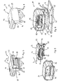
- the first connector or the device holder 10 are shown in more detail in FIGS. 2 to 6.
- the first connector 10 consists of three prefabricated components which can be plugged into one another, namely a first contact element receptacle 18 with contact elements designed as contact pins 20, a first shield 22 made as a one-piece stamped and bent part from a metal sheet and a first housing 24.
- the trained as a plastic injection molded part first contact element receptacle 18 has an L-shape with a running in a direction of insertion S 1 first leg 26 with an asymmetrical cross-section and a relative to this at an angle of 90 ° angled second leg 26 '.
- a first end face 28 of the first leg 26 is oriented orthogonal to the plug-in direction S 1 and a second end face 28 'of the second leg 26' orthogonal to the first end face 28.
- a resilient metal sheet first shield 22 is shown in Fig. 2 in an already partially bent state, and has a sleeve portion 34 which corresponds in shape to the corresponding portion of the first contact element receptacle 18.
- a substantially U-shaped foot member 36 with arranged on opposite sides forked feet 38, which together with the sleeve portion 34 an orthogonal to the insertion direction S 1 oriented insertion opening 40 encloses U-shaped.
- the contact element receptacle 18 in the first shield 22 can be inserted (see Fig .. 3).
- the sleeve portion 34 and in particular its interior have transversely to the direction of insertion on a cross section corresponding to the cross section of the contact element receiving transversely to the insertion direction S 1 , so that the contact element receptacle 18 closely fitting to the inner wall of the sleeve portion 34 is inserted into this.
- the foot part 36 also corresponds in shape to the shape of the corresponding portion of the first contact element receptacle 18, i. of the second leg 26 ', wherein the fork-shaped feet 38 are designed for mounting on the circuit carrier 12 in corresponding holes 48.
- the wing 42 is dimensioned such that by bending the wing 42 along a bending line orthogonal to the plug-in direction S 1, the insertion opening 40 is essentially coverable or closable by the wing 42 (see Fig .. 4).
- the wing 42 and the side parts 44 thereto are formed so that in the bent state, the lower edge is approximately aligned with the lower edge of the foot part 36 and the leg 26 '.
- On the side parts 44 further bent guide rails 50 are formed, which extend in the bent state in Fig. 4 parallel to the insertion direction S 1 .
- the first housing 24 is integrally formed as an injection molded part of a dimensionally stable plastic sleeve-like with an asymmetric, the cross section of the first shield 18 corresponding cross-section transverse to the insertion direction S 1 . It has for attachment to the circuit substrate 12 has two retaining pin 52 and a substantially U-shaped wall portion 54 which is formed so that it receives the foot portion 36 of the shield substantially form-fitting manner, and when mounted on the circuit substrate 12 on this with his lower edge is seated.
- a circumferential receiving groove 56 is formed for receiving a housing collar of the second connector 14. Furthermore, parallel to the plug-in direction Si, which runs parallel to the walls of the sleeve-like portion of the housing 24, retaining grooves 58 for receiving the guide rails 50 on the side parts 44 of the wing 42 of the first shield 22 are formed.
- the first contact element receptacle 18 in the first shield 22 is inserted.
- the wing 42 is oriented parallel to the plug-in direction S 1 in the assembled state.
- the part of the sleeve portion 34, which projects beyond the end face 28, now forms a collar 59 surrounding the plug-in ends 32, the edge of which protrudes beyond the plug-in ends 32 in the insertion direction S 1 .
- the wing 42 is bent over to the first contact element receptacle 18 until it is angled at an angle of approximately 90 ° relative to the insertion direction-S 1 at the edge of the foot portion 36 abuts (see Fig .. 4).
- the first contact element receptacle 18 is now secured against movements parallel to the plug-in direction S 1 by the bent wing 42 on the one hand and the wing section 42 opposite the wall portion of the foot part 36 on the other.
- the first contact element receptacle 18 including the plug-in ends 32 to the end faces of the legs 26 and 26 ' is substantially completely enclosed by the first shield 22.
- the unit thus formed is inserted into the first housing 24, wherein the guide rails 50 are inserted at the side parts 44 in the retaining grooves 58 in the first housing 24 become.
- These are designed such that, at least for assembly purposes, the unit of first contact element receptacle 18 and first shield 22 is connected to the housing 24 by means of a clamping fit.
- a bending of the wing 42 in a position parallel to the insertion direction S 1 is now blocked by the guide rails 50 held in the retaining grooves 58, so that the first contact element receptacle 18 is securely held in the first shield 22.
- the first housing 24 surrounds the sleeve portion 34 of the first shield 18 so that it is mechanically well protected.
- the unit thus formed can now be mounted on the circuit carrier 12, wherein the feet 38 are inserted into the holes 48, the retaining pin 52 in corresponding mounting holes 60 and the contacting ends 30 in contacting holes 62.
- the holding pins 52 are seated in the clamping seat in the mounting holes 60.
- the feet 38 serve both as a mechanical support for the first shield 22 and for contacting printed conductors on the circuit substrate 12.
- the very easy to manufacture first connector 10 in the form of a device holder is then very firmly held even with very large insertion forces on the circuit substrate 12.
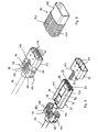
- the second contact element receptacle 64 is likewise designed as a plastic injection-molded part and has a flat cuboidal basic shape.
- the second contact element receptacle 64 are parallel to a direction of insertion S 2 of the second connector several, in the example six in a series of mutually parallel, channels for receiving contact elements 82 is formed.
- the contact elements 82 have on the plug side contact sockets and on a conductor side means for abutting cables 84 of the line 16 and for establishing a crimp connection with the cables 84.
- the second shield 66 consists of the two designed as stamped and bent parts shielding parts 68 and 70, which can be put together in a direction transverse to the insertion direction S 2 .
- the two shield parts 68 and 70 are substantially U-shaped so that they enclose the second contact element receptacle 64 after mating and abut against this.
- the first shield member 68 has, for connection to the second shielding member 70, two pairs of first tabs 88 and second tabs 90, each lowered from the outer surfaces.
- the second shielding member 70 has, in an L-shaped outer portion 92, opposed flat recessed portions 94 protruding parallel to its surface beyond the L-shaped portion 92. Breakthroughs 96 are furthermore punched out in the recessed regions 94, which roughly correspond in shape to the shape of the first tongues 88. At the opposite side of the insertion direction S 2 side of the openings 96 each support elements 98 are bent approximately orthogonal to the level of the recessed areas 94. Furthermore, a sixteenbiegbare clamp 100 is formed for contacting a not shown in the figures shielding of the line 16 at the opposite end of the insertion direction S 2 end face.
- the second shielding part 70 is formed, except for the clamp 100, symmetrically with respect to a plane parallel to the recessed region 94.
- the recessed areas 94 are lowered relative to the L-shaped portion 92 so far that the locking projections 86 of the second contact element receptacle 64 in the frontal portion of the L-shaped portion 92 are durable.
- the housing cap 78 is in two parts and composed of an upper part 102 and a lower part 104 and has a cuff 106 formed from corresponding sleeve portions of the upper and lower part for receiving the conduit 16.
- the housing cap 78 is substantially pot-shaped, wherein the pot walls are shaped so that they can receive the mating shield 66 partially and positively (see Fig. 9).
- the locking element 72 is also embodied sleeve-shaped as a plastic injection molded part and corresponds in shape substantially to the shape of the sleeve-shaped portion of the housing cap 78.
- stop elements 114 are formed, which serve on the one hand, the resilient, in the form of coil springs To hold elements 74 and act as a driving stop on the other.
- the actuating member 80 is also formed as an injection molded part made of plastic. It has the form of a sleeve which receives the locking element 72 and the housing cap 78 at least partially tight fitting.
- a front housing collar 118 in the direction of insertion S 2 has smooth walls and a cross-section such that it can be inserted in a form-fitting manner into the first housing 24 and in particular its receiving groove 56.
- a rear handle portion 120 seen in the direction of insertion S 2 symmetrical parallel to the insertion direction S 2 extending, opposite ends of the insertion direction S 2 open guide channels 122 are formed on opposite flat sides, in which the support members 98, the housing support members 112 and the stop members 114 are feasible.
- the two shielding parts 68 and 70 are pushed across the second contact element receptacle 64 transversely to the plugging direction S2, the second tongues 90 engaging under the L-shaped section 92 and edge sections of the recessed areas 94 in the first shielding part 68.
- the first tongues 88 snap into the apertures 96 and close them.
- the contact element receptacle 64 is now completely enclosed by the shield 66 except for its end faces, since the apertures 96 are covered by the first tongues 88.
- the contact element receptacle 64 with respect to the shield 66 is no longer displaceable, since the locking projections 86 engage in the acting as a locking element L-shaped portion 92.
- clamp 100 is bent around the exposed shield of the conduit 16 and contacted therewith (see Fig. 8).
- the exposed recessed areas 94 now form recesses 124 on opposite sides. At their end faces lying in the plug-in direction S 2 , the recesses 124 form limiting shoulders, respectively a securing protrusion 126 as securing elements complementary to the securing elements or snap hooks 46.
- the upper part 102 and the lower part 104 of the housing cap 78 are put together, wherein the conduit 16 is encompassed by the sleeve sections which form the sleeve 106. Injection of the line 16 is not necessary.
- the actuating member 80 is pushed onto the resulting unit and locked with the housing cap 78, so that the second connector 14 shown in FIG. 1 is formed.
- the second connector is inserted with the actuating member 80 in the first housing 24, wherein the non-symmetrical shape of the inner cross section of the housing 24 and the corresponding outer cross section of the actuating member 80 and the housing collar 118 accidental rotation is excluded.
- the housing collar 118 is designed so that it is in the receiving groove 56 in the housing 24 substantially form-fitting manner receivable.
- the mating ends 32 of the contact pins 20 are inserted into the contact elements 82 in the second contact element receptacle 64, wherein at the same time, favored by mutually bent edges on the front side of the second shield 66, in Figs. 10 to 15 only incomplete and schematically shown snap hook 46 of the second shield 66 are resiliently bent apart and thus stretched. They abut against the end face of the locking element 72 and push the locking element 72, which surrounds the shield 66 and is guided in the guide channel 118 with the stop element 114, from a locking position in which it covers the recesses 124 and the securing projections 126 against the plug-in direction S 1 to the housing cap 78 to.
- the resilient elements 84 are supported on the support elements 98 of the second shield 66.
- the locking element 72 Upon further insertion, the locking element 72 releases the securing projections 126 and the depression 124 at least partially, so that the snap-action hooks 46 can snap into the depressions 124 in a securing position behind the securing projections 126 (see Fig. 11). The locking element 72 has then reached the unlocking position.
- the housing collar 118 is inserted as far as possible into the receiving groove 56 in the first housing 24, wherein the handle portion 120 abuts in its connecting position on the end face of the first housing 24 and thus a further movement prevented in Caribbeansteckraum. Furthermore, the area in which the contact elements are plugged together, completely surrounded by the mated housings and thus protected.
- the actuating member 80 is moved by an opening movement opposite to the insertion direction S 2 on the housing cap 78 to an open position, wherein the run in the guide channels 122 stop elements 114 acting as driving stops 128 acting in the direction of insertion S 2 end walls 130 of the guide channels 122nd be taken as complementary attacks.
- the locking element 72 is moved from the locking position into the unlocking position.
- the depression 124 and in particular the securing projections 126 and the snap-action hooks 46 are partially released, so that they can be moved in a direction transverse to the insertion direction.
- the length or locking position of the locking element 72 is selected so that the actuating member 80 only over a predetermined distance, in the example about 6 mm, must be moved until the unlocking position is reached. This precludes, on the one hand, that an unlocking can take place in the event of a brief, random movement of the actuating part 80.
- the minimum force for unlocking can be easily adjusted, which is necessary to effect unlocking.
- the snap hooks 46 of the first shield 22 are pulled and spread apart by applying a corresponding force to the securing protrusions 126, for which the corresponding hook-shaped portions are bent substantially V-shaped, so that the securing protrusions 126 are guided on the respective legs of the hook-shaped portions ,
- the Snap hooks 46 no longer hinder the further pulling apart, so that the connectors can be completely separated.
Landscapes
- Details Of Connecting Devices For Male And Female Coupling (AREA)
- Connector Housings Or Holding Contact Members (AREA)
- Earth Drilling (AREA)
- Piezo-Electric Or Mechanical Vibrators, Or Delay Or Filter Circuits (AREA)
- Quick-Acting Or Multi-Walled Pipe Joints (AREA)
Claims (18)
- Connecteur (14) pour l'emboîtement avec un connecteur (10) complémentaire dans un sens d'enfichage, en particulier pour une utilisation dans un véhicule automobile, comprenant- un logement d'élément de contact (64) pour le logement d'un élément de contact (82), de préférence d'au moins deux éléments de contact (82),- un blindage (66) entourant au moins partiellement le logement d'élément de contact (64), le blindage (66) présentant au moins un élément de sécurité (126), de préférence un élément à encliquetage ou à cran d'arrêt, qui, lors de l'emboîtement du connecteur (14) avec un connecteur (10) complémentaire approprié, peut être déplacé par rapport à un élément de sécurité (46) complémentaire du connecteur (10) complémentaire, de préférence un élément à encliquetage ou à cran d'arrêt complémentaire, dans une position de sécurité par rapport à l'élément de sécurité complémentaire et au moyen duquel, dans la position de sécurité et par coopération avec l'élément de sécurité complémentaire, un déplacement relatif des connecteurs (10, 14) à partir de la position emboîtée peut être limité,- un boîtier (76) logeant au moins partiellement le logement d'élément de contact (64) et le blindage (66), et- un élément de verrouillage (72) pouvant être déplacé par rapport au logement d'élément de contact (64) entre une position de déverrouillage et une position de verrouillage, les éléments de sécurité du connecteur (14) et du connecteur (10) complémentaire pouvant être déplacés vers la position de sécurité et/ou à partir de celle-ci lorsque l'élément de verrouillage (72) est dans la position de déverrouillage et l'élément de verrouillage (72) dans la position de verrouillage verrouille les éléments de sécurité (46, 126) dans leur position de sécurité empêchant un déplacement à partir de la position de sécurité,caractérisé en ce que
le connecteur (14) est réalisé pour l'emboîtement avec un connecteur (10) complémentaire, qui présente une collerette (34) formée de préférence par un blindage (22),
et en ce que l'élément de verrouillage (72) est espacé du blindage (66) du connecteur de telle sorte que la collerette (34) périphérique du connecteur (10) complémentaire peut être logée au moins partiellement entre l'élément de verrouillage (72) et le blindage (66) du connecteur (14). - Connecteur selon la revendication 1,
caractérisé en ce que
le boîtier (76) est assemblé, en particulier emboîté et/ou regroupé, à partir d'au moins deux parties de boîtier (78, 80, 104, 106). - Connecteur selon la revendication 1,
caractérisé en ce que
le boîtier est conçu d'une seule pièce et comprend une partie en forme de douille, dans laquelle le blindage (66) est introduit avec le logement d'élément de contact (64). - Connecteur selon l'une quelconque des revendications précédentes,
caractérisé en ce que
le blindage (66) présente au moins deux parties de blindage (68, 70) pouvant être regroupées transversalement au sens d'enfichage, lesquelles sont réalisées de préférence sous la forme de parties pliées et estampées. - Connecteur selon la revendication 4,
caractérisé en ce que
le logement d'élément de contact (64) et le blindage (66) présentent des éléments de blocage (86, 92) coopérant et agencés transversalement au sens d'enfichage, qui bloquent un déplacement relatif entre le logement d'élément de contact (64) et le blindage (66) dans le sens d'enfichage et/ou dans le sens contraire au sens d'enfichage. - Connecteur selon l'une quelconque des revendications 1 à 3,
caractérisé en ce que
le blindage est conçu d'une seule pièce sous la forme de partie pliée et estampée. - Connecteur selon l'une quelconque des revendications précédentes,
caractérisé en ce que
le blindage présente une ailette pliée et recourbée en sens contraire du sens d'enfichage, qui ferme au moins partiellement une ouverture d'introduction dans le blindage, par laquelle le logement d'élément de contact peut être introduit dans le blindage. - Connecteur selon l'une quelconque des revendications précédentes,
caractérisé en ce que
le connecteur est conçu comme un logement d'appareil dans lequel, des contacts destinés à la liaison avec un support de circuit sont réalisés de préférence sur des côtés opposés du blindage. - Connecteur selon l'une quelconque des revendications précédentes,
caractérisé en ce que
le blindage présente (66) présente deux éléments de sécurité (126) conçus de préférence sur des côtés opposés du blindage (66). - Connecteur selon l'une quelconque des revendications précédentes,
caractérisé en ce que
l'élément de sécurité présente un crochet à encliquetage ou à cran d'arrêt élastique. - Connecteur selon l'une quelconque des revendications précédentes,
caractérisé en ce que
l'élément de sécurité présente une saillie de sécurité (126) derrière laquelle s'accroche en position de sécurité un crochet à encliquetage ou à cran d'arrêt (46) d'un connecteur (10) complémentaire emboîté avec le connecteur (14). - Connecteur selon la revendication 11,
caractérisé en ce que
le connecteur (14) est conçu avec un élément à encliquetage ou à cran d'arrêt (46) élastique pour l'emboîtement avec un connecteur (10) complémentaire. - Connecteur selon l'une quelconque des revendications 1 à 12,
caractérisé en ce que
l'élément de verrouillage (72) peut coulisser parallèlement au sens d'enfichage par rapport au blindage (66) et de préférence entoure le blindage (66) au moins en partie à la façon d'une douille. - Connecteur selon l'une quelconque des revendications 1 à 13,
caractérisé en ce que
il est prévu un élément (74) élastique, qui peut être serré dans la position de déverrouillage par le déplacement de l'élément de verrouillage (72) par rapport au connecteur (14) et au moyen de la force de rappel duquel l'élément de verrouillage (72) peut être déplacé dans la position de verrouillage. - Connecteur selon l'une quelconque des revendications 1 à 14,
caractérisé en ce que
l'élément de verrouillage (72) peut être déplacé de la position de verrouillage vers a position de déverrouillage par un mouvement d'ouverture d'une partie d'actionnement (80) du boîtier (76) depuis une position assemblée, dans laquelle le connecteur (14) est emboîté avec un connecteur (10) complémentaire, dans une position d'ouverture par rapport au logement d'élément de contact (64). - Connecteur selon la revendication 15,
caractérisé en ce que
l'élément de verrouillage (72) comporte une butée mobile (128), qui se plaque au moins pendant une partie du mouvement d'ouverture de la partie d'actionnement (80) contre une butée (130) complémentaire de la partie d'actionnement (80). - Connecteur selon l'une quelconque des revendications précédentes,
caractérisé en ce que
des éléments de contact (82) pouvant abriter un câble, ou réciproquement, sont disposés dans le logement d'élément de contact (64). - Système de connecteur comprenant un connecteur (14) selon l'une quelconque des revendications 1 à 17 et un connecteur (10) complémentaire et emboîtable avec celui-ci.
Priority Applications (1)
| Application Number | Priority Date | Filing Date | Title |
|---|---|---|---|
| AT05012056T ATE346404T1 (de) | 2003-06-03 | 2003-06-03 | Steckverbinder |
Applications Claiming Priority (1)
| Application Number | Priority Date | Filing Date | Title |
|---|---|---|---|
| EP03012603A EP1484822B1 (fr) | 2003-06-03 | 2003-06-03 | Connecteur |
Related Parent Applications (1)
| Application Number | Title | Priority Date | Filing Date |
|---|---|---|---|
| EP03012603A Division EP1484822B1 (fr) | 2003-06-03 | 2003-06-03 | Connecteur |
Publications (2)
| Publication Number | Publication Date |
|---|---|
| EP1585201A1 EP1585201A1 (fr) | 2005-10-12 |
| EP1585201B1 true EP1585201B1 (fr) | 2006-11-22 |
Family
ID=33155144
Family Applications (2)
| Application Number | Title | Priority Date | Filing Date |
|---|---|---|---|
| EP03012603A Expired - Lifetime EP1484822B1 (fr) | 2003-06-03 | 2003-06-03 | Connecteur |
| EP05012056A Expired - Lifetime EP1585201B1 (fr) | 2003-06-03 | 2003-06-03 | Connecteur |
Family Applications Before (1)
| Application Number | Title | Priority Date | Filing Date |
|---|---|---|---|
| EP03012603A Expired - Lifetime EP1484822B1 (fr) | 2003-06-03 | 2003-06-03 | Connecteur |
Country Status (4)
| Country | Link |
|---|---|
| US (1) | US7077703B2 (fr) |
| EP (2) | EP1484822B1 (fr) |
| AT (1) | ATE346403T1 (fr) |
| DE (2) | DE50305800D1 (fr) |
Families Citing this family (17)
| Publication number | Priority date | Publication date | Assignee | Title |
|---|---|---|---|---|
| IT1183345B (it) * | 1985-02-13 | 1987-10-22 | Montefluos Spa | Poliuretani fluorurati contenenti blocchi poliosiperfluoroalchilenici di migliorate caratteristiche meccaniche |
| US6719581B2 (en) * | 2002-07-25 | 2004-04-13 | Nippon Dics Co., Ltd. | Plug for speaker cables, and speaker terminal and speaker terminal system provided with them |
| FR2875037B1 (fr) * | 2004-09-07 | 2006-10-20 | Itt Mfg Enterprises Inc | Ensemble de connexion pour carte a puce comportant des moyens de protection contre la fraude |
| USD531577S1 (en) * | 2005-03-07 | 2006-11-07 | Cheng Uei Precision Industry Co., Ltd. | Receptacle connector |
| US7285004B1 (en) * | 2005-04-21 | 2007-10-23 | Yazaki North America, Inc. | USB locking connector system |
| US20080076289A1 (en) * | 2006-09-11 | 2008-03-27 | Yueh-Hua Hsu Huang | Structure of Connnectors |
| US7413446B1 (en) * | 2007-05-14 | 2008-08-19 | Fci Americas Technology, Inc. | Electrical connector module |
| TW201039498A (en) * | 2009-04-20 | 2010-11-01 | Innodisk Corp | SATA data connection device with raised reliability |
| CN201515098U (zh) | 2009-09-11 | 2010-06-23 | 上海莫仕连接器有限公司 | 电连接装置 |
| KR101666868B1 (ko) * | 2009-12-29 | 2016-10-19 | 한국단자공업 주식회사 | 유에스비이 소켓 |
| WO2011160971A1 (fr) * | 2010-06-23 | 2011-12-29 | Tyco Electronics France Sas | Connecteur électrique coudé doté d'une seconde ouverture de face de fiche et module de connecteur électrique doté de deux éléments de boîtier pourvus chacun d'au moins une extension d'isolation |
| US8804354B2 (en) | 2012-09-11 | 2014-08-12 | Apple Inc. | Load sharing device and I/O architecture against imparted abuse loads |
| US8804355B2 (en) * | 2012-09-11 | 2014-08-12 | Apple Inc. | Connector bracket |
| CN203225432U (zh) * | 2013-04-02 | 2013-10-02 | 富士康(昆山)电脑接插件有限公司 | 电连接器组件 |
| TWM482180U (zh) * | 2014-02-07 | 2014-07-11 | Wieson Technologies Co Ltd | 插頭連接器結構 |
| DE102019202444A1 (de) * | 2019-02-22 | 2020-08-27 | Zf Friedrichshafen Ag | Bestückungselement für einen Aktor |
| CN112366481A (zh) * | 2019-07-25 | 2021-02-12 | 富士康(昆山)电脑接插件有限公司 | 电连接器组合、插头连接器及插座连接器 |
Family Cites Families (20)
| Publication number | Priority date | Publication date | Assignee | Title |
|---|---|---|---|---|
| US4781623A (en) * | 1984-01-16 | 1988-11-01 | Stewart Stamping Corporation | Shielded plug and jack connector |
| US4797116A (en) * | 1987-01-26 | 1989-01-10 | Amp Incorporated | Electrical connector having a movable contact guide and lance-maintaining member |
| JPH0530307Y2 (fr) * | 1987-02-12 | 1993-08-03 | ||
| JPH01134373U (fr) * | 1988-03-07 | 1989-09-13 | ||
| JPH02150682U (fr) * | 1989-05-22 | 1990-12-27 | ||
| US5171161A (en) * | 1991-05-09 | 1992-12-15 | Molex Incorporated | Electrical connector assemblies |
| US5167516A (en) * | 1991-08-21 | 1992-12-01 | Foxconn International, Inc. | Connection with floating shield |
| US5244415A (en) * | 1992-02-07 | 1993-09-14 | Harbor Electronics, Inc. | Shielded electrical connector and cable |
| JP2595406Y2 (ja) * | 1992-03-25 | 1999-05-31 | ホシデン株式会社 | プラグ型多極コネクタ |
| US5545052A (en) * | 1992-08-19 | 1996-08-13 | Honda Tsushin Kogyo Kabushiki Kaisha | Electrical connector |
| JP2595011Y2 (ja) * | 1992-12-11 | 1999-05-24 | ホシデン株式会社 | ソケット型多極コネクタ |
| US5580268A (en) * | 1995-03-31 | 1996-12-03 | Molex Incorporated | Lockable electrical connector |
| JPH0963694A (ja) * | 1995-08-21 | 1997-03-07 | Honda Tsushin Kogyo Kk | ロック機構を有するコネクタ |
| JPH1167365A (ja) * | 1997-08-08 | 1999-03-09 | Molex Inc | 電気コネクタ |
| JP3355567B2 (ja) * | 1998-02-04 | 2002-12-09 | 住友電装株式会社 | 基板用コネクタ |
| TW540867U (en) * | 1998-12-31 | 2003-07-01 | Hon Hai Prec Ind Co Ltd | Cable connector |
| SG109416A1 (en) * | 1999-01-26 | 2005-03-30 | Molex Inc | Electrical connector with locking mechanism and metal spring |
| TW420418U (en) * | 1999-05-15 | 2001-01-21 | Hon Hai Prec Ind Co Ltd | Electrical cable connector |
| US6431887B1 (en) * | 2000-05-31 | 2002-08-13 | Tyco Electronics Corporation | Electrical connector assembly with an EMI shielded plug and grounding latch member |
| US6619976B2 (en) * | 2001-04-13 | 2003-09-16 | Hewlett-Packard Development Company, Lp. | Apparatus and method for cable connection retention |
-
2003
- 2003-06-03 DE DE50305800T patent/DE50305800D1/de not_active Expired - Fee Related
- 2003-06-03 DE DE50305747T patent/DE50305747D1/de not_active Expired - Fee Related
- 2003-06-03 EP EP03012603A patent/EP1484822B1/fr not_active Expired - Lifetime
- 2003-06-03 AT AT03012603T patent/ATE346403T1/de not_active IP Right Cessation
- 2003-06-03 EP EP05012056A patent/EP1585201B1/fr not_active Expired - Lifetime
-
2004
- 2004-05-27 US US10/855,152 patent/US7077703B2/en not_active Expired - Fee Related
Also Published As
| Publication number | Publication date |
|---|---|
| EP1484822B1 (fr) | 2006-11-22 |
| US20040248467A1 (en) | 2004-12-09 |
| DE50305800D1 (de) | 2007-01-04 |
| US7077703B2 (en) | 2006-07-18 |
| DE50305747D1 (de) | 2007-01-04 |
| EP1484822A1 (fr) | 2004-12-08 |
| EP1585201A1 (fr) | 2005-10-12 |
| ATE346403T1 (de) | 2006-12-15 |
Similar Documents
| Publication | Publication Date | Title |
|---|---|---|
| EP1585201B1 (fr) | Connecteur | |
| DE69822393T2 (de) | Elektrischer Steckverbinder für flexible Flachband-Schaltkreise | |
| DE19500959C2 (de) | Elektrischer Steckverbinder | |
| DE60027611T2 (de) | Kabelverbinder mit gesteuerter Impedanz | |
| DE69204439T2 (de) | Elektrischer Steckverbinder zum Aufnehmen einer Leiterplatte. | |
| DE69207217T2 (de) | Abgeschirmte elektrische Verbinderanordnung | |
| EP1207588B1 (fr) | Connecteur électrique pour cable plat ou circuit imprimé flexible | |
| DE102016120063B4 (de) | Steckverbindung | |
| DE4013189C2 (de) | Elektrische Steckverbindungsvorrichtung | |
| DE102009056517B4 (de) | Steckverbinderanordnung mit erstem und zweitem Stecker und Gegenstecker | |
| DE3437988A1 (de) | Elektrisches schaltgeraet | |
| DE19813458A1 (de) | Elektrischer Verbinder | |
| DE10119695B4 (de) | Steckverbinder für elektronische Bauelemente | |
| DE4119685C2 (de) | Elektrische Steckverbindungsvorrichtung | |
| DE10393763T5 (de) | Schaltungsplattenverbinder mit einstückiger dielektrischer Abdeckung | |
| DE102012104857B4 (de) | Elektrische Steckverbindung | |
| EP0819325A1 (fr) | Connecteur a fiches pour cable plat | |
| DE4016114C2 (de) | Elektrischer Mehrkontakt-Verbinder, der eine geringe Verbindungs- und Trennkraft erfordert | |
| DE69013734T2 (de) | Elektrischer Verbinder. | |
| EP3782235B1 (fr) | Connecteur direct | |
| DE69803818T2 (de) | Verbinderverriegelung | |
| EP1139493A2 (fr) | Connecteur électrique pour le raccordement de câbles à un appareil | |
| EP0831559A2 (fr) | Connecteur à fiche | |
| DE102021129010A1 (de) | Kontaktträgereinrichtung, Anschlussvorrichtung, Betätiger, Steckverbindereinsatz und Montageverfahren sowie Kabelanschlusssystem | |
| EP1269579B1 (fr) | Connecteur a fiches pour conducteurs a bande plate |
Legal Events
| Date | Code | Title | Description |
|---|---|---|---|
| PUAI | Public reference made under article 153(3) epc to a published international application that has entered the european phase |
Free format text: ORIGINAL CODE: 0009012 |
|
| AC | Divisional application: reference to earlier application |
Ref document number: 1484822 Country of ref document: EP Kind code of ref document: P |
|
| AK | Designated contracting states |
Kind code of ref document: A1 Designated state(s): AT BE BG CH CY CZ DE DK EE ES FI FR GB GR HU IE IT LI LU MC NL PT RO SE SI SK TR |
|
| AX | Request for extension of the european patent |
Extension state: AL LT LV MK |
|
| 17P | Request for examination filed |
Effective date: 20051118 |
|
| AKX | Designation fees paid |
Designated state(s): AT BE BG CH CY CZ DE DK EE ES FI FR GB GR HU IE IT LI LU MC NL PT RO SE SI SK TR |
|
| GRAP | Despatch of communication of intention to grant a patent |
Free format text: ORIGINAL CODE: EPIDOSNIGR1 |
|
| GRAS | Grant fee paid |
Free format text: ORIGINAL CODE: EPIDOSNIGR3 |
|
| GRAA | (expected) grant |
Free format text: ORIGINAL CODE: 0009210 |
|
| AC | Divisional application: reference to earlier application |
Ref document number: 1484822 Country of ref document: EP Kind code of ref document: P |
|
| AK | Designated contracting states |
Kind code of ref document: B1 Designated state(s): AT BE BG CH CY CZ DE DK EE ES FI FR GB GR HU IE IT LI LU MC NL PT RO SE SI SK TR |
|
| PG25 | Lapsed in a contracting state [announced via postgrant information from national office to epo] |
Ref country code: FI Free format text: LAPSE BECAUSE OF FAILURE TO SUBMIT A TRANSLATION OF THE DESCRIPTION OR TO PAY THE FEE WITHIN THE PRESCRIBED TIME-LIMIT Effective date: 20061122 Ref country code: IE Free format text: LAPSE BECAUSE OF FAILURE TO SUBMIT A TRANSLATION OF THE DESCRIPTION OR TO PAY THE FEE WITHIN THE PRESCRIBED TIME-LIMIT Effective date: 20061122 Ref country code: RO Free format text: LAPSE BECAUSE OF FAILURE TO SUBMIT A TRANSLATION OF THE DESCRIPTION OR TO PAY THE FEE WITHIN THE PRESCRIBED TIME-LIMIT Effective date: 20061122 Ref country code: NL Free format text: LAPSE BECAUSE OF FAILURE TO SUBMIT A TRANSLATION OF THE DESCRIPTION OR TO PAY THE FEE WITHIN THE PRESCRIBED TIME-LIMIT Effective date: 20061122 Ref country code: SK Free format text: LAPSE BECAUSE OF FAILURE TO SUBMIT A TRANSLATION OF THE DESCRIPTION OR TO PAY THE FEE WITHIN THE PRESCRIBED TIME-LIMIT Effective date: 20061122 Ref country code: SI Free format text: LAPSE BECAUSE OF FAILURE TO SUBMIT A TRANSLATION OF THE DESCRIPTION OR TO PAY THE FEE WITHIN THE PRESCRIBED TIME-LIMIT Effective date: 20061122 Ref country code: CZ Free format text: LAPSE BECAUSE OF FAILURE TO SUBMIT A TRANSLATION OF THE DESCRIPTION OR TO PAY THE FEE WITHIN THE PRESCRIBED TIME-LIMIT Effective date: 20061122 |
|
| REG | Reference to a national code |
Ref country code: GB Ref legal event code: FG4D Free format text: NOT ENGLISH |
|
| REG | Reference to a national code |
Ref country code: CH Ref legal event code: EP |
|
| REG | Reference to a national code |
Ref country code: IE Ref legal event code: FG4D Free format text: LANGUAGE OF EP DOCUMENT: GERMAN |
|
| REF | Corresponds to: |
Ref document number: 50305800 Country of ref document: DE Date of ref document: 20070104 Kind code of ref document: P |
|
| PG25 | Lapsed in a contracting state [announced via postgrant information from national office to epo] |
Ref country code: SE Free format text: LAPSE BECAUSE OF FAILURE TO SUBMIT A TRANSLATION OF THE DESCRIPTION OR TO PAY THE FEE WITHIN THE PRESCRIBED TIME-LIMIT Effective date: 20070222 Ref country code: BG Free format text: LAPSE BECAUSE OF FAILURE TO SUBMIT A TRANSLATION OF THE DESCRIPTION OR TO PAY THE FEE WITHIN THE PRESCRIBED TIME-LIMIT Effective date: 20070222 Ref country code: DK Free format text: LAPSE BECAUSE OF FAILURE TO SUBMIT A TRANSLATION OF THE DESCRIPTION OR TO PAY THE FEE WITHIN THE PRESCRIBED TIME-LIMIT Effective date: 20070222 |
|
| PG25 | Lapsed in a contracting state [announced via postgrant information from national office to epo] |
Ref country code: ES Free format text: LAPSE BECAUSE OF FAILURE TO SUBMIT A TRANSLATION OF THE DESCRIPTION OR TO PAY THE FEE WITHIN THE PRESCRIBED TIME-LIMIT Effective date: 20070305 |
|
| PG25 | Lapsed in a contracting state [announced via postgrant information from national office to epo] |
Ref country code: PT Free format text: LAPSE BECAUSE OF FAILURE TO SUBMIT A TRANSLATION OF THE DESCRIPTION OR TO PAY THE FEE WITHIN THE PRESCRIBED TIME-LIMIT Effective date: 20070423 |
|
| NLV1 | Nl: lapsed or annulled due to failure to fulfill the requirements of art. 29p and 29m of the patents act | ||
| ET | Fr: translation filed | ||
| GBV | Gb: ep patent (uk) treated as always having been void in accordance with gb section 77(7)/1977 [no translation filed] |
Effective date: 20061122 |
|
| REG | Reference to a national code |
Ref country code: IE Ref legal event code: FD4D |
|
| PLBE | No opposition filed within time limit |
Free format text: ORIGINAL CODE: 0009261 |
|
| STAA | Information on the status of an ep patent application or granted ep patent |
Free format text: STATUS: NO OPPOSITION FILED WITHIN TIME LIMIT |
|
| 26N | No opposition filed |
Effective date: 20070823 |
|
| PG25 | Lapsed in a contracting state [announced via postgrant information from national office to epo] |
Ref country code: GB Free format text: LAPSE BECAUSE OF FAILURE TO SUBMIT A TRANSLATION OF THE DESCRIPTION OR TO PAY THE FEE WITHIN THE PRESCRIBED TIME-LIMIT Effective date: 20061122 |
|
| BERE | Be: lapsed |
Owner name: DELPHI TECHNOLOGIES, INC. Effective date: 20070630 |
|
| PG25 | Lapsed in a contracting state [announced via postgrant information from national office to epo] |
Ref country code: MC Free format text: LAPSE BECAUSE OF NON-PAYMENT OF DUE FEES Effective date: 20070630 |
|
| REG | Reference to a national code |
Ref country code: CH Ref legal event code: PL |
|
| PG25 | Lapsed in a contracting state [announced via postgrant information from national office to epo] |
Ref country code: BE Free format text: LAPSE BECAUSE OF NON-PAYMENT OF DUE FEES Effective date: 20070630 |
|
| PG25 | Lapsed in a contracting state [announced via postgrant information from national office to epo] |
Ref country code: CH Free format text: LAPSE BECAUSE OF NON-PAYMENT OF DUE FEES Effective date: 20070630 Ref country code: LI Free format text: LAPSE BECAUSE OF NON-PAYMENT OF DUE FEES Effective date: 20070630 Ref country code: GR Free format text: LAPSE BECAUSE OF FAILURE TO SUBMIT A TRANSLATION OF THE DESCRIPTION OR TO PAY THE FEE WITHIN THE PRESCRIBED TIME-LIMIT Effective date: 20070223 |
|
| PG25 | Lapsed in a contracting state [announced via postgrant information from national office to epo] |
Ref country code: AT Free format text: LAPSE BECAUSE OF NON-PAYMENT OF DUE FEES Effective date: 20070603 |
|
| PGFP | Annual fee paid to national office [announced via postgrant information from national office to epo] |
Ref country code: IT Payment date: 20080624 Year of fee payment: 6 |
|
| PGFP | Annual fee paid to national office [announced via postgrant information from national office to epo] |
Ref country code: DE Payment date: 20080612 Year of fee payment: 6 |
|
| PGFP | Annual fee paid to national office [announced via postgrant information from national office to epo] |
Ref country code: FR Payment date: 20080617 Year of fee payment: 6 |
|
| PG25 | Lapsed in a contracting state [announced via postgrant information from national office to epo] |
Ref country code: EE Free format text: LAPSE BECAUSE OF FAILURE TO SUBMIT A TRANSLATION OF THE DESCRIPTION OR TO PAY THE FEE WITHIN THE PRESCRIBED TIME-LIMIT Effective date: 20061122 |
|
| PG25 | Lapsed in a contracting state [announced via postgrant information from national office to epo] |
Ref country code: CY Free format text: LAPSE BECAUSE OF FAILURE TO SUBMIT A TRANSLATION OF THE DESCRIPTION OR TO PAY THE FEE WITHIN THE PRESCRIBED TIME-LIMIT Effective date: 20061122 Ref country code: LU Free format text: LAPSE BECAUSE OF NON-PAYMENT OF DUE FEES Effective date: 20070603 |
|
| PG25 | Lapsed in a contracting state [announced via postgrant information from national office to epo] |
Ref country code: HU Free format text: LAPSE BECAUSE OF FAILURE TO SUBMIT A TRANSLATION OF THE DESCRIPTION OR TO PAY THE FEE WITHIN THE PRESCRIBED TIME-LIMIT Effective date: 20070523 Ref country code: TR Free format text: LAPSE BECAUSE OF FAILURE TO SUBMIT A TRANSLATION OF THE DESCRIPTION OR TO PAY THE FEE WITHIN THE PRESCRIBED TIME-LIMIT Effective date: 20061122 |
|
| REG | Reference to a national code |
Ref country code: FR Ref legal event code: ST Effective date: 20100226 |
|
| PG25 | Lapsed in a contracting state [announced via postgrant information from national office to epo] |
Ref country code: FR Free format text: LAPSE BECAUSE OF NON-PAYMENT OF DUE FEES Effective date: 20090630 |
|
| PG25 | Lapsed in a contracting state [announced via postgrant information from national office to epo] |
Ref country code: DE Free format text: LAPSE BECAUSE OF NON-PAYMENT OF DUE FEES Effective date: 20100101 |
|
| PG25 | Lapsed in a contracting state [announced via postgrant information from national office to epo] |
Ref country code: IT Free format text: LAPSE BECAUSE OF NON-PAYMENT OF DUE FEES Effective date: 20090603 |