EP1585196A1 - Elktrische und mechanische Verbindung - Google Patents
Elktrische und mechanische Verbindung Download PDFInfo
- Publication number
- EP1585196A1 EP1585196A1 EP05006209A EP05006209A EP1585196A1 EP 1585196 A1 EP1585196 A1 EP 1585196A1 EP 05006209 A EP05006209 A EP 05006209A EP 05006209 A EP05006209 A EP 05006209A EP 1585196 A1 EP1585196 A1 EP 1585196A1
- Authority
- EP
- European Patent Office
- Prior art keywords
- connecting arrangement
- cable
- metal sleeve
- arrangement according
- insulating
- Prior art date
- Legal status (The legal status is an assumption and is not a legal conclusion. Google has not performed a legal analysis and makes no representation as to the accuracy of the status listed.)
- Withdrawn
Links
- 239000002184 metal Substances 0.000 claims abstract description 30
- 238000002788 crimping Methods 0.000 claims description 18
- 238000007493 shaping process Methods 0.000 claims description 3
- 238000007789 sealing Methods 0.000 claims description 2
- 229910001220 stainless steel Inorganic materials 0.000 claims description 2
- 239000010935 stainless steel Substances 0.000 claims description 2
- 239000011324 bead Substances 0.000 description 3
- 238000009413 insulation Methods 0.000 description 3
- 230000001681 protective effect Effects 0.000 description 3
- 239000000463 material Substances 0.000 description 2
- 230000002411 adverse Effects 0.000 description 1
- 230000004323 axial length Effects 0.000 description 1
- 238000005452 bending Methods 0.000 description 1
- 238000004519 manufacturing process Methods 0.000 description 1
- 238000000034 method Methods 0.000 description 1
- 238000000926 separation method Methods 0.000 description 1
Images


Classifications
-
- H—ELECTRICITY
- H01—ELECTRIC ELEMENTS
- H01R—ELECTRICALLY-CONDUCTIVE CONNECTIONS; STRUCTURAL ASSOCIATIONS OF A PLURALITY OF MUTUALLY-INSULATED ELECTRICAL CONNECTING ELEMENTS; COUPLING DEVICES; CURRENT COLLECTORS
- H01R13/00—Details of coupling devices of the kinds covered by groups H01R12/70 or H01R24/00 - H01R33/00
- H01R13/58—Means for relieving strain on wire connection, e.g. cord grip, for avoiding loosening of connections between wires and terminals within a coupling device terminating a cable
- H01R13/5804—Means for relieving strain on wire connection, e.g. cord grip, for avoiding loosening of connections between wires and terminals within a coupling device terminating a cable comprising a separate cable clamping part
- H01R13/5808—Means for relieving strain on wire connection, e.g. cord grip, for avoiding loosening of connections between wires and terminals within a coupling device terminating a cable comprising a separate cable clamping part formed by a metallic element crimped around the cable
-
- H—ELECTRICITY
- H01—ELECTRIC ELEMENTS
- H01R—ELECTRICALLY-CONDUCTIVE CONNECTIONS; STRUCTURAL ASSOCIATIONS OF A PLURALITY OF MUTUALLY-INSULATED ELECTRICAL CONNECTING ELEMENTS; COUPLING DEVICES; CURRENT COLLECTORS
- H01R13/00—Details of coupling devices of the kinds covered by groups H01R12/70 or H01R24/00 - H01R33/00
- H01R13/46—Bases; Cases
- H01R13/52—Dustproof, splashproof, drip-proof, waterproof, or flameproof cases
- H01R13/5205—Sealing means between cable and housing, e.g. grommet
Definitions
- the present invention relates to an electrical and mechanical connecting arrangement comprising a preferably multi-core cable and a cylindrical plug connector part in the form of a plug or a socket, in accordance with the preamble of claim 1.
- the plug connector part is held with its rear, hollow end, which is remote from the plugging region, on a radiofrequency cable by means of a crimped connection.
- the front end of the plug connector part bears an insulating part about a socket or plug contact and, on the outside, a shielding contact.
- the manner in which the plugging region is fixed to the plug connector part is not described.
- the individual components of the plugging region are generally connected to one another and to a hollow housing, in whose rear end the cable is inserted, by means of screw fittings and/or latching connections.
- Such connections are relatively complex in terms of production and assembly. In addition, such connections require a relatively large amount of space.
- the measures according to the invention make possible a protective housing connection which is very simple in design terms and can be assembled in a simple manner even on the end user's premises.
- the connecting arrangement is assembled in a simple manner by crimping the metal sleeve, which is in the form of a protective housing, at both of its ends, i.e. not only for the purpose of connecting it to the completely insulated end of the cable, but also to the plugging region or to its insulating part.
- this protective-housing or metal-sleeve connection makes it possible to achieve both an interlocking connection which is thus also mechanically resistant to tensile stress, and a connection which is absolutely moisture-tight.
- the features according to claim 4 make it possible to achieve a situation in which the size of the material deformation is limited in certain regions without the quality of the crimping connection being adversely affected.
- the features according to claim 5 are expediently provided when the tool for producing the crimping connection comprises two half-shells, with the result that a material deformation on the metal sleeve in the region of the tool halves which lie next to one another is limited to a minimum and, as a result, no axial deformation takes place.
- the features according to claim 6 are provided, which makes it possible for even the shielding in the case of a shielded cable to be taken on in a simple manner by the metal sleeve and possibly transferred to the continuing cable. As a result, both the mechanical and an electrical connection can be produced in the same manner.
- the features according to one or more of claims 7 to 9 are expediently provided.
- the features according to claim 10 and/or 11 ensure a reliable grip and a contribution to miniaturization, and the features according to claim 12 ensure safe handling when producing a plug connection and prevent the cable from being bent.
- the present invention also relates to a tool for producing a crimping connection on an electrical and mechanical connecting arrangement of the abovementioned type, as is described by the features according to claim 13.
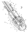
- the essentially cylindrical connecting arrangement 10 illustrated in figures 1 and 2 serves the purpose of mechanically and possibly electrically, for electromagnetic shielding, connecting a multi-core cable 11 to a plugging region 13 of a plug connector part 14, the individual cores 12 of the cable 11 being connected to the plugging region 13 separately.
- Figure 1 shows the cable 11 with in this case, for example, five cores 12, which are surrounded in each case individually and together as a bundle in their region from which the insulation has not been stripped by an insulating sheath 15 or 16.
- the plug connector part 14 has a two-part insulating body 20, whose rear bushing part 17 in this case accommodates, for example, plug contacts 18, to which the ends, from which the insulation has been stripped, of the individual cores 12 are fixedly connected in a suitable manner, for example by crimping.
- the plug contacts 18 are accommodated in the bushing part 17 such that they cannot be displaced axially, protrude with their front ends 19 beyond the bushing part 17 and are located within an insulating sleeve 21, which can be axially latched to the bushing part 17, of the insulating body 20 (figure 2). It goes without saying that such an insulating body 20 may instead also be provided with socket contacts.
- the two-part insulating body 20 is surrounded by a metallic, stepped connecting sleeve 22, which can be provided in a manner not illustrated in its front region having a smaller diameter with a metric outer thread or bayonet connection part for the mechanical connection to a socket/plug connector part on, for example, a device housing.
- the connecting sleeve 22 bears axially with its front end face 27 on a shoulder 28 of the insulating sleeve 21.
- the region of the connector sleeve 22 which has a greater diameter is provided on the side of the outer circumference with a knurl having a good grip.
- the bushing part 17 of the insulating body 20 is provided at its end region, which accommodates the connecting region of plug contacts 18 and cores 12, with two axially spaced-apart annular grooves 23 and 24, in which in each case an O-ring 25 or 26 is inserted.
- the two O-rings 25, 26 are replaced by a sealing collar provided with a corresponding axial extent.
- the rear end, which faces the cable 11, of the metal sleeve 30 is provided with a raised annular flange 31, whereas the front end, which faces the plugging region 13, of the metal sleeve 30 is provided with two annular attachments or beads 32 and 33 which are directed radially outwards.
- the metal sleeve 30 passes conically from a region having a smaller diameter and surrounding the cable 11 to a region having a larger diameter, into which the bushing part 17 of the insulating body 20 fits, and over which the region having the larger diameter of the connector sleeve 22 fits.
- the cable 11 is provided with a shielding braid 35, which, once the insulating sheath 16 is exposed, comes to lie on a metallic cup-shaped sleeve 34, which is pushed over the insulating sheath 16, such that it is turned back over a certain axial length.
- the connecting arrangement 10 is provided with a metallic, annular spring basket 36, which is accommodated between the two annular beads 32 and 33 on the side of the outer circumference on the metal sleeve 30.
- the metal sleeve 30 acts as a protective housing and, in the exemplary embodiment, also acts as a shielding housing which provides, in a simple and rapid manner, a mechanically fixed connection and, in the exemplary embodiment, also an electrical shielding connection between the cable 11 and the plugging region 13 or its insulating body 20 or its metallic connector sleeve 22.
- the cores 12 are connected to the plug contacts 18, and said plug contacts 18 are inserted in a latching manner in the bushing part 17 of the insulating body 20.
- the two O-rings 25 and 26 are fitted over the insulating body 20, and the insulating sleeve 21 is plugged onto the bushing part 17 in a latching manner, and the connector sleeve 22, which has already been threaded on, is fitted over the insulating sleeve 21 up to its annular shoulder 28.
- the metal sleeve 30 is fitted with the spring basket 36, which is fitted between the two annular beads 32 and 33, over the bushing part 17 provided with the O-rings 25, 26 and under the rear part, having a larger diameter, of the connector sleeve 22, the metallic spring basket 36 bearing with resilient prestress on the inner circumference of this part of the metallic connector sleeve 22. This results in a both electrical and mechanically frictional connection between the metal sleeve 30 and the connector sleeve 22.
- the first crimping connection 37 is made for the purpose of connecting the metal sleeve 30 to the insulating body 20 such that, in the region of the annular groove 23, which protrudes axially from the connector sleeve 22 and is fitted with the O-ring 25, in the bushing part 17, the metal sleeve 30 is pushed in on the circumference side, as a result of which the deformation 47, which protrudes radially inwards, deforms the O-ring 25 and partially engages in the annular groove 23.
- a second crimping connection 39 is made via an annular region of the metal sleeve 30 close to the annular flange 31 acting so as to protect the cable from bending such that the deformation 49, which protrudes radially inwards, compresses the insulating sheath 16 of the cable 11, as a result of which a connection can likewise be achieved which is moisture-tight and is mechanically resistant to tensile stress and is fixed against rotation.
- a third crimping connection 38 is made such that the deformation 48, which protrudes radially inwards, of the metal sleeve 30 clamps onto the shielding braid 35 on the circumference side, with the result that the metal sleeve 30 takes on the electromagnetic shielding of the cable cores 12, from which the insulation has been stripped, and the connection of said cores 12 to the plug contacts 18 in the insulating body 20, and, as mentioned, transfers the shielding onto the connector sleeve 22 and over said connector sleeve 22, uninterrupted, onto a further plug connector part.
- the bead-like deformations 47, 48, 49, which protrude radially inwards, of the crimping connections 37 to 39 are of identical design, i.e. the height of the deformations 47 to 49, which protrude radially inwards, is the same over the entire inner circumference.
- the deformations 47 to 49 of the crimping connections 37 to 39 are such that they have a maximum height or a minimum height at in each case two diametrically opposite regions.
- the deformations 47 to 49 are, with respect to their height (radial dimension), in the form of a sickle, when viewed in the axial direction, such that they extend constantly from a height close to or equal to zero over a maximum height again to a height close to or equal to zero.
- a crimping tool 40 which is illustrated schematically and only partially in figure 3, and which comprises two half-shells 41, each half-shell 41 having on the inside, when viewed in the circumferential direction, a shaping projection 42, which points radially inwards, and whose spacing, extending radially inwards, from the inner circumference face 43 of the tool half-shell 41 extends from a value close to or equal to zero over a maximum value again to a value close to or equal to zero, i.e. is in the form of a sickle when viewed axially.
- This configuration of the two tool half-shells 41 has the advantage that at the point where the two tool half-shells 41 meet one another radially, i.e. in the separation plane, no deformation of the metal sleeve 30 is brought about during the crimping operation in the axial direction.
- a structurally very small connecting apparatus 10 which has, for example, a maximum diameter of approximately 15 mm and a length from the end of the closure sleeve 21 to the remote end 31 of the metal sleeve 30 of approximately 55 mm.
- this connecting arrangement can also be used in the case of single-core cables and, in this case, in particular in the case of coaxial cables.
Landscapes
- Details Of Connecting Devices For Male And Female Coupling (AREA)
Applications Claiming Priority (2)
| Application Number | Priority Date | Filing Date | Title |
|---|---|---|---|
| DE102004018430 | 2004-04-06 | ||
| DE102004018430A DE102004018430A1 (de) | 2004-04-06 | 2004-04-06 | Elektrische und mechanische Verbindungsanordnung |
Publications (1)
| Publication Number | Publication Date |
|---|---|
| EP1585196A1 true EP1585196A1 (de) | 2005-10-12 |
Family
ID=34895587
Family Applications (1)
| Application Number | Title | Priority Date | Filing Date |
|---|---|---|---|
| EP05006209A Withdrawn EP1585196A1 (de) | 2004-04-06 | 2005-03-22 | Elktrische und mechanische Verbindung |
Country Status (3)
| Country | Link |
|---|---|
| US (1) | US7101223B2 (de) |
| EP (1) | EP1585196A1 (de) |
| DE (1) | DE102004018430A1 (de) |
Cited By (1)
| Publication number | Priority date | Publication date | Assignee | Title |
|---|---|---|---|---|
| CN101599608B (zh) * | 2008-06-02 | 2011-09-28 | 中航光电科技股份有限公司 | 一种短接装置及具有该装置的多芯插座 |
Families Citing this family (19)
| Publication number | Priority date | Publication date | Assignee | Title |
|---|---|---|---|---|
| JP4527019B2 (ja) * | 2005-07-13 | 2010-08-18 | 住友電装株式会社 | シールドコネクタ |
| US7390209B2 (en) * | 2006-02-22 | 2008-06-24 | Wealleys Technologies Co., Ltd. | Water-proof electric connector module |
| JP2008108675A (ja) * | 2006-10-27 | 2008-05-08 | Toshiba Corp | プラグ |
| US7534138B1 (en) | 2007-12-13 | 2009-05-19 | Delphi Technologies, Inc. | Electrical cable shielding terminal |
| JP5003583B2 (ja) * | 2008-04-25 | 2012-08-15 | オムロン株式会社 | コネクタ |
| US20100029113A1 (en) * | 2008-07-30 | 2010-02-04 | Smith Iii Robert L | Cable connector assembly |
| JP2010061891A (ja) * | 2008-09-02 | 2010-03-18 | Hitachi Cable Ltd | コネクタ |
| US8282138B2 (en) * | 2008-12-18 | 2012-10-09 | Rostra Tool Company | Crimp ring |
| CN102031937B (zh) * | 2009-09-30 | 2013-06-05 | 西安威尔罗根能源科技有限公司 | 一种免维护、防松动的绝缘短节 |
| JP5791712B2 (ja) | 2010-06-16 | 2015-10-07 | フェデラル−モーグル パワートレイン インコーポレイテッドFederal−Mogul Powertrain, Inc. | Emiコネクタフェルールおよびそれとのアセンブリ組合せ |
| US9293858B2 (en) * | 2014-05-26 | 2016-03-22 | Bren-Tronics, Inc. | Screw down connector |
| US9465183B2 (en) | 2014-05-30 | 2016-10-11 | Commscope Technologies Llc | Metal armored break-out cable assembly with grounding feature |
| EP3203586B1 (de) * | 2016-02-02 | 2020-07-22 | Yazaki Europe Ltd | Elektrischer steckverbinder |
| US9680268B1 (en) * | 2016-05-18 | 2017-06-13 | Itt Manufacturing Enterprises Llc | Genderless electrical connectors |
| CN206806628U (zh) * | 2017-03-22 | 2017-12-26 | 泰科电子(上海)有限公司 | 连接器 |
| US10985493B1 (en) * | 2019-10-04 | 2021-04-20 | R.A. Phillips Industries, Inc. | Electrical connector |
| KR102859461B1 (ko) * | 2020-09-09 | 2025-09-16 | 한국단자공업 주식회사 | 케이블용 커넥터 |
| DE102023118280A1 (de) * | 2023-07-11 | 2025-01-16 | Robert Karst Gmbh & Co. Kg. | Zusammenbau eines Steckverbinders und eines Koaxialkabels sowie Verfahren zur Herstellung |
| CN118630511B (zh) * | 2024-07-05 | 2025-03-11 | 惠州奥华智能科技有限公司 | 一种过孔连接器及其安装结构 |
Citations (6)
| Publication number | Priority date | Publication date | Assignee | Title |
|---|---|---|---|---|
| DE964291C (de) * | 1953-03-31 | 1957-05-23 | Kalart Company Inc | Zweiadriges Verbindungskabel fuer Blitzleuchten |
| FR1448436A (fr) * | 1964-09-22 | 1966-08-05 | Amp Inc | Fiche à broche coaxiale |
| US4897050A (en) * | 1989-03-30 | 1990-01-30 | Ntt, Inc. | Method and apparatus for making coaxial couplings |
| US5499934A (en) * | 1993-05-27 | 1996-03-19 | Cabel-Con, Inc. | Hexagonal crimp connector |
| US6250963B1 (en) * | 1999-08-30 | 2001-06-26 | Osram Sylvania Inc. | Connector shell, connector assembly and method of fabricating same |
| US20020119699A1 (en) * | 2001-02-28 | 2002-08-29 | Harting Automotive Gmbh & Co. Kg | Plug connector |
Family Cites Families (15)
| Publication number | Priority date | Publication date | Assignee | Title |
|---|---|---|---|---|
| US3539976A (en) * | 1968-01-04 | 1970-11-10 | Amp Inc | Coaxial connector with controlled characteristic impedance |
| US4634208A (en) * | 1983-01-31 | 1987-01-06 | Amp Incorporated | Electrical plug connector and method of terminating a cable therewith |
| US4583809A (en) * | 1984-04-02 | 1986-04-22 | Allied Corporation | Electrical connector assembly having means for EMI shielding |
| US4614398A (en) * | 1984-12-21 | 1986-09-30 | Simmonds Precision | Shielded cable terminal connection |
| US4799902A (en) * | 1987-08-19 | 1989-01-24 | Amp Incorporated | Triaxial electrical cable connector |
| US5083943A (en) * | 1989-11-16 | 1992-01-28 | Amphenol Corporation | Catv environmental f-connector |
| DE9007300U1 (de) * | 1990-05-11 | 1991-04-11 | Richard Hirschmann GmbH & Co, 7300 Esslingen | Steckverbinder |
| US5102351A (en) * | 1990-11-29 | 1992-04-07 | The United States Of America As Represented By The Secretary Of The Air Force | Shielded electric cable and harness with strain relief |
| US5888097A (en) * | 1997-02-13 | 1999-03-30 | Harco Laboratories, Inc. | Backshell assembly for repairable cable assembly |
| DE19726005A1 (de) * | 1997-06-19 | 1999-02-04 | Itt Mfg Enterprises Inc | Endgehäuse |
| US5879191A (en) * | 1997-12-01 | 1999-03-09 | Gilbert Engineering Co, Inc. | Zip-grip coaxial cable F-connector |
| US5997350A (en) * | 1998-06-08 | 1999-12-07 | Gilbert Engineering Co., Inc. | F-connector with deformable body and compression ring |
| US6857902B2 (en) * | 2001-02-21 | 2005-02-22 | I F M Electronics Gmbh | Proximity switch and a cable terminal part unit and a process for its manufacture |
| US6817896B2 (en) * | 2003-03-14 | 2004-11-16 | Thomas & Betts International, Inc. | Cable connector with universal locking sleeve |
| US6733336B1 (en) * | 2003-04-03 | 2004-05-11 | John Mezzalingua Associates, Inc. | Compression-type hard-line connector |
-
2004
- 2004-04-06 DE DE102004018430A patent/DE102004018430A1/de not_active Ceased
-
2005
- 2005-03-22 EP EP05006209A patent/EP1585196A1/de not_active Withdrawn
- 2005-04-05 US US11/098,974 patent/US7101223B2/en not_active Expired - Fee Related
Patent Citations (6)
| Publication number | Priority date | Publication date | Assignee | Title |
|---|---|---|---|---|
| DE964291C (de) * | 1953-03-31 | 1957-05-23 | Kalart Company Inc | Zweiadriges Verbindungskabel fuer Blitzleuchten |
| FR1448436A (fr) * | 1964-09-22 | 1966-08-05 | Amp Inc | Fiche à broche coaxiale |
| US4897050A (en) * | 1989-03-30 | 1990-01-30 | Ntt, Inc. | Method and apparatus for making coaxial couplings |
| US5499934A (en) * | 1993-05-27 | 1996-03-19 | Cabel-Con, Inc. | Hexagonal crimp connector |
| US6250963B1 (en) * | 1999-08-30 | 2001-06-26 | Osram Sylvania Inc. | Connector shell, connector assembly and method of fabricating same |
| US20020119699A1 (en) * | 2001-02-28 | 2002-08-29 | Harting Automotive Gmbh & Co. Kg | Plug connector |
Cited By (1)
| Publication number | Priority date | Publication date | Assignee | Title |
|---|---|---|---|---|
| CN101599608B (zh) * | 2008-06-02 | 2011-09-28 | 中航光电科技股份有限公司 | 一种短接装置及具有该装置的多芯插座 |
Also Published As
| Publication number | Publication date |
|---|---|
| US7101223B2 (en) | 2006-09-05 |
| DE102004018430A1 (de) | 2005-10-27 |
| US20050221670A1 (en) | 2005-10-06 |
Similar Documents
| Publication | Publication Date | Title |
|---|---|---|
| EP1585196A1 (de) | Elktrische und mechanische Verbindung | |
| CN107438926B (zh) | 插接连接器装置的制造方法 | |
| CN113451800B (zh) | 具有补偿套的插接连接器装置 | |
| US7811133B2 (en) | Shielded electrical connector with a spring arrangement | |
| US4307926A (en) | Triaxial connector assembly | |
| US7179121B1 (en) | Coaxial cable connector | |
| US5181861A (en) | Manually installable coaxial cable connector | |
| US4445745A (en) | Electrical connectors for coaxial and two-wire cables | |
| US5496968A (en) | Shielded cable connecting terminal | |
| CN102388507B (zh) | 用于连接到同轴线缆上的插接连接器 | |
| US5660565A (en) | Coaxial cable connector | |
| JP6261780B2 (ja) | ケーブル接続部品 | |
| GB2079549A (en) | Coaxial cable connector | |
| US11381028B2 (en) | Connector for hardline coaxial cable | |
| CA2974043A1 (en) | Plug connector arrangement with compensation crimp | |
| US3757278A (en) | Subminiature coaxial contact | |
| US3453377A (en) | Grounding connector | |
| JP6951200B2 (ja) | 電気コネクタ | |
| JP2000100525A (ja) | シールドコネクタ及びその製造方法 | |
| JP7128511B2 (ja) | シールドコネクタ | |
| JP2006024499A (ja) | 同軸ケーブル用コネクタ | |
| US5672079A (en) | Coaxial connector for manufacturing a coaxial high frequency cable | |
| US4444454A (en) | Field installable coaxial plug connector | |
| US4480887A (en) | Angle plug connector | |
| CN114389063A (zh) | 带有屏蔽双绞线电缆的电缆线束组件 |
Legal Events
| Date | Code | Title | Description |
|---|---|---|---|
| PUAI | Public reference made under article 153(3) epc to a published international application that has entered the european phase |
Free format text: ORIGINAL CODE: 0009012 |
|
| AK | Designated contracting states |
Kind code of ref document: A1 Designated state(s): AT BE BG CH CY CZ DE DK EE ES FI FR GB GR HU IE IS IT LI LT LU MC NL PL PT RO SE SI SK TR |
|
| AX | Request for extension of the european patent |
Extension state: AL BA HR LV MK YU |
|
| 17P | Request for examination filed |
Effective date: 20060126 |
|
| AKX | Designation fees paid |
Designated state(s): AT BE BG CH CY CZ DE DK EE ES FI FR GB GR HU IE IS IT LI LT LU MC NL PL PT RO SE SI SK TR |
|
| 17Q | First examination report despatched |
Effective date: 20080317 |
|
| STAA | Information on the status of an ep patent application or granted ep patent |
Free format text: STATUS: THE APPLICATION IS DEEMED TO BE WITHDRAWN |
|
| 18D | Application deemed to be withdrawn |
Effective date: 20080930 |