EP1585124A2 - Einmalig beschreibbares Aufzeichnungsmedium und Farbstoff dafür - Google Patents
Einmalig beschreibbares Aufzeichnungsmedium und Farbstoff dafür Download PDFInfo
- Publication number
- EP1585124A2 EP1585124A2 EP05102522A EP05102522A EP1585124A2 EP 1585124 A2 EP1585124 A2 EP 1585124A2 EP 05102522 A EP05102522 A EP 05102522A EP 05102522 A EP05102522 A EP 05102522A EP 1585124 A2 EP1585124 A2 EP 1585124A2
- Authority
- EP
- European Patent Office
- Prior art keywords
- coloring matter
- organic
- write
- recording medium
- information recording
- Prior art date
- Legal status (The legal status is an assumption and is not a legal conclusion. Google has not performed a legal analysis and makes no representation as to the accuracy of the status listed.)
- Granted
Links
Images


Classifications
-
- G—PHYSICS
- G11—INFORMATION STORAGE
- G11B—INFORMATION STORAGE BASED ON RELATIVE MOVEMENT BETWEEN RECORD CARRIER AND TRANSDUCER
- G11B7/00—Recording or reproducing by optical means, e.g. recording using a thermal beam of optical radiation by modifying optical properties or the physical structure, reproducing using an optical beam at lower power by sensing optical properties; Record carriers therefor
- G11B7/24—Record carriers characterised by shape, structure or physical properties, or by the selection of the material
- G11B7/241—Record carriers characterised by shape, structure or physical properties, or by the selection of the material characterised by the selection of the material
- G11B7/242—Record carriers characterised by shape, structure or physical properties, or by the selection of the material characterised by the selection of the material of recording layers
- G11B7/244—Record carriers characterised by shape, structure or physical properties, or by the selection of the material characterised by the selection of the material of recording layers comprising organic materials only
- G11B7/246—Record carriers characterised by shape, structure or physical properties, or by the selection of the material characterised by the selection of the material of recording layers comprising organic materials only containing dyes
- G11B7/247—Record carriers characterised by shape, structure or physical properties, or by the selection of the material characterised by the selection of the material of recording layers comprising organic materials only containing dyes methine or polymethine dyes
- G11B7/2472—Record carriers characterised by shape, structure or physical properties, or by the selection of the material characterised by the selection of the material of recording layers comprising organic materials only containing dyes methine or polymethine dyes cyanine
-
- G—PHYSICS
- G11—INFORMATION STORAGE
- G11B—INFORMATION STORAGE BASED ON RELATIVE MOVEMENT BETWEEN RECORD CARRIER AND TRANSDUCER
- G11B7/00—Recording or reproducing by optical means, e.g. recording using a thermal beam of optical radiation by modifying optical properties or the physical structure, reproducing using an optical beam at lower power by sensing optical properties; Record carriers therefor
- G11B7/24—Record carriers characterised by shape, structure or physical properties, or by the selection of the material
- G11B7/241—Record carriers characterised by shape, structure or physical properties, or by the selection of the material characterised by the selection of the material
- G11B7/242—Record carriers characterised by shape, structure or physical properties, or by the selection of the material characterised by the selection of the material of recording layers
- G11B7/244—Record carriers characterised by shape, structure or physical properties, or by the selection of the material characterised by the selection of the material of recording layers comprising organic materials only
- G11B7/249—Record carriers characterised by shape, structure or physical properties, or by the selection of the material characterised by the selection of the material of recording layers comprising organic materials only containing organometallic compounds
- G11B7/2495—Record carriers characterised by shape, structure or physical properties, or by the selection of the material characterised by the selection of the material of recording layers comprising organic materials only containing organometallic compounds as anions
-
- G—PHYSICS
- G11—INFORMATION STORAGE
- G11B—INFORMATION STORAGE BASED ON RELATIVE MOVEMENT BETWEEN RECORD CARRIER AND TRANSDUCER
- G11B7/00—Recording or reproducing by optical means, e.g. recording using a thermal beam of optical radiation by modifying optical properties or the physical structure, reproducing using an optical beam at lower power by sensing optical properties; Record carriers therefor
- G11B7/24—Record carriers characterised by shape, structure or physical properties, or by the selection of the material
- G11B7/241—Record carriers characterised by shape, structure or physical properties, or by the selection of the material characterised by the selection of the material
- G11B7/242—Record carriers characterised by shape, structure or physical properties, or by the selection of the material characterised by the selection of the material of recording layers
- G11B7/244—Record carriers characterised by shape, structure or physical properties, or by the selection of the material characterised by the selection of the material of recording layers comprising organic materials only
- G11B7/246—Record carriers characterised by shape, structure or physical properties, or by the selection of the material characterised by the selection of the material of recording layers comprising organic materials only containing dyes
- G11B2007/24612—Record carriers characterised by shape, structure or physical properties, or by the selection of the material characterised by the selection of the material of recording layers comprising organic materials only containing dyes two or more dyes in one layer
-
- G—PHYSICS
- G11—INFORMATION STORAGE
- G11B—INFORMATION STORAGE BASED ON RELATIVE MOVEMENT BETWEEN RECORD CARRIER AND TRANSDUCER
- G11B7/00—Recording or reproducing by optical means, e.g. recording using a thermal beam of optical radiation by modifying optical properties or the physical structure, reproducing using an optical beam at lower power by sensing optical properties; Record carriers therefor
- G11B7/24—Record carriers characterised by shape, structure or physical properties, or by the selection of the material
- G11B7/241—Record carriers characterised by shape, structure or physical properties, or by the selection of the material characterised by the selection of the material
- G11B7/242—Record carriers characterised by shape, structure or physical properties, or by the selection of the material characterised by the selection of the material of recording layers
- G11B7/244—Record carriers characterised by shape, structure or physical properties, or by the selection of the material characterised by the selection of the material of recording layers comprising organic materials only
- G11B7/246—Record carriers characterised by shape, structure or physical properties, or by the selection of the material characterised by the selection of the material of recording layers comprising organic materials only containing dyes
- G11B7/2467—Record carriers characterised by shape, structure or physical properties, or by the selection of the material characterised by the selection of the material of recording layers comprising organic materials only containing dyes azo-dyes
-
- G—PHYSICS
- G11—INFORMATION STORAGE
- G11B—INFORMATION STORAGE BASED ON RELATIVE MOVEMENT BETWEEN RECORD CARRIER AND TRANSDUCER
- G11B7/00—Recording or reproducing by optical means, e.g. recording using a thermal beam of optical radiation by modifying optical properties or the physical structure, reproducing using an optical beam at lower power by sensing optical properties; Record carriers therefor
- G11B7/24—Record carriers characterised by shape, structure or physical properties, or by the selection of the material
- G11B7/241—Record carriers characterised by shape, structure or physical properties, or by the selection of the material characterised by the selection of the material
- G11B7/252—Record carriers characterised by shape, structure or physical properties, or by the selection of the material characterised by the selection of the material of layers other than recording layers
- G11B7/253—Record carriers characterised by shape, structure or physical properties, or by the selection of the material characterised by the selection of the material of layers other than recording layers of substrates
- G11B7/2533—Record carriers characterised by shape, structure or physical properties, or by the selection of the material characterised by the selection of the material of layers other than recording layers of substrates comprising resins
- G11B7/2534—Record carriers characterised by shape, structure or physical properties, or by the selection of the material characterised by the selection of the material of layers other than recording layers of substrates comprising resins polycarbonates [PC]
-
- G—PHYSICS
- G11—INFORMATION STORAGE
- G11B—INFORMATION STORAGE BASED ON RELATIVE MOVEMENT BETWEEN RECORD CARRIER AND TRANSDUCER
- G11B7/00—Recording or reproducing by optical means, e.g. recording using a thermal beam of optical radiation by modifying optical properties or the physical structure, reproducing using an optical beam at lower power by sensing optical properties; Record carriers therefor
- G11B7/24—Record carriers characterised by shape, structure or physical properties, or by the selection of the material
- G11B7/241—Record carriers characterised by shape, structure or physical properties, or by the selection of the material characterised by the selection of the material
- G11B7/252—Record carriers characterised by shape, structure or physical properties, or by the selection of the material characterised by the selection of the material of layers other than recording layers
- G11B7/258—Record carriers characterised by shape, structure or physical properties, or by the selection of the material characterised by the selection of the material of layers other than recording layers of reflective layers
- G11B7/259—Record carriers characterised by shape, structure or physical properties, or by the selection of the material characterised by the selection of the material of layers other than recording layers of reflective layers based on silver
Definitions
- the present invention relates to a write-once information recording medium capable of recording and reproducing information by using a short wavelength laser light such as, for example, a blue laser light, and a coloring matter material for the medium.
- a short wavelength laser light such as, for example, a blue laser light
- a coloring matter material for the medium.
- a so-called optical disk capable of recording and reproducing information in a non-contact manner by emitting a laser light.
- This optical disk primarily conforms to a compact disk (CD) standard or a digital versatile disk (DVD) standard, and has compatibility between both of these standards.
- optical disks There are three types of optical disks: a reproduction only type which cannot record information such as CD-BA (digital audio), CD-ROM (read only memory), DVD-V (video), or DVD-ROM; a write-once which can write information only once such as CD-R (recordable) or DVD-R; and a rewritable type which can rewrite information many times such as CD-RW (rewritable) or DVD-RW.
- a write-once optical disk using an organic coloring matter for a recording layer is the most prevalent because of its low manufacturing cost. This is because, if an information recording capacity exceeds 700 megabytes (MB), there is almost no use of erasing recorded information and rewriting a new item of information, and eventually recording information only once will suffice.
- MB megabytes
- a write-once optical disk using an organic coloring matter for a recording layer after a laser light has been emitted to a recording region (track) defined by a groove, when a resin substrate is heated at its glass transition point Tg or more, the organic coloring matter film in the groove undergoes photochemical reaction, and a negative pressure is generated. As a result, a recording mark is formed by utilizing the fact that the resin substrate is deformed in the groove.
- a typical organic coloring matter used for CD-R in which a wavelength of a laser light for recording and reproduction is about 780 nm includes a phthalo cyanine based coloring matter such as IRGAPHOR Ultragreen MX available from Ciba Speciality Chemicals.
- a typical organic coloring matter used for DVD-R in which a wavelength of a laser light for recording and reproduction is about 650 nm includes an azo metal complex based coloring matter available from Mitsubishi Chemicals Medium Co., Ltd.
- a blue laser light having a wavelength of about 450 nm is used as a laser light for recording and reproduction.
- an organic coloring matter material capable of achieving practically sufficient recording and reproducing features by using such a light beam with a small wavelength has not been developed yet.
- an organic coloring matter material having an absorption extremity on a wavelength side which is shorter than a wavelength (405 nm) of the laser light for recording and reproduction is poor in stability and preservation durability relevant to an ultraviolet ray or the like; is poor in stability relevant to a heat; and is low in contrast and resolution of the recording mark.
- a write-once recording medium described in the embodiment comprises a transparent resin substrate formed of, for example, a synthetic resin material such as polycarbonate in a disk shape. On the transparent resin substrate, a groove is formed in a concentric shape or in a spiral shape.
- the transparent resin substrate can be manufactured by ejection molding using a stamper.
- the organic coloring matter is composed of a coloring matter portion and an anion portion.
- a coloring matter portion a cyanine coloring matter, a styryl coloring matter or the like can be used.
- the cyanine coloring matter and styryl coloring matter are preferred because an absorption rate relevant to a recording wavelength can be easily controlled.
- an organic metal complex is preferably used in view of light stability.
- the metal complex has excellent light stability in particular when cobalt or nickel is used as a core metal.
- An azo metal complex is most preferable.
- the decomposition property is also good in the case where 2, 2, 3, 3-tetrafluoro-1-1propanol (TFP) is used as a solvent, and a solution for spin coating can be easily produced.
- FTP 2, 2, 3, 3-tetrafluoro-1-1propanol
- recycling can be carried out after spin coating, thus making it possible to reduce the manufacturing cost of the optical disk.
- FIG. 1 shows four examples of coloring matters A to D as organic coloring matter materials.
- Coloring matter A has a coloring matter portion (cation moiety) made of a styryl coloring matter, and has an anion portion made of an azo metal complex 1.
- Coloring matter C has a coloring matter portion (cation moiety) made of a styryl coloring matter, and has an anion portion made of an azo metal complex 2.
- Coloring matter D has a coloring matter portion (cation moiety) made of a monomethine cyanine coloring matter, and has an anion portion made of an azo metal complex 1.
- a simplex of the organic metal complex can also be used.
- coloring matter B is a nickel complex coloring matter.
- a coloring matter is dried at a temperature of about 80°C by using a hot plate or a clean oven.
- a metal thin film serving as a light reflection film is formed by sputtering.
- a material for the metal reflection film for example, Au, Ag, Cu, Al or their alloy is used.
- general formula 1 represents a general formula of a styryl coloring matter serving as each of the coloring matter moieties of coloring matters A and C described above.
- General formula 2 represents a general formula of an azo metal complex serving as each of the anion moieties of coloring matters A and C.
- general formula 3 represents a general formula of a monomethine cyanine coloring matter serving as the coloring matter portion of coloring matter D described above, and general formula 4 represents a general formula of an azo metal complex serving as the anion portion of coloring matter D.
- Z1 to Z3 represent, for example, aromatic rings such as a benzene ring, a naphthalene ring, a pyridine ring, a quinoline ring, and a quinoxaline ring, and these aromatic rings may have one or plural substituents.
- substituents include aliphatic hydrocarbon groups such as a methyl group, a trifluoromethyl group, an ethyl group, a propyl group, an isopropyl group, a butyl group, an isobutyl group, a sec-butyl group, a tert-butyl group, a pentyl group, an isopentyl group, a neopentyl group, a tert-pentyl group, a 1-methyl pentyl group, a 2-methyl pentyl group, a hexyl group, an isohexyl group, a 5-methyl hexyl group, a heptyl group and an octyl group; alicyclic hydrocarbon groups such as a cyclopropyl group, a cyclobutyl group, a cyclopentyl group and a cyclohexyl group; aromatic hydrocarbon groups such as a phenyl
- Y11, Y12, and Y31 represent carbon atoms or hetero atoms.
- the hetero atoms include a nitrogen atom, an oxygen atom, a sulfur atom, a selenium atom, and a tellurium atom, and other atoms selected from the elements of groups XV and XVI in the periodic table.
- the carbon atom in Y11, Y12, and Y31 may be an atomic group mainly comprising two carbon atoms such as an ethylene group and a vinylene group.
- Y11 and Y12 may be either mutually same or different.
- R11, R12, R13, R32, and R33 represent aliphatic hydrocarbon groups.
- the aliphatic hydrocarbon groups include a methyl group, an ethyl group, a propyl group, an isopropyl group, an isopropenyl group, a 1-propenyl group, a 2-propenyl group, a butyl group, an isobutyl group, a sec-butyl group, a tert-butyl group, a 2-butenyl group, a 1,3-butadienyl group, a pentyl group, an isopentyl group, a neopentyl group, a tert-pentyl group, a 1-methylpentyl group, a 2-methylpentyl group, a 2-pentenyl group, a hexyl group, an isohex
- R11 and R12 in the general formula of the monomethine cyanine coloring matter, and R12, R32, and R33 in the general formula of the styryl coloring matter may be either mutually same or different.
- R13 to R16, R34, and R35 represent hydrogen atoms or proper substituents, independently in the individual formulas.
- substituents include aliphatic hydrocarbon groups such as a methyl group, a trifluoromethyl group, an ethyl group, a propyl group, an isopropyl group, a butyl group, an isobutyl group, a sec-butyl group, a tert-butyl group, a pentyl group, an isopentyl group, a neopentyl group, a tert-pentyl group, a 1-methyl pentyl group, a 2-methyl pentyl group, a hexyl group, an isohexyl group, a 5-methyl hexyl group, a heptyl group and an octyl group; ether groups such as
- a and A' represent mutually same or different complex ring groups of five rings to ten rings, containing one or more hetero atoms selected from a nitrogen atom, an oxygen atom, a sulfur atom, a selenium atom, and a tellurium atom, such as a furyl group, a thienyl group, a pyridyl group, a piperidino group, a piperidyl group, a quinolyl group, and an iso-oxazolyl group.
- hetero atoms selected from a nitrogen atom, an oxygen atom, a sulfur atom, a selenium atom, and a tellurium atom, such as a furyl group, a thienyl group, a pyridyl group, a piperidino group, a piperidyl group, a quinolyl group, and an iso-oxazolyl group.
- the azo metal complex expressed in the general formula is used in a form of metal complex, usually one or a plurality being coordinated in the metal (central atom).
- the metal element as a central atom include scandium, yttrium, titanium, zirconium, hafnium, panadium, niobium, tantalum, chromium, molybdenum, tungsten, manganese, technetium, rhenium, iron, lutenium, osmium, cobalt, rhodium, iridium, nickel, palladium, platinum, copper, silver, gold, zinc, cadmium, and mercury, and cobalt is most preferable.
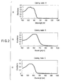
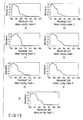
- Reference numeral (a) of FIG. 2 shows a change of absorbance of the emitted laser light relevant to a wavelength in the above coloring matter A.
- Reference numeral (b) of FIG. 2 shows a change of absorbance of the emitted laser light relevant to a wavelength in the above coloring matter B.
- Reference numeral (c) of FIG. 2 shows a change of absorbance of the emitted laser light relevant to a wavelength in the above coloring matter C.
- reference numeral (a) of FIG. 3 shows a change of absorbance of the laser light relevant to a wavelength in the above coloring matter D.
- reference numeral (b) of FIG. 3 shows a change of absorbance of the emitted laser light relevant to a wavelength in the anion portion of the above coloring matter D.
- a write-once optical disk described in the present embodiment is configured so as to have a so-called L-to-H feature in which organic coloring matters having the above-described features are included in a recording film and the light reflectivity obtained after emission of the laser light is higher than that obtained before emission of the laser light.
- an extreme absorption wavelength of the recording film including the organic coloring matter is situated on a wavelength side which is longer than the wavelength of a laser light for recording.
- a short wavelength light beam such as ultraviolet ray
- the light reflectivity is low at the time of information recording, and thus, no cross light due to reflection scattering occurs. Therefore, even in a state in which information has been recorded in the adjacent tracks, the lowering of the reproduction signal S/N ratio or the bit error rate can be restricted. Further, the contrast and resolution of the recording mark can be maintained with a high quality relevant to heat generation, and a recording sensitivity design can be easily made.
- the groove width is equal to the land width or if the groove width is smaller than the land width, it was found that the reproduction signal S/N ratio and bit error rate of the recorded information are prone to lower. Namely, it was found that good recording and reproduction features could be obtained when the groove width is larger than the land width.
- Means for recording such address information can be achieved by wobbling the groove in a radial direction of the optical disk. That is, the recording of the address information due to wobbling can be achieved by: means for modulating a wobble frequency in association with the address information; means for modulating a wobble amplitude in association with the address information; means for modulating a wobble phase in association with the address information; and means for modulating a polarity inversion interval of a wobble in association with the address information.
- means for utilizing a change of a land height as well as the wobble group, namely, means for embedding a pre-pit in the land can also be used.
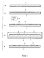
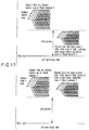
- a disk stamper for a high density R disk is prepared in accordance with the following procedures. That is, as shown in reference numeral (a) of FIG. 4, a semiconductor manufacturing silicon wafer 11 formed in a disk shape of a diameter of 200 nm and thickness of 0.725 mm is prepared.
- the silicon wafer 11 is impregnated for 5 minutes in a mixture solution of a heated condensed sulfuric acid and a hydroperoxide water (liquid temperature of 100°C). Next, the silicon wafer 11 is rinsed by impregnating it in ultra pure water, and is washed in an ultrasonic wave manner. Then, the wafer is impregnated in a 70°C ultra pure water tank, and is dried by gradually pulling it up.
- an electron beam resist film 12 is formed on a surface of the silicon wafer 11.
- the electron beam resist film 12 is formed by spin coating on the surface of the silicon wafer 11 a resist solution obtained by mixing and stirring an electron beam resist (ZEP520A7 available from Nihon Zeon Co., Ltd.) relevant to 100% by weight of an anizole solvent (ZEP-A available from Nihon Zeon Co., Ltd.).
- a groove pattern recording condition is such that an electron beam acceleration voltage is 50 kV, a beam current is 120 mA, a beam diameter is 110 nm, and a recording beam velocity is 1.1 m/sec.
- a recording region of the groove 13 is such that a radius of the silicon wafer 11 is in the range of 23 mm to 59 mm.
- the silicon wafer 11 obtained after the groove 13 has been recorded is taken out from the vacuum vessel of the electron beam cutting machine. As shown in reference numeral (d) of FIG. 4, the taken-out wafer 11 is impregnated in an organic developing liquid 16 contained in an impregnation vessel 15, and dip development is carried out, thereby forming a resist pattern of the groove 13.
- Ni electro-forming is carried out on the Ni thin film 17 to form an Ni electro-formed metal layer 18 having thickness of 247 microns.
- the Ni electro-formed metal layer 18 has been released and spin washed, the residual resist on the surface is released by oxygen RIE.
- a protection film is coated on the Ni electro-formed metal layer 18, the back face side is polished, an internal diameter and an external diameter are processed, and a disk stamper 19 is produced.
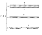
- a write-once disk is produced by using the disk stamper 19. That is, as shown in reference numeral (a) of FIG. 6, by using the disk stamper 19, as shown in reference numeral (b) of FIG. 6, a transparent disk substrate 20 made of polycarbonate having thickness of 0.6 mm is duplicated by carrying out ejection molding with an ejection molding device SD40 available from Sumitomo Heavy Industry Co., Ltd. A groove 21, of course, is formed on the disk substrate 20.
- a laser light for recording and reproduction by an optical head 29 is made incident from a face opposite to a face coated with the recording film 24 of the disk substrate 20.
- this organic coloring matter solution 23 there is used a solution having a solution concentration of 1.2% obtained by dissolving organic coloring matter powders of 1.2g % by weight in a 100 ml TFP.
- a solution condition for a solvent is such that the coloring matter powers are put in the solvent, and the resultant solution is subjected to ultrasonic waves for 30 minutes.
- Mixted color matter I is produced by adding 10% of coloring matter B to coloring matter D, namely, by mixing coloring matter B with coloring matter D at a ratio of 0.10g to 1g.
- a write-once disk 28 is produced in accordance with the above-described method, and recording and reproduction are carried out on these groove tracks Gt, thereby conducting an evaluation test.
- an evaluation device an optical disk evaluation device available from Pulse Tech Co., Ltd. is used.
- a testing condition is such that: an object lens aperture NA of the optical head 29 is 0.65; a wavelength of a laser light for recording and reproduction is 405 nm; and a linear velocity during recording and reproduction is 6.61 m/sec.
- a recording signal is obtained as random data modulated in the range of 8 to 12. That is, as shown FIG. 11, the recording signal is obtained as a waveform recorded by constant recording power and two types of bias powers 1 and 2.
- the evaluation features include a measurement result of each of three types, i.e., a carrier to noise ratio CNR of a reproduction signal; an SN ratio PRSNR (partial response signal to noise ratio) during partial response; and a simulated bit error rate (SbFR) .
- a definition and measuring techniques of PRSNR are described in a book available from DVD Format Logo Licensing Co., Ltd. for example, Annex H of Version 0.9, PART 1 Physical Specifications, DVD Specifications for High Density Read-Only Disk. It is preferable that PRSNR is 15 or more.
- a definition and measuring techniques of SbER are described in a book available from DVD Format Logo Licensing Co., Ltd.
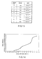
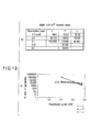
- FIG. 13 shows a measurement result of each of the write-once optical disks 28 using coloring matters D, F, G, H, I, J, K, and L. It is found that the measurement result of each of PRSNR and SbER is not good in the write-once optical disk 28 using coloring matter G. The measurement result of each of the write-once optical disks 28 using coloring matters F, H, I, J, K, and L are good as compared with those of the write-once optical disk 28 using coloring matter D.
- a disk stamper 19 is produced by changing the groove width in the range of "0.7 to 1.8" while the land width Lw is "1".
- the write-once optical disk 28 using coloring matter J is produced, and recording and reproduction are carried out for the groove track Gt, thereby conducting an evaluation test.
- the evaluation features include a measurement result of each of three types, i.e., light reflectivity, SbER, and PRSNR.
- a definition and measuring techniques of light reflectivity are described in a book available from DVD Format Logo Licensing Co., Ltd. for example, Annex D of Version 0.9, PART 1 Physical Specifications, DVD Specifications for High Density Read-Only Disk.
- the reflectivity is preferably 14% or more, more preferably in the range of 16% to 32%, and still more preferably 28% or less.
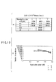
- FIG. 14 shows a measurement result of the light reflectivity with respect to the groove width Gw.
- FIG. 15 shows a measurement result of SbER with respect to the groove width Gw.
- FIG. 16 shows a measurement result of PRSNR with respect to the groove width Gw.
- the solid line indicates a state in which information has been recorded in the adjacent tracks
- the dotted line indicates a state in which no information is recorded in the adjacent tracks.
- the light reflectivity is preferably substantially 16.0% or more. More preferably, the light reflectivity is in the range of 18.0% to 32.0%, and still more preferably, the light reflectivity is 28.0% or less. It is preferable that SbER is 5.0 ⁇ 10 -5 or less. It is preferable that PRSNR is 15 or more.
- FIGS. 14 to 16 each show features in the case where the groove width Gw has been changed with respect to the write-once optical disk 28 using coloring matter J.
- a measurement result of each of the light reflectivity, SbER, and PRSNR in the case where the groove width Gw has been changed is obtained to be good when the groove width Gw is in the range of "1.05 to 1.5" while the land width Lw is "1".
- a track pitch of the recording data region groove is selected as 400 nm or in the range of 320 nm to 300 nm, it is preferable that a track pitch of the pit array in this management information region is formed to be wider than that of the recording data region groove, and a data bit pitch of the pit is formed to be greater than that of the recording data region, because reproduction can be easily carried out, and the management information can be easily discriminated.
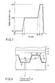
- Reference numeral (a) of FIG. 17 shows a reproduction signal waveform in a system lead-in region of a High-to-Low recording disk and a reproduction signal waveform obtained after data has been recorded in a recording data region (region in which a groove is formed).
- Reference numeral (b) of FIG. 17 shows a reproduction signal waveform in a system lead-in region of a Low-to-High recording disk and a reproduction signal waveform obtained after data has been recorded in a recording data region (region in which a groove is formed).
- the write-once optical disk produced by using coloring matter L exhibits a good result in the vicinity of reproduction power of 0.4 mW.
- the thickness of the recording film is set to 79 nm on the groove, and is set to 36 nm on the land.
- the above thickness is set to 79 nm on the groove, and set to 56 nm on the land.
- the thickness of a recording film in a conventional CD-R or DVD-R becomes very small as shown in reference numeral (c) of FIG. 20.
- the recording film thickness on the groove is set in the range of 50 nm to 120 nm, and set in the range of 20 nm to 70 nm, thereby making it possible to remarkably improve RPSNR, SbER, wobble cross talk, or radial deviation.
- a good result can be obtained by setting a ratio of the recording film thickness on the groove to the recording film thickness on the land to 1.3 to 3. Further, it is effective to set the groove width and the groove depth in the range of 220 nm to 270 nm and in the range of 50 nm to 80 nm, respectively.
- a recording mark without any irregularity change is formed on the recording film of the write-once optical disk.
- a recording system formed in an irregular shape for deforming a substrate such as a punching system.
- the present invention is not limited to the above-described embodiments. At the stage of implementation, various modifications of constituent elements can occur without departing the spirit of the invention. In addition, a variety of inventions can be formed by properly combining a plurality of constituent elements disclosed in the above embodiment. For example, some of all the constituent elements disclosed in the embodiments may be eliminated. Further, the constituent elements according to the different embodiments may be properly combined with each other.
Landscapes
- Chemical & Material Sciences (AREA)
- Organic Chemistry (AREA)
- Thermal Transfer Or Thermal Recording In General (AREA)
- Optical Record Carriers And Manufacture Thereof (AREA)
Applications Claiming Priority (4)
| Application Number | Priority Date | Filing Date | Title |
|---|---|---|---|
| JP2004110384A JP2005293772A (ja) | 2004-04-02 | 2004-04-02 | 追記型情報記録媒体及びその色素材料 |
| JP2004110384 | 2004-04-02 | ||
| JP2005079627 | 2005-03-18 | ||
| JP2005079627A JP2006260716A (ja) | 2005-03-18 | 2005-03-18 | 追記型情報記録媒体及びその色素材料 |
Publications (3)
| Publication Number | Publication Date |
|---|---|
| EP1585124A2 true EP1585124A2 (de) | 2005-10-12 |
| EP1585124A3 EP1585124A3 (de) | 2006-04-19 |
| EP1585124B1 EP1585124B1 (de) | 2009-06-24 |
Family
ID=34914559
Family Applications (1)
| Application Number | Title | Priority Date | Filing Date |
|---|---|---|---|
| EP05102522A Expired - Lifetime EP1585124B1 (de) | 2004-04-02 | 2005-03-30 | Einmalig beschreibbares Aufzeichnungsmedium und Farbstoff dafür |
Country Status (5)
| Country | Link |
|---|---|
| US (1) | US7876666B2 (de) |
| EP (1) | EP1585124B1 (de) |
| CN (1) | CN1677527B (de) |
| DE (1) | DE602005015053D1 (de) |
| TW (1) | TWI320424B (de) |
Cited By (1)
| Publication number | Priority date | Publication date | Assignee | Title |
|---|---|---|---|---|
| EP2469512A3 (de) * | 2005-07-29 | 2012-08-01 | Kabushiki Kaisha Toshiba | Optischer Kopf und Informationsaufzeichnungs-/Informationswiedergabevorrichtung |
Families Citing this family (15)
| Publication number | Priority date | Publication date | Assignee | Title |
|---|---|---|---|---|
| EP1178083A4 (de) * | 1999-12-17 | 2002-05-29 | Hayashibara Biochem Lab | Cyaninfarbstoff |
| JP2005293773A (ja) * | 2004-04-02 | 2005-10-20 | Toshiba Corp | 追記型情報記録媒体 |
| JP2005288972A (ja) * | 2004-04-02 | 2005-10-20 | Toshiba Corp | 追記型情報記録媒体 |
| JP2005297406A (ja) * | 2004-04-13 | 2005-10-27 | Toshiba Corp | 媒体用記録材料 |
| JP2006236421A (ja) * | 2005-02-22 | 2006-09-07 | Toshiba Corp | 記憶媒体、再生方法及び記録方法 |
| JP4417869B2 (ja) * | 2005-03-15 | 2010-02-17 | 株式会社東芝 | 情報記憶媒体、再生方法及び記録方法 |
| JP4575211B2 (ja) * | 2005-03-31 | 2010-11-04 | 株式会社東芝 | 記憶媒体、再生方法及び記録方法 |
| JP2006289877A (ja) * | 2005-04-14 | 2006-10-26 | Toshiba Corp | 情報記憶媒体、再生方法及び記録方法 |
| JP4473768B2 (ja) * | 2005-04-14 | 2010-06-02 | 株式会社東芝 | 情報記憶媒体、再生方法及び記録方法 |
| TW200809845A (en) * | 2006-03-06 | 2008-02-16 | Ricoh Co Ltd | Optical recording medium, and method for initializing the optical recording medium |
| JP2008142895A (ja) * | 2006-12-05 | 2008-06-26 | Fujifilm Corp | モールド構造体 |
| US20080229349A1 (en) * | 2007-03-15 | 2008-09-18 | Ollmann Richard R | Recordable optical data storage disc |
| US7981494B2 (en) * | 2007-03-20 | 2011-07-19 | Taiyo Yuden Co., Ltd. | Optical informaton recording medium |
| JP2009080895A (ja) * | 2007-09-26 | 2009-04-16 | Toshiba Corp | 情報記録媒体及びこの媒体を用いたディスク装置 |
| JP4427582B2 (ja) * | 2008-01-31 | 2010-03-10 | 株式会社東芝 | 追記型情報記録媒体及びディスク装置 |
Family Cites Families (40)
| Publication number | Priority date | Publication date | Assignee | Title |
|---|---|---|---|---|
| GB8817897D0 (en) | 1988-07-27 | 1988-09-01 | Minnesota Mining & Mfg | Polymethine dyes suitable for optical recording media |
| US5514440A (en) * | 1991-09-27 | 1996-05-07 | Fuji Xerox Co., Ltd. | Optical recording medium and optical recording method using the same |
| US5776656A (en) * | 1995-07-28 | 1998-07-07 | Tdk Corporation | Optical recording medium |
| TW314621B (de) | 1995-12-20 | 1997-09-01 | Toshiba Co Ltd | |
| US6071672A (en) * | 1997-02-10 | 2000-06-06 | Tdk Corporation | Photo-stabilized cyanine dyes and optical recording media |
| JP3685922B2 (ja) * | 1997-11-05 | 2005-08-24 | Tdk株式会社 | 光記録媒体およびその記録方法 |
| CA2337480A1 (en) | 1998-08-11 | 2000-02-24 | Beat Schmidhalter | Metallocenyl-phthalocyanines |
| JP2000311384A (ja) | 1999-04-26 | 2000-11-07 | Fuji Photo Film Co Ltd | 光情報記録媒体 |
| EP1178083A4 (de) | 1999-12-17 | 2002-05-29 | Hayashibara Biochem Lab | Cyaninfarbstoff |
| TW572969B (en) | 2000-02-10 | 2004-01-21 | Hayashibara Biochem Lab | Trimethine cyanine dye, light absorbent, light-resistant improver and optical recording medium containing same, and process for producing same |
| TW556155B (en) | 2000-04-03 | 2003-10-01 | Sony Corp | Optical record medium |
| JP2001312838A (ja) | 2000-04-27 | 2001-11-09 | Teijin Chem Ltd | 光ディスク基板およびそれを用いた追記型光情報記録媒体 |
| JP2001344812A (ja) * | 2000-06-02 | 2001-12-14 | Fuji Photo Film Co Ltd | 光情報記録媒体 |
| CN1201309C (zh) * | 2000-06-16 | 2005-05-11 | 三菱化学株式会社 | 光信息记录介质 |
| JP2002206061A (ja) * | 2000-07-05 | 2002-07-26 | Hayashibara Biochem Lab Inc | スチリル色素 |
| US6741547B2 (en) * | 2000-08-10 | 2004-05-25 | Ricoh Company, Ltd. | Optical recording medium having short wobble period length |
| JP2002074740A (ja) | 2000-08-25 | 2002-03-15 | Hayashibara Biochem Lab Inc | 光記録媒体 |
| JP2002092962A (ja) * | 2000-09-20 | 2002-03-29 | Nec Corp | 光学情報記録媒体 |
| WO2002043060A1 (fr) | 2000-11-27 | 2002-05-30 | Tdk Corporation | Moyen d'enregistrement optique |
| JP3989846B2 (ja) | 2001-03-21 | 2007-10-10 | チバ スペシャルティ ケミカルズ ホールディング インコーポレーテッド | 高い記憶密度を有する光学記録材料 |
| JP2002324320A (ja) | 2001-04-24 | 2002-11-08 | Ricoh Co Ltd | 光記録媒体及びその記録方法 |
| TWI292910B (de) | 2001-06-11 | 2008-01-21 | Sony Corp | |
| JP2003085778A (ja) * | 2001-06-29 | 2003-03-20 | Sony Corp | 光学記録再生媒体、光学記録再生媒体製造用マザースタンパ及び光学記録再生装置 |
| JP2003020416A (ja) | 2001-07-06 | 2003-01-24 | Fuji Photo Film Co Ltd | テトラシアノキノジメタン化合物を対アニオンとした特定構造のシアニン色素化合物及び該シアニン色素化合物を含む光情報記録媒体 |
| DE10140860A1 (de) | 2001-08-21 | 2003-03-13 | Bayer Ag | Verfahren zur Herstellung von Styrylfarbstoffen |
| JP3833961B2 (ja) | 2001-12-28 | 2006-10-18 | 株式会社リコー | 追記型光記録媒体 |
| JP2003308630A (ja) | 2002-02-15 | 2003-10-31 | Sony Corp | 書き換え可能型光情報記録媒体及び記録再生方法、記録再生装置 |
| CN100401400C (zh) | 2002-02-15 | 2008-07-09 | 索尼株式会社 | 可再书写光学信息记录介质、记录/再现方法及记录/再现设备 |
| JP3880871B2 (ja) * | 2002-02-26 | 2007-02-14 | 株式会社リコー | 光記録媒体及びそれを用いた光記録方法 |
| JP3844704B2 (ja) | 2002-03-12 | 2006-11-15 | 株式会社リコー | 多値記録可能な追記型光記録媒体及び多値記録方法 |
| JP2003303442A (ja) | 2002-04-08 | 2003-10-24 | Sony Corp | 光学記録媒体 |
| JP4065719B2 (ja) | 2002-05-10 | 2008-03-26 | 株式会社リコー | 追記型光記録媒体及びその記録再生方法 |
| JP3897695B2 (ja) | 2002-12-27 | 2007-03-28 | 株式会社リコー | 短波長対応のロー・ツー・ハイ記録極性を有する追記型光記録媒体 |
| JP4117881B2 (ja) | 2003-02-21 | 2008-07-16 | 株式会社リコー | 追記型光記録媒体 |
| JP2004296052A (ja) | 2003-03-25 | 2004-10-21 | Ricoh Co Ltd | 追記型光記録媒体および記録再生方法 |
| JP2005196817A (ja) * | 2003-12-26 | 2005-07-21 | Toshiba Corp | 情報記録媒体 |
| JP2005288972A (ja) * | 2004-04-02 | 2005-10-20 | Toshiba Corp | 追記型情報記録媒体 |
| JP2005293773A (ja) * | 2004-04-02 | 2005-10-20 | Toshiba Corp | 追記型情報記録媒体 |
| JP2005293772A (ja) | 2004-04-02 | 2005-10-20 | Toshiba Corp | 追記型情報記録媒体及びその色素材料 |
| JP4417869B2 (ja) * | 2005-03-15 | 2010-02-17 | 株式会社東芝 | 情報記憶媒体、再生方法及び記録方法 |
-
2005
- 2005-03-25 US US11/089,037 patent/US7876666B2/en not_active Expired - Fee Related
- 2005-03-28 TW TW094109640A patent/TWI320424B/zh not_active IP Right Cessation
- 2005-03-30 EP EP05102522A patent/EP1585124B1/de not_active Expired - Lifetime
- 2005-03-30 DE DE602005015053T patent/DE602005015053D1/de not_active Expired - Lifetime
- 2005-04-01 CN CN2005100628651A patent/CN1677527B/zh not_active Expired - Fee Related
Cited By (3)
| Publication number | Priority date | Publication date | Assignee | Title |
|---|---|---|---|---|
| EP2469512A3 (de) * | 2005-07-29 | 2012-08-01 | Kabushiki Kaisha Toshiba | Optischer Kopf und Informationsaufzeichnungs-/Informationswiedergabevorrichtung |
| EP2469536A3 (de) * | 2005-07-29 | 2012-08-01 | Kabushiki Kaisha Toshiba | Optischer Kopf und Informationsaufzeichnungs-/Informationswiedergabevorrichtung |
| US8717858B2 (en) | 2005-07-29 | 2014-05-06 | Kabushiki Kaisha Toshiba | Write-once type information storage medium (disk structure of recording type information storage medium having structure in which recording layer formed on transparent susbstrate is defined as inside), and information reproducing method or information recording method as well as storage medium manufacturing |
Also Published As
| Publication number | Publication date |
|---|---|
| TW200605064A (en) | 2006-02-01 |
| CN1677527A (zh) | 2005-10-05 |
| CN1677527B (zh) | 2010-12-29 |
| US20050219997A1 (en) | 2005-10-06 |
| US7876666B2 (en) | 2011-01-25 |
| DE602005015053D1 (de) | 2009-08-06 |
| TWI320424B (en) | 2010-02-11 |
| EP1585124A3 (de) | 2006-04-19 |
| EP1585124B1 (de) | 2009-06-24 |
Similar Documents
| Publication | Publication Date | Title |
|---|---|---|
| EP1587092B1 (de) | Einmalig beschreibbares Aufzeichnungsmedium und Farbstoff dafür | |
| EP1585124B1 (de) | Einmalig beschreibbares Aufzeichnungsmedium und Farbstoff dafür | |
| US20050219995A1 (en) | Write-once information recording medium | |
| US20050219996A1 (en) | Write-once information recording medium | |
| KR100698859B1 (ko) | 매체용 기록 재료 | |
| TW200814040A (en) | Recordable information recording medium and disk apparatus | |
| US8422353B2 (en) | Optical recording medium for writing data using multiple pulses | |
| CN100378839C (zh) | 信息存储介质 | |
| CN101097744A (zh) | 一次写入型信息记录介质及盘设备 | |
| JP2005293772A (ja) | 追記型情報記録媒体及びその色素材料 | |
| JP2009009697A (ja) | 追記型情報記録媒体を用いた情報記録方法 | |
| JP2006260716A (ja) | 追記型情報記録媒体及びその色素材料 | |
| JP2009009698A (ja) | 追記型情報記録媒体を用いた情報記録方法 | |
| US20070037094A1 (en) | Information storage medium, and reproducing method and recording method therefor |
Legal Events
| Date | Code | Title | Description |
|---|---|---|---|
| PUAI | Public reference made under article 153(3) epc to a published international application that has entered the european phase |
Free format text: ORIGINAL CODE: 0009012 |
|
| 17P | Request for examination filed |
Effective date: 20050331 |
|
| AK | Designated contracting states |
Kind code of ref document: A2 Designated state(s): AT BE BG CH CY CZ DE DK EE ES FI FR GB GR HU IE IS IT LI LT LU MC NL PL PT RO SE SI SK TR |
|
| AX | Request for extension of the european patent |
Extension state: AL BA HR LV MK YU |
|
| PUAL | Search report despatched |
Free format text: ORIGINAL CODE: 0009013 |
|
| AK | Designated contracting states |
Kind code of ref document: A3 Designated state(s): AT BE BG CH CY CZ DE DK EE ES FI FR GB GR HU IE IS IT LI LT LU MC NL PL PT RO SE SI SK TR |
|
| AX | Request for extension of the european patent |
Extension state: AL BA HR LV MK YU |
|
| 17Q | First examination report despatched |
Effective date: 20060823 |
|
| AKX | Designation fees paid |
Designated state(s): DE FR GB |
|
| GRAP | Despatch of communication of intention to grant a patent |
Free format text: ORIGINAL CODE: EPIDOSNIGR1 |
|
| GRAS | Grant fee paid |
Free format text: ORIGINAL CODE: EPIDOSNIGR3 |
|
| GRAA | (expected) grant |
Free format text: ORIGINAL CODE: 0009210 |
|
| AK | Designated contracting states |
Kind code of ref document: B1 Designated state(s): DE FR GB |
|
| REG | Reference to a national code |
Ref country code: GB Ref legal event code: FG4D |
|
| REF | Corresponds to: |
Ref document number: 602005015053 Country of ref document: DE Date of ref document: 20090806 Kind code of ref document: P |
|
| PLBE | No opposition filed within time limit |
Free format text: ORIGINAL CODE: 0009261 |
|
| STAA | Information on the status of an ep patent application or granted ep patent |
Free format text: STATUS: NO OPPOSITION FILED WITHIN TIME LIMIT |
|
| 26N | No opposition filed |
Effective date: 20100325 |
|
| PGFP | Annual fee paid to national office [announced via postgrant information from national office to epo] |
Ref country code: FR Payment date: 20140311 Year of fee payment: 10 |
|
| PGFP | Annual fee paid to national office [announced via postgrant information from national office to epo] |
Ref country code: GB Payment date: 20140326 Year of fee payment: 10 |
|
| PGFP | Annual fee paid to national office [announced via postgrant information from national office to epo] |
Ref country code: DE Payment date: 20140417 Year of fee payment: 10 |
|
| REG | Reference to a national code |
Ref country code: DE Ref legal event code: R119 Ref document number: 602005015053 Country of ref document: DE |
|
| GBPC | Gb: european patent ceased through non-payment of renewal fee |
Effective date: 20150330 |
|
| REG | Reference to a national code |
Ref country code: FR Ref legal event code: ST Effective date: 20151130 |
|
| PG25 | Lapsed in a contracting state [announced via postgrant information from national office to epo] |
Ref country code: GB Free format text: LAPSE BECAUSE OF NON-PAYMENT OF DUE FEES Effective date: 20150330 Ref country code: DE Free format text: LAPSE BECAUSE OF NON-PAYMENT OF DUE FEES Effective date: 20151001 |
|
| PG25 | Lapsed in a contracting state [announced via postgrant information from national office to epo] |
Ref country code: FR Free format text: LAPSE BECAUSE OF NON-PAYMENT OF DUE FEES Effective date: 20150331 |