EP1584807B1 - Control method for an exhaust gas purification system and an exhaust gas purification system - Google Patents
Control method for an exhaust gas purification system and an exhaust gas purification system Download PDFInfo
- Publication number
- EP1584807B1 EP1584807B1 EP05102139.2A EP05102139A EP1584807B1 EP 1584807 B1 EP1584807 B1 EP 1584807B1 EP 05102139 A EP05102139 A EP 05102139A EP 1584807 B1 EP1584807 B1 EP 1584807B1
- Authority
- EP
- European Patent Office
- Prior art keywords
- exhaust gas
- regeneration
- control
- water temperature
- gas temperature
- Prior art date
- Legal status (The legal status is an assumption and is not a legal conclusion. Google has not performed a legal analysis and makes no representation as to the accuracy of the status listed.)
- Ceased
Links
Images


Classifications
-
- F—MECHANICAL ENGINEERING; LIGHTING; HEATING; WEAPONS; BLASTING
- F02—COMBUSTION ENGINES; HOT-GAS OR COMBUSTION-PRODUCT ENGINE PLANTS
- F02D—CONTROLLING COMBUSTION ENGINES
- F02D41/00—Electrical control of supply of combustible mixture or its constituents
- F02D41/02—Circuit arrangements for generating control signals
- F02D41/021—Introducing corrections for particular conditions exterior to the engine
- F02D41/0235—Introducing corrections for particular conditions exterior to the engine in relation with the state of the exhaust gas treating apparatus
- F02D41/027—Introducing corrections for particular conditions exterior to the engine in relation with the state of the exhaust gas treating apparatus to purge or regenerate the exhaust gas treating apparatus
- F02D41/029—Introducing corrections for particular conditions exterior to the engine in relation with the state of the exhaust gas treating apparatus to purge or regenerate the exhaust gas treating apparatus the exhaust gas treating apparatus being a particulate filter
-
- F—MECHANICAL ENGINEERING; LIGHTING; HEATING; WEAPONS; BLASTING
- F01—MACHINES OR ENGINES IN GENERAL; ENGINE PLANTS IN GENERAL; STEAM ENGINES
- F01N—GAS-FLOW SILENCERS OR EXHAUST APPARATUS FOR MACHINES OR ENGINES IN GENERAL; GAS-FLOW SILENCERS OR EXHAUST APPARATUS FOR INTERNAL-COMBUSTION ENGINES
- F01N3/00—Exhaust or silencing apparatus having means for purifying, rendering innocuous, or otherwise treating exhaust
- F01N3/02—Exhaust or silencing apparatus having means for purifying, rendering innocuous, or otherwise treating exhaust for cooling, or for removing solid constituents of, exhaust
- F01N3/021—Exhaust or silencing apparatus having means for purifying, rendering innocuous, or otherwise treating exhaust for cooling, or for removing solid constituents of, exhaust by means of filters
- F01N3/023—Exhaust or silencing apparatus having means for purifying, rendering innocuous, or otherwise treating exhaust for cooling, or for removing solid constituents of, exhaust by means of filters using means for regenerating the filters, e.g. by burning trapped particles
- F01N3/0231—Exhaust or silencing apparatus having means for purifying, rendering innocuous, or otherwise treating exhaust for cooling, or for removing solid constituents of, exhaust by means of filters using means for regenerating the filters, e.g. by burning trapped particles using special exhaust apparatus upstream of the filter for producing nitrogen dioxide, e.g. for continuous filter regeneration systems [CRT]
-
- F—MECHANICAL ENGINEERING; LIGHTING; HEATING; WEAPONS; BLASTING
- F01—MACHINES OR ENGINES IN GENERAL; ENGINE PLANTS IN GENERAL; STEAM ENGINES
- F01N—GAS-FLOW SILENCERS OR EXHAUST APPARATUS FOR MACHINES OR ENGINES IN GENERAL; GAS-FLOW SILENCERS OR EXHAUST APPARATUS FOR INTERNAL-COMBUSTION ENGINES
- F01N3/00—Exhaust or silencing apparatus having means for purifying, rendering innocuous, or otherwise treating exhaust
- F01N3/02—Exhaust or silencing apparatus having means for purifying, rendering innocuous, or otherwise treating exhaust for cooling, or for removing solid constituents of, exhaust
- F01N3/021—Exhaust or silencing apparatus having means for purifying, rendering innocuous, or otherwise treating exhaust for cooling, or for removing solid constituents of, exhaust by means of filters
- F01N3/023—Exhaust or silencing apparatus having means for purifying, rendering innocuous, or otherwise treating exhaust for cooling, or for removing solid constituents of, exhaust by means of filters using means for regenerating the filters, e.g. by burning trapped particles
- F01N3/0235—Exhaust or silencing apparatus having means for purifying, rendering innocuous, or otherwise treating exhaust for cooling, or for removing solid constituents of, exhaust by means of filters using means for regenerating the filters, e.g. by burning trapped particles using exhaust gas throttling means
-
- F—MECHANICAL ENGINEERING; LIGHTING; HEATING; WEAPONS; BLASTING
- F02—COMBUSTION ENGINES; HOT-GAS OR COMBUSTION-PRODUCT ENGINE PLANTS
- F02D—CONTROLLING COMBUSTION ENGINES
- F02D41/00—Electrical control of supply of combustible mixture or its constituents
- F02D41/02—Circuit arrangements for generating control signals
- F02D41/021—Introducing corrections for particular conditions exterior to the engine
- F02D41/0235—Introducing corrections for particular conditions exterior to the engine in relation with the state of the exhaust gas treating apparatus
- F02D41/024—Introducing corrections for particular conditions exterior to the engine in relation with the state of the exhaust gas treating apparatus to increase temperature of the exhaust gas treating apparatus
- F02D41/0245—Introducing corrections for particular conditions exterior to the engine in relation with the state of the exhaust gas treating apparatus to increase temperature of the exhaust gas treating apparatus by increasing temperature of the exhaust gas leaving the engine
-
- F—MECHANICAL ENGINEERING; LIGHTING; HEATING; WEAPONS; BLASTING
- F02—COMBUSTION ENGINES; HOT-GAS OR COMBUSTION-PRODUCT ENGINE PLANTS
- F02D—CONTROLLING COMBUSTION ENGINES
- F02D41/00—Electrical control of supply of combustible mixture or its constituents
- F02D41/22—Safety or indicating devices for abnormal conditions
- F02D2041/228—Warning displays
-
- F—MECHANICAL ENGINEERING; LIGHTING; HEATING; WEAPONS; BLASTING
- F02—COMBUSTION ENGINES; HOT-GAS OR COMBUSTION-PRODUCT ENGINE PLANTS
- F02D—CONTROLLING COMBUSTION ENGINES
- F02D2200/00—Input parameters for engine control
- F02D2200/02—Input parameters for engine control the parameters being related to the engine
- F02D2200/08—Exhaust gas treatment apparatus parameters
- F02D2200/0812—Particle filter loading
-
- F—MECHANICAL ENGINEERING; LIGHTING; HEATING; WEAPONS; BLASTING
- F02—COMBUSTION ENGINES; HOT-GAS OR COMBUSTION-PRODUCT ENGINE PLANTS
- F02D—CONTROLLING COMBUSTION ENGINES
- F02D2250/00—Engine control related to specific problems or objectives
- F02D2250/11—Oil dilution, i.e. prevention thereof or special controls according thereto
-
- F—MECHANICAL ENGINEERING; LIGHTING; HEATING; WEAPONS; BLASTING
- F02—COMBUSTION ENGINES; HOT-GAS OR COMBUSTION-PRODUCT ENGINE PLANTS
- F02D—CONTROLLING COMBUSTION ENGINES
- F02D41/00—Electrical control of supply of combustible mixture or its constituents
- F02D41/02—Circuit arrangements for generating control signals
- F02D41/04—Introducing corrections for particular operating conditions
- F02D41/047—Taking into account fuel evaporation or wall wetting
-
- F—MECHANICAL ENGINEERING; LIGHTING; HEATING; WEAPONS; BLASTING
- F02—COMBUSTION ENGINES; HOT-GAS OR COMBUSTION-PRODUCT ENGINE PLANTS
- F02D—CONTROLLING COMBUSTION ENGINES
- F02D41/00—Electrical control of supply of combustible mixture or its constituents
- F02D41/02—Circuit arrangements for generating control signals
- F02D41/14—Introducing closed-loop corrections
- F02D41/1438—Introducing closed-loop corrections using means for determining characteristics of the combustion gases; Sensors therefor
- F02D41/1444—Introducing closed-loop corrections using means for determining characteristics of the combustion gases; Sensors therefor characterised by the characteristics of the combustion gases
- F02D41/1446—Introducing closed-loop corrections using means for determining characteristics of the combustion gases; Sensors therefor characterised by the characteristics of the combustion gases the characteristics being exhaust temperatures
-
- Y—GENERAL TAGGING OF NEW TECHNOLOGICAL DEVELOPMENTS; GENERAL TAGGING OF CROSS-SECTIONAL TECHNOLOGIES SPANNING OVER SEVERAL SECTIONS OF THE IPC; TECHNICAL SUBJECTS COVERED BY FORMER USPC CROSS-REFERENCE ART COLLECTIONS [XRACs] AND DIGESTS
- Y02—TECHNOLOGIES OR APPLICATIONS FOR MITIGATION OR ADAPTATION AGAINST CLIMATE CHANGE
- Y02T—CLIMATE CHANGE MITIGATION TECHNOLOGIES RELATED TO TRANSPORTATION
- Y02T10/00—Road transport of goods or passengers
- Y02T10/10—Internal combustion engine [ICE] based vehicles
- Y02T10/12—Improving ICE efficiencies
Definitions
- the present invention relates to an exhaust gas purification system that purifies particulate matters (PM) from the exhaust gas discharged by diesel and other internal combustion engines using a continuous regeneration-type diesel particulate filter (DPF) device and also to a control method thereof.
- PM particulate matters
- PM particulate matters
- the exhaust gas temperature is raised by executing the exhaust raising control of the multi injection and the exhaust throttle etc.
- the fuel in the exhaust gas is burned through oxidation catalyst.
- the filter is regenerated through burning and removing collected PM after raising the exhaust gas temperature higher than the temperature the PM in the filter can be burned.
- Japanese Patent Application Kokai Publication No. 2004-19496 discloses an exhaust-gas purification system of an internal combustion engine, in which it is possible to restrain deterioration of fuel efficiency by relatively easy controls and to perform the regeneration safely and efficiently.
- the DPF is heated and regenerated only when the operation condition is at high temperature raising efficiency in the case where the collected PM quantity is not less than the first threshold value but less than the second threshold value, and regeneration is performed in the case where the collected PM quantity becomes the second threshold value or more, even if the operation condition is not at a high temperature raising efficiency.
- a method which not only automatically performs forced regeneration during traveling but also performs a forced regeneration in a vehicle stationary idling condition when a clogged filter is notified to a driver by a DPF lamp and the driver stops the vehicle and presses a manual regeneration switch.
- a method is also considered which accelerates self-regeneration by performing the exhaust gas temperature raising control and at the same time, closes an exhaust throttle butterfly.
- a driver receiving a warning stops the vehicle and presses a manual regeneration switch to perform a forced regeneration. Then, the idle rotating speed is increased at the time of a vehicle stationary idling, a multi injection is performed by closing an exhaust brake, and a post injection is performed when an exhaust gas temperature rises up to an oxidation catalyst activation temperature or higher.
- the exhaust gas temperature rises and the engine cooling water temperature also rises. Therefore, the water temperature meter in the driver seat also rises due to the cooling water temperature rise, and thereby, upon watching the water temperature meter, the driver may take it that a vehicle trouble such as an engine trouble occurs.
- Document JP-2004346755 discloses a control device for an engine.
- an oxidation catalyst and a filter are disposed within an exhaust passage and the oxidation catalyst is heated by increasing an exhaust gas temperature only, if the engine water temperature is not increased over a predetermined value.
- Document EP 1291514 discloses an exhaust emission control device or an engine.
- Said device comprises a particulate filter for re-burning deposited soot, a temperature sensor for detecting the exhaust gas temperature on the upper stream side of the particulate filter, and a control unit for determining whether or not a condition for the interruption of regeneration is fulfilled.
- a control method for an exhaust gas purification system in an internal combustion engine mounted on a vehicle provided with a continuous regeneration type diesel particulate filter device in the exhaust passage thereof; including diesel particulate filter control steps comprising: a regeneration timing judgment step for judging a regeneration timing of a filter of the continuous regeneration type diesel particulate filter device, an exhaust gas temperature raising step for raising exhaust gas temperature, a cooling water temperature detection step for detecting an engine cooling water temperature, in which the exhaust gas temperature is raised to regenerate the filter by performing a forced regeneration control at the exhaust gas temperature raising step when the timing for regeneration is judged at the regeneration timing judgment step and the exhaust gas temperature is lower than a predetermined judgment exhaust gas temperature, characterized in that the exhaust gas temperature raising is interrupted when the engine cooling water temperature exceeds a predetermined judgment water temperature during the forced regeneration control of the filter at the exhaust gas temperature raising step.
- the above described control method for the exhaust gas purification system is characterized in that the DPF control means comprises: a manual regeneration mode for performing the forced regeneration control of the filter when a driver presses a manual regeneration switch upon warning to perform a regeneration control under a vehicle stationary idling condition, and an automatic travelling regeneration mode for automatically performing the forced regeneration control of the filter when a vehicle travels, and a first predetermined judgment water temperature in the manual regeneration mode is set to a temperature higher than a second predetermined judgment water temperature in the automatic travelling regeneration mode, in the predetermined judgment water temperature for interrupting the actuation of the exhaust gas temperature raising means.
- the exhaust gas temperature raising means includes at least either a multi injection or an exhaust throttle control.
- control method for the exhaust gas purification system is characterized in that an unburned fuel addition means for post injection control in addition to the actuation of the exhaust gas temperature raising means is actuated in the forced regeneration control of the filter, and when an engine cooling water temperature detected by the cooling water temperature detection means exceeds the predetermined judgment water temperature, the actuation of the exhaust gas temperature raising means as well as the unburned fuel addition means is interrupted.
- an exhaust gas purification system in an internal combustion engine mounted on a vehicle provided with a diesel particulate filter device in the exhaust gas passage thereof; having a diesel particulate filter control means including: a regeneration timing judgment means for judging a regeneration timing of a filter of the continuous regeneration type diesel particulate filter device, an exhaust gas temperature raising means for raising exhaust gas temperature, a cooling water temperature detection means for detecting an engine cooling water temperature, in which said diesel particulate filter control means raises an exhaust gas temperature by the exhaust gas temperature raising means to regenerate the filter by performing a forced regeneration control, when the timing for regeneration is judged by the regeneration timing judgment means and that an exhaust gas temperature is lower than a predetermined judgment exhaust gas temperature, wherein said diesel particulate filter control means is comprised to constitute that the actuation of the exhaust gas temperature raising means is interrupted, when the engine cooling water temperature detected by the cooling water temperature detection means exceeds a predetermined judgment water temperature during the forced regeneration control of the filter using the exhaust gas temperature raising means.
- said DPF control means comprises a manual regeneration mode for performing the forced regeneration control of the filter when a driver presses a manual regeneration switch upon warning to perform a regeneration control under a vehicle stationary idling condition, and an automatic traveling regeneration mode for automatically performing the forced regeneration control of the filter when a vehicle travels; and in the predetermined judgment water temperature for interrupting the actuation of the exhaust gas temperature raising means, a first predetermined judgment water temperature in the manual regeneration mode is set to a temperature higher than a second predetermined judgment water temperature in the automatic traveling regeneration mode.
- the DPF device is constituted of any one or a combination of; a DPF device formed of a filter without supporting catalyst, a continuous regeneration type DPF device supporting an oxidation catalyst on the filter, a continuous regeneration type DPF device in which an oxidation catalyst is installed on the upstream side of the filter, and a continuous regeneration type DPF device in which an oxidation catalyst is supported on the filter or installed on the upstream side thereof.
- a water temperature meter at the driver seat is not abnormally raised during forced regeneration of the DPF and it is possible to avoid that a driver takes an overheat for an engine trouble.
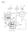
- FIG. 1 shows the configuration of an exhaust gas purification system 1 for an internal combustion engine according to an embodiment of the present invention.
- This exhaust gas purification system 1 is configured to provide a continuous regeneration DPF device 13 on an exhaust passage 12 connected to an exhaust manifold 11 of a diesel engine 10.
- This continuous regeneration DPF device 13 is configured with an oxidation catalyst 13a on the upstream side thereof and a filter with catalyst 13b on the downstream side thereof.
- the oxidation catalyst 13a is formed so as to support an oxidation catalyst of platinum (Pt) etc. on a support with a porous ceramic honeycomb structure etc.
- the filter with catalyst 13b is formed of a monolithic honeycomb type, wall flow type filter with entrances and exits to channels in a porous ceramic honeycomb alternately closed or a felt-type filter with randomly layered alumina other inorganic fibers or the like etc.
- a platinum or cerium oxide etc. catalyst is supported on this filter portion.
- a differential pressure sensor 21 is provided on the conduit tube in front of and behind the continuous regeneration DPF device 13 in order to estimate the collecting quantity of PM on the filter with catalyst 13b.
- an oxidation catalyst inlet exhaust gas temperature sensor 22 is provided upstream of the oxidation catalyst 13a and a filter inlet exhaust gas temperature sensor 23 is provided between the oxidation catalyst 13a and the filter with catalyst 13b.
- the output values from these sensors are input to an engine control unit (ECU) 30.
- the engine control unit 30 In addition to controlling the overall operation of the engine 10, the engine control unit 30 also performs regeneration control of the operation of the continuous regeneration DPF device 13.
- the fuel injection devices (i.e., injection nozzles) 14 of the engine 10 the intake throttle valve (not shown) adjusting the intake quantity of the intake manifold 15 and the EGR valve for adjusting the EGR volume etc. are also controlled thereby.
- the EGR valve is provided together with the EGR cooler on the EGR passage (not shown).
- These fuel injection devices 14 are connected to a common-rail fuel injection system (not shown) storing temporarily the fuel pressurized to high pressure by the fuel pump (not shown).
- the accelerator opening from the accelerator position sensor (APS) 31 and the engine speed from the engine speed sensor 32 etc. are input into the engine control unit 30 together with other data such as the vehicle speed and cooling water temperature, etc.
- the engine control device 30 comprises an engine control means 20C controlling operating of the engine and a diesel particulate filter (DPF) control means 30C for the exhaust gas purification system 1 etc.
- the DPF control means 30C comprises a normal operating means 31C, a PM collecting quantity detection means 32C, a travel distance detection means 33C, a regeneration timing judgment means 34C, a forced regeneration means 35C, a manual regeneration warning means 36C, a cooling water temperature detection means 37C, etc.
- the normal operating means 31C is in particular a means for performing normal operating unrelated to regeneration of the continuous regeneration DPF device 13.
- normal injection control is carried out wherein a predetermined volume of fuel is injected from the fuel injection devices 14 in accordance with an electric current time signal calculated in the engine control device 30 based on signals from the accelerator position sensor 31 and signals from the engine speed sensor 32.
- the PM collecting quantity detection means 32C is a means for detecting the PM collecting quantity accumulated in the filter with catalyst 13b of the continuous regeneration DPF device 13. In this embodiment, detection thereof is carried out based on the differential pressure before and after the continuous regeneration DPF device 13 - that is, the measurement values ⁇ Pm from the differential pressure sensor 21.
- the travel distance detection means 33C is a means for detecting the travel distance ⁇ Mc traveled by the vehicle after DPF regeneration. Whenever forced regeneration is carried out, this distance ⁇ Mc is reset at a suitable timing from the start of regeneration to the end thereof.
- the regeneration timing judgment means 34C is a means for judging a regeneration start timing of DPF based on comparison of the differential pressure detection value ⁇ Pm detected by the PM collecting quantity detection means 32C and the travel distance ⁇ Mc detected by the travel distance detection means 33C with respective predetermined judgment values.
- the forced regeneration means 35C comprises an exhaust gas temperature raising means 351C and an unburned fuel addition means 352C.
- the exhaust gas temperature raising means 351C performs multi injection (multi retarded injection) in an intra-cylinder injection of the engine 10, or performs exhaust throttle control, thereby raising the exhaust gas temperature to the active temperature of the oxidation catalyst 13a.
- the unburned fuel addition means 352C performs post injection thereafter, and adds unburned fuel to the exhaust gas.
- the filter inlet exhaust gas temperature detected by the filter inlet exhaust gas temperature sensor 23 is raised, realizing a suitable temperature and environment for PM oxidation and removal.
- the PM accumulated on the filter with catalyst 13b is forcibly burned and removed, and the filter with catalyst 13b is forcibly regenerated.
- the exhaust gas temperature raising means 351C is also possible to use the exhaust throttle control.
- the manual regeneration warning means 36C comprises a flashing lamp (or DPF lamp) 41 and a warning lamp 42, etc.
- This manual regeneration warning means 36C is a means for urging the driver through flashing of the flashing lamp 41 to manually actuate the forced regeneration means 35C, and through the lighting of the warning lamp 42, to bring the vehicle to a service center. Furthermore, upon receiving of this warning, the driver is capable of actuating the forced regeneration means 35C through a manual operation of a regeneration switch (manual regeneration switch) 43.
- the cooling water temperature detection means 37C is configured with the water temperature sensor 33 etc. and is a means for detecting engine cooling water temperature Tw.
- the DPF control means 30C having the above described various means is configured as follows. Based on the DPF differential pressure before and behind ⁇ Pm detected by the PM collecting quantity detection means 32C and the travel distance ⁇ Mc detected by the travel distance detection means 33C after DPF regeneration, normal operating is continued by the normal operating means 31C, the driver is urged to manually actuate the forced regeneration means 35C, or the forced regeneration means 35C is automatically actuated.
- the regeneration control is described by referring to the regeneration control map shown in Fig. 4 .
- the regeneration control can be performed in accordance with the regeneration control flow shown in Fig. 5 .
- the repeater indicator 41 is quickly flashed. Thereby, a driver is strongly prompted to actuate manual forced regeneration after stopping the vehicle.
- the DPF control means 30C is constituted by including a manual regeneration mode for performing the forced regeneration control of the filter with catalyst 13b when a driver presses the manual regeneration switch 43 upon a warning to perform regeneration control while a vehicle is in a stationary idling condition and an automatic traveling regeneration mode for automatically performing the forced regeneration control of the filter with catalyst 13b while the vehicle is in a traveling condition.
- the DPF control means 30C is constituted as shown below in order to prevent abnormal rise of engine cooling water temperature causing misunderstanding of a user with an engine trouble.
- the DPF control means 30C is constituted so as to perform the control for interrupting the actuation of the exhaust gas temperature raising means 351C and moreover when unburned fuel addition control by post injection is performed, also interrupt the actuation of unburned fuel addition means 352C.
- the predetermined first judgment water temperature Tw1 in the manual regeneration mode is set to a temperature higher than the predetermined second judgment water temperature Tw2 in the automatic traveling regeneration mode.
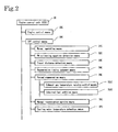
- the forced regeneration control relating to the above described engine cooling water temperature Tw can be performed in accordance with the control flow shown in Fig. 3 .
- the control flow in Fig. 3 is shown as a control flow to be called when the forced regeneration of the DPF device 13 is performed by the forced regeneration means 35C in accordance with the manual regeneration in step S27 or automatic traveling regeneration in step S33 in Fig. 5 .
- step S11 When the control flow is called and started, regeneration mode is checked to judge whether it is in a manual regeneration or in an automatic traveling regeneration in step S11.
- the engine cooling water temperature Tw is checked in step S12. That is, when the engine cooling water temperature Tw is lower than the predetermined first judgment water temperature Tw1, the forced regeneration means 35C is actuated in step S13, and when the temperature Tw is higher than the temperature Tw1, the actuation of the forced regeneration means 35C is interrupted in step S14.
- step S13 only the exhaust gas temperature raising control according to the first-stage multi injection is performed when an exhaust gas temperature is lower than a predetermined judgment exhaust gas temperature.
- the multi injection progresses to the second stage to further perform exhaust gas temperature raising control.
- this exhaust gas temperature raising control is the unburned fuel addition control by post injection in addition to the exhaust gas temperature raising control by multi injection.
- the forced regeneration control is performed for a predetermined control time ⁇ tc relating to the interval of checking of the regeneration mode or the interval of checking of the engine cooling water temperature Tw and the step goes to step S18.
- step S12 when the engine cooling water temperature Tw is equal to or higher than the predetermined first judgment water temperature Tw1, after the forced regeneration control such as the multi injection and the post injection in step S14 is interrupted, and the predetermined control time ⁇ tc elapses, the step goes to S18.
- the engine cooling water temperature Tw is checked in step S15. That is, when engine cooling water temperature Tw is lower than the predetermined second judgment water temperature Tw2, the forced regeneration control means 35C is actuated by the automatic traveling regeneration in step S16. When the temperature Tw is higher than the temperature Tw2, the actuation of the forced regeneration means 35C is interrupted in step S17. Because the cooling water temperature Tw easily rises during traveling, more appropriate regeneration control is performed by setting the predetermined second judgment water temperature Tw2 during automatic traveling regeneration to lower than the predetermined first judgment water temperature Tw1.
- step S15 when the engine cooling water temperature Tw is not less than the predetermined second judgment water temperature tw2, step S17 is started to interrupt the forced regeneration of multiple injection and post injection and step S18 is started after the predetermined control time ⁇ tc is elapsed.
- step S18 it is checked whether regeneration control is completed. This checking is performed depending on whether the DPF front-rear pressure difference ⁇ Pm becomes lower or not than a predetermined completion judgment pressure difference or whether the forced regeneration execution accumulated time passes the predetermined completion judgment time.
- step S18 when it is judged that regeneration control is not completed, the step returns to step S11 and steps S11 to S18 are repeated. Moreover, when it is judged in step S18 that the regeneration control is completed, the regeneration control is terminated and the step returns.
- the above explanation deals with the example of a DPF device in the exhaust gas purification system realized as a DPF device providing an oxidation catalyst on the upstream side of the filter while also making a catalyst supported on the filter; however, the present invention is not restricted to this embodiment.
- the continuous regeneration-type DPF device may also be of the type not supporting a catalyst on the filter, making an oxidation catalyst supported on the filter or providing an oxidation catalyst on the upstream side of the filter, etc.
Landscapes
- Engineering & Computer Science (AREA)
- Chemical & Material Sciences (AREA)
- Combustion & Propulsion (AREA)
- Mechanical Engineering (AREA)
- General Engineering & Computer Science (AREA)
- Processes For Solid Components From Exhaust (AREA)
- Electrical Control Of Air Or Fuel Supplied To Internal-Combustion Engine (AREA)
- Filtering Of Dispersed Particles In Gases (AREA)
- Exhaust Gas Treatment By Means Of Catalyst (AREA)
- Control Of Throttle Valves Provided In The Intake System Or In The Exhaust System (AREA)
- Exhaust Gas After Treatment (AREA)
Applications Claiming Priority (2)
| Application Number | Priority Date | Filing Date | Title |
|---|---|---|---|
| JP2004113375A JP4161931B2 (ja) | 2004-04-07 | 2004-04-07 | 排気ガス浄化システムの制御方法及び排気ガス浄化システム |
| JP2004113375 | 2004-04-07 |
Publications (3)
| Publication Number | Publication Date |
|---|---|
| EP1584807A2 EP1584807A2 (en) | 2005-10-12 |
| EP1584807A3 EP1584807A3 (en) | 2007-05-09 |
| EP1584807B1 true EP1584807B1 (en) | 2013-05-08 |
Family
ID=34909509
Family Applications (1)
| Application Number | Title | Priority Date | Filing Date |
|---|---|---|---|
| EP05102139.2A Ceased EP1584807B1 (en) | 2004-04-07 | 2005-03-18 | Control method for an exhaust gas purification system and an exhaust gas purification system |
Country Status (4)
| Country | Link |
|---|---|
| US (1) | US7168244B2 (ja) |
| EP (1) | EP1584807B1 (ja) |
| JP (1) | JP4161931B2 (ja) |
| CN (1) | CN100549372C (ja) |
Families Citing this family (27)
| Publication number | Priority date | Publication date | Assignee | Title |
|---|---|---|---|---|
| JP3824003B2 (ja) * | 2005-02-24 | 2006-09-20 | いすゞ自動車株式会社 | 排気ガス浄化システム |
| JP3988785B2 (ja) | 2006-02-01 | 2007-10-10 | いすゞ自動車株式会社 | 排気ガス浄化システムの制御方法及び排気ガス浄化システム |
| JP4483832B2 (ja) * | 2006-06-16 | 2010-06-16 | トヨタ自動車株式会社 | Pmトラッパの故障検出システム |
| SE0700235L (sv) | 2007-01-31 | 2008-08-01 | Scania Cv Ab | Metod och system för provning av ett fordonsavgasutsläppssystem |
| JP4100451B1 (ja) * | 2007-03-02 | 2008-06-11 | いすゞ自動車株式会社 | 排気ガス浄化方法及び排気ガス浄化システム |
| JP4928335B2 (ja) | 2007-04-17 | 2012-05-09 | 日野自動車株式会社 | 排気浄化装置 |
| US8316638B2 (en) * | 2007-12-12 | 2012-11-27 | GM Global Technology Operations LLC | Control system for a particulate matter filter |
| US8322132B2 (en) * | 2008-04-30 | 2012-12-04 | Perkins Engines Company Limited | Exhaust treatment system implementing regeneration control |
| WO2010073876A1 (ja) * | 2008-12-24 | 2010-07-01 | トヨタ自動車株式会社 | 車両の制御装置 |
| US8061129B2 (en) * | 2009-01-30 | 2011-11-22 | Thermo King Corporation and Donaldson Company, Inc. | System and method to regenerate a diesel particulate filter |
| US8350682B2 (en) * | 2009-06-12 | 2013-01-08 | Mack Trucks, Inc. | DPF warning system |
| JP5325090B2 (ja) * | 2009-12-25 | 2013-10-23 | 三菱重工業株式会社 | 内燃機関の排気浄化装置 |
| US8347612B2 (en) * | 2010-03-19 | 2013-01-08 | GM Global Technology Operations LLC | Method and apparatus for regenerating a particulate filter system |
| JP2011226356A (ja) * | 2010-04-19 | 2011-11-10 | Volvo Powertrain Ab | ディーゼルエンジンの排気浄化装置 |
| US10371027B2 (en) * | 2010-04-30 | 2019-08-06 | Yanmar Co., Ltd. | Exhaust gas purification system of working machine |
| JP5533260B2 (ja) * | 2010-05-25 | 2014-06-25 | いすゞ自動車株式会社 | Dpfシステム |
| JP5682159B2 (ja) * | 2010-06-30 | 2015-03-11 | マツダ株式会社 | ディーゼルエンジン |
| KR101251517B1 (ko) * | 2010-12-09 | 2013-04-05 | 현대자동차주식회사 | 배기가스 후처리 시스템 |
| JP5864901B2 (ja) * | 2011-05-19 | 2016-02-17 | 日野自動車株式会社 | パティキュレートフィルタの手動再生方法 |
| US9534551B2 (en) * | 2011-09-27 | 2017-01-03 | Kubota Corporation | Working machine |
| JP6011224B2 (ja) * | 2012-10-09 | 2016-10-19 | いすゞ自動車株式会社 | 排気ガス浄化システム及び排気ガス浄化方法 |
| US9879586B2 (en) * | 2012-12-07 | 2018-01-30 | Toyota Jidosha Kabushiki Kaisha | Abnormality detection device for exhaust gas purification apparatus |
| DE102013222022A1 (de) * | 2013-10-30 | 2015-04-30 | Robert Bosch Gmbh | Verfahren und Vorrichtung zur Erkennung einer Wasserdurchfahrt mittels Abstandssensoren |
| JP6365513B2 (ja) * | 2015-11-20 | 2018-08-01 | コベルコ建機株式会社 | 建設機械 |
| CN106640304A (zh) * | 2017-01-25 | 2017-05-10 | 中国第汽车股份有限公司 | 柴油机颗粒补集系统的再生方法 |
| CN109838296B (zh) * | 2017-11-29 | 2021-09-28 | 上海汽车集团股份有限公司 | 具有驾驶者引导功能的颗粒过滤器再生管理方法和系统 |
| CN115013129B (zh) * | 2022-06-16 | 2023-08-08 | 江铃汽车股份有限公司 | 一种防止柴油机尾气排放物pn超标的控制策略 |
Family Cites Families (13)
| Publication number | Priority date | Publication date | Assignee | Title |
|---|---|---|---|---|
| DE3580606D1 (de) * | 1984-03-31 | 1991-01-03 | Mitsubishi Motors Corp | Regenerationssystem fuer eine diesel-partikel-oxydierungseinrichtung. |
| US5121601A (en) * | 1986-10-21 | 1992-06-16 | Kammel Refaat A | Diesel engine exhaust oxidizer |
| GB2239407B (en) * | 1989-12-27 | 1994-10-12 | Nissan Motor | Exhaust gas purifying device for an internal combustion engine |
| KR100287049B1 (ko) * | 1995-10-30 | 2001-05-02 | 와다 아끼히로 | 내연기관용 배기 가스 정화 장치 |
| DE50000400D1 (de) * | 2000-11-03 | 2002-09-26 | Ford Global Tech Inc | Regelungsanordnung und Verfahren zur Unterbrechung der Regeneration eines Partikelfilters eines Dieselmotors |
| DE60226204T2 (de) * | 2001-09-07 | 2009-05-14 | Mitsubishi Jidosha Kogyo K.K. | Vorrichtung zur Steuerung der Abgasabgabe eines Motors |
| JP4042399B2 (ja) * | 2001-12-12 | 2008-02-06 | 三菱自動車工業株式会社 | 排気浄化装置 |
| JP4165082B2 (ja) | 2002-02-13 | 2008-10-15 | 日産自動車株式会社 | 排気浄化装置 |
| JP3870815B2 (ja) * | 2002-03-29 | 2007-01-24 | 日産自動車株式会社 | 内燃機関の排気浄化装置 |
| JP4007085B2 (ja) * | 2002-06-13 | 2007-11-14 | 株式会社デンソー | 内燃機関の排ガス浄化装置 |
| JP3823923B2 (ja) * | 2003-01-16 | 2006-09-20 | 日産自動車株式会社 | 排気浄化装置 |
| JP3846452B2 (ja) * | 2003-05-20 | 2006-11-15 | マツダ株式会社 | エンジンの制御装置 |
| JP4333289B2 (ja) * | 2003-09-03 | 2009-09-16 | いすゞ自動車株式会社 | 排気ガス浄化システム |
-
2004
- 2004-04-07 JP JP2004113375A patent/JP4161931B2/ja not_active Expired - Fee Related
-
2005
- 2005-03-18 EP EP05102139.2A patent/EP1584807B1/en not_active Ceased
- 2005-03-18 US US11/082,832 patent/US7168244B2/en not_active Expired - Lifetime
- 2005-03-31 CN CNB2005100600853A patent/CN100549372C/zh not_active Expired - Fee Related
Also Published As
| Publication number | Publication date |
|---|---|
| EP1584807A3 (en) | 2007-05-09 |
| JP4161931B2 (ja) | 2008-10-08 |
| JP2005299418A (ja) | 2005-10-27 |
| EP1584807A2 (en) | 2005-10-12 |
| US20060000201A1 (en) | 2006-01-05 |
| US7168244B2 (en) | 2007-01-30 |
| CN100549372C (zh) | 2009-10-14 |
| CN1680686A (zh) | 2005-10-12 |
Similar Documents
| Publication | Publication Date | Title |
|---|---|---|
| EP1584807B1 (en) | Control method for an exhaust gas purification system and an exhaust gas purification system | |
| EP1584808B1 (en) | Control method for an exhaust gas purification system and an exhaust gas purification system | |
| EP1582720B1 (en) | Control method for an exhaust gas purification system and an exhaust gas purification system | |
| US7845165B2 (en) | Exhaust gas purifying system | |
| EP1584802B1 (en) | Control method for an exhaust gas purification system and an exhaust gas purification system | |
| EP1584806B1 (en) | Control method for an exhaust gas purification system and an exhaust gas purification system | |
| JP4169076B2 (ja) | 排気ガス浄化システムの制御方法及び排気ガス浄化システム | |
| EP1905991B1 (en) | Control method of exhaust gas purification system and exhaust gas purification system | |
| CN101583778B (zh) | 废气净化方法及废气净化系统 | |
| CN101466921B (zh) | 排气气体净化方法及排气气体净化系统 | |
| US7721534B2 (en) | Control method for an exhaust gas purification system and an exhaust gas purification system | |
| EP1905992B1 (en) | Method of controlling exhaust gas purification system, and exhaust gas purification system | |
| EP1978219B1 (en) | Exhaust gas purification method and exhaust gas purification system | |
| JP3979437B1 (ja) | 排気ガス浄化システムの制御方法及び排気ガス浄化システム | |
| JP4466158B2 (ja) | 排気ガス浄化システムの制御方法及び排気ガス浄化システム | |
| JP4517682B2 (ja) | 排気ガス浄化システム |
Legal Events
| Date | Code | Title | Description |
|---|---|---|---|
| PUAI | Public reference made under article 153(3) epc to a published international application that has entered the european phase |
Free format text: ORIGINAL CODE: 0009012 |
|
| AK | Designated contracting states |
Kind code of ref document: A2 Designated state(s): AT BE BG CH CY CZ DE DK EE ES FI FR GB GR HU IE IS IT LI LT LU MC NL PL PT RO SE SI SK TR |
|
| AX | Request for extension of the european patent |
Extension state: AL BA HR LV MK YU |
|
| PUAL | Search report despatched |
Free format text: ORIGINAL CODE: 0009013 |
|
| AK | Designated contracting states |
Kind code of ref document: A3 Designated state(s): AT BE BG CH CY CZ DE DK EE ES FI FR GB GR HU IE IS IT LI LT LU MC NL PL PT RO SE SI SK TR |
|
| AX | Request for extension of the european patent |
Extension state: AL BA HR LV MK YU |
|
| 17P | Request for examination filed |
Effective date: 20070927 |
|
| 17Q | First examination report despatched |
Effective date: 20071108 |
|
| AKX | Designation fees paid |
Designated state(s): DE FR GB IT |
|
| GRAP | Despatch of communication of intention to grant a patent |
Free format text: ORIGINAL CODE: EPIDOSNIGR1 |
|
| GRAS | Grant fee paid |
Free format text: ORIGINAL CODE: EPIDOSNIGR3 |
|
| GRAA | (expected) grant |
Free format text: ORIGINAL CODE: 0009210 |
|
| RIN1 | Information on inventor provided before grant (corrected) |
Inventor name: MASHIKO, TATSUO Inventor name: SATO, HITOSHI Inventor name: TSUCHIDA, MINORU Inventor name: IIZUKA, AKIRA Inventor name: UCHIDA, NAOMI |
|
| AK | Designated contracting states |
Kind code of ref document: B1 Designated state(s): DE FR GB IT |
|
| REG | Reference to a national code |
Ref country code: GB Ref legal event code: FG4D |
|
| REG | Reference to a national code |
Ref country code: DE Ref legal event code: R096 Ref document number: 602005039456 Country of ref document: DE Effective date: 20130711 |
|
| PG25 | Lapsed in a contracting state [announced via postgrant information from national office to epo] |
Ref country code: IT Free format text: LAPSE BECAUSE OF FAILURE TO SUBMIT A TRANSLATION OF THE DESCRIPTION OR TO PAY THE FEE WITHIN THE PRESCRIBED TIME-LIMIT Effective date: 20130508 |
|
| PLBE | No opposition filed within time limit |
Free format text: ORIGINAL CODE: 0009261 |
|
| STAA | Information on the status of an ep patent application or granted ep patent |
Free format text: STATUS: NO OPPOSITION FILED WITHIN TIME LIMIT |
|
| 26N | No opposition filed |
Effective date: 20140211 |
|
| REG | Reference to a national code |
Ref country code: DE Ref legal event code: R097 Ref document number: 602005039456 Country of ref document: DE Effective date: 20140211 |
|
| REG | Reference to a national code |
Ref country code: FR Ref legal event code: PLFP Year of fee payment: 12 |
|
| REG | Reference to a national code |
Ref country code: FR Ref legal event code: PLFP Year of fee payment: 13 |
|
| PGFP | Annual fee paid to national office [announced via postgrant information from national office to epo] |
Ref country code: FR Payment date: 20170213 Year of fee payment: 13 Ref country code: DE Payment date: 20170314 Year of fee payment: 13 |
|
| PGFP | Annual fee paid to national office [announced via postgrant information from national office to epo] |
Ref country code: GB Payment date: 20170315 Year of fee payment: 13 |
|
| REG | Reference to a national code |
Ref country code: DE Ref legal event code: R119 Ref document number: 602005039456 Country of ref document: DE |
|
| GBPC | Gb: european patent ceased through non-payment of renewal fee |
Effective date: 20180318 |
|
| PG25 | Lapsed in a contracting state [announced via postgrant information from national office to epo] |
Ref country code: DE Free format text: LAPSE BECAUSE OF NON-PAYMENT OF DUE FEES Effective date: 20181002 |
|
| PG25 | Lapsed in a contracting state [announced via postgrant information from national office to epo] |
Ref country code: GB Free format text: LAPSE BECAUSE OF NON-PAYMENT OF DUE FEES Effective date: 20180318 |
|
| PG25 | Lapsed in a contracting state [announced via postgrant information from national office to epo] |
Ref country code: FR Free format text: LAPSE BECAUSE OF NON-PAYMENT OF DUE FEES Effective date: 20180331 |