EP1584506B1 - Klimaanlage mit einer Vorrichtung zum Ablassen des Kältemittels aus dem Kältekreislauf - Google Patents
Klimaanlage mit einer Vorrichtung zum Ablassen des Kältemittels aus dem Kältekreislauf Download PDFInfo
- Publication number
- EP1584506B1 EP1584506B1 EP05007448A EP05007448A EP1584506B1 EP 1584506 B1 EP1584506 B1 EP 1584506B1 EP 05007448 A EP05007448 A EP 05007448A EP 05007448 A EP05007448 A EP 05007448A EP 1584506 B1 EP1584506 B1 EP 1584506B1
- Authority
- EP
- European Patent Office
- Prior art keywords
- refrigerant
- evaporator
- refrigerant passage
- valve
- refrigeration system
- Prior art date
- Legal status (The legal status is an assumption and is not a legal conclusion. Google has not performed a legal analysis and makes no representation as to the accuracy of the status listed.)
- Expired - Lifetime
Links
- 239000003507 refrigerant Substances 0.000 title claims description 112
- 238000005057 refrigeration Methods 0.000 title claims description 23
- XEEYBQQBJWHFJM-UHFFFAOYSA-N Iron Chemical group [Fe] XEEYBQQBJWHFJM-UHFFFAOYSA-N 0.000 claims description 25
- 238000006073 displacement reaction Methods 0.000 claims description 6
- 230000000903 blocking effect Effects 0.000 claims description 4
- 238000001514 detection method Methods 0.000 claims description 2
- 230000009977 dual effect Effects 0.000 claims 1
- 230000033001 locomotion Effects 0.000 claims 1
- CURLTUGMZLYLDI-UHFFFAOYSA-N Carbon dioxide Chemical compound O=C=O CURLTUGMZLYLDI-UHFFFAOYSA-N 0.000 description 16
- 239000002184 metal Substances 0.000 description 9
- 229910052751 metal Inorganic materials 0.000 description 9
- 239000010409 thin film Substances 0.000 description 9
- 229910002092 carbon dioxide Inorganic materials 0.000 description 8
- 239000001569 carbon dioxide Substances 0.000 description 8
- 239000007788 liquid Substances 0.000 description 6
- NPNPZTNLOVBDOC-UHFFFAOYSA-N 1,1-difluoroethane Chemical compound CC(F)F NPNPZTNLOVBDOC-UHFFFAOYSA-N 0.000 description 4
- 239000007789 gas Substances 0.000 description 4
- 238000001704 evaporation Methods 0.000 description 3
- 238000000926 separation method Methods 0.000 description 3
- 206010003497 Asphyxia Diseases 0.000 description 2
- ATUOYWHBWRKTHZ-UHFFFAOYSA-N Propane Chemical compound CCC ATUOYWHBWRKTHZ-UHFFFAOYSA-N 0.000 description 2
- 230000032683 aging Effects 0.000 description 2
- 238000004378 air conditioning Methods 0.000 description 2
- 238000007664 blowing Methods 0.000 description 2
- 238000010586 diagram Methods 0.000 description 2
- 238000011144 upstream manufacturing Methods 0.000 description 2
- 238000010792 warming Methods 0.000 description 2
- LVGUZGTVOIAKKC-UHFFFAOYSA-N 1,1,1,2-tetrafluoroethane Chemical compound FCC(F)(F)F LVGUZGTVOIAKKC-UHFFFAOYSA-N 0.000 description 1
- 206010000369 Accident Diseases 0.000 description 1
- 206010021143 Hypoxia Diseases 0.000 description 1
- 230000005856 abnormality Effects 0.000 description 1
- 230000001154 acute effect Effects 0.000 description 1
- 239000001273 butane Substances 0.000 description 1
- 230000001419 dependent effect Effects 0.000 description 1
- 230000008020 evaporation Effects 0.000 description 1
- 239000007792 gaseous phase Substances 0.000 description 1
- 239000007791 liquid phase Substances 0.000 description 1
- IJDNQMDRQITEOD-UHFFFAOYSA-N n-butane Chemical compound CCCC IJDNQMDRQITEOD-UHFFFAOYSA-N 0.000 description 1
- OFBQJSOFQDEBGM-UHFFFAOYSA-N n-pentane Natural products CCCCC OFBQJSOFQDEBGM-UHFFFAOYSA-N 0.000 description 1
- 238000012856 packing Methods 0.000 description 1
- 238000005192 partition Methods 0.000 description 1
- 239000012071 phase Substances 0.000 description 1
- 239000001294 propane Substances 0.000 description 1
- 239000011347 resin Substances 0.000 description 1
- 229920005989 resin Polymers 0.000 description 1
- 230000029058 respiratory gaseous exchange Effects 0.000 description 1
- 238000003466 welding Methods 0.000 description 1
Images
Classifications
-
- B—PERFORMING OPERATIONS; TRANSPORTING
- B60—VEHICLES IN GENERAL
- B60H—ARRANGEMENTS OF HEATING, COOLING, VENTILATING OR OTHER AIR-TREATING DEVICES SPECIALLY ADAPTED FOR PASSENGER OR GOODS SPACES OF VEHICLES
- B60H1/00—Heating, cooling or ventilating [HVAC] devices
- B60H1/32—Cooling devices
- B60H1/3204—Cooling devices using compression
- B60H1/3225—Cooling devices using compression characterised by safety arrangements, e.g. compressor anti-seizure means or by signalling devices
-
- B—PERFORMING OPERATIONS; TRANSPORTING
- B60—VEHICLES IN GENERAL
- B60H—ARRANGEMENTS OF HEATING, COOLING, VENTILATING OR OTHER AIR-TREATING DEVICES SPECIALLY ADAPTED FOR PASSENGER OR GOODS SPACES OF VEHICLES
- B60H1/00—Heating, cooling or ventilating [HVAC] devices
- B60H1/00642—Control systems or circuits; Control members or indication devices for heating, cooling or ventilating devices
- B60H1/00978—Control systems or circuits characterised by failure of detection or safety means; Diagnostic methods
-
- F—MECHANICAL ENGINEERING; LIGHTING; HEATING; WEAPONS; BLASTING
- F25—REFRIGERATION OR COOLING; COMBINED HEATING AND REFRIGERATION SYSTEMS; HEAT PUMP SYSTEMS; MANUFACTURE OR STORAGE OF ICE; LIQUEFACTION SOLIDIFICATION OF GASES
- F25B—REFRIGERATION MACHINES, PLANTS OR SYSTEMS; COMBINED HEATING AND REFRIGERATION SYSTEMS; HEAT PUMP SYSTEMS
- F25B2341/00—Details of ejectors not being used as compression device; Details of flow restrictors or expansion valves
- F25B2341/06—Details of flow restrictors or expansion valves
- F25B2341/068—Expansion valves combined with a sensor
- F25B2341/0683—Expansion valves combined with a sensor the sensor is disposed in the suction line and influenced by the temperature or the pressure of the suction gas
-
- F—MECHANICAL ENGINEERING; LIGHTING; HEATING; WEAPONS; BLASTING
- F25—REFRIGERATION OR COOLING; COMBINED HEATING AND REFRIGERATION SYSTEMS; HEAT PUMP SYSTEMS; MANUFACTURE OR STORAGE OF ICE; LIQUEFACTION SOLIDIFICATION OF GASES
- F25B—REFRIGERATION MACHINES, PLANTS OR SYSTEMS; COMBINED HEATING AND REFRIGERATION SYSTEMS; HEAT PUMP SYSTEMS
- F25B2500/00—Problems to be solved
- F25B2500/06—Damage
-
- F—MECHANICAL ENGINEERING; LIGHTING; HEATING; WEAPONS; BLASTING
- F25—REFRIGERATION OR COOLING; COMBINED HEATING AND REFRIGERATION SYSTEMS; HEAT PUMP SYSTEMS; MANUFACTURE OR STORAGE OF ICE; LIQUEFACTION SOLIDIFICATION OF GASES
- F25B—REFRIGERATION MACHINES, PLANTS OR SYSTEMS; COMBINED HEATING AND REFRIGERATION SYSTEMS; HEAT PUMP SYSTEMS
- F25B2500/00—Problems to be solved
- F25B2500/18—Optimization, e.g. high integration of refrigeration components
-
- F—MECHANICAL ENGINEERING; LIGHTING; HEATING; WEAPONS; BLASTING
- F25—REFRIGERATION OR COOLING; COMBINED HEATING AND REFRIGERATION SYSTEMS; HEAT PUMP SYSTEMS; MANUFACTURE OR STORAGE OF ICE; LIQUEFACTION SOLIDIFICATION OF GASES
- F25B—REFRIGERATION MACHINES, PLANTS OR SYSTEMS; COMBINED HEATING AND REFRIGERATION SYSTEMS; HEAT PUMP SYSTEMS
- F25B49/00—Arrangement or mounting of control or safety devices
- F25B49/005—Arrangement or mounting of control or safety devices of safety devices
Definitions
- the invention relates to a refrigeration system, particularly for use in an automotive air conditioner containing a refrigerant gas harmful to a human body.
- a typical automotive refrigeration system is known from JP 2002-147 898 A , which is considered as the closest prior art. It comprises among other components an evaporator for evaporating expanded refrigerant and for returning the refrigerant to the compressor.
- the refrigerant as used is a CFC substitute (HFC-134a)
- HFC-134a CFC substitute
- other refrigerants with a small global warming potential like e.g. carbon dioxide, HFC-152a, butane, and propane, recently have come to be demanded instead in view of global warming.
- a CFC substitute HFC-134a
- carbon dioxide is used in the case of the evaporator disposed in a space leading to a vehicle compartment or in a piping disposed in the vehicle compartment, there is a danger of suffocation of vehicle occupants due to oxygen deficiency, whereas when an inflammable gas, such as HFC-152a, is used as refrigerant, in case of the above-mentioned event, there is a possibility of the inflammable gas catching a fire to set the vehicle on fire, causing serious influence on the vehicle occupants, when the evaporator is broken or cracked due to aging or in an accident such that refrigerant will be released into the vehicle compartment.
- the expansion device is formed with a valve seat in the first refrigerant passage.
- a ball-shaped valve element is located upstream of the valve seat and is loaded by a spring in valve closing direction.
- a shaft is transmitting displacements of the power element, caused by the temperature and pressure of refrigerant in the second refrigerant passage, through the valve seat and counter to the force of the spring to the valve element, for controlling the flow rate of refrigerant through the first refrigerant passage according to temperature and pressure of the refrigerant in the second refrigerant passage.
- the vehicle air-conditioning system contains an electrically operated release-to-atmosphere device in a piping on a suction side of the compressor.
- the vehicle air-conditioning system comprises a check valve in a suction line between the evaporator and an accumulator-dehydrator.
- a thermal expansion device is disposed in the refrigerant line between the condenser and the evaporator.
- the opening and closing section of the expansion device is closed to isolate the evaporator from the high-pressure first refrigerant passage.
- the release-to-atmosphere device is caused to operate to open the piping on the suction side of the compressor to the atmosphere to dispose refrigerant in the low-pressure piping including the evaporator to the outside of the vehicle compartment. This prevents the all refrigerant in the refrigeration cycle is discharged into the vehicle compartment. The safety of vehicle occupants thus is ensured even in case of accidents.
- the refrigeration system uses a normally-closed electromagnetic valve for the opening and closing section of the expansion device. Even in cases where the power supply from a battery is cut off when the vehicle falls into a state where the evaporator can be broken, the possibility remains to positively isolate the evaporator from the high-pressure piping by the then closed valve.
- the release-to-atmosphere device is capable of holding itself in the state open to the atmosphere even when in a de-energized state after first being electrically operated to open to the atmosphere. Refrigerant in the low-pressure piping will be released into the atmosphere even after the power supply is cut off.
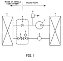
- the refrigeration system in Fig. 1 comprises a compressor 1 that compresses refrigerant, a condenser 2 that condenses the compressed refrigerant, a receiver/dryer 3 that separates the condensed refrigerant into gaseous and liquid phases while temporarily storing the refrigerant circulating through the refrigeration cycle, an expansion device 4 that throttles and expands liquid refrigerant obtained by gas/liquid separation, and an evaporator 5 that evaporates the expanded refrigerant and returns the refrigerant to the compressor.
- a release-to-atmosphere device 6 is disposed in piping on the suction side of the compressor 1 .
- the expansion device 4 comprises an electromagnetic valve 7 that opens and closes piping on the inlet side of the evaporator 5, an expansion valve 8 that throttles and expands liquid refrigerant, and a check valve 9 disposed in piping on the outlet side of the evaporator 5.
- the electromagnetic valve 7 forms an electrically-driven opening and closing section that opens when de-energized and that closes when energized.
- the check valve 9 forms a backflow-preventing section that prevents backflow of refrigerant from the compressor 1 to the evaporator 5.
- the release-to-atmosphere device 6 holds itself in the state open to the atmosphere after being electrically operated.
- the compressor 1, the condenser 2, the receiver/dryer 3, and the release-to-atmosphere device 6 are arranged in an engine room of an automotive vehicle.
- the evaporator 5 is disposed in a space leading to the vehicle compartment.
- the expansion device 4 e.g. is disposed at a partition wall separating between the compartment and the engine room.
- the electromagnetic valve 7 of the expansion device 4 When the automotive air conditioner is operated, first, the electromagnetic valve 7 of the expansion device 4 is fully opened.
- the compressed refrigerant enters the receiver/dryer 3 after being condensed by the condenser 2, and is subjected to gas-liquid separation by the receiver/dryer 3.
- the liquid refrigerant phase obtained by the gas-liquid separation passes through the electromagnetic valve 7 to enter the expansion valve 8, where it is throttled and expanded to enter the evaporator 5.
- the refrigerant passes through the check valve 9 to return to the compressor 1.
- the electromagnetic valve 7 is closed to block a refrigerant passage between the receiver/dryer 3 and the expansion valve 8. This prevents that compressed refrigerant from the compressor 1 will enter the expansion valve 8 and then the evaporator 5.
- the compressor 1 has stopped and ceased to produce suction of refrigerant, and a not shown fan stops blowing air to the evaporator 5 to stop evaporation of refrigerant in the evaporator 5, the pressure present in the evaporator 5 becomes lower than the pressure on the suction side of the compressor 1.
- the check valve 9 is closed by the pressure difference to prevent refrigerant in the piping on the suction side of the compressor 1 from flowing back into the evaporator 5.
- the release-to-atmosphere device 6 is operated, and if the automotive air conditioner should be in operation, energization of the electronic magnet valve 7 is simultaneously stopped. The electromagnetic valve 7 then will close and will stop any refrigerant flow to the evaporator 5 through the high-pressure piping.
- the release-to-atmosphere device 6 will open low-pressure piping on the suction side of the compressor 1 to the atmosphere to thereby release refrigerant from the refrigeration cycle into the atmosphere.
- a high-pressure refrigerant flow from the evaporator 5 into the compartment is prevented and a refrigerant flow from the piping on the low-pressure side is also prevented from the evaporator 5 into the compartment.
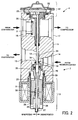
- Fig. 2 simultaneously shows the electromagnetic closing function of the expansion device for blocking a low-pressure refrigerant passage and a state of a function thereof as a conventional expansion device having its opening controlled (right-hand side: a valve element and movable parts of a solenoid in a valve-closed state during de-energization of the expansion device), and a state operating as an expansion valve operation during energization of the expansion device (left-hand side).
- the expansion device 4 comprises a body block 11 housing the electromagnetic valve 7 that forms the electrically-operated opening and closing section, and respective valve elements of the check valve 9 that forms the backflow-preventing section and the expansion valve 8, a power element 12 that senses temperature and pressure of refrigerant returning from the evaporator 5, and a solenoid 13 that switches the electromagnetic valve 7 between its electromagnetic closing function and its expansion valve function.
- the body block 11 has a side port 14 for receiving high-temperature, high-pressure refrigerant from the condenser 2, a port 15 for supplying low-temperature, low-pressure refrigerant subjected to adiabatic expansion by the expansion device 4 to the evaporator 5, a port 16 for receiving refrigerant returned from the evaporator 5, and a port 17 for sending the refrigerant received through the port 16 to the compressor 1.
- a valve seat 18 is integrally formed with the body block 11.
- a shaft 19 extending through a valve hole forming a valve seat 18, a valve element guide 20 having the same diameter as the valve hole, and a shaft 21 forming a drive shaft of the solenoid 13.
- An upper end of the shaft 19 is in abutment with a centre disk 23 disposed on a lower side of a diaphragm 22 of the power element 12.
- a dual-purpose valve element 24 extends through the valve seat 18 from an upstream side thereof such that it can be brought into contact with the valve seat 18 and out of contact therefrom by being guided along the shaft 19 and the valve element guide 20. With this configuration, a gap between the valve seat 18 and the dual-purpose valve element 24 forms a variable orifice for throttling high-pressure refrigerant, whereby refrigerant is throttled and expanded when passing through the variable orifice.
- the dual-purpose valve element 24 is held on a first iron core 25 of the solenoid 13 serving as a movable iron core.
- the first iron core 25 is disposed axially movable while being guided by a shaft 21.
- a lower end of the shaft 21 is supported by a bearing 27 formed in an iron core case 26 of the solenoid 13.
- the second iron core 28 is urged upward by a spring 29. This spring 29 urges the shaft 19 such that the shaft 19 remains in constant contact with the power element 12.
- a spring 30 is interposed between the first and second iron cores 25, 28.
- This spring 30 urges the first iron core 25 in a direction away from the second iron core 28 to allow to maintain the fully-closed state of the valve seat 18 by constantly seating the dual-purpose valve element 24 held by the first iron core 25 on the valve seat 18.
- an electromagnetic coil 31 outside the iron core case 26, there is arranged an electromagnetic coil 31.
- the electromagnetic coil 31 is energized to cause the first iron core 25 and the second iron core 28 to attract each other, whereby the dual-purpose valve element 24 and the shaft 19 are electromagnetically coupled to transmit the displacement of the diaphragm 22 of the power element 12 to the dual-purpose valve element 24.
- the dual-purpose valve element 24 has an annular valve sheet 32 at a portion via which it is seated on the valve seat 18. In the fully-closed state caused by the urging force of the spring 30 when the solenoid 13 is de-energized, the valve sheet 32 seals between the dual-purpose valve element 24 and the valve seat 18, to substantially completely stop the flow of high-pressure refrigerant.
- a V packing 33 is disposed in a space formed between the dual-purpose valve element 24 and the first iron core 25, to prevent any internal leakage in the fully-closed state when high-pressure refrigerant introduced to the valve element guide 20 via a gap between the first iron core 25 and the shaft 21 would flow downstream of the valve section through a gap between the dual-purpose valve element 24 and the valve element guide 20 and between the dual-purpose valve element 24 and the shaft 19.
- the check valve 9 is disposed in a low-pressure refrigerant passage between the port 16 that receives refrigerant returned from the evaporator 5 and the port 17 that returns the refrigerant to the compressor 1.
- the check valve 9 is disposed in a central second refrigerant passage communicating with a chamber below the diaphragm 22 provided for the power element 12, for sensing the temperature and pressure of refrigerant.
- the check valve 9 is formed integrally with legs, which are guided in valve-opening and valve closing directions by the inner wall of the refrigerant passage of the port 16.
- the check valve element e.g. a plate or disk
- the check valve element is urged by a weak spring, not shown, in valve-closing direction.
- the check valve 9 has a flexible annular valve sheet 35 at a portion via which it is seated on a counter surface surrounding the mouth of the passage to the port 16. When the pressure in the evaporator 5 becomes lower than the pressure on the suction side of the compressor 1, the check valve 9 will close to isolate the evaporator 5 from the compressor 1.
- the solenoid 13 Since the solenoid 13 is de-energized when the air conditioner is in stoppage, the first iron core 25 is urged by the spring 30 in a direction away from the second iron core 28. Then the dual-purpose valve element 24 held by the first iron core 25 seated on the valve seat 18.
- the solenoid 13 is energized.
- the first and second iron cores 25, 28 are attracted to each other, so that the dual-purpose valve element 24 is indirectly fixed to the shaft 19 that transmits the displacement of the diaphragm 22.
- the dual-purpose valve element 24 is moved away from the valve seat 18 and high-temperature, high-pressure refrigerant supplied from the receiver/dryer 3 to the port 14 flows through the gap between the dual-purpose valve element 24 and the valve seat 18 into the port 15.
- the high-temperature, high-pressure refrigerant is throttled and expanded into low-temperature, low-pressure refrigerant, and the resulting refrigerant is supplied from the port 15 to the evaporator 5.
- the evaporator 5 causes the refrigerant to evaporate by exchanging heat with air in the compartment, and returns the evaporated refrigerant to the expansion device 4.
- the refrigerant returned from the evaporator 5 is received at the port 16 of the expansion device 4, passes through the central refrigerant passage, and is returned from the port 17 to the compressor 1.
- the power element 12 senses the temperature and pressure of the refrigerant flowing from the evaporator 5, and transmits the displacement of the diaphragm 22 dependent on the temperature and pressure of the refrigerant to the dual-purpose valve element 24 via the shaft 19, the valve element guide 20, the shaft 21, and the first and second iron cores 25 and 28, to thereby control the flow rate of refrigerant.
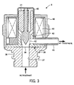
- the release-to-atmosphere device 6 includes in Fig. 3 a body 36 forming a joint for connection to low-pressure piping on the suction side of the compressor 1.
- the body 36 has an axial and central refrigerant inlet passage 37.
- a metal thin film 38 is disposed on an upper surface of the body 36 in a manner blocking the refrigerant inlet passage 37.
- the metal thin film 38 is welded to the body 36 e.g. by laser welding along a concentric circle passing through a point 39 outward of the refrigerant inlet passage 37, whereby the metal thin film 38 is gastightly sealed to the body 36 along the whole circumference.
- a solenoid Disposed above the body 36 is a solenoid forming a thin film-breaking section. More specifically, a piercing rod 40 is disposed in a manner movable forward and backward in a direction perpendicular to the surface of the metal thin film 38. This piercing rod 40 has a tip facing the metal thin film 38. The tip is formed such that it has a pointed shape.
- the piercing rod 40 is rigidly fixed to a movable core 41 of the solenoid.
- the movable core 41 is urged by a spring 42 in a direction away from a fixed core 43.
- the fixed core 43 has an axial hole receiving the piercing rod 40 and the spring 42 and a lower end, in Fig. 3, which is integrally formed with a flange portion protruding radially outward for forming a magnetic circuit and which has at least one horizontal hole above the flange position for permitting refrigerant to escape to the atmosphere.
- a coil 44 is disposed around the outer peripheries of the movable core 41 and the fixed core 43.
- a bobbin for the coil 44 has a container containing the movable core 41 and the fixed core 43, and has a conduit 45 for releasing refrigerant into the atmosphere, the container and the conduit 45 being integrally formed with the bobbin e.g. by a resin.
- This conduit 45 e.g. has a hose connected thereto, to guide refrigerant to a suitable remoter location.
- a yoke 46 for forming the magnetic circuit is disposed outside the coil 44.
- the yoke 46 may be fixed to the body 36 by swaging.
- a pulse current e.g. is supplied to the coil 44.
- the movable core 41 is attracted by the fixed core 43 against the urging force of the spring 42.
- the tip of the piercing rod 40 formed with an acute angle breaks through the metal thin film 38, so that refrigerant in the refrigeration cycle is instantly released into the atmosphere via the conduit 45.
- the movable core 41 When the pulse current ceases to be supplied to the coil 44, the movable core 41 is moved away from the fixed core 43 by the urging force of the spring 42. The piercing rod 40 is pushed back by refrigerant blowing out from the broken metal thin film 38. After that, the release-to-atmosphere device 6 automatically remains in the state open to the atmosphere. This prevents that refrigerant from the refrigeration cycle will reach the vehicle compartment in large or dangerous amounts. This prevents a suffocation accident by the released refrigerant, or a fire accident caused by a fire caught by the released refrigerant.
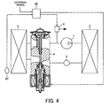
- a refrigerant sensor 47 is disposed in the vicinity of the evaporator 5, for detecting the concentration of refrigerant e.g. in the compartment.
- the output of the refrigerant sensor 47 is connected to the input of a control device 48.
- the output of the control device 48 is connected to both the expansion device 4 and the release-to-atmosphere device 6 .
- the refrigerant sensor 47 is implemented by a sensor that detects carbon dioxide, whereas when HFC-152a is used, the same is implemented by a sensor that detects HFC-152a.
- control device 48 is configured to be capable of receiving an external signal.
- the external signal e.g. is output when a computer mounted on the vehicle detects that the vehicle has fallen into a state in which the evaporator 5 can be seriously damaged.
- the control device 48 When the refrigerant sensor 47 detects an actual release of refrigerant from the evaporator 5, the control device 48, responsive to the detection signal, causes the expansion device 4 and the release-to-atmosphere device 6 to operate. That is, when the air conditioner is in stoppage, the control device 48 does not do anything to the expansion device 4, but when the same is in operation, the control device 48 turns off the power of the electromagnetic valve 7 to block the high-pressure piping to thereby isolate the evaporator 5 from the high-pressure piping.
- the control device 48 supplies pulse current to the release-to-atmosphere device 6 to cause the solenoid thereof to operate, whereby the metal thin film 38 is broken to allow refrigerant in the low-pressure piping to be released into the atmosphere outside the vehicle compartment.
- the electromagnetic valve 7 is similarly closed, and the release-to-atmosphere device 6 is opened to the atmosphere.
Landscapes
- Physics & Mathematics (AREA)
- Thermal Sciences (AREA)
- Engineering & Computer Science (AREA)
- Mechanical Engineering (AREA)
- Air-Conditioning For Vehicles (AREA)
Claims (3)
- Kühlsystem, mit
einem Kompressor (1),
einem Verdampfer (5) in einem zum Inneren eines Fahrzeuginnenraums führenden Raum,
einer Expansionsvorrichtung (4), einschließlich einer Öffnungs- und Schließsektion (7, 8) in einer ersten, zu einem Einlass des Verdampfers (5) führenden Kältemittelpassage (14, 15),
einer zweiten Kältemittelpassage (16, 17) zum Durchlassen von dem Verdampfer (5) strömenden Kältemittels,
wobei die Expansionsvorrichtung (4) im Betrieb des Kühlsystems die Strömungsrate durch die erste Kältemittelpassage unter Berücksichtigung der Temperatur und des Drucks des Kältemittels in der zweiten Kältemittelpassage (16, 17) mittels eines Kraftelementes (12) regelt, das die Temperatur und den Druck in der zweiten Kältemittelpassage (16, 17) abtastet und durch eine Welle (19) Versetzbewegungen des Kraftelementes (12) auf ein Ventilelement (24) überträgt, das mit einem Ventilsitz (18) in der ersten Kältemittelpassage (14, 15) zusammenwirkt,
dadurch gekennzeichnet,
dass die zweite Kältemittelpassage (16, 17) eine Rückströmungsverhinderungssektion (9) enthält, um zu verhindern, dass durch den Kompressor (1) angesaugtes Kältemittel zu dem Verdampfer (5) zurückströmt, wenn das Kühlsystem im Betrieb anhält und wenn sich das Kühlsystem in einem Betriebsstopp befindet,
dass in einer Verrohrung an einer Saugseite des Kompressors (1) eine elektrisch betätigbare Vorrichtung (6) zum Ablassen von Kältemittel in die Atmosphäre angeordnet ist, um wahlweise Kältemittel aus der Verrohrung an der Saugseite des Kompressors (1) in die Atmosphäre freizusetzen,
dass die Öffnungs- und Schließsektion (7, 8) der Expansionsvorrichtung (4) elektrisch betätigbar ist und ein normal geschlossenes elektromagnetisches Ventil enthält, das die erste Kältemittelpassage (14, 15) blockiert, wenn der Betrieb des Kühlsystems abgebrochen wird und dieses in einem Betriebsstopp ist,
dass das Ventilelement (24) ein axial bewegliches Mehrzweck-Ventilelement ist, das durch die Welle (19) geführt wird und sowohl zum Blockieren der ersten Kältemittelpassage (14, 15) als auch zum Regeln der Strömungsrate durch die erste Kältemittelpassage dient, entsprechend der jeweiligen Versetzbewegung des Kraftelementes (12), und
dass erste und zweite Eisenkerne (25, 28) in dem elektromagnetischen Ventil vorgesehen sind, welche zum Blockieren der ersten Kältemittelpassage (14, 15) in Ventilschließrichtung des Mehrzweck-Ventilelementes beaufschlagt werden, wenn das elektromagnetische Ventil stromlos ist, wohingegen die ersten und zweiten Kerne (25, 28) miteinander elektromagnetisch kuppelbar sind, wenn das elektromagnetische Ventil bestromt ist, um Bewegungen der Welle (19) auf das Mehrzweck-Ventilelement zum Regeln der Strömungsrate durch die erste Kältemittelpassage (14, 15) zu übertragen. - Kühlsystem gemäß Anspruch 1, dadurch gekennzeichnet, dass die elektrisch betätigbare Vorrichtung (6) zum Ablassen von Kältemittel in die Atmosphäre automatisch in einem zur Atmosphäre offenen Zustand haltbar ist, sogar nachdem die elektrische Operation stromlos gemacht worden ist.
- Kühlsystem gemäß Anspruch 1, gekennzeichnet durch einen Kältemittelsensor (47) zum Detektieren der Kältemittelkonzentration außerhalb des Verdampfers (5), insbesondere in dem Fahrzeuginnenraum, und durch eine Steuervorrichtung (48) zum Bewirken der Betätigung des Öffnens des elektromagnetischen Ventils der Expansionsvorrichtung (4) und der Vorrichtung (6) zum Abgeben von Kältemittel in die Atmosphäre, basierend auf zumindest einem Detektionsausgabesignal von dem Kältemittelsensor (47).
Applications Claiming Priority (2)
| Application Number | Priority Date | Filing Date | Title |
|---|---|---|---|
| JP2004111693A JP4243211B2 (ja) | 2004-04-06 | 2004-04-06 | 冷凍システム |
| JP2004111693 | 2004-04-06 |
Publications (2)
| Publication Number | Publication Date |
|---|---|
| EP1584506A1 EP1584506A1 (de) | 2005-10-12 |
| EP1584506B1 true EP1584506B1 (de) | 2007-08-08 |
Family
ID=34909481
Family Applications (1)
| Application Number | Title | Priority Date | Filing Date |
|---|---|---|---|
| EP05007448A Expired - Lifetime EP1584506B1 (de) | 2004-04-06 | 2005-04-05 | Klimaanlage mit einer Vorrichtung zum Ablassen des Kältemittels aus dem Kältekreislauf |
Country Status (4)
| Country | Link |
|---|---|
| US (1) | US7165421B2 (de) |
| EP (1) | EP1584506B1 (de) |
| JP (1) | JP4243211B2 (de) |
| DE (1) | DE602005001879T2 (de) |
Families Citing this family (28)
| Publication number | Priority date | Publication date | Assignee | Title |
|---|---|---|---|---|
| JP2006038309A (ja) * | 2004-07-26 | 2006-02-09 | Tgk Co Ltd | 冷媒リリーフ装置 |
| JP4561225B2 (ja) * | 2004-08-05 | 2010-10-13 | ダイキン工業株式会社 | 容積型膨張機及び流体機械 |
| DE102006004781B4 (de) * | 2006-02-02 | 2007-11-15 | Thomas Magnete Gmbh | Expansionsventil für eine Klimaanlage |
| EP2079970A1 (de) * | 2006-10-31 | 2009-07-22 | Carrier Corporation | Erfassung von kältemittelabgabe in co2-kältemittelsystemen |
| JP4983330B2 (ja) * | 2007-03-26 | 2012-07-25 | 三菱電機株式会社 | 冷凍サイクル装置 |
| US7730735B2 (en) * | 2007-05-22 | 2010-06-08 | Maruya Richard H | Refrigerant service port valve for air conditioners |
| CN101910758B (zh) * | 2008-01-17 | 2012-10-03 | 开利公司 | 压力释放装置在高压致冷系统中的固定 |
| JP4864059B2 (ja) * | 2008-09-29 | 2012-01-25 | 三菱電機株式会社 | ヒートポンプ給湯機 |
| US8763419B2 (en) * | 2009-04-16 | 2014-07-01 | Fujikoki Corporation | Motor-operated valve and refrigeration cycle using the same |
| US8671967B2 (en) * | 2009-08-07 | 2014-03-18 | Autoliv Asp, Inc. | Relief valve |
| JPWO2011099058A1 (ja) * | 2010-02-10 | 2013-06-13 | 三菱電機株式会社 | 空気調和装置 |
| JP5693247B2 (ja) * | 2011-01-11 | 2015-04-01 | 三菱電機株式会社 | 冷凍サイクル装置及び冷媒排出装置 |
| WO2012098584A1 (ja) * | 2011-01-20 | 2012-07-26 | 三菱電機株式会社 | 空気調和装置 |
| EP2669607B1 (de) * | 2011-01-26 | 2020-04-15 | Mitsubishi Electric Corporation | Klimaanlage |
| DE102012001906B4 (de) * | 2012-01-27 | 2014-06-12 | Dürr Somac GmbH | Verfahren zur Vermeidung und Erkennung von Kältemittelaustritten aus komplexen hydraulischen Systemen |
| CN102620494B (zh) * | 2012-05-08 | 2014-03-12 | 程有凯 | 自动复叠制冷热力膨胀阀过热度的控制方法 |
| EP2676881B1 (de) * | 2012-06-21 | 2016-01-06 | Airbus Operations GmbH | Flugzeug mit einem Kühlsystem zum Betrieb mit einem Zweiphasenkühlmittel |
| JP6007369B2 (ja) * | 2012-12-12 | 2016-10-12 | 株式会社テージーケー | 制御弁 |
| WO2015066159A1 (en) * | 2013-11-01 | 2015-05-07 | R&R Mechanical, Inc. | Apparatus and method of backflow prevention |
| US10024441B2 (en) | 2014-03-18 | 2018-07-17 | Parker-Hannifin Corporation | Multi-ported refrigeration valve assembly |
| DE102014206392B4 (de) * | 2014-04-03 | 2023-02-02 | Bayerische Motoren Werke Aktiengesellschaft | Fahrzeug mit einem Kältemittelkreislauf |
| DE102014213267A1 (de) * | 2014-07-09 | 2016-01-14 | Volkswagen Aktiengesellschaft | Klimatisierungsvorrichtung sowie ein hierfür bestimmtes Absperrorgan |
| WO2016103578A1 (ja) * | 2014-12-24 | 2016-06-30 | パナソニックIpマネジメント株式会社 | 車両用空調装置 |
| DE102015214307A1 (de) * | 2015-07-29 | 2017-02-02 | Bayerische Motoren Werke Aktiengesellschaft | Kraftfahrzeug |
| EP3455565A1 (de) * | 2016-05-11 | 2019-03-20 | Danfoss A/S | Einsatz für ein thermostatisches expansionsventil, thermostatisches expansionsventil und verfahren zur montage eines thermostatischen expansionsventils |
| JP7032667B2 (ja) * | 2017-08-03 | 2022-03-09 | ダイキン工業株式会社 | 冷凍装置 |
| US20190186769A1 (en) * | 2017-12-18 | 2019-06-20 | Heatcraft Refrigeration Products Llc | Cooling system |
| CN116646223A (zh) * | 2023-06-29 | 2023-08-25 | 厦门宏发开关设备有限公司 | 一种接触器及空调系统 |
Family Cites Families (14)
| Publication number | Priority date | Publication date | Assignee | Title |
|---|---|---|---|---|
| US4711096A (en) * | 1986-03-17 | 1987-12-08 | Krantz Herman F | Leak detection and refrigerant purging system |
| US5598714A (en) * | 1993-02-19 | 1997-02-04 | Rti Technologies, Inc. | Method and apparatus for separation of refrigerant from a purge gas mixture of refrigerant and non-condensible gas |
| US5564280A (en) * | 1994-06-06 | 1996-10-15 | Schilling; Ronald W. | Apparatus and method for refrigerant fluid leak prevention |
| JP3523381B2 (ja) * | 1995-07-26 | 2004-04-26 | 株式会社日立製作所 | 冷蔵庫 |
| US5979173A (en) * | 1996-07-30 | 1999-11-09 | Tyree; Lewis | Dry ice rail car cooling system |
| JP3733674B2 (ja) * | 1997-01-30 | 2006-01-11 | 株式会社デンソー | 空調装置 |
| JP3775920B2 (ja) * | 1998-04-23 | 2006-05-17 | 松下電器産業株式会社 | 空気調和機 |
| JP2000233638A (ja) | 1999-02-16 | 2000-08-29 | Nissan Motor Co Ltd | 車両用空調装置の安全装置 |
| DE19915048A1 (de) | 1999-04-01 | 2000-10-05 | Egelhof Fa Otto | Fahrzeugklimaanlage |
| JP3897974B2 (ja) | 2000-11-14 | 2007-03-28 | 株式会社テージーケー | 膨張弁 |
| DE10213154C1 (de) * | 2002-03-23 | 2003-03-13 | Daimler Chrysler Ag | Klimaanlage für ein Kraftfahrzeug |
| US6915646B2 (en) | 2002-07-02 | 2005-07-12 | Delphi Technologies, Inc. | HVAC system with cooled dehydrator |
| DE10241367B4 (de) | 2002-09-06 | 2018-11-22 | Bayerische Motoren Werke Aktiengesellschaft | Kältemittelkreislauf für eine Klimaanlage in einem Kraftfahrzeug |
| JP4156353B2 (ja) | 2002-12-02 | 2008-09-24 | 株式会社テージーケー | 冷凍システムおよびその運転方法 |
-
2004
- 2004-04-06 JP JP2004111693A patent/JP4243211B2/ja not_active Expired - Fee Related
-
2005
- 2005-04-04 US US11/097,350 patent/US7165421B2/en not_active Expired - Fee Related
- 2005-04-05 DE DE602005001879T patent/DE602005001879T2/de not_active Expired - Lifetime
- 2005-04-05 EP EP05007448A patent/EP1584506B1/de not_active Expired - Lifetime
Also Published As
| Publication number | Publication date |
|---|---|
| US20050217313A1 (en) | 2005-10-06 |
| JP4243211B2 (ja) | 2009-03-25 |
| DE602005001879D1 (de) | 2007-09-20 |
| US7165421B2 (en) | 2007-01-23 |
| DE602005001879T2 (de) | 2007-12-20 |
| EP1584506A1 (de) | 2005-10-12 |
| JP2005291679A (ja) | 2005-10-20 |
Similar Documents
| Publication | Publication Date | Title |
|---|---|---|
| EP1584506B1 (de) | Klimaanlage mit einer Vorrichtung zum Ablassen des Kältemittels aus dem Kältekreislauf | |
| EP1435494B1 (de) | Klimaanlage und Verfahren zum Betreiben der Anlage | |
| EP3018434B1 (de) | Elektromagnetisches ventil | |
| JPH0976741A (ja) | 車両用空調装置 | |
| US7036744B2 (en) | Solenoid valve-equipped expansion valve | |
| JP3555592B2 (ja) | 冷凍サイクル装置およびそれに用いる弁装置 | |
| EP1600841B1 (de) | Durchflussregelventil | |
| JP3891196B2 (ja) | 冷凍装置 | |
| JP5604626B2 (ja) | 膨張弁 | |
| JP2009024945A (ja) | 電磁弁付膨張弁 | |
| JP4086682B2 (ja) | 膨張装置 | |
| JPH0814711A (ja) | 電磁弁一体型レシーバおよび冷凍サイクル | |
| JP2006199183A (ja) | 膨張装置 | |
| JP7057509B2 (ja) | 冷凍装置用ユニット、熱源ユニット、利用ユニット、及び冷凍装置 | |
| JP2006290042A (ja) | 車両用空調装置 | |
| JP2007017110A (ja) | 空調装置 | |
| WO2025109440A2 (en) | Crash sensor, refrigeration system and method of controlling a refrigeration system | |
| JP2025082932A (ja) | バルブユニットおよび車両用冷暖房装置 | |
| JP2002195695A (ja) | 電磁弁 | |
| JP2004324930A (ja) | 蒸気圧縮式冷凍機 | |
| JP2001153496A (ja) | 膨張装置 | |
| JP2007162951A (ja) | 電磁制御弁 | |
| KR200362652Y1 (ko) | 2중 가스 차단밸브를 사용하는 가스 냉난방기 | |
| JP2005127539A (ja) | 冷凍サイクル | |
| JPH07151259A (ja) | 電磁弁付膨張弁 |
Legal Events
| Date | Code | Title | Description |
|---|---|---|---|
| PUAI | Public reference made under article 153(3) epc to a published international application that has entered the european phase |
Free format text: ORIGINAL CODE: 0009012 |
|
| 17P | Request for examination filed |
Effective date: 20050802 |
|
| AK | Designated contracting states |
Kind code of ref document: A1 Designated state(s): AT BE BG CH CY CZ DE DK EE ES FI FR GB GR HU IE IS IT LI LT LU MC NL PL PT RO SE SI SK TR |
|
| AX | Request for extension of the european patent |
Extension state: AL BA HR LV MK YU |
|
| AKX | Designation fees paid |
Designated state(s): DE FR |
|
| GRAP | Despatch of communication of intention to grant a patent |
Free format text: ORIGINAL CODE: EPIDOSNIGR1 |
|
| GRAS | Grant fee paid |
Free format text: ORIGINAL CODE: EPIDOSNIGR3 |
|
| GRAA | (expected) grant |
Free format text: ORIGINAL CODE: 0009210 |
|
| RAP1 | Party data changed (applicant data changed or rights of an application transferred) |
Owner name: TGK COMPANY, LTD. |
|
| AK | Designated contracting states |
Kind code of ref document: B1 Designated state(s): DE FR |
|
| REF | Corresponds to: |
Ref document number: 602005001879 Country of ref document: DE Date of ref document: 20070920 Kind code of ref document: P |
|
| ET | Fr: translation filed | ||
| PLBE | No opposition filed within time limit |
Free format text: ORIGINAL CODE: 0009261 |
|
| STAA | Information on the status of an ep patent application or granted ep patent |
Free format text: STATUS: NO OPPOSITION FILED WITHIN TIME LIMIT |
|
| 26N | No opposition filed |
Effective date: 20080509 |
|
| PGFP | Annual fee paid to national office [announced via postgrant information from national office to epo] |
Ref country code: FR Payment date: 20140424 Year of fee payment: 10 Ref country code: DE Payment date: 20140428 Year of fee payment: 10 |
|
| REG | Reference to a national code |
Ref country code: DE Ref legal event code: R119 Ref document number: 602005001879 Country of ref document: DE |
|
| PG25 | Lapsed in a contracting state [announced via postgrant information from national office to epo] |
Ref country code: DE Free format text: LAPSE BECAUSE OF NON-PAYMENT OF DUE FEES Effective date: 20151103 |
|
| REG | Reference to a national code |
Ref country code: FR Ref legal event code: ST Effective date: 20151231 |
|
| PG25 | Lapsed in a contracting state [announced via postgrant information from national office to epo] |
Ref country code: FR Free format text: LAPSE BECAUSE OF NON-PAYMENT OF DUE FEES Effective date: 20150430 |