EP1584496A2 - Machine de montage et démontage de pneumatiques sur roues - Google Patents
Machine de montage et démontage de pneumatiques sur roues Download PDFInfo
- Publication number
- EP1584496A2 EP1584496A2 EP05101144A EP05101144A EP1584496A2 EP 1584496 A2 EP1584496 A2 EP 1584496A2 EP 05101144 A EP05101144 A EP 05101144A EP 05101144 A EP05101144 A EP 05101144A EP 1584496 A2 EP1584496 A2 EP 1584496A2
- Authority
- EP
- European Patent Office
- Prior art keywords
- machine according
- rotation
- rotation axis
- axis
- grip
- Prior art date
- Legal status (The legal status is an assumption and is not a legal conclusion. Google has not performed a legal analysis and makes no representation as to the accuracy of the status listed.)
- Granted
Links
Images

Classifications
-
- B—PERFORMING OPERATIONS; TRANSPORTING
- B60—VEHICLES IN GENERAL
- B60C—VEHICLE TYRES; TYRE INFLATION; TYRE CHANGING; CONNECTING VALVES TO INFLATABLE ELASTIC BODIES IN GENERAL; DEVICES OR ARRANGEMENTS RELATED TO TYRES
- B60C25/00—Apparatus or tools adapted for mounting, removing or inspecting tyres
- B60C25/01—Apparatus or tools adapted for mounting, removing or inspecting tyres for removing tyres from or mounting tyres on wheels
- B60C25/05—Machines
- B60C25/132—Machines for removing and mounting tyres
- B60C25/135—Machines for removing and mounting tyres having a tyre support or a tool, movable along wheel axis
- B60C25/138—Machines for removing and mounting tyres having a tyre support or a tool, movable along wheel axis with rotary motion of tool or tyre support
-
- B—PERFORMING OPERATIONS; TRANSPORTING
- B60—VEHICLES IN GENERAL
- B60C—VEHICLE TYRES; TYRE INFLATION; TYRE CHANGING; CONNECTING VALVES TO INFLATABLE ELASTIC BODIES IN GENERAL; DEVICES OR ARRANGEMENTS RELATED TO TYRES
- B60C25/00—Apparatus or tools adapted for mounting, removing or inspecting tyres
- B60C25/01—Apparatus or tools adapted for mounting, removing or inspecting tyres for removing tyres from or mounting tyres on wheels
- B60C25/05—Machines
- B60C25/0518—Horizontal wheel axis in working position
-
- B—PERFORMING OPERATIONS; TRANSPORTING
- B60—VEHICLES IN GENERAL
- B60C—VEHICLE TYRES; TYRE INFLATION; TYRE CHANGING; CONNECTING VALVES TO INFLATABLE ELASTIC BODIES IN GENERAL; DEVICES OR ARRANGEMENTS RELATED TO TYRES
- B60C25/00—Apparatus or tools adapted for mounting, removing or inspecting tyres
- B60C25/01—Apparatus or tools adapted for mounting, removing or inspecting tyres for removing tyres from or mounting tyres on wheels
- B60C25/05—Machines
- B60C25/0527—Adapting to different wheel diameters, i.e. distance between support and tool
Definitions
- the present invention relates to a machine for fitting and removing tires of wheels, particularly heavy and large wheels.
- Machines have long been known which are used to fit and remove tires on and from vehicle wheel rims and are conventionally known as tire changing machines.
- These machines are constituted substantially by a supporting frame for means for gripping and turning a wheel rim being worked on about an axis and for a working assembly provided with one or more tools for fitting and removing the tire on and from the wheel rim.
- Bead breaking tools are suitable to be inserted between the beads of the tire and the corresponding annular folds of the wheel rim, so as to separate them and facilitate the subsequent insertion of a hook-like tool, which is generally curved and can move toward and away from the tire along the rotation axis of the wheel rim in order to push said beads inside or outside said annular folds.
- Tire changing machines intended for fitting and removing the tires of heavy and large wheels generally have an elongated rigid structure that supports the grip and rotation means at one end and is associated at the other end with the frame so as to be able to rotate about an oscillation axis that is substantially parallel to the rim rotation axis.
- the structure can be turned alternately about the oscillation axis so as to move the grip and rotation means along a circular path, for example in order to change their distance from the ground, facilitate the coupling/separation of the wheel rim with respect to the grip means, and position the tire in the correct working position with respect to the tools.
- the tools of tire changing machines for very heavy and large wheels are generally fitted on a movable arm, which can slide with respect to the frame on a slider that is engaged along a guide that is parallel to the wheel rim rotation axis.
- the sliding of the slider with respect to the guide is such as to move the tools toward/away from the wheel both at the outer sidewall and at the inner sidewall of the tire, where the expression “outer sidewall” is used to reference the sidewall that remains visible when the wheel rim is fitted on the vehicle and the expression “inner sidewall” is used to reference the opposite sidewall.
- the arm is commonly connected to the slider so that it can rotate about an axis that is parallel to the rotation axis of the wheel rim, but it can be fixed to it in a preset position in which the axis of said arm is arranged along a working direction that is perpendicular to the direction defined by the rotation and oscillation axes and intersects the circular path traced by the grip and rotation means.
- the rotation of the structure about the oscillation axis is such, therefore, as to move the rim rotation axis toward the arm in order to allow the tools to be placed in contact with the beads of the tire.
- the wheel rotation axis and the working direction along which the arm is arranged are often in fact inclined with respect to each other.
- known tire changing machines have massive mechanical elements, such as the structure that supports the wheel and the tool supporting arm, which work in a cantilevered condition and therefore can be subjected to substantial flexural loads.
- the structure that rotates about the oscillation axis further, has a mobility that is extensive but not always sufficient to arrange the grip means close to the ground in order to allow to grip wheel rims placed on the ground; accordingly, operators often have to resort to awkward operations for lifting/lowering the wheel by way of external lifting means.
- the aim of the present invention is to provide a machine for fitting and removing tires of vehicle wheels that allows to achieve these improvements, allowing to perform fitting and removal operations in optimum working conditions both for the tire and for the machine, in addition to simplifying considerably the interventions of the operator.
- an object of the present invention is to provide a tire changing machine that is particularly compact, has limited dimensions and an optimized geometry, which allows to reduce the flexural loads of its components.
- Another object of the present invention is to allow to grip the rims of wheels that rest on the ground and to perform subsequent removal without requiring external lifting means.
- Another object of the present invention is to provide a structure that is simple, relatively easy to provide in practice, safe in use, effective in operation, and has a relatively low cost.
- the present machine for fitting and removing tires of vehicle wheels, comprising at least one frame for supporting at least one movable structure and supporting grip and rotation means for gripping and rotating a vehicle wheel rim about a rotation axis, and at least one arm that supports at least one tool for fitting and/or removing a tire on and/or from said rim and can be arranged along a working direction that is substantially perpendicular to said rotation axis, characterized in that said structure comprises at least one first portion, which is movably associated with said frame, and at least one second portion, which is movably associated with said first portion and supports said grip and rotation means, said first and second portions being suitable to cooperate with each other in order to position said grip and rotation means in a working configuration, in which said rotation axis and said working direction are incident and the circumferential portion of said wheel rim is arranged proximate to said at least one tool.
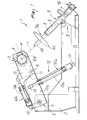
- the reference numeral 1 generally designates a machine for fitting and removing tires of vehicle wheels.
- the machine 1 comprises a frame 2, which supports a structure 3 that can rotate alternately about a substantially horizontal oscillation axis O.
- Grip and rotation means 4 for gripping and turning a vehicle wheel rim about a rotation axis R that is substantially parallel to the oscillation axis O are associated with said structure; the vehicle wheel is not shown in the figures, since it is of a known type.
- an arm 5 is associated with the frame 2 and supports, at one of its ends 5a, two tools 6, which are used to fit and/or remove a tire on and/or from the rim of the wheel.
- Said tools are constituted by a bead breaking tool 6a, such as a conventional disk that can rotate about its own axis, and a hook-like tool 6b of the conventional type.
- the arm 5 can move with respect to the frame 2 and in fact its end 5b that lies opposite the previous end 5a is connected to a slider 7 so that it can rotate about a direction that is parallel to the oscillation axis O.
- the slider 7 is engaged in a guide 8 with which the frame 2 is provided; said guide runs along a direction that is parallel to the oscillation axis O.
- the arm 5 is of the telescopic type, since it is constituted by two tubular elements 9, one of which can be inserted slidingly in the other.
- the coupling of the arm 5 to the frame 2 is such as to allow its movement while keeping its axis substantially perpendicular to the directions traced by the oscillation axis O and rotation axis R.
- the mobility of the arm 5 can be reduced temporarily by way of removable locking means, which are not shown in the figures as they are of a conventional type, so as to allow its placement along a preset working direction L.
- the structure 3 is constituted by a first portion 10a, which is pivoted to the frame 2 so that it can rotate about the oscillation axis O, and by a second portion 10b, which can move with respect to the first portion and supports the supporting means 4.
- the first and second portions 10a and 10b are suitable to cooperate with each other in order to position the means 4 in a working configuration, in which the rotation axis R and the working direction L are mutually incident and the circumferential portion of the rim is arranged in the vicinity of the tools 6.
- the second portion 10b is associated with the first portion 10a so that it can rotate about a tilting axis B that is substantially parallel to the rotation axis R; the free end of the first portion 10a, in particular, is provided with a fork-like body 11, which protrudes longitudinally and at which the second portion 10b is pivoted.
- the machine 1 In order to move the structure 3 with respect to the frame 2, the machine 1 is provided with actuation means 12 of the linear type as described hereinafter.
- first actuation means 12a for actuating the rotation of the first portion 10a about the oscillation axis O are provided; they are advantageously of the type of a first jack 13a with ends that are rotatably associated respectively with the frame 2 and with the first portion 10a at two points 14 that are separate from the oscillation axis O.
- second actuation means 12b for actuating the rotation of the second portion 10b about the tilting axis B, which conveniently comprise a second jack 13b with ends that are respectively associated so that they can rotate with two brackets 15 that protrude upward from the first portion 10a and from the second portion 10b.
- first portion 10a and the second portion 10b are mutually connected so that they can slide along a direction that is substantially perpendicular to the rotation axis R and is illustrated by means of the arrow A in Figure 2.
- first portion 10a and the second portion 10b are constituted, respectively, by a first body tubular body and a second tubular body, which have an elongated shape, are aligned along the direction A, and are mutually coaxial.
- the second body 10b has a portion 16 that is inserted so that it can slide along the direction A within the first body 10a, which acts as a guide.
- actuation means 12 that are of the linear type, which can be actuated on command.
- third actuation means 12c for actuating the sliding of one portion with respect to the other along the direction A.
- said third actuation means are constituted by a third jack 13c, which is aligned with the direction A and in which the ends are associated with the respective portions 10a and 10b.
- the actuation means 12 (12a, 12b, 12c) are shown as being of the fluid-operated (hydraulic or pneumatic) linear type, but alternative embodiments can be used also, in which they are rotary, and/or they are electrically-operated or are actuation means of other suitable type.
- the operation of the present invention is as follows: initially, the wheel rim must be fitted on the means 4 in a manner similar to that of conventional machines.
- the first and second portions 10a and 10b may be moved by acting independently on the respective actuation means 12 until the working configuration is reached.
- the two degrees of freedom given to the structure that supports the wheel further, allow to obtain a tire changing machine that is capable of working in more compact configurations than conventional machines and in which the flexural loads of the cantilevered mechanical elements are particularly modest.
- the wheel supporting structure has a mobility that allows to position the grip means proximate to wheel rims that are resting on the ground, in order to allow to grip them without resorting to external lifting means; likewise, the same advantage can be observed during removal of the wheel from the grip means.
Landscapes
- Engineering & Computer Science (AREA)
- Mechanical Engineering (AREA)
- Vehicle Cleaning, Maintenance, Repair, Refitting, And Outriggers (AREA)
- Tires In General (AREA)
- Forklifts And Lifting Vehicles (AREA)
- Carriers, Traveling Bodies, And Overhead Traveling Cranes (AREA)
Applications Claiming Priority (2)
| Application Number | Priority Date | Filing Date | Title |
|---|---|---|---|
| IT000044A ITMO20040044A1 (it) | 2004-02-27 | 2004-02-27 | Macchina per il montaggio e lo smontaggio di pneumatici di ruote per veicoli |
| ITMO20040044 | 2004-02-27 |
Publications (3)
| Publication Number | Publication Date |
|---|---|
| EP1584496A2 true EP1584496A2 (fr) | 2005-10-12 |
| EP1584496A3 EP1584496A3 (fr) | 2005-11-09 |
| EP1584496B1 EP1584496B1 (fr) | 2006-11-08 |
Family
ID=34897803
Family Applications (1)
| Application Number | Title | Priority Date | Filing Date |
|---|---|---|---|
| EP05101144A Not-in-force EP1584496B1 (fr) | 2004-02-27 | 2005-02-16 | Machine de montage et démontage de pneumatiques sur roues |
Country Status (7)
| Country | Link |
|---|---|
| US (1) | US20050205214A1 (fr) |
| EP (1) | EP1584496B1 (fr) |
| JP (1) | JP4764645B2 (fr) |
| CN (1) | CN1660613A (fr) |
| AT (1) | ATE344736T1 (fr) |
| DE (1) | DE602005000235T2 (fr) |
| IT (1) | ITMO20040044A1 (fr) |
Cited By (3)
| Publication number | Priority date | Publication date | Assignee | Title |
|---|---|---|---|---|
| EP1623850A1 (fr) * | 2004-08-03 | 2006-02-08 | SICAM S.r.l. | Machine de montage de pneumatiques |
| ITPG20130021A1 (it) * | 2013-05-17 | 2014-11-18 | M & B Engineering Srl | Macchina smontagomme per autocarri |
| US11254174B2 (en) | 2018-10-10 | 2022-02-22 | Butler Engineering And Marketing S.P.A. | Machine for mounting and/or removing vehicle wheels, in particular truck wheels |
Families Citing this family (4)
| Publication number | Priority date | Publication date | Assignee | Title |
|---|---|---|---|---|
| ITMO20040044A1 (it) | 2004-02-27 | 2004-05-27 | Sicam Srl | Macchina per il montaggio e lo smontaggio di pneumatici di ruote per veicoli |
| ITMO20060275A1 (it) * | 2006-09-08 | 2008-03-09 | Giuliano Spa | Macchina per il montaggio e lo smontaggio di ruote di veicoli |
| FR3005439B1 (fr) * | 2013-05-07 | 2015-05-15 | Guernet Compresseurs | Dispositif embarque de montage/demontage de pneumatiques de vehicules du type poids lourds |
| CN106004272A (zh) * | 2016-03-21 | 2016-10-12 | 昊龙科技(营口)发展有限公司 | 一种重型车辆轮胎拆装机的举升机构 |
Citations (1)
| Publication number | Priority date | Publication date | Assignee | Title |
|---|---|---|---|---|
| ITMO20040044A1 (it) | 2004-02-27 | 2004-05-27 | Sicam Srl | Macchina per il montaggio e lo smontaggio di pneumatici di ruote per veicoli |
Family Cites Families (11)
| Publication number | Priority date | Publication date | Assignee | Title |
|---|---|---|---|---|
| US3164199A (en) * | 1961-09-26 | 1965-01-05 | Bishman Mfg Company | Tire changer |
| US4031941A (en) * | 1976-02-17 | 1977-06-28 | S. W. Malinski | Concentric contra-rotating bead deflector mechanism for tire mounting apparatus |
| EP0042363B1 (fr) * | 1980-06-12 | 1985-01-23 | Snap-on Equipment Srl a unico socio. | Appareil pour le montage et démontage de pneumatiques |
| IT1243660B (it) * | 1990-10-22 | 1994-06-16 | Corghi Spa | Macchina smontagomme con autrocentrante reclinabile. |
| DK44893D0 (da) * | 1993-04-21 | 1993-04-21 | Hjort Hansen Arne | Apparat til af- og paamontering af hjuldaek, navnlig store daek |
| JP2002528311A (ja) * | 1998-02-20 | 2002-09-03 | エイム オートモウティブ インテグレイテド マニュファクチャリング,インコーポレイテッド | タイヤをリムに組み付けるロボット装置および方法 |
| US6125904A (en) * | 1998-06-01 | 2000-10-03 | Aim Automotive Integrated Manufacturing, Inc. | Robotic apparatus and method for assembling a tire to a rim |
| FR2778872A1 (fr) * | 1998-05-25 | 1999-11-26 | Michelin & Cie | Procede et machine de montage de pneumatiques |
| IT1309353B1 (it) * | 1999-04-02 | 2002-01-22 | Butler Eng & Marketing | Macchina monta-smontagomme per ruote di veicoli industriali. |
| JP2005053281A (ja) * | 2003-08-08 | 2005-03-03 | Onodani Kiko Kk | タイヤ着脱装置 |
| ITMO20040205A1 (it) * | 2004-08-03 | 2004-11-03 | Sicam Srl | 'macchina perfezionata per il motaggio e lo smontaggio di pneumatici di ruote per veicoli'. |
-
2004
- 2004-02-27 IT IT000044A patent/ITMO20040044A1/it unknown
-
2005
- 2005-02-16 AT AT05101144T patent/ATE344736T1/de not_active IP Right Cessation
- 2005-02-16 DE DE602005000235T patent/DE602005000235T2/de active Active
- 2005-02-16 EP EP05101144A patent/EP1584496B1/fr not_active Not-in-force
- 2005-02-17 US US11/059,671 patent/US20050205214A1/en not_active Abandoned
- 2005-02-24 JP JP2005049150A patent/JP4764645B2/ja not_active Expired - Fee Related
- 2005-02-25 CN CN200510052839.0A patent/CN1660613A/zh active Pending
Patent Citations (1)
| Publication number | Priority date | Publication date | Assignee | Title |
|---|---|---|---|---|
| ITMO20040044A1 (it) | 2004-02-27 | 2004-05-27 | Sicam Srl | Macchina per il montaggio e lo smontaggio di pneumatici di ruote per veicoli |
Cited By (7)
| Publication number | Priority date | Publication date | Assignee | Title |
|---|---|---|---|---|
| EP1623850A1 (fr) * | 2004-08-03 | 2006-02-08 | SICAM S.r.l. | Machine de montage de pneumatiques |
| US7188657B2 (en) | 2004-08-03 | 2007-03-13 | Sicam S.R.L. | Machine for fitting and removing vehicle wheel tires |
| ITPG20130021A1 (it) * | 2013-05-17 | 2014-11-18 | M & B Engineering Srl | Macchina smontagomme per autocarri |
| WO2014184645A1 (fr) | 2013-05-17 | 2014-11-20 | M&B Engineering S.R.L. | Machine à changer les pneus pour camions |
| EP2996889B1 (fr) | 2013-05-17 | 2017-02-01 | M&B Engineering S.r.l. | Machine pour le changement des pneus poids lourd |
| US10173482B2 (en) | 2013-05-17 | 2019-01-08 | M&B Engineering S.R.L. | Tyre-changing machine for trucks |
| US11254174B2 (en) | 2018-10-10 | 2022-02-22 | Butler Engineering And Marketing S.P.A. | Machine for mounting and/or removing vehicle wheels, in particular truck wheels |
Also Published As
| Publication number | Publication date |
|---|---|
| JP2005239145A (ja) | 2005-09-08 |
| DE602005000235D1 (de) | 2006-12-21 |
| EP1584496B1 (fr) | 2006-11-08 |
| ATE344736T1 (de) | 2006-11-15 |
| US20050205214A1 (en) | 2005-09-22 |
| ITMO20040044A1 (it) | 2004-05-27 |
| JP4764645B2 (ja) | 2011-09-07 |
| EP1584496A3 (fr) | 2005-11-09 |
| CN1660613A (zh) | 2005-08-31 |
| DE602005000235T2 (de) | 2007-08-23 |
Similar Documents
| Publication | Publication Date | Title |
|---|---|---|
| EP1623850B1 (fr) | Machine de montage de pneumatiques | |
| EP1584496B1 (fr) | Machine de montage et démontage de pneumatiques sur roues | |
| JP4519984B2 (ja) | 工業上の車両ホイール用のタイヤ交換機 | |
| US8291958B2 (en) | Machine for fitting and removing the tires of vehicles | |
| EP1591280B1 (fr) | Broche permettant la fixation d'une jante sur une machine de montage de pneumatique | |
| EP1897709B1 (fr) | Machine de fixation et de retrait de pneumatiques de véhicules | |
| ITMO20080265A1 (it) | Testa operativa per lo smontaggio ed il montaggio di pneumatici di ruote per veicoli | |
| EP2927028B1 (fr) | Machine permettant de monter/retirer un pneumatique | |
| ITMO20100295A1 (it) | Macchina smontagomme | |
| ITRE20080037A1 (it) | "macchina smontagomme e relativo metodo di stallonatura" | |
| EP1201467A2 (fr) | Machine de démontage de pneumatiques | |
| JP5486794B2 (ja) | 車両用ホイールタイヤの取り付け・取り外し装置 | |
| US6192959B1 (en) | Machine for fitting and removing tires | |
| EP1524134A1 (fr) | Appareil briseur de talons pour machine de démontage de pneumatiques | |
| EP2705964B1 (fr) | Appareil de verrouillage de jantes de roue pour véhicules sur des machines d'atelier de réparation ou similaires | |
| JP2000225819A (ja) | 特殊タイヤ取付け・取外し用機械 | |
| EP1479539B1 (fr) | Machine pour le montage et le démontage de pneus et de jantes de roues de véhicules | |
| EP0624486B1 (fr) | Machine pour monter un pneu sur une roue | |
| EP2281699B1 (fr) | Unité de démonte-talons de pneus dans des machines de changement de pneus | |
| EP1717064A1 (fr) | Outil pour le montage/ démontage des pneumatiques | |
| JP5904956B2 (ja) | タイヤ着脱装置 | |
| US20050092442A1 (en) | Tire changing machine implement for fitting and removing tires of vehicle wheels | |
| EP1717065B1 (fr) | Outil pour le montage/ démontage des pneumatiques | |
| WO2023228009A1 (fr) | Dispositif de montage/démontage de pneus | |
| IT201900017099A1 (it) | Testa operativa per un apparato di smontaggio di uno pneumatico |
Legal Events
| Date | Code | Title | Description |
|---|---|---|---|
| PUAI | Public reference made under article 153(3) epc to a published international application that has entered the european phase |
Free format text: ORIGINAL CODE: 0009012 |
|
| PUAL | Search report despatched |
Free format text: ORIGINAL CODE: 0009013 |
|
| AK | Designated contracting states |
Kind code of ref document: A2 Designated state(s): AT BE BG CH CY CZ DE DK EE ES FI FR GB GR HU IE IS IT LI LT LU MC NL PL PT RO SE SI SK TR |
|
| AX | Request for extension of the european patent |
Extension state: AL BA HR LV MK YU |
|
| AK | Designated contracting states |
Kind code of ref document: A3 Designated state(s): AT BE BG CH CY CZ DE DK EE ES FI FR GB GR HU IE IS IT LI LT LU MC NL PL PT RO SE SI SK TR |
|
| AX | Request for extension of the european patent |
Extension state: AL BA HR LV MK YU |
|
| 17P | Request for examination filed |
Effective date: 20060221 |
|
| GRAP | Despatch of communication of intention to grant a patent |
Free format text: ORIGINAL CODE: EPIDOSNIGR1 |
|
| AKX | Designation fees paid |
Designated state(s): AT BE BG CH CY CZ DE DK EE ES FI FR GB GR HU IE IS IT LI LT LU MC NL PL PT RO SE SI SK TR |
|
| GRAS | Grant fee paid |
Free format text: ORIGINAL CODE: EPIDOSNIGR3 |
|
| GRAA | (expected) grant |
Free format text: ORIGINAL CODE: 0009210 |
|
| AK | Designated contracting states |
Kind code of ref document: B1 Designated state(s): AT BE BG CH CY CZ DE DK EE ES FI FR GB GR HU IE IS IT LI LT LU MC NL PL PT RO SE SI SK TR |
|
| PG25 | Lapsed in a contracting state [announced via postgrant information from national office to epo] |
Ref country code: AT Free format text: LAPSE BECAUSE OF FAILURE TO SUBMIT A TRANSLATION OF THE DESCRIPTION OR TO PAY THE FEE WITHIN THE PRESCRIBED TIME-LIMIT Effective date: 20061108 Ref country code: NL Free format text: LAPSE BECAUSE OF FAILURE TO SUBMIT A TRANSLATION OF THE DESCRIPTION OR TO PAY THE FEE WITHIN THE PRESCRIBED TIME-LIMIT Effective date: 20061108 Ref country code: PL Free format text: LAPSE BECAUSE OF FAILURE TO SUBMIT A TRANSLATION OF THE DESCRIPTION OR TO PAY THE FEE WITHIN THE PRESCRIBED TIME-LIMIT Effective date: 20061108 Ref country code: CZ Free format text: LAPSE BECAUSE OF FAILURE TO SUBMIT A TRANSLATION OF THE DESCRIPTION OR TO PAY THE FEE WITHIN THE PRESCRIBED TIME-LIMIT Effective date: 20061108 Ref country code: LI Free format text: LAPSE BECAUSE OF FAILURE TO SUBMIT A TRANSLATION OF THE DESCRIPTION OR TO PAY THE FEE WITHIN THE PRESCRIBED TIME-LIMIT Effective date: 20061108 Ref country code: SI Free format text: LAPSE BECAUSE OF FAILURE TO SUBMIT A TRANSLATION OF THE DESCRIPTION OR TO PAY THE FEE WITHIN THE PRESCRIBED TIME-LIMIT Effective date: 20061108 Ref country code: FI Free format text: LAPSE BECAUSE OF FAILURE TO SUBMIT A TRANSLATION OF THE DESCRIPTION OR TO PAY THE FEE WITHIN THE PRESCRIBED TIME-LIMIT Effective date: 20061108 Ref country code: SK Free format text: LAPSE BECAUSE OF FAILURE TO SUBMIT A TRANSLATION OF THE DESCRIPTION OR TO PAY THE FEE WITHIN THE PRESCRIBED TIME-LIMIT Effective date: 20061108 Ref country code: RO Free format text: LAPSE BECAUSE OF FAILURE TO SUBMIT A TRANSLATION OF THE DESCRIPTION OR TO PAY THE FEE WITHIN THE PRESCRIBED TIME-LIMIT Effective date: 20061108 Ref country code: CH Free format text: LAPSE BECAUSE OF FAILURE TO SUBMIT A TRANSLATION OF THE DESCRIPTION OR TO PAY THE FEE WITHIN THE PRESCRIBED TIME-LIMIT Effective date: 20061108 |
|
| REG | Reference to a national code |
Ref country code: GB Ref legal event code: FG4D |
|
| REG | Reference to a national code |
Ref country code: CH Ref legal event code: EP |
|
| REG | Reference to a national code |
Ref country code: IE Ref legal event code: FG4D |
|
| REF | Corresponds to: |
Ref document number: 602005000235 Country of ref document: DE Date of ref document: 20061221 Kind code of ref document: P |
|
| PG25 | Lapsed in a contracting state [announced via postgrant information from national office to epo] |
Ref country code: BG Free format text: LAPSE BECAUSE OF FAILURE TO SUBMIT A TRANSLATION OF THE DESCRIPTION OR TO PAY THE FEE WITHIN THE PRESCRIBED TIME-LIMIT Effective date: 20070208 Ref country code: DK Free format text: LAPSE BECAUSE OF FAILURE TO SUBMIT A TRANSLATION OF THE DESCRIPTION OR TO PAY THE FEE WITHIN THE PRESCRIBED TIME-LIMIT Effective date: 20070208 Ref country code: SE Free format text: LAPSE BECAUSE OF FAILURE TO SUBMIT A TRANSLATION OF THE DESCRIPTION OR TO PAY THE FEE WITHIN THE PRESCRIBED TIME-LIMIT Effective date: 20070208 |
|
| PG25 | Lapsed in a contracting state [announced via postgrant information from national office to epo] |
Ref country code: ES Free format text: LAPSE BECAUSE OF FAILURE TO SUBMIT A TRANSLATION OF THE DESCRIPTION OR TO PAY THE FEE WITHIN THE PRESCRIBED TIME-LIMIT Effective date: 20070219 |
|
| PG25 | Lapsed in a contracting state [announced via postgrant information from national office to epo] |
Ref country code: MC Free format text: LAPSE BECAUSE OF NON-PAYMENT OF DUE FEES Effective date: 20070228 |
|
| PG25 | Lapsed in a contracting state [announced via postgrant information from national office to epo] |
Ref country code: IS Free format text: LAPSE BECAUSE OF FAILURE TO SUBMIT A TRANSLATION OF THE DESCRIPTION OR TO PAY THE FEE WITHIN THE PRESCRIBED TIME-LIMIT Effective date: 20070308 |
|
| PG25 | Lapsed in a contracting state [announced via postgrant information from national office to epo] |
Ref country code: PT Free format text: LAPSE BECAUSE OF FAILURE TO SUBMIT A TRANSLATION OF THE DESCRIPTION OR TO PAY THE FEE WITHIN THE PRESCRIBED TIME-LIMIT Effective date: 20070409 |
|
| NLV1 | Nl: lapsed or annulled due to failure to fulfill the requirements of art. 29p and 29m of the patents act | ||
| REG | Reference to a national code |
Ref country code: CH Ref legal event code: PL |
|
| ET | Fr: translation filed | ||
| PLBE | No opposition filed within time limit |
Free format text: ORIGINAL CODE: 0009261 |
|
| STAA | Information on the status of an ep patent application or granted ep patent |
Free format text: STATUS: NO OPPOSITION FILED WITHIN TIME LIMIT |
|
| 26N | No opposition filed |
Effective date: 20070809 |
|
| PG25 | Lapsed in a contracting state [announced via postgrant information from national office to epo] |
Ref country code: IE Free format text: LAPSE BECAUSE OF NON-PAYMENT OF DUE FEES Effective date: 20070216 |
|
| PG25 | Lapsed in a contracting state [announced via postgrant information from national office to epo] |
Ref country code: GR Free format text: LAPSE BECAUSE OF FAILURE TO SUBMIT A TRANSLATION OF THE DESCRIPTION OR TO PAY THE FEE WITHIN THE PRESCRIBED TIME-LIMIT Effective date: 20070209 |
|
| PG25 | Lapsed in a contracting state [announced via postgrant information from national office to epo] |
Ref country code: LT Free format text: LAPSE BECAUSE OF FAILURE TO SUBMIT A TRANSLATION OF THE DESCRIPTION OR TO PAY THE FEE WITHIN THE PRESCRIBED TIME-LIMIT Effective date: 20061108 |
|
| PG25 | Lapsed in a contracting state [announced via postgrant information from national office to epo] |
Ref country code: EE Free format text: LAPSE BECAUSE OF FAILURE TO SUBMIT A TRANSLATION OF THE DESCRIPTION OR TO PAY THE FEE WITHIN THE PRESCRIBED TIME-LIMIT Effective date: 20061108 |
|
| PG25 | Lapsed in a contracting state [announced via postgrant information from national office to epo] |
Ref country code: LU Free format text: LAPSE BECAUSE OF NON-PAYMENT OF DUE FEES Effective date: 20070216 Ref country code: CY Free format text: LAPSE BECAUSE OF FAILURE TO SUBMIT A TRANSLATION OF THE DESCRIPTION OR TO PAY THE FEE WITHIN THE PRESCRIBED TIME-LIMIT Effective date: 20061108 |
|
| PG25 | Lapsed in a contracting state [announced via postgrant information from national office to epo] |
Ref country code: HU Free format text: LAPSE BECAUSE OF FAILURE TO SUBMIT A TRANSLATION OF THE DESCRIPTION OR TO PAY THE FEE WITHIN THE PRESCRIBED TIME-LIMIT Effective date: 20070509 |
|
| GBPC | Gb: european patent ceased through non-payment of renewal fee |
Effective date: 20090216 |
|
| PG25 | Lapsed in a contracting state [announced via postgrant information from national office to epo] |
Ref country code: GB Free format text: LAPSE BECAUSE OF NON-PAYMENT OF DUE FEES Effective date: 20090216 |
|
| REG | Reference to a national code |
Ref country code: FR Ref legal event code: CA Effective date: 20111007 |
|
| REG | Reference to a national code |
Ref country code: FR Ref legal event code: PLFP Year of fee payment: 12 |
|
| REG | Reference to a national code |
Ref country code: FR Ref legal event code: PLFP Year of fee payment: 13 |
|
| REG | Reference to a national code |
Ref country code: FR Ref legal event code: PLFP Year of fee payment: 14 |
|
| PGFP | Annual fee paid to national office [announced via postgrant information from national office to epo] |
Ref country code: BE Payment date: 20180221 Year of fee payment: 14 Ref country code: TR Payment date: 20180214 Year of fee payment: 14 |
|
| REG | Reference to a national code |
Ref country code: DE Ref legal event code: R082 Ref document number: 602005000235 Country of ref document: DE Representative=s name: SCHMITT-NILSON SCHRAUD WAIBEL WOHLFROM PATENTA, DE |
|
| REG | Reference to a national code |
Ref country code: BE Ref legal event code: MM Effective date: 20190228 |
|
| PG25 | Lapsed in a contracting state [announced via postgrant information from national office to epo] |
Ref country code: BE Free format text: LAPSE BECAUSE OF NON-PAYMENT OF DUE FEES Effective date: 20190228 |
|
| PGFP | Annual fee paid to national office [announced via postgrant information from national office to epo] |
Ref country code: FR Payment date: 20200219 Year of fee payment: 16 |
|
| PGFP | Annual fee paid to national office [announced via postgrant information from national office to epo] |
Ref country code: IT Payment date: 20210226 Year of fee payment: 17 |
|
| PGFP | Annual fee paid to national office [announced via postgrant information from national office to epo] |
Ref country code: DE Payment date: 20210426 Year of fee payment: 17 |
|
| PG25 | Lapsed in a contracting state [announced via postgrant information from national office to epo] |
Ref country code: FR Free format text: LAPSE BECAUSE OF NON-PAYMENT OF DUE FEES Effective date: 20210228 |
|
| PG25 | Lapsed in a contracting state [announced via postgrant information from national office to epo] |
Ref country code: TR Free format text: LAPSE BECAUSE OF NON-PAYMENT OF DUE FEES Effective date: 20190216 |
|
| REG | Reference to a national code |
Ref country code: DE Ref legal event code: R119 Ref document number: 602005000235 Country of ref document: DE |
|
| PG25 | Lapsed in a contracting state [announced via postgrant information from national office to epo] |
Ref country code: DE Free format text: LAPSE BECAUSE OF NON-PAYMENT OF DUE FEES Effective date: 20220901 |
|
| PG25 | Lapsed in a contracting state [announced via postgrant information from national office to epo] |
Ref country code: IT Free format text: LAPSE BECAUSE OF NON-PAYMENT OF DUE FEES Effective date: 20220216 |