EP1584472A1 - Registervorrichtung mit Strangklemmung - Google Patents
Registervorrichtung mit Strangklemmung Download PDFInfo
- Publication number
- EP1584472A1 EP1584472A1 EP04105353A EP04105353A EP1584472A1 EP 1584472 A1 EP1584472 A1 EP 1584472A1 EP 04105353 A EP04105353 A EP 04105353A EP 04105353 A EP04105353 A EP 04105353A EP 1584472 A1 EP1584472 A1 EP 1584472A1
- Authority
- EP
- European Patent Office
- Prior art keywords
- roller
- strands
- register device
- register
- rollers
- Prior art date
- Legal status (The legal status is an assumption and is not a legal conclusion. Google has not performed a legal analysis and makes no representation as to the accuracy of the status listed.)
- Granted
Links
- 238000003825 pressing Methods 0.000 claims abstract description 3
- 230000003014 reinforcing effect Effects 0.000 claims 1
- 238000011144 upstream manufacturing Methods 0.000 description 5
- 238000005520 cutting process Methods 0.000 description 2
- 210000003746 feather Anatomy 0.000 description 2
- 238000004519 manufacturing process Methods 0.000 description 2
- 238000001514 detection method Methods 0.000 description 1
- 238000004091 panning Methods 0.000 description 1
- 230000000284 resting effect Effects 0.000 description 1
- 238000004904 shortening Methods 0.000 description 1
- 238000003860 storage Methods 0.000 description 1
- 238000010408 sweeping Methods 0.000 description 1
Images
Classifications
-
- B—PERFORMING OPERATIONS; TRANSPORTING
- B41—PRINTING; LINING MACHINES; TYPEWRITERS; STAMPS
- B41F—PRINTING MACHINES OR PRESSES
- B41F33/00—Indicating, counting, warning, control or safety devices
- B41F33/18—Web break detection
-
- B—PERFORMING OPERATIONS; TRANSPORTING
- B41—PRINTING; LINING MACHINES; TYPEWRITERS; STAMPS
- B41P—INDEXING SCHEME RELATING TO PRINTING, LINING MACHINES, TYPEWRITERS, AND TO STAMPS
- B41P2233/00—Arrangements for the operation of printing presses
- B41P2233/20—Safety devices preventing damage
Definitions
- the invention relates to a register device with strand clamping according to the Preamble of claim 1.
- DE 195 09 167 C2 discloses a web catching device in which two rolls by means of Pneumatic cylinders are employed for clamping a web.
- the invention is based on the object, a register device with strand clamping to accomplish.
- a particular advantage of the device is that they in a disturbance of the strand run a Can perform security function against tamper and winder. Namely, if in particular due to a downstream of the gap of the register device detected Collapse of the tension of a strand, the adjusting device is released to the To clamp strands in the gap, so this is the tensile stress of the strands maintained upstream of the gap. The strands become so upstream from the gap lying parts of the press continue to be pulled out correctly until the Machine comes to a halt, and stoppers and winder are above the crevice prevented.
- the first roller linearly displaceable perform, so that the first roller of the actuator for clamping the strands moved linearly and pressed against the second roller.
- the first Roller be provided for clamping the strands pivotally.
- the first roller can be rotated between two hanging pivoting arms be stored.
- the pivot arms can, for example, on a frame of a Registered device comprehensive device pivotally be articulated. In one In such a case, the setting of the first roller against the second roller by a Swiveling the swivel arms causes, with which then the first roller is swung.
- a tensioned spring can be provided as a drive means of the adjusting device.
- the spring may be under tensile or compressive stress. You can choose from one Resting device be kept in the tensioned state. Upon detection of a Voltage drop downstream of the gap of the register device becomes the spring unlatched. She relaxes and pushes the first roller against the second roller.
- this pneumatic actuator switchable, so that the first roller with the help of the same actuator from the second Roller automatically moved away and brought back to its original position can to eliminate strand remnants and feed new strands.
- the actuator is reinforced by a spring, which is a force in the direction which exerts the strands clamping position of the rollers. It may be z. B. order act a spring integrated in the actuator, or it is outside the actuator provided a spring acting parallel to the actuator. In normal operation of the Register device is this spring as the spring described above under train or Compressive stress.
- a spring which is a force in the direction which exerts the strands clamping position of the rollers. It may be z. B. order act a spring integrated in the actuator, or it is outside the actuator provided a spring acting parallel to the actuator. In normal operation of the Register device is this spring as the spring described above under train or Compressive stress.
- the force exerted by the spring in the direction of the clamping position should be something smaller than one of the pneumatic actuator in the opposite Direction exercisable force, so that the force of the pneumatic actuator is sufficient alone, to cancel the clamping of the strands again and no manual intervention on the Register device is necessary for this.
- the position of the first roller in a normal undisturbed operating condition of Register device can be adjusted by a stop on different positions be defined, against which the actuator presses the first roller with a first force.
- the adjustable stop can register errors between the two strands compensate that by adjusting the position of the stop one of the first roller looping strand changes track distance changes.
- the stop is advantageously designed to be displaceable against a restoring force. He can then for the case of the occurrence of a stuffing or winder on one of the two rolls of Dodge register device against the restoring force, so that an additional Hedging against machine damage is given.
- the register device comprises a downstream one Separating device for separating at least one of the strands.
- a downstream one Separating device for separating at least one of the strands.
- stoppers or winders can be with the separator the strands cut through, so that the stuffer or winder supply is interrupted and this can not continue to grow. In this way, will continue Machine damage avoided.
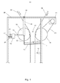
- a register device 01, z. B. a web-fed rotary printing press is shown in Fig. 1 in shown schematic cross-section.
- a roller 04 is rotatable in a frame 08 stored.
- the roller 04 is by means of a drive, in particular by means of a motor 21st driven by a belt 23.
- She is from a strained Strand 06 partially entwined, which consists of a plurality of superimposed Composed partial webs.
- Two pivoting arms 09 are hinged to a mounting point 19 on the frame 08 and pivotable about this. Between the pivot arms 09 is at a the Attachment point 19 respectively opposite end portion of the pivot arms 09 a Roller 02 rotatably mounted. Due to their storage on the pivot arms 09 is the Roller 02 together with the pivot arms 09 to the attachment point 19th pivotable.
- the roller 04 limited with the roller 02 a gap 07.
- the roller 02 is like the roller 04 partially from a train 03 having a tensile stress entwined, consisting of a plurality of superimposed sub strands composed. Both the strand 03 and the strand 06 pass through the Gap 07, which is wide enough to be between the strands 03; 06 to allow a game.
- a boom 22 is provided in each case. At these arms 22 each engages a hinged to the frame 08 pneumatic actuator 11.
- the actuators 11 are pneumatic cylinders 11 which are extended in the normal operation of the register device 01 shown in FIG. 1 and press the pivot arms 09 and thus the roller 02 away from the roller 04 via the arms 22.
- springs 12 which is stretched between the arms 22 and the frame 08.
- the springs 12 are under tension. They act with respect to the force exerted by the actuators 11 on the boom 22 opposite force on the second boom 22, but their spring force is weaker than the force exerted by the actuators 11 force, so that there is no pivoting of the roller 02 on the Roller 04 comes too.
- the pivot arms 09 are pressed in spite of the spring forces by the springs 12 of the roller 04 against a spindle 13 as a stop 13.
- the spindle 13 is rotatable within a thread 16 passing through a thread.
- the carriage 16 is guided on mounted on the frame 08 rails 24.
- a arranged between the carriage 16 and the frame 08 strong pressure-loaded spring 17 keeps the carriage 16 pressed against a stop, not shown.
- the spindle 13 is manually displaceable by means of a handwheel 14 in the thread of the carriage 16.
- a separating device 18 in the form of a cutting blade 18 is provided downstream of the two rollers 02; 04.
- the adjusting device 11, 12 consists z. B. from a pneumatic actuator 11 and a Spring 12th
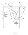
- the strands 03; 06 run in the direction indicated by the arrows through the gap 07, wherein the rollers 02; 04 in the directions also indicated by arrows rotate. It may happen that the strands 03; 06 before entering the gap 07 a Have register errors. Such a register error can be compensated by that the spindle 13 is rotated with the handwheel 14, whereby they are within the Thread in carriage 16 moves forward or backward. Since the swivel arm 09 from the actuator 11 is pressed against the spindle 13, causes a movement of the spindle 13 a corresponding pivotal movement of the pivot arm 09 and the roller 02 on the Roller 04 to and from the roller 04 away.
- the actuator 11 is a double acting actuator 11. This is switched by the compressed gas source of a under normal operating conditions pressurized chamber of the actuator 11th is disconnected and connected to its normally depressurized chamber while at the same time the previously pressurized chamber connected to the low pressure side becomes.
- the actuator 11 contributes to the force acting on the roller 02 force to close of the gap 07 at.
- the strands 03; 06 are between the rollers 02; 04 sandwiched, wherein the switched actuator 11 and the spring 12 for a necessary clamping force by pressing the roller 02 against the roller 04. Since the roller 04 from the engine 21 is driven, builds up a new tension in strand 06 immediately.
- rollers 02, 04 comes to a winder, in which one of the strands 03; 06 around one of the rollers 02; 04 winds and thereby increases its diameter. Sweeping Machine damage due to such a winder is due to the on the rails 24 slidable embodiment of the carriage 16 against the exerted by the spring 17 Restoring force prevented. This allows the carriage 16 with the spindle 13 against the Restoring force by the spring 17, the pressure forces occurring in a winder dodge, so that they are compensated.
- the described register device 01 can be implemented in various ways be modified without departing from the spirit.
- the roller 04 driven by the motor 21.
- the roller 02 a corresponding drive to provide or both rollers 02; 04 by the same motor 21 to drive.
- the roller 02 is shown pivotally.
- the roller 02 be provided linearly displaceable. For example, this can be done on rails slidable bearings of the roller 02 can be achieved.
- the roller 04 is designed to be movable, so that too it can either be pivoted or moved linearly.
- the register device 01 can be inserted between a cross-cutting device of a Querfalzapparates and an upstream L jossfalztrichter be arranged.
- the register means additionally or alternatively between a Leksfalztrichter and an upstream printing unit and / or dryer and / or a especially to arrange last turning bar.
- the center distance of the two rollers to each other changed.
- z. B the position of printed images of different Lanes / strands set to each other.
- strand may be a single or multiple superposed webs be understood.
Landscapes
- Advance Control (AREA)
- Tension Adjustment In Filamentary Materials (AREA)
- Controlling Rewinding, Feeding, Winding, Or Abnormalities Of Webs (AREA)
- Replacement Of Web Rolls (AREA)
- Treatment Of Fiber Materials (AREA)
Abstract
Description
- Fig. 1
- einen schematischen Querschnitt durch eine Registervorrichtung im normalen Betrieb;
- Fig. 2
- die Registervorrichtung aus Fig. 1 mit eingeklemmten Strängen.
Von den Stellgliedern 11 werden die Schwenkarme 09 trotz der Federkräfte durch die Federn 12 von der Walze 04 weg gegen eine Spindel 13 als Anschlag 13 gedrückt. Die Spindel 13 ist innerhalb eines einen Schlitten 16 durchlaufenden Gewindes drehbar. Der Schlitten 16 ist auf am Gestell 08 befestigten Schienen 24 geführt. Eine zwischen dem Schlitten 16 und dem Gestell 08 angeordnete kräftige druckbelastete Feder 17 hält den Schlitten 16 gegen einen nicht dargestellten Anschlag gedrückt. Die Spindel 13 ist mittels eines Handrades 14 manuell im Gewinde des Schlittens 16 verschiebbar. Schließlich ist stromabwärts der beiden Walzen 02; 04 eine Trennvorrichtung 18 in Form eines Abschlagmessers 18 vorgesehen.
- 01
- Registervorrichtung
- 02
- Walze, erste
- 03
- Strang, erster
- 04
- Walze, zweite
- 05
- -
- 06
- Strang, zweiter
- 07
- Spalt
- 08
- Gestell
- 09
- Schwenkarm
- 10
- -
- 11
- Stellglied, Zylinder, pneumatische
- 12
- Feder
- 13
- Anschlag, Spindel
- 14
- Handrad
- 15
- -
- 16
- Schlitten
- 17
- Feder
- 18
- Trennvorrichtung, Abschlagmesser
- 19
- Befestigungs-/Schwenkpunkt
- 20
- -
- 21
- Motor
- 22
- Ausleger
- 23
- Riemen
- 24
- Schiene
Claims (19)
- Registervorrichtung (01) mit einer drehbaren ersten Walze (02), die von einem unter einer Zugspannung stehenden ersten Strang (03) wenigstens teilweise umschlungen ist, und einer drehbaren zweiten Walze (04), die von einem unter einer Zugspannung stehenden zweiten Strang (06) wenigstens teilweise umschlungen ist, wobei die Walzen (02; 04) in einer ersten Betriebsart einen Spalt (07) begrenzen, den die Stränge (03; 06) durchlaufen, wobei wenigstens die erste Walze (02) zum Registern der Stränge (03; 06) relativ zur zweiten Walze (04) bewegbar ist, dadurch gekennzeichnet, dass eine Stelleinrichtung (11, 12) zum Andrücken der ersten Walze (02) in einer zweiten Betriebsart gegen die zweite Walze (04) angeordnet ist, so dass die Stränge (03; 06) zwischen beiden Walzen (02; 04) eingeklemmt sind.
- Registervorrichtung (01) nach Anspruch 1, dadurch gekennzeichnet, dass ein Sensor zur Ermittlung einer Störung eines Stranglaufes angeordnet ist.
- Registervorrichtung (01) nach Anspruch 2, dadurch gekennzeichnet, dass die Stelleinrichtung (11, 12) mit dem Sensor gekoppelt ist, um die erste Walze (02) gegen die zweite Walze (04) zu drücken, wenn der Sensor eine Störung des Stranglaufes wenigstens eines der Stränge (06; 07) erfasst.
- Registervorrichtung (01) nach Anspruch 2, dadurch gekennzeichnet, dass die Stelleinrichtung (11, 12) mit dem stromabwärts vom Spalt (07) angeordneten Sensor gekoppelt ist, um die erste Walze (02) gegen die zweite Walze (04) zu drücken, wenn der Sensor einen Zusammenbruch der Zugspannung wenigstens eines der Stränge (06; 07) erfasst.
- Registervorrichtung (01) nach Anspruch 1, dadurch gekennzeichnet, dass eine erste Stelleinrichtung (11, 12) zum Einstellen des Registers der beiden Stränge und eine zweite Stelleinrichtung (11, 12) zum Anstellen der beiden Walzen (02, 04) angeordnet sind.
- Registervorrichtung (01) nach Anspruch 1, dadurch gekennzeichnet, dass die Registervorrichtung in einer Rollenrotationsdruckmaschine angeordnet ist.
- Registervorrichtung (01) nach Anspruch 1, 3 oder 4, dadurch gekennzeichnet, dass die erste Walze (02) zum Klemmen der Stränge (03; 06) linear verschiebbar ist.
- Registervorrichtung (01) nach Anspruch 1, 3 oder 4 dadurch gekennzeichnet, dass die erste Walze (02) zum Klemmen der Stränge (03; 06) schwenkbar ist.
- Registervorrichtung (01) nach einem der vorhergehenden Ansprüche, dadurch gekennzeichnet, dass die Stelleinrichtung (11, 12) eine gespannte Feder (12) umfasst.
- Registervorrichtung (01) nach einem der Ansprüche 1, 3, 4, 7 oder 8, dadurch gekennzeichnet, dass die Stelleinrichtung (11, 12) ein pneumatisches Stellglied (11) umfasst.
- Registervorrichtung (01) nach Anspruch 10, dadurch gekennzeichnet, dass das Stellglied (11) durch eine Feder (12) verstärkt ist.
- Registervorrichtung (01) nach Anspruch 11, dadurch gekennzeichnet, dass eine von der verstärkenden Feder (12) in Richtung einer die Stränge (06; 07) klemmenden Stellung der ersten Walze (02) ausgeübte Kraft kleiner ist als eine mit dem pneumatischen Stellglied (11) in der entgegengesetzten Richtung ausübbare Kraft.
- Registervorrichtung (01) nach Anspruch 10, 11 oder 12, dadurch gekennzeichnet, dass sie einen Anschlag (13) umfasst, gegen den die Stelleinrichtung (11, 12), solange die Zugspannung stromabwärts des Spalts (07) vorhanden ist, die erste Walze (02) mit einer ersten Kraft drückt.
- Registervorrichtung (01) nach Anspruch 13, dadurch gekennzeichnet, dass der Anschlag (13) gegen eine Rückstellkraft verschiebbar ist, die größer ist als die erste Kraft.
- Registervorrichtung (01) nach einem der vorhergehenden Ansprüche, dadurch gekennzeichnet, dass Registervorrichtung (01) stromabwärts vom Spalt (07) eine Trennvorrichtung (18) zum Trennen wenigstens eines der Stränge (03; 06) umfasst.
- Registervorrichtung (01) nach Anspruch 1, dadurch gekennzeichnet, dass ein Antrieb (21, 23) für wenigstens eine der beiden Walzen (02; 04) angeordnet ist.
- Registervorrichtung (01) nach Anspruch 1, dadurch gekennzeichnet, dass in einer ersten Betriebsart ein Achsabstand der beiden Walzen (02; 04) in Abhängigkeit eines Registers der beiden Stränge (03, 06) eingestellt ist.
- Registervorrichtung (01) nach Anspruch 1, dadurch gekennzeichnet, dass ein Achsabstand der beiden Walzen in Abhängigkeit der Position der Druckbilder der beiden Stränge zueinander eingestellt ist.
- Registervorrichtung (01) nach Anspruch 2, dadurch gekennzeichnet, dass der Sensor eine Zugspannung ermittelnd angeordnet ist.
Applications Claiming Priority (2)
| Application Number | Priority Date | Filing Date | Title |
|---|---|---|---|
| DE102004016672A DE102004016672B3 (de) | 2004-04-05 | 2004-04-05 | Registervorrichtung mit Strangklemmung |
| DE102004016672 | 2004-04-05 |
Publications (2)
| Publication Number | Publication Date |
|---|---|
| EP1584472A1 true EP1584472A1 (de) | 2005-10-12 |
| EP1584472B1 EP1584472B1 (de) | 2009-02-18 |
Family
ID=34895479
Family Applications (1)
| Application Number | Title | Priority Date | Filing Date |
|---|---|---|---|
| EP04105353A Expired - Lifetime EP1584472B1 (de) | 2004-04-05 | 2004-10-28 | Registervorrichtung mit Strangklemmung |
Country Status (3)
| Country | Link |
|---|---|
| EP (1) | EP1584472B1 (de) |
| AT (1) | ATE423005T1 (de) |
| DE (2) | DE102004016672B3 (de) |
Citations (3)
| Publication number | Priority date | Publication date | Assignee | Title |
|---|---|---|---|---|
| DE4201481A1 (de) * | 1992-01-21 | 1993-07-22 | Heidelberger Druckmasch Ag | Einrichtung zur handhabung von materialbahnen in verarbeitungsmaschinen |
| DE19509167C2 (de) | 1995-03-14 | 1997-04-03 | Koenig & Bauer Albert Ag | Bahnfangvorrichtung |
| DE10222363A1 (de) * | 2002-05-21 | 2003-12-11 | Roland Man Druckmasch | Rückhaltevorrichtung für eine in einer Rollenrotationsdruckmaschine laufenden Bedruckstoffbahn |
-
2004
- 2004-04-05 DE DE102004016672A patent/DE102004016672B3/de not_active Expired - Fee Related
- 2004-10-28 EP EP04105353A patent/EP1584472B1/de not_active Expired - Lifetime
- 2004-10-28 AT AT04105353T patent/ATE423005T1/de not_active IP Right Cessation
- 2004-10-28 DE DE502004009009T patent/DE502004009009D1/de not_active Expired - Lifetime
Patent Citations (3)
| Publication number | Priority date | Publication date | Assignee | Title |
|---|---|---|---|---|
| DE4201481A1 (de) * | 1992-01-21 | 1993-07-22 | Heidelberger Druckmasch Ag | Einrichtung zur handhabung von materialbahnen in verarbeitungsmaschinen |
| DE19509167C2 (de) | 1995-03-14 | 1997-04-03 | Koenig & Bauer Albert Ag | Bahnfangvorrichtung |
| DE10222363A1 (de) * | 2002-05-21 | 2003-12-11 | Roland Man Druckmasch | Rückhaltevorrichtung für eine in einer Rollenrotationsdruckmaschine laufenden Bedruckstoffbahn |
Also Published As
| Publication number | Publication date |
|---|---|
| DE502004009009D1 (de) | 2009-04-02 |
| DE102004016672B3 (de) | 2005-10-27 |
| ATE423005T1 (de) | 2009-03-15 |
| EP1584472B1 (de) | 2009-02-18 |
Similar Documents
| Publication | Publication Date | Title |
|---|---|---|
| AT393260B (de) | Vorrichtung zum aufwickeln einer endlosen bahn, z. b. papier- oder kartonbahn, auf wickelwalzen | |
| EP0575787A1 (de) | Falzapparat zum Herstellen von gefalteten Exemplaren aus einer bedruckten Papierbahn | |
| CH693985A5 (fr) | Vorrichtung und Verfahren zum Schneiden einer Materialbahn, insbesondere in einer Rotationsdruckmaschine. | |
| DE4340858A1 (de) | Zylinder | |
| DE19845842B4 (de) | Verfahren und Vorrichtung zur Herstellung einer Garnwicklung auf einer Spule | |
| EP0540896B1 (de) | Wickelmaschine zum Aufwickeln einer Warenbahn, insbesondere einer Papierbahn | |
| EP1584472B1 (de) | Registervorrichtung mit Strangklemmung | |
| DE29610199U1 (de) | Querschneidevorrichtung für Wickelmaschinen | |
| EP0896942A2 (de) | Vorrichtung zur Aufteilung von Exemplarströmen hinter einem Falzapparat | |
| DE4302345A1 (de) | Rollenschneidmaschine zum Aufwickeln von vorzugsweise schmalen Materialbahnen, insbesondere aus Kunststoff, Papier oder dergleichen in Einzelwickelstationen | |
| DE3929227A1 (de) | Papierbahntrenn- und -halteeinrichtung | |
| DE19754106A1 (de) | Vorrichtung und Verfahren zum Einziehen einer Bedruckstoffbahn | |
| EP0734988B1 (de) | Verfahren und Einrichtung zum Bewegen von Punkturnadeln | |
| DE3428512A1 (de) | Vorrichtung an einem falzklappenzylinder zur uebernahme von falzprodukten | |
| EP1938977B1 (de) | Vorrichtung und ein Verfahren zum Einziehen mindestens einer Materialbahn bzw. mindestens eines Bahnstrangs in einen Falzapparat | |
| EP1184314A2 (de) | Vorrichtung zum Führen von Signaturen, insbesondere im Bereich eines Auslauf-Zwickels einer Schneidzylinderanordnung in einem Falzapparat einer Rotationsdruckmaschine | |
| DE102005045040B4 (de) | Vorrichtung zum Kappen und/oder Zuführen eines Stranges in eine Weiterverarbeitungsstufe | |
| DE102004053536A1 (de) | Verfahren und Vorrichtung zum Kappen und/oder Zuführen eines Stranges in eine Weiterverarbeitungsstufe sowie Strangverarbeitungssystem | |
| EP1732833B1 (de) | Verfahren und vorrichtungen zum kappen und/oder zuführen eines stranges in eine weiterverarbeitungsstufe | |
| DE10058437B4 (de) | Vorrichtungen zum Verbinden zweier Materialbahnen | |
| DE202004000600U1 (de) | Vorrichtung zum Überführen einer Materialbahn | |
| DE19518430C2 (de) | Verfahren zum Bewegen von Punkturnadeln | |
| DE10229315C1 (de) | Vorrichtung zur Fixierung einer beweglichen Materialbahn | |
| DE19754151A9 (de) | Einrichtung zur Verbesserung der Falzgenauigkeit im Falzapparat | |
| DE9112927U1 (de) | Wickelmaschine zum Aufwickeln einer Warenbahn, insbesondere einer Papierbahn |
Legal Events
| Date | Code | Title | Description |
|---|---|---|---|
| PUAI | Public reference made under article 153(3) epc to a published international application that has entered the european phase |
Free format text: ORIGINAL CODE: 0009012 |
|
| AK | Designated contracting states |
Kind code of ref document: A1 Designated state(s): AT BE BG CH CY CZ DE DK EE ES FI FR GB GR HU IE IT LI LU MC NL PL PT RO SE SI SK TR |
|
| AX | Request for extension of the european patent |
Extension state: AL HR LT LV MK |
|
| 17P | Request for examination filed |
Effective date: 20050906 |
|
| AKX | Designation fees paid |
Designated state(s): AT BE BG CH CY CZ DE DK EE ES FI FR GB GR HU IE IT LI LU MC NL PL PT RO SE SI SK TR |
|
| GRAP | Despatch of communication of intention to grant a patent |
Free format text: ORIGINAL CODE: EPIDOSNIGR1 |
|
| GRAS | Grant fee paid |
Free format text: ORIGINAL CODE: EPIDOSNIGR3 |
|
| GRAA | (expected) grant |
Free format text: ORIGINAL CODE: 0009210 |
|
| AK | Designated contracting states |
Kind code of ref document: B1 Designated state(s): AT BE BG CH CY CZ DE DK EE ES FI FR GB GR HU IE IT LI LU MC NL PL PT RO SE SI SK TR |
|
| REG | Reference to a national code |
Ref country code: GB Ref legal event code: FG4D Free format text: NOT ENGLISH |
|
| REG | Reference to a national code |
Ref country code: CH Ref legal event code: EP |
|
| REG | Reference to a national code |
Ref country code: IE Ref legal event code: FG4D Free format text: LANGUAGE OF EP DOCUMENT: GERMAN |
|
| REF | Corresponds to: |
Ref document number: 502004009009 Country of ref document: DE Date of ref document: 20090402 Kind code of ref document: P |
|
| PG25 | Lapsed in a contracting state [announced via postgrant information from national office to epo] |
Ref country code: SI Free format text: LAPSE BECAUSE OF FAILURE TO SUBMIT A TRANSLATION OF THE DESCRIPTION OR TO PAY THE FEE WITHIN THE PRESCRIBED TIME-LIMIT Effective date: 20090218 Ref country code: NL Free format text: LAPSE BECAUSE OF FAILURE TO SUBMIT A TRANSLATION OF THE DESCRIPTION OR TO PAY THE FEE WITHIN THE PRESCRIBED TIME-LIMIT Effective date: 20090218 Ref country code: FI Free format text: LAPSE BECAUSE OF FAILURE TO SUBMIT A TRANSLATION OF THE DESCRIPTION OR TO PAY THE FEE WITHIN THE PRESCRIBED TIME-LIMIT Effective date: 20090218 Ref country code: ES Free format text: LAPSE BECAUSE OF FAILURE TO SUBMIT A TRANSLATION OF THE DESCRIPTION OR TO PAY THE FEE WITHIN THE PRESCRIBED TIME-LIMIT Effective date: 20090529 |
|
| NLV1 | Nl: lapsed or annulled due to failure to fulfill the requirements of art. 29p and 29m of the patents act | ||
| PG25 | Lapsed in a contracting state [announced via postgrant information from national office to epo] |
Ref country code: SE Free format text: LAPSE BECAUSE OF FAILURE TO SUBMIT A TRANSLATION OF THE DESCRIPTION OR TO PAY THE FEE WITHIN THE PRESCRIBED TIME-LIMIT Effective date: 20090518 Ref country code: PL Free format text: LAPSE BECAUSE OF FAILURE TO SUBMIT A TRANSLATION OF THE DESCRIPTION OR TO PAY THE FEE WITHIN THE PRESCRIBED TIME-LIMIT Effective date: 20090218 |
|
| REG | Reference to a national code |
Ref country code: IE Ref legal event code: FD4D |
|
| PG25 | Lapsed in a contracting state [announced via postgrant information from national office to epo] |
Ref country code: CZ Free format text: LAPSE BECAUSE OF FAILURE TO SUBMIT A TRANSLATION OF THE DESCRIPTION OR TO PAY THE FEE WITHIN THE PRESCRIBED TIME-LIMIT Effective date: 20090218 Ref country code: DK Free format text: LAPSE BECAUSE OF FAILURE TO SUBMIT A TRANSLATION OF THE DESCRIPTION OR TO PAY THE FEE WITHIN THE PRESCRIBED TIME-LIMIT Effective date: 20090218 Ref country code: EE Free format text: LAPSE BECAUSE OF FAILURE TO SUBMIT A TRANSLATION OF THE DESCRIPTION OR TO PAY THE FEE WITHIN THE PRESCRIBED TIME-LIMIT Effective date: 20090218 Ref country code: IE Free format text: LAPSE BECAUSE OF FAILURE TO SUBMIT A TRANSLATION OF THE DESCRIPTION OR TO PAY THE FEE WITHIN THE PRESCRIBED TIME-LIMIT Effective date: 20090218 Ref country code: PT Free format text: LAPSE BECAUSE OF FAILURE TO SUBMIT A TRANSLATION OF THE DESCRIPTION OR TO PAY THE FEE WITHIN THE PRESCRIBED TIME-LIMIT Effective date: 20090727 |
|
| PG25 | Lapsed in a contracting state [announced via postgrant information from national office to epo] |
Ref country code: RO Free format text: LAPSE BECAUSE OF FAILURE TO SUBMIT A TRANSLATION OF THE DESCRIPTION OR TO PAY THE FEE WITHIN THE PRESCRIBED TIME-LIMIT Effective date: 20090218 Ref country code: SK Free format text: LAPSE BECAUSE OF FAILURE TO SUBMIT A TRANSLATION OF THE DESCRIPTION OR TO PAY THE FEE WITHIN THE PRESCRIBED TIME-LIMIT Effective date: 20090218 |
|
| PLBE | No opposition filed within time limit |
Free format text: ORIGINAL CODE: 0009261 |
|
| STAA | Information on the status of an ep patent application or granted ep patent |
Free format text: STATUS: NO OPPOSITION FILED WITHIN TIME LIMIT |
|
| 26N | No opposition filed |
Effective date: 20091119 |
|
| PG25 | Lapsed in a contracting state [announced via postgrant information from national office to epo] |
Ref country code: BG Free format text: LAPSE BECAUSE OF FAILURE TO SUBMIT A TRANSLATION OF THE DESCRIPTION OR TO PAY THE FEE WITHIN THE PRESCRIBED TIME-LIMIT Effective date: 20090518 |
|
| BERE | Be: lapsed |
Owner name: KOENIG & BAUER A.G. Effective date: 20091031 |
|
| PG25 | Lapsed in a contracting state [announced via postgrant information from national office to epo] |
Ref country code: MC Free format text: LAPSE BECAUSE OF NON-PAYMENT OF DUE FEES Effective date: 20091031 |
|
| PG25 | Lapsed in a contracting state [announced via postgrant information from national office to epo] |
Ref country code: BE Free format text: LAPSE BECAUSE OF NON-PAYMENT OF DUE FEES Effective date: 20091031 Ref country code: GR Free format text: LAPSE BECAUSE OF FAILURE TO SUBMIT A TRANSLATION OF THE DESCRIPTION OR TO PAY THE FEE WITHIN THE PRESCRIBED TIME-LIMIT Effective date: 20090519 |
|
| PG25 | Lapsed in a contracting state [announced via postgrant information from national office to epo] |
Ref country code: AT Free format text: LAPSE BECAUSE OF NON-PAYMENT OF DUE FEES Effective date: 20091028 |
|
| PG25 | Lapsed in a contracting state [announced via postgrant information from national office to epo] |
Ref country code: IT Free format text: LAPSE BECAUSE OF FAILURE TO SUBMIT A TRANSLATION OF THE DESCRIPTION OR TO PAY THE FEE WITHIN THE PRESCRIBED TIME-LIMIT Effective date: 20090218 |
|
| PG25 | Lapsed in a contracting state [announced via postgrant information from national office to epo] |
Ref country code: LU Free format text: LAPSE BECAUSE OF NON-PAYMENT OF DUE FEES Effective date: 20091028 |
|
| PG25 | Lapsed in a contracting state [announced via postgrant information from national office to epo] |
Ref country code: HU Free format text: LAPSE BECAUSE OF FAILURE TO SUBMIT A TRANSLATION OF THE DESCRIPTION OR TO PAY THE FEE WITHIN THE PRESCRIBED TIME-LIMIT Effective date: 20090819 |
|
| PG25 | Lapsed in a contracting state [announced via postgrant information from national office to epo] |
Ref country code: TR Free format text: LAPSE BECAUSE OF FAILURE TO SUBMIT A TRANSLATION OF THE DESCRIPTION OR TO PAY THE FEE WITHIN THE PRESCRIBED TIME-LIMIT Effective date: 20090218 |
|
| PG25 | Lapsed in a contracting state [announced via postgrant information from national office to epo] |
Ref country code: CY Free format text: LAPSE BECAUSE OF FAILURE TO SUBMIT A TRANSLATION OF THE DESCRIPTION OR TO PAY THE FEE WITHIN THE PRESCRIBED TIME-LIMIT Effective date: 20090218 |
|
| PGFP | Annual fee paid to national office [announced via postgrant information from national office to epo] |
Ref country code: FR Payment date: 20121113 Year of fee payment: 9 Ref country code: DE Payment date: 20121207 Year of fee payment: 9 Ref country code: CH Payment date: 20121025 Year of fee payment: 9 |
|
| PGFP | Annual fee paid to national office [announced via postgrant information from national office to epo] |
Ref country code: GB Payment date: 20121024 Year of fee payment: 9 |
|
| REG | Reference to a national code |
Ref country code: CH Ref legal event code: PL |
|
| GBPC | Gb: european patent ceased through non-payment of renewal fee |
Effective date: 20131028 |
|
| REG | Reference to a national code |
Ref country code: DE Ref legal event code: R119 Ref document number: 502004009009 Country of ref document: DE Effective date: 20140501 |
|
| PG25 | Lapsed in a contracting state [announced via postgrant information from national office to epo] |
Ref country code: LI Free format text: LAPSE BECAUSE OF NON-PAYMENT OF DUE FEES Effective date: 20131031 Ref country code: GB Free format text: LAPSE BECAUSE OF NON-PAYMENT OF DUE FEES Effective date: 20131028 Ref country code: CH Free format text: LAPSE BECAUSE OF NON-PAYMENT OF DUE FEES Effective date: 20131031 |
|
| REG | Reference to a national code |
Ref country code: FR Ref legal event code: ST Effective date: 20140630 |
|
| PG25 | Lapsed in a contracting state [announced via postgrant information from national office to epo] |
Ref country code: DE Free format text: LAPSE BECAUSE OF NON-PAYMENT OF DUE FEES Effective date: 20140501 Ref country code: FR Free format text: LAPSE BECAUSE OF NON-PAYMENT OF DUE FEES Effective date: 20131031 |