EP1584427A1 - Transportwalze und Querschneidvorrichtung für Materialbahnen - Google Patents
Transportwalze und Querschneidvorrichtung für Materialbahnen Download PDFInfo
- Publication number
- EP1584427A1 EP1584427A1 EP05006155A EP05006155A EP1584427A1 EP 1584427 A1 EP1584427 A1 EP 1584427A1 EP 05006155 A EP05006155 A EP 05006155A EP 05006155 A EP05006155 A EP 05006155A EP 1584427 A1 EP1584427 A1 EP 1584427A1
- Authority
- EP
- European Patent Office
- Prior art keywords
- transport roller
- roller according
- knife
- groove
- drive
- Prior art date
- Legal status (The legal status is an assumption and is not a legal conclusion. Google has not performed a legal analysis and makes no representation as to the accuracy of the status listed.)
- Granted
Links
Images


Classifications
-
- B—PERFORMING OPERATIONS; TRANSPORTING
- B26—HAND CUTTING TOOLS; CUTTING; SEVERING
- B26D—CUTTING; DETAILS COMMON TO MACHINES FOR PERFORATING, PUNCHING, CUTTING-OUT, STAMPING-OUT OR SEVERING
- B26D1/00—Cutting through work characterised by the nature or movement of the cutting member or particular materials not otherwise provided for; Apparatus or machines therefor; Cutting members therefor
- B26D1/01—Cutting through work characterised by the nature or movement of the cutting member or particular materials not otherwise provided for; Apparatus or machines therefor; Cutting members therefor involving a cutting member which does not travel with the work
- B26D1/04—Cutting through work characterised by the nature or movement of the cutting member or particular materials not otherwise provided for; Apparatus or machines therefor; Cutting members therefor involving a cutting member which does not travel with the work having a linearly-movable cutting member
- B26D1/045—Cutting through work characterised by the nature or movement of the cutting member or particular materials not otherwise provided for; Apparatus or machines therefor; Cutting members therefor involving a cutting member which does not travel with the work having a linearly-movable cutting member for thin material, e.g. for sheets, strips or the like
-
- B—PERFORMING OPERATIONS; TRANSPORTING
- B26—HAND CUTTING TOOLS; CUTTING; SEVERING
- B26D—CUTTING; DETAILS COMMON TO MACHINES FOR PERFORATING, PUNCHING, CUTTING-OUT, STAMPING-OUT OR SEVERING
- B26D1/00—Cutting through work characterised by the nature or movement of the cutting member or particular materials not otherwise provided for; Apparatus or machines therefor; Cutting members therefor
- B26D1/01—Cutting through work characterised by the nature or movement of the cutting member or particular materials not otherwise provided for; Apparatus or machines therefor; Cutting members therefor involving a cutting member which does not travel with the work
- B26D1/04—Cutting through work characterised by the nature or movement of the cutting member or particular materials not otherwise provided for; Apparatus or machines therefor; Cutting members therefor involving a cutting member which does not travel with the work having a linearly-movable cutting member
- B26D1/06—Cutting through work characterised by the nature or movement of the cutting member or particular materials not otherwise provided for; Apparatus or machines therefor; Cutting members therefor involving a cutting member which does not travel with the work having a linearly-movable cutting member wherein the cutting member reciprocates
- B26D1/10—Cutting through work characterised by the nature or movement of the cutting member or particular materials not otherwise provided for; Apparatus or machines therefor; Cutting members therefor involving a cutting member which does not travel with the work having a linearly-movable cutting member wherein the cutting member reciprocates in, or substantially in, a direction parallel to the cutting edge
- B26D1/105—Cutting through work characterised by the nature or movement of the cutting member or particular materials not otherwise provided for; Apparatus or machines therefor; Cutting members therefor involving a cutting member which does not travel with the work having a linearly-movable cutting member wherein the cutting member reciprocates in, or substantially in, a direction parallel to the cutting edge for thin material, e.g. for sheets, strips or the like
-
- B—PERFORMING OPERATIONS; TRANSPORTING
- B65—CONVEYING; PACKING; STORING; HANDLING THIN OR FILAMENTARY MATERIAL
- B65H—HANDLING THIN OR FILAMENTARY MATERIAL, e.g. SHEETS, WEBS, CABLES
- B65H35/00—Delivering articles from cutting or line-perforating machines; Article or web delivery apparatus incorporating cutting or line-perforating devices, e.g. adhesive tape dispensers
- B65H35/0006—Article or web delivery apparatus incorporating cutting or line-perforating devices
- B65H35/0073—Details
- B65H35/008—Arrangements or adaptations of cutting devices
- B65H35/0086—Arrangements or adaptations of cutting devices using movable cutting elements
-
- B—PERFORMING OPERATIONS; TRANSPORTING
- B65—CONVEYING; PACKING; STORING; HANDLING THIN OR FILAMENTARY MATERIAL
- B65H—HANDLING THIN OR FILAMENTARY MATERIAL, e.g. SHEETS, WEBS, CABLES
- B65H35/00—Delivering articles from cutting or line-perforating machines; Article or web delivery apparatus incorporating cutting or line-perforating devices, e.g. adhesive tape dispensers
- B65H35/04—Delivering articles from cutting or line-perforating machines; Article or web delivery apparatus incorporating cutting or line-perforating devices, e.g. adhesive tape dispensers from or with transverse cutters or perforators
-
- B—PERFORMING OPERATIONS; TRANSPORTING
- B26—HAND CUTTING TOOLS; CUTTING; SEVERING
- B26D—CUTTING; DETAILS COMMON TO MACHINES FOR PERFORATING, PUNCHING, CUTTING-OUT, STAMPING-OUT OR SEVERING
- B26D7/00—Details of apparatus for cutting, cutting-out, stamping-out, punching, perforating, or severing by means other than cutting
- B26D7/20—Cutting beds
- B26D2007/202—Rollers or cylinders being pivoted during operation
-
- B—PERFORMING OPERATIONS; TRANSPORTING
- B65—CONVEYING; PACKING; STORING; HANDLING THIN OR FILAMENTARY MATERIAL
- B65H—HANDLING THIN OR FILAMENTARY MATERIAL, e.g. SHEETS, WEBS, CABLES
- B65H2301/00—Handling processes for sheets or webs
- B65H2301/50—Auxiliary process performed during handling process
- B65H2301/51—Modifying a characteristic of handled material
- B65H2301/515—Cutting handled material
- B65H2301/5151—Cutting handled material transversally to feeding direction
- B65H2301/51512—Cutting handled material transversally to feeding direction using a cutting member moving linearly in a plane parallel to the surface of the web and along a direction crossing the handled material
-
- Y—GENERAL TAGGING OF NEW TECHNOLOGICAL DEVELOPMENTS; GENERAL TAGGING OF CROSS-SECTIONAL TECHNOLOGIES SPANNING OVER SEVERAL SECTIONS OF THE IPC; TECHNICAL SUBJECTS COVERED BY FORMER USPC CROSS-REFERENCE ART COLLECTIONS [XRACs] AND DIGESTS
- Y10—TECHNICAL SUBJECTS COVERED BY FORMER USPC
- Y10T—TECHNICAL SUBJECTS COVERED BY FORMER US CLASSIFICATION
- Y10T83/00—Cutting
- Y10T83/485—Cutter with timed stroke relative to moving work
- Y10T83/49—Traveling cutter
-
- Y—GENERAL TAGGING OF NEW TECHNOLOGICAL DEVELOPMENTS; GENERAL TAGGING OF CROSS-SECTIONAL TECHNOLOGIES SPANNING OVER SEVERAL SECTIONS OF THE IPC; TECHNICAL SUBJECTS COVERED BY FORMER USPC CROSS-REFERENCE ART COLLECTIONS [XRACs] AND DIGESTS
- Y10—TECHNICAL SUBJECTS COVERED BY FORMER USPC
- Y10T—TECHNICAL SUBJECTS COVERED BY FORMER US CLASSIFICATION
- Y10T83/00—Cutting
- Y10T83/647—With means to convey work relative to tool station
- Y10T83/6668—Interrelated work-feeding means and tool-moving means
-
- Y—GENERAL TAGGING OF NEW TECHNOLOGICAL DEVELOPMENTS; GENERAL TAGGING OF CROSS-SECTIONAL TECHNOLOGIES SPANNING OVER SEVERAL SECTIONS OF THE IPC; TECHNICAL SUBJECTS COVERED BY FORMER USPC CROSS-REFERENCE ART COLLECTIONS [XRACs] AND DIGESTS
- Y10—TECHNICAL SUBJECTS COVERED BY FORMER USPC
- Y10T—TECHNICAL SUBJECTS COVERED BY FORMER US CLASSIFICATION
- Y10T83/00—Cutting
- Y10T83/768—Rotatable disc tool pair or tool and carrier
- Y10T83/7755—Carrier for rotatable tool movable during cutting
- Y10T83/7763—Tool carrier reciprocable rectilinearly
- Y10T83/7776—With means to reciprocate carrier
-
- Y—GENERAL TAGGING OF NEW TECHNOLOGICAL DEVELOPMENTS; GENERAL TAGGING OF CROSS-SECTIONAL TECHNOLOGIES SPANNING OVER SEVERAL SECTIONS OF THE IPC; TECHNICAL SUBJECTS COVERED BY FORMER USPC CROSS-REFERENCE ART COLLECTIONS [XRACs] AND DIGESTS
- Y10—TECHNICAL SUBJECTS COVERED BY FORMER USPC
- Y10T—TECHNICAL SUBJECTS COVERED BY FORMER US CLASSIFICATION
- Y10T83/00—Cutting
- Y10T83/869—Means to drive or to guide tool
- Y10T83/8821—With simple rectilinear reciprocating motion only
- Y10T83/8822—Edge-to-edge of sheet or web [e.g., traveling cutter]
-
- Y—GENERAL TAGGING OF NEW TECHNOLOGICAL DEVELOPMENTS; GENERAL TAGGING OF CROSS-SECTIONAL TECHNOLOGIES SPANNING OVER SEVERAL SECTIONS OF THE IPC; TECHNICAL SUBJECTS COVERED BY FORMER USPC CROSS-REFERENCE ART COLLECTIONS [XRACs] AND DIGESTS
- Y10—TECHNICAL SUBJECTS COVERED BY FORMER USPC
- Y10T—TECHNICAL SUBJECTS COVERED BY FORMER US CLASSIFICATION
- Y10T83/00—Cutting
- Y10T83/869—Means to drive or to guide tool
- Y10T83/8878—Guide
Definitions
- the invention relates to a transport roller for material webs provided with an outside of the transport roller Cutting device for the material web.
- a deflection roller provided, which the Material web lifts off the transport roller, so that of a roll edge to the opposite roll edge movable Knife does not damage the transport roller.
- a deflecting roller By the lifting of the web from the transport roller by means a deflecting roller can cause voltage fluctuations in the web come, whereby the winding result adversely affected. Furthermore, this can be done by the Lift off the web run laterally, which also the Winding quality significantly adversely affected. A turnover the material web after cutting can also not always guaranteed.
- the object of the invention is to lift the web from the transport roller during the cutting process avoid and thus significantly improve the winding quality.
- the object is at a transport roller of the above-explained Art according to the invention solved in that the cutting device has at least one knife, during the separation process in a groove of the transport roller in the longitudinal direction thereof is movably guided, which at an angle to a axis-parallel generatrix of the transport roller runs and that the knife movement is dependent on the peripheral speed the transport roller is controllable.
- the angle that the groove with the axis-parallel Envelope including, constant or over the length of the groove to be changeable.
- this knife can drive this knife through a gearbox be coupled with the transport roller drive.
- the drive of the knife is an electric actuator comprising, via a control device with an actuator the transport roller drive is coupled.
- a particularly simple embodiment is that the Drive of the knife through the groove edge in the manner of a movement thread takes place and that at the beginning of the groove a safety gear is intended for the knife.
- a tapered cutting edge is to get a more uniform winding start and while also increasing the cutting speed
- the transport roller has two intersecting grooves and that two in arranged opposite directions movable knife are.
- the point of intersection of the two grooves can be equally spaced to the edges of the transport roller or unequal distances exhibit.
- At least two sections of intersecting grooves up to each a side edge of the transport roller run. This means, that the knives after passing through the crossing point be taken out of the grooves. It is also possible that all sections of the intersecting grooves extend to the side edges, creating a continuous Cutting movement of the respective knives of one Side edge to the opposite side edge results.
- the grooves can be at equal angles to the axis-parallel Generating line or at different angles to this Mantle line run, depending on which patterns desired are.
- the blades are independent are guided by each other, so it is possible that these advantageously at the same speeds or can be driven at different speeds. Different speeds will be chosen if the cut of the two knives should be finished at the same time should, so that the later starting knife driven faster becomes. However, the controller must always ensure that the knives cross the point to different Go through times.
- the task initially set can also be based on a Transport roller solved the type indicated at the beginning be that the cutting device is a substantially perpendicular to the material web on this and wegbewegbares again Having knife in the manner of a chopping device, the while simultaneously cutting through the entire material web width immersed in a provided in the transport roller groove.
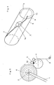
- a knife holder 10th provided with a knife 5, which, as shown in the figures 2, 4 and 6, is guided in a groove 7.
- the groove 7 runs from one edge 9 to the opposite edge below an angle to an axis-parallel generatrix. 8
- the knife 5 with its knife holder 10 must during its displacement movement from the edge 9 to the opposite edge the transport roller 4 with the peripheral speed of Transport roller 4 synchronized, that is, the knife movement is dependent on the peripheral speed the transport roller 4 controlled.
- FIG. 2 shows an embodiment of a transport roller, over which the knife holder 10 on a spindle 11th is guided by an electric spindle drive 12 in Rotation is offset.
- the knife holder 10 is so to speak a movable nut on the spindle 11.
- With 16 is an electrical Drive for the transport roller 4 and the both drives 12 and 16 are connected via a controller 13 in synchronizes the way that the knife holder 10 and thus the knife 5 in the groove 7 in response to the peripheral speed the transport roller 4 in its movement is controlled.
- the knife is the fifth guided by an edge of the groove 7, wherein a safety device 15 is provided, the insertion of the knife 5 in the Groove 7 allows.
- All three embodiments allow the cutting of a Material web when the corresponding winding is completed.
Landscapes
- Life Sciences & Earth Sciences (AREA)
- Forests & Forestry (AREA)
- Engineering & Computer Science (AREA)
- Mechanical Engineering (AREA)
- Replacement Of Web Rolls (AREA)
- Advancing Webs (AREA)
Abstract
Description
- Figur 1:
- eine Seitenansicht einer Transportwalze in Verbindung mit einem Wickel einer Materialbahn;
- Figur 2:
- eine schaubildliche Darstellung der Transportwalze in vergrößertem Maßstabe;
- Figur 3:
- eine, der Figur 1 entsprechende, Seitenansicht einer weiteren Ausführungsform einer Transportwalze;
- Figur 4:
- die Transportwalze aus Figur 3 in schaubildlicher Darstellung in vergrößertem Maßstabe;
- Figur 5:
- eine der Figur 1 und 3 entsprechende Darstellung einer dritten Ausführungsform einer Transportwalze; und
- Figur 6:
- die Transportwalze aus Figur 5 in schaubildlicher Darstellung und in vergrößertem Maßstabe.
Claims (16)
- Transportwalze (4) für Materialbahnen (3) mit einer außerhalb der Transportwalze (4) vorgesehenen Schneidvorrichtung (5) für die Materialbahn (3), dadurch gekennzeichnet, dass die Schneidvorrichtung mindestens ein Messer (5) aufweist, das beim Trennvorgang in einer Nut (7) der Transportwalze (4) in Längsrichtung derselben bewegbar geführt ist, die unter einem Winkel zu einer achsparallelen Mantellinie (8) der Transportwalze (4) verläuft und dass die Messerbewegung in Abhängigkeit von der Umfangsgeschwindigkeit der Transportwalze (4) steuerbar ist.
- Transportwalze nach Anspruch 1, dadurch gekennzeichnet, dass bei Verwendung eines einzigen Messers (5) die Nut (7) von einem Seitenrand der Transportwalze (4) zum gegenüber liegenden Rand verläuft.
- Transportwalze nach Anspruch 1 oder 2, dadurch gekennzeichnet, dass der Winkel, den die Nut mit der achsparallelen Mantellinie einschließt, konstant ist.
- Transportwalze nach Anspruch 1 oder 2, dadurch gekennzeichnet, dass der Winkel, den die Nut (7) mit der achsparallelen Mantellinie (8) einschließt, über die Länge der Nut (7) veränderlich ist.
- Transportwalze nach einem der Ansprüche 1 bis 4, dadurch gekennzeichnet, dass zum Antrieb des Messers (5) dieses über ein Getriebe (14) mit dem Transportwalzenantrieb (18) gekoppelt ist.
- Transportwalze nach einem der Ansprüche 1 bis 4, dadurch gekennzeichnet, dass der Antrieb (12) des Messers (5) ein elektrisches Stellglied umfasst, das über eine Regeleinrichtung (13) mit einem Stellglied des Transportwalzenantriebes (16) gekoppelt ist.
- Transportwalze nach einem der Ansprüche 1 bis 4, dadurch gekennzeichnet, dass der Antrieb des Messers (5) durch die Nutkante (7) nach Art eines Bewegungsgewindes erfolgt und dass am Anfang der Nut (7) eine Fangvorrichtung (15) für das Messer (5) vorgesehen ist.
- Transportwalze nach einem der Ansprüche 1 bis 7, dadurch gekennzeichnet, dass diese zwei sich kreuzende Nuten aufweist und dass zwei in entgegengesetzten Richtungen bewegbare Messer angeordnet sind.
- Transportwalze nach Anspruch 8, dadurch gekennzeichnet, dass der Kreuzungspunkt der beiden Nuten gleiche Abstände zu den Rändern der Transportwalze aufweist.
- Transportwalze nach Anspruch 8, dadurch gekennzeichnet, dass der Kreuzungspunkt der beiden Nuten ungleiche Abstände zu den Rändern der Transportwalze aufweist.
- Transportwalze nach einem der Ansprüche 8 bis 10, dadurch gekennzeichnet, dass zumindest zwei Abschnitte der sich kreuzenden Nuten bis zu jeweils einem Rand der Transportwalze verlaufen.
- Transportwalze nach einem der Ansprüche 8 bis 11, dadurch gekennzeichnet, dass die Nuten unter gleichen Winkeln zur achsparallelen Mantellinie verlaufen.
- Transportwalze nach einem der Ansprüche 8 bis 11, dadurch gekennzeichnet, dass die Nuten unter verschiedenen Winkeln zur Mantellinie verlaufen.
- Transportwalze nach einem der Ansprüche 8 bis 13, dadurch gekennzeichnet, dass die Messer unabhängig voneinander geführt sind.
- Transportwalze nach einem der Ansprüche 8 bis 14, dadurch gekennzeichnet, dass die Messer mit gleichen Geschwindigkeiten antreibbar sind.
- Transportwalze nach einem der Ansprüche 8 bis 14, dadurch gekennzeichnet, dass die Messer mit unterschiedlichen Geschwindigkeiten antreibbar sind.
Applications Claiming Priority (2)
| Application Number | Priority Date | Filing Date | Title |
|---|---|---|---|
| DE102004017471 | 2004-04-08 | ||
| DE200410017471 DE102004017471B3 (de) | 2004-04-08 | 2004-04-08 | Transportwalze für Materialbahnen |
Publications (2)
| Publication Number | Publication Date |
|---|---|
| EP1584427A1 true EP1584427A1 (de) | 2005-10-12 |
| EP1584427B1 EP1584427B1 (de) | 2013-12-25 |
Family
ID=34895537
Family Applications (1)
| Application Number | Title | Priority Date | Filing Date |
|---|---|---|---|
| EP20050006155 Expired - Lifetime EP1584427B1 (de) | 2004-04-08 | 2005-03-21 | Transportwalze und Querschneidvorrichtung für Materialbahnen |
Country Status (4)
| Country | Link |
|---|---|
| US (1) | US7370564B2 (de) |
| EP (1) | EP1584427B1 (de) |
| CA (1) | CA2503632C (de) |
| DE (1) | DE102004017471B3 (de) |
Cited By (2)
| Publication number | Priority date | Publication date | Assignee | Title |
|---|---|---|---|---|
| EP2127827A1 (de) * | 2008-05-26 | 2009-12-02 | Tang Yi-Lin | Elektrischer Folienschneider |
| CN110958985A (zh) * | 2017-07-31 | 2020-04-03 | 富士通先端科技株式会社 | 纸张存储设备 |
Families Citing this family (13)
| Publication number | Priority date | Publication date | Assignee | Title |
|---|---|---|---|---|
| AU2004100000A4 (en) | 2004-01-02 | 2004-02-12 | Sands Innovations Pty Ltd | Dispensing stirring implement |
| JP5560041B2 (ja) | 2007-01-31 | 2014-07-23 | サンズ イノベーションズ ピーティーワイ リミテッド | 分配用具及びその製造方法 |
| US7918152B2 (en) * | 2008-05-21 | 2011-04-05 | TANG Yi-lin | Electric cling film cutter |
| CA2746066A1 (en) | 2008-12-09 | 2010-06-17 | Sands Innovations Pty Ltd | A dispensing container |
| USD636890S1 (en) | 2009-09-17 | 2011-04-26 | Sands Innovations Pty. Ltd. | Dispensing utensil |
| US8511500B2 (en) | 2010-06-07 | 2013-08-20 | Sands Innovations Pty. Ltd. | Dispensing container |
| US8485360B2 (en) | 2011-03-04 | 2013-07-16 | Sands Innovations Pty, Ltd. | Fracturable container |
| CN103029154B (zh) * | 2012-11-19 | 2014-09-10 | 江苏海鸥食品机械制造有限公司 | 连续旋转式果蔬切瓣机 |
| CN108381612B (zh) * | 2018-01-19 | 2020-08-14 | 苏州矽美科导热科技有限公司 | 一种双向自动滑切装置 |
| JP7322584B2 (ja) | 2019-08-09 | 2023-08-08 | 株式会社リコー | シート加工装置、画像形成システム |
| JP7322582B2 (ja) | 2019-08-09 | 2023-08-08 | 株式会社リコー | シート加工装置、画像形成システム |
| CN112060170B (zh) * | 2020-09-02 | 2022-03-04 | 淮南宏阳工贸有限责任公司 | 一种自动化pvc塑料管道加工用切割设备 |
| DE102024110179B4 (de) * | 2024-04-11 | 2026-05-28 | Dr. Ing. H.C. F. Porsche Aktiengesellschaft | Vorrichtung und Verfahren zum Abtrennen eines Zuschnitts definierter Länge von einem mattenartigen Gegenstand |
Citations (4)
| Publication number | Priority date | Publication date | Assignee | Title |
|---|---|---|---|---|
| DE9303547U1 (de) * | 1993-03-11 | 1993-05-13 | Service-Technik Wolfertz GmbH, 5600 Wuppertal | Vorrichtung zum Zerteilen von bahnenförmigem Material |
| US5813305A (en) * | 1995-01-06 | 1998-09-29 | Intermec Corporation | Strip cutter for adhesive-backed media |
| US6003421A (en) * | 1997-08-15 | 1999-12-21 | Milich; Bruce | Apparatus and method for cutting elongated webs of material |
| US6190297B1 (en) * | 1998-12-04 | 2001-02-20 | Gerber Scientific Products, Inc. | Apparatus for cutting and creasing sheet material |
Family Cites Families (14)
| Publication number | Priority date | Publication date | Assignee | Title |
|---|---|---|---|---|
| US1555391A (en) * | 1925-02-28 | 1925-09-29 | Eva W Surfus | Automatic roll-skinning apparatus |
| US1967486A (en) * | 1932-11-21 | 1934-07-24 | Sexton Mfg Company | Bias-cutting machine |
| US2278029A (en) * | 1940-12-20 | 1942-03-31 | Russell E Walsh | Dispenser for sheet material |
| US2794488A (en) * | 1955-04-25 | 1957-06-04 | Du Pont | Film splicing machine |
| DE1912639B2 (de) * | 1969-03-13 | 1971-05-13 | Pototzki, Detlef, 4300 Essen | Vorrichtung zur abtrennung von einzelformularen von endlos formularsaetzen |
| DE2429055B1 (de) * | 1974-06-18 | 1975-07-31 | Barmag Barmer Maschinenfabrik Ag, 5600 Wuppertal | Vorrichtung zur Beseitigung von unerwünschten Aufspulungen von Kapillarfäden, Fäden oder Folienbändchen auf einer rotierenden Arbeitswalze |
| SE414883B (sv) * | 1978-05-25 | 1980-08-25 | Moelnlycke Ab | Sett och anordning for att skera till stycken av materialbanor |
| DE3004244C2 (de) * | 1980-02-06 | 1983-12-15 | Hans 5216 Niederkassel Lehmacher | Vorrichtung für die Herstellung von Kunststofftaschen |
| DE3004220C2 (de) * | 1980-02-06 | 1985-04-04 | Hans 5216 Niederkassel Lehmacher | Vorrichtung für die Herstellung von Kunststofftaschen |
| JPS60178159A (ja) * | 1984-02-22 | 1985-09-12 | Tokyo Sankei Kogyo Kk | ロ−ルに過誤巻着したフイルム等の除去方法 |
| US4679474A (en) * | 1985-12-06 | 1987-07-14 | Fmc Corporation | Cutting thermoplastic webs |
| JP3227837B2 (ja) * | 1992-10-20 | 2001-11-12 | ソニー株式会社 | シート体の連続巻取り方法及び連続巻取り装置 |
| JPH06218691A (ja) * | 1993-01-21 | 1994-08-09 | Fukuda Metal Foil & Powder Co Ltd | 断裁機 |
| FR2817796B1 (fr) * | 2000-12-11 | 2003-08-08 | Axiohm | Dispositif d'impression d'un ruban de papier et de decoupe du ruban en tickets imprimes |
-
2004
- 2004-04-08 DE DE200410017471 patent/DE102004017471B3/de not_active Expired - Fee Related
-
2005
- 2005-03-21 EP EP20050006155 patent/EP1584427B1/de not_active Expired - Lifetime
- 2005-04-04 CA CA002503632A patent/CA2503632C/en not_active Expired - Fee Related
- 2005-04-07 US US11/100,825 patent/US7370564B2/en not_active Expired - Fee Related
Patent Citations (4)
| Publication number | Priority date | Publication date | Assignee | Title |
|---|---|---|---|---|
| DE9303547U1 (de) * | 1993-03-11 | 1993-05-13 | Service-Technik Wolfertz GmbH, 5600 Wuppertal | Vorrichtung zum Zerteilen von bahnenförmigem Material |
| US5813305A (en) * | 1995-01-06 | 1998-09-29 | Intermec Corporation | Strip cutter for adhesive-backed media |
| US6003421A (en) * | 1997-08-15 | 1999-12-21 | Milich; Bruce | Apparatus and method for cutting elongated webs of material |
| US6190297B1 (en) * | 1998-12-04 | 2001-02-20 | Gerber Scientific Products, Inc. | Apparatus for cutting and creasing sheet material |
Cited By (2)
| Publication number | Priority date | Publication date | Assignee | Title |
|---|---|---|---|---|
| EP2127827A1 (de) * | 2008-05-26 | 2009-12-02 | Tang Yi-Lin | Elektrischer Folienschneider |
| CN110958985A (zh) * | 2017-07-31 | 2020-04-03 | 富士通先端科技株式会社 | 纸张存储设备 |
Also Published As
| Publication number | Publication date |
|---|---|
| US20050223865A1 (en) | 2005-10-13 |
| US7370564B2 (en) | 2008-05-13 |
| EP1584427B1 (de) | 2013-12-25 |
| CA2503632A1 (en) | 2005-10-08 |
| DE102004017471B3 (de) | 2005-11-17 |
| CA2503632C (en) | 2010-02-02 |
Similar Documents
| Publication | Publication Date | Title |
|---|---|---|
| EP1584427B1 (de) | Transportwalze und Querschneidvorrichtung für Materialbahnen | |
| DE3715229A1 (de) | Schneidkopf mit schneidmesser zum schneiden von flachmaterial | |
| DE602004006993T2 (de) | Schneidwerk für eine hülsen-wickelmaschine mit einem an einem rotierendem arm geführten schneider | |
| DE19543860A1 (de) | Verfahren und Vorrichtung zum Formen geschlitzter und gefalzter Kartonformteile | |
| DE2436717A1 (de) | Schlitz- und falzvorrichtung fuer durchlaufende materialbahnen | |
| EP2488322A1 (de) | Schneidvorrichtung mit variabler seitenführung | |
| DE3123183C2 (de) | ||
| DE4211217A1 (de) | Verfahren zum diskontinuierlichen erzeugen einer schnittlinie in flachmaterial | |
| DE3634198C2 (de) | ||
| DE10250433A1 (de) | Vorrichtung zum Verstellen von Zugrollen und/oder Schneidmesser an Falzapparaten | |
| DE2130543A1 (de) | Maschine zum Schneiden und Aufwickeln von Bandmaterial | |
| DE4138896C2 (de) | ||
| DE19953908A1 (de) | Hochgeschwindigkeitsschere zum Querteilen von Walzband | |
| DE19638307B4 (de) | Verfahren zum Schneiden von kontinuierlich geförderten, flächigen Produkten aus Papier oder ähnlichen Materialien | |
| DE202023100126U1 (de) | Schneidmessereinheit | |
| AT501246A1 (de) | Querschneidvorrichtung und -verfahren für bahnmaterial | |
| DE2236692A1 (de) | Geschwindigkeitsveraenderlicher antrieb | |
| DE20005601U1 (de) | Laufstreifenschneidmaschine mit rotierend angetriebenem Schneidmesser | |
| WO2017143373A1 (de) | Bearbeitungsanlage zum bearbeiten von rundmaterial umfassend eine zufördereinrichtung mit dauermagneten | |
| EP1099502A1 (de) | Hochgeschwindigkeitsschere zum Querteilen von insbesondere dünnem Walzband | |
| DE112005002885T5 (de) | Rill- und Faltmaschine zum Herstellen von Papier- und Buchbindegegenständen | |
| EP1724077A1 (de) | Längsschneidvorrichtung mit einer Zustelleinrichtung für Ober- und Untermesser | |
| DE2659478C3 (de) | Vorrichtung zum Beschneiden der Kanten einer Materialbahn | |
| DE2840299A1 (de) | Maschine zum geraderichten von metallischen draehten | |
| DE2341671A1 (de) | Elektroerodiermaschine |
Legal Events
| Date | Code | Title | Description |
|---|---|---|---|
| PUAI | Public reference made under article 153(3) epc to a published international application that has entered the european phase |
Free format text: ORIGINAL CODE: 0009012 |
|
| 17P | Request for examination filed |
Effective date: 20050718 |
|
| AK | Designated contracting states |
Kind code of ref document: A1 Designated state(s): AT BE BG CH CY CZ DE DK EE ES FI FR GB GR HU IE IS IT LI LT LU MC NL PL PT RO SE SI SK TR |
|
| AX | Request for extension of the european patent |
Extension state: AL BA HR LV MK YU |
|
| AKX | Designation fees paid |
Designated state(s): AT BE BG CH CY CZ DE DK EE ES FI FR GB GR HU IE IS IT LI LT LU MC NL PL PT RO SE SI SK TR |
|
| 17Q | First examination report despatched |
Effective date: 20070112 |
|
| GRAP | Despatch of communication of intention to grant a patent |
Free format text: ORIGINAL CODE: EPIDOSNIGR1 |
|
| INTG | Intention to grant announced |
Effective date: 20130724 |
|
| GRAS | Grant fee paid |
Free format text: ORIGINAL CODE: EPIDOSNIGR3 |
|
| GRAA | (expected) grant |
Free format text: ORIGINAL CODE: 0009210 |
|
| AK | Designated contracting states |
Kind code of ref document: B1 Designated state(s): AT BE BG CH CY CZ DE DK EE ES FI FR GB GR HU IE IS IT LI LT LU MC NL PL PT RO SE SI SK TR |
|
| RAP1 | Party data changed (applicant data changed or rights of an application transferred) |
Owner name: REIFENHAEUSER GMBH & CO. KG MASCHINENFABRIK |
|
| REG | Reference to a national code |
Ref country code: GB Ref legal event code: FG4D Free format text: NOT ENGLISH |
|
| REG | Reference to a national code |
Ref country code: CH Ref legal event code: EP |
|
| REG | Reference to a national code |
Ref country code: DE Ref legal event code: R081 Ref document number: 502005014136 Country of ref document: DE Owner name: HENNES, JOCHEN, DR., DE Free format text: FORMER OWNER: KIEFEL EXTRUSION GMBH, 67547 WORMS, DE |
|
| REG | Reference to a national code |
Ref country code: AT Ref legal event code: REF Ref document number: 646347 Country of ref document: AT Kind code of ref document: T Effective date: 20140115 |
|
| REG | Reference to a national code |
Ref country code: IE Ref legal event code: FG4D Free format text: LANGUAGE OF EP DOCUMENT: GERMAN |
|
| REG | Reference to a national code |
Ref country code: DE Ref legal event code: R096 Ref document number: 502005014136 Country of ref document: DE Effective date: 20140213 |
|
| REG | Reference to a national code |
Ref country code: CH Ref legal event code: NV Representative=s name: MODIANO AND PARTNERS S.A., CH |
|
| PG25 | Lapsed in a contracting state [announced via postgrant information from national office to epo] |
Ref country code: SE Free format text: LAPSE BECAUSE OF FAILURE TO SUBMIT A TRANSLATION OF THE DESCRIPTION OR TO PAY THE FEE WITHIN THE PRESCRIBED TIME-LIMIT Effective date: 20131225 Ref country code: FI Free format text: LAPSE BECAUSE OF FAILURE TO SUBMIT A TRANSLATION OF THE DESCRIPTION OR TO PAY THE FEE WITHIN THE PRESCRIBED TIME-LIMIT Effective date: 20131225 Ref country code: LT Free format text: LAPSE BECAUSE OF FAILURE TO SUBMIT A TRANSLATION OF THE DESCRIPTION OR TO PAY THE FEE WITHIN THE PRESCRIBED TIME-LIMIT Effective date: 20131225 |
|
| REG | Reference to a national code |
Ref country code: NL Ref legal event code: VDEP Effective date: 20131225 |
|
| REG | Reference to a national code |
Ref country code: LT Ref legal event code: MG4D |
|
| PG25 | Lapsed in a contracting state [announced via postgrant information from national office to epo] |
Ref country code: IS Free format text: LAPSE BECAUSE OF FAILURE TO SUBMIT A TRANSLATION OF THE DESCRIPTION OR TO PAY THE FEE WITHIN THE PRESCRIBED TIME-LIMIT Effective date: 20140425 Ref country code: EE Free format text: LAPSE BECAUSE OF FAILURE TO SUBMIT A TRANSLATION OF THE DESCRIPTION OR TO PAY THE FEE WITHIN THE PRESCRIBED TIME-LIMIT Effective date: 20131225 |
|
| PG25 | Lapsed in a contracting state [announced via postgrant information from national office to epo] |
Ref country code: PL Free format text: LAPSE BECAUSE OF FAILURE TO SUBMIT A TRANSLATION OF THE DESCRIPTION OR TO PAY THE FEE WITHIN THE PRESCRIBED TIME-LIMIT Effective date: 20131225 Ref country code: SK Free format text: LAPSE BECAUSE OF FAILURE TO SUBMIT A TRANSLATION OF THE DESCRIPTION OR TO PAY THE FEE WITHIN THE PRESCRIBED TIME-LIMIT Effective date: 20131225 Ref country code: CZ Free format text: LAPSE BECAUSE OF FAILURE TO SUBMIT A TRANSLATION OF THE DESCRIPTION OR TO PAY THE FEE WITHIN THE PRESCRIBED TIME-LIMIT Effective date: 20131225 Ref country code: NL Free format text: LAPSE BECAUSE OF FAILURE TO SUBMIT A TRANSLATION OF THE DESCRIPTION OR TO PAY THE FEE WITHIN THE PRESCRIBED TIME-LIMIT Effective date: 20131225 Ref country code: RO Free format text: LAPSE BECAUSE OF FAILURE TO SUBMIT A TRANSLATION OF THE DESCRIPTION OR TO PAY THE FEE WITHIN THE PRESCRIBED TIME-LIMIT Effective date: 20131225 Ref country code: PT Free format text: LAPSE BECAUSE OF FAILURE TO SUBMIT A TRANSLATION OF THE DESCRIPTION OR TO PAY THE FEE WITHIN THE PRESCRIBED TIME-LIMIT Effective date: 20140428 Ref country code: ES Free format text: LAPSE BECAUSE OF FAILURE TO SUBMIT A TRANSLATION OF THE DESCRIPTION OR TO PAY THE FEE WITHIN THE PRESCRIBED TIME-LIMIT Effective date: 20131225 Ref country code: CY Free format text: LAPSE BECAUSE OF FAILURE TO SUBMIT A TRANSLATION OF THE DESCRIPTION OR TO PAY THE FEE WITHIN THE PRESCRIBED TIME-LIMIT Effective date: 20131225 |
|
| REG | Reference to a national code |
Ref country code: DE Ref legal event code: R097 Ref document number: 502005014136 Country of ref document: DE |
|
| PG25 | Lapsed in a contracting state [announced via postgrant information from national office to epo] |
Ref country code: LU Free format text: LAPSE BECAUSE OF FAILURE TO SUBMIT A TRANSLATION OF THE DESCRIPTION OR TO PAY THE FEE WITHIN THE PRESCRIBED TIME-LIMIT Effective date: 20140321 Ref country code: DK Free format text: LAPSE BECAUSE OF FAILURE TO SUBMIT A TRANSLATION OF THE DESCRIPTION OR TO PAY THE FEE WITHIN THE PRESCRIBED TIME-LIMIT Effective date: 20131225 |
|
| PLBE | No opposition filed within time limit |
Free format text: ORIGINAL CODE: 0009261 |
|
| STAA | Information on the status of an ep patent application or granted ep patent |
Free format text: STATUS: NO OPPOSITION FILED WITHIN TIME LIMIT |
|
| REG | Reference to a national code |
Ref country code: CH Ref legal event code: PCAR Free format text: NEW ADDRESS: VIA CALLONI, 1, 6900 LUGANO (CH) |
|
| GBPC | Gb: european patent ceased through non-payment of renewal fee |
Effective date: 20140325 |
|
| 26N | No opposition filed |
Effective date: 20140926 |
|
| REG | Reference to a national code |
Ref country code: FR Ref legal event code: ST Effective date: 20141128 |
|
| REG | Reference to a national code |
Ref country code: IE Ref legal event code: MM4A |
|
| REG | Reference to a national code |
Ref country code: DE Ref legal event code: R097 Ref document number: 502005014136 Country of ref document: DE Effective date: 20140926 |
|
| PG25 | Lapsed in a contracting state [announced via postgrant information from national office to epo] |
Ref country code: GB Free format text: LAPSE BECAUSE OF NON-PAYMENT OF DUE FEES Effective date: 20140325 Ref country code: FR Free format text: LAPSE BECAUSE OF NON-PAYMENT OF DUE FEES Effective date: 20140331 Ref country code: IE Free format text: LAPSE BECAUSE OF NON-PAYMENT OF DUE FEES Effective date: 20140321 |
|
| REG | Reference to a national code |
Ref country code: AT Ref legal event code: MM01 Ref document number: 646347 Country of ref document: AT Kind code of ref document: T Effective date: 20140321 |
|
| PG25 | Lapsed in a contracting state [announced via postgrant information from national office to epo] |
Ref country code: SI Free format text: LAPSE BECAUSE OF FAILURE TO SUBMIT A TRANSLATION OF THE DESCRIPTION OR TO PAY THE FEE WITHIN THE PRESCRIBED TIME-LIMIT Effective date: 20131225 |
|
| PG25 | Lapsed in a contracting state [announced via postgrant information from national office to epo] |
Ref country code: AT Free format text: LAPSE BECAUSE OF NON-PAYMENT OF DUE FEES Effective date: 20140321 |
|
| PG25 | Lapsed in a contracting state [announced via postgrant information from national office to epo] |
Ref country code: MC Free format text: LAPSE BECAUSE OF FAILURE TO SUBMIT A TRANSLATION OF THE DESCRIPTION OR TO PAY THE FEE WITHIN THE PRESCRIBED TIME-LIMIT Effective date: 20131225 Ref country code: BG Free format text: LAPSE BECAUSE OF FAILURE TO SUBMIT A TRANSLATION OF THE DESCRIPTION OR TO PAY THE FEE WITHIN THE PRESCRIBED TIME-LIMIT Effective date: 20131225 |
|
| PG25 | Lapsed in a contracting state [announced via postgrant information from national office to epo] |
Ref country code: GR Free format text: LAPSE BECAUSE OF FAILURE TO SUBMIT A TRANSLATION OF THE DESCRIPTION OR TO PAY THE FEE WITHIN THE PRESCRIBED TIME-LIMIT Effective date: 20140326 |
|
| PG25 | Lapsed in a contracting state [announced via postgrant information from national office to epo] |
Ref country code: HU Free format text: LAPSE BECAUSE OF FAILURE TO SUBMIT A TRANSLATION OF THE DESCRIPTION OR TO PAY THE FEE WITHIN THE PRESCRIBED TIME-LIMIT; INVALID AB INITIO Effective date: 20050321 Ref country code: TR Free format text: LAPSE BECAUSE OF FAILURE TO SUBMIT A TRANSLATION OF THE DESCRIPTION OR TO PAY THE FEE WITHIN THE PRESCRIBED TIME-LIMIT Effective date: 20131225 Ref country code: BE Free format text: LAPSE BECAUSE OF FAILURE TO SUBMIT A TRANSLATION OF THE DESCRIPTION OR TO PAY THE FEE WITHIN THE PRESCRIBED TIME-LIMIT Effective date: 20140331 |
|
| PGFP | Annual fee paid to national office [announced via postgrant information from national office to epo] |
Ref country code: CH Payment date: 20170323 Year of fee payment: 13 |
|
| REG | Reference to a national code |
Ref country code: DE Ref legal event code: R082 Ref document number: 502005014136 Country of ref document: DE Representative=s name: FARAGO PATENTANWAELTE, DE Ref country code: DE Ref legal event code: R081 Ref document number: 502005014136 Country of ref document: DE Owner name: HENNES, JOCHEN, DR., DE Free format text: FORMER OWNER: REIFENHAEUSER GMBH & CO. KG MASCHINENFABRIK, 53844 TROISDORF, DE Ref country code: DE Ref legal event code: R082 Ref document number: 502005014136 Country of ref document: DE Representative=s name: FARAGO PATENTANWALTS- UND RECHTSANWALTSGESELLS, DE |
|
| PGFP | Annual fee paid to national office [announced via postgrant information from national office to epo] |
Ref country code: IT Payment date: 20170331 Year of fee payment: 13 |
|
| REG | Reference to a national code |
Ref country code: CH Ref legal event code: PCAR Free format text: NEW ADDRESS: VIA E. BOSSI 1, 6900 LUGANO (CH) Ref country code: CH Ref legal event code: PUE Owner name: JOCHEN HENNES, DE Free format text: FORMER OWNER: REIFENHAEUSER GMBH AND CO. KG MASCHINENFABRIK, DE |
|
| PGFP | Annual fee paid to national office [announced via postgrant information from national office to epo] |
Ref country code: DE Payment date: 20170330 Year of fee payment: 13 |
|
| REG | Reference to a national code |
Ref country code: DE Ref legal event code: R119 Ref document number: 502005014136 Country of ref document: DE |
|
| REG | Reference to a national code |
Ref country code: CH Ref legal event code: PL |
|
| PG25 | Lapsed in a contracting state [announced via postgrant information from national office to epo] |
Ref country code: DE Free format text: LAPSE BECAUSE OF NON-PAYMENT OF DUE FEES Effective date: 20181002 |
|
| PG25 | Lapsed in a contracting state [announced via postgrant information from national office to epo] |
Ref country code: LI Free format text: LAPSE BECAUSE OF NON-PAYMENT OF DUE FEES Effective date: 20180331 Ref country code: CH Free format text: LAPSE BECAUSE OF NON-PAYMENT OF DUE FEES Effective date: 20180331 Ref country code: IT Free format text: LAPSE BECAUSE OF NON-PAYMENT OF DUE FEES Effective date: 20180321 |