EP1584184B1 - Procede de traitement d'images cinematographiques deviees du trajet optique de prise de vues d'une camera cinematographique - Google Patents
Procede de traitement d'images cinematographiques deviees du trajet optique de prise de vues d'une camera cinematographique Download PDFInfo
- Publication number
- EP1584184B1 EP1584184B1 EP03810837A EP03810837A EP1584184B1 EP 1584184 B1 EP1584184 B1 EP 1584184B1 EP 03810837 A EP03810837 A EP 03810837A EP 03810837 A EP03810837 A EP 03810837A EP 1584184 B1 EP1584184 B1 EP 1584184B1
- Authority
- EP
- European Patent Office
- Prior art keywords
- assist
- image
- moving picture
- picture camera
- camera
- Prior art date
- Legal status (The legal status is an assumption and is not a legal conclusion. Google has not performed a legal analysis and makes no representation as to the accuracy of the status listed.)
- Expired - Fee Related
Links
Images


Classifications
-
- H—ELECTRICITY
- H04—ELECTRIC COMMUNICATION TECHNIQUE
- H04N—PICTORIAL COMMUNICATION, e.g. TELEVISION
- H04N5/00—Details of television systems
- H04N5/76—Television signal recording
- H04N5/765—Interface circuits between an apparatus for recording and another apparatus
- H04N5/77—Interface circuits between an apparatus for recording and another apparatus between a recording apparatus and a television camera
-
- H—ELECTRICITY
- H04—ELECTRIC COMMUNICATION TECHNIQUE
- H04N—PICTORIAL COMMUNICATION, e.g. TELEVISION
- H04N5/00—Details of television systems
- H04N5/222—Studio circuitry; Studio devices; Studio equipment
-
- H—ELECTRICITY
- H04—ELECTRIC COMMUNICATION TECHNIQUE
- H04N—PICTORIAL COMMUNICATION, e.g. TELEVISION
- H04N5/00—Details of television systems
- H04N5/222—Studio circuitry; Studio devices; Studio equipment
- H04N5/2228—Video assist systems used in motion picture production, e.g. video cameras connected to viewfinders of motion picture cameras or related video signal processing
-
- H—ELECTRICITY
- H04—ELECTRIC COMMUNICATION TECHNIQUE
- H04N—PICTORIAL COMMUNICATION, e.g. TELEVISION
- H04N5/00—Details of television systems
- H04N5/222—Studio circuitry; Studio devices; Studio equipment
- H04N5/262—Studio circuits, e.g. for mixing, switching-over, change of character of image, other special effects ; Cameras specially adapted for the electronic generation of special effects
-
- H—ELECTRICITY
- H04—ELECTRIC COMMUNICATION TECHNIQUE
- H04N—PICTORIAL COMMUNICATION, e.g. TELEVISION
- H04N5/00—Details of television systems
- H04N5/76—Television signal recording
- H04N5/765—Interface circuits between an apparatus for recording and another apparatus
-
- H—ELECTRICITY
- H04—ELECTRIC COMMUNICATION TECHNIQUE
- H04N—PICTORIAL COMMUNICATION, e.g. TELEVISION
- H04N5/00—Details of television systems
- H04N5/76—Television signal recording
- H04N5/765—Interface circuits between an apparatus for recording and another apparatus
- H04N5/775—Interface circuits between an apparatus for recording and another apparatus between a recording apparatus and a television receiver
-
- H—ELECTRICITY
- H04—ELECTRIC COMMUNICATION TECHNIQUE
- H04N—PICTORIAL COMMUNICATION, e.g. TELEVISION
- H04N5/00—Details of television systems
- H04N5/76—Television signal recording
- H04N5/78—Television signal recording using magnetic recording
- H04N5/781—Television signal recording using magnetic recording on disks or drums
-
- H—ELECTRICITY
- H04—ELECTRIC COMMUNICATION TECHNIQUE
- H04N—PICTORIAL COMMUNICATION, e.g. TELEVISION
- H04N9/00—Details of colour television systems
- H04N9/79—Processing of colour television signals in connection with recording
- H04N9/80—Transformation of the television signal for recording, e.g. modulation, frequency changing; Inverse transformation for playback
- H04N9/804—Transformation of the television signal for recording, e.g. modulation, frequency changing; Inverse transformation for playback involving pulse code modulation of the colour picture signal components
- H04N9/8042—Transformation of the television signal for recording, e.g. modulation, frequency changing; Inverse transformation for playback involving pulse code modulation of the colour picture signal components involving data reduction
Definitions
- the invention relates to a method for processing film images branched off from a film recording beam path of a motion picture camera according to the preamble of claim 1 and to an apparatus for carrying out the method.
- EP 0 963 113 A is a video-assisted system with an integrated standards converter for video images for converting the video standard of the given by a CCD sensor NEN digital video signal, which includes a memory for storing the digital video signal, an address generator for generating memory addresses and an interpolator for interpolating the memory stored at the memory addresses stored data and outputs after the standards conversion, a serial digital video signal having a standard video image frequency.
- a video device for a motion picture camera in which a video image sensor is arranged in an optical beam path of the motion picture camera, which is interrupted periodically in dependence on the image recording frequency of the motion picture camera.
- a video device is used to generate parallel to the exposure of film images of the motion picture film, a video image, on the one hand during the movie recording allows viewing independently of the view of the camera viewfinder and on the other to facilitate the post-processing of the exposed motion picture film based on the recorded video sequences.
- a part of the recording beam path of the motion picture camera is branched off into a video beam path and fed to a video image sensor or a video camera.
- the shooting lens of the motion picture camera designs a picture in the picture level of the motion picture film intermittently moving, for example, with a film transport speed of 24 frames per second, when a rotating mirror aperture arranged in the recording beam path of the motion picture camera behind the photographing lens releases the recording beam path during the exposure of a film frame.
- the movable playing glare obscures the recording beam path to the image plane and directs the film image onto the plane of a ground glass or fiber plate, from which the resulting image is imaged via video optics on a video image sensor.
- the video image sensor integrates the light falling on its photosensitive layer of the video beam path.
- the integrated signals are periodically read from the video image sensor and displayed as video output signals on a video monitor or stored on a suitable storage medium.
- At least one further beam splitter which branches off the image of the ground glass or fiber plate to an eyepiece, through which a cameraman can view the film image on the ground glass.
- the respective period of effective exposure for one pixel of the charge image of the video image sensor between erasure readout of the charge image for generating the video output signal and the next erasive readout of the charge image for generating the next video output signal is different from image to image, since the usual image acquisition frequency of a motion picture camera only in exceptional cases coincides with the video frequency of the video device.
- the image-taking frequency of a motion picture camera is usually 24 frames per second, while the video frequency of a video device is 50 frames per second in a PAL system and 60 frames per second in an NTSC system. This flickering affects the lightness / darkness of a video image or video field to the next, which makes the video image viewing difficult or impossible.
- the film transport speed or image recording frequency of the motion picture camera thus corresponds to the video output signal of the known video device of the standard video frame rate and at the output of the video device in the form of a composite video signal (Farbart-, Schminhalt-, blanking and synchronizing signal) for display on a video monitor or for video signal storage.
- a major disadvantage of this rigid video assist system is that the production and output of standards-compliant video images on the peculiarities of a motion picture film is not discussed. This leads to problems in the post-processing of the motion picture film and to avoid special effects that are generated with the motion picture film, but with the video device for the following reasons can not be displayed.
- the standard image pickup frequency of a motion picture camera is 24 fps
- the post-processing of a motion picture film and in particular for the film cut editing computer are already known, which operate with a temporal resolution of 24 frames per second, so that when using a video recording to facilitate the Post-processing of the motion picture film first the video signal depending on the respective System (PAL or NTSC) with a video frequency of 25 or 30 video frames per second to the image recording frequency of the motion picture camera of 24 frames per second to be converted.
- PAL or NTSC respective System
- the rigid, standard video frame rate does not allow for the reproduction of slow motion or fast motion effects of a motion picture film which has been exposed at an image acquisition frequency other than the standard frame rate.
- the motion picture camera is moved to produce a slow-motion effect with a higher transport speed or to generate a time-lapse effect with a lower film transport speed than the standard film transport speed or image recording frequency. If the motion picture film is moved again at the normal standard image recording frequency of 24 images per second during projection, the corresponding slow-motion and time-lapse effects are realized. These effects can only be displayed inadequately because of the rigid, standard-compliant video picture frequency.
- the object of the present invention is to specify a method for processing film images branched off from a film recording beam path of a motion picture camera, which is adapted to the special features of a motion picture camera and, in particular, guarantees a flawless presentation of special effects produced by a motion picture film, such as slow-motion and time-lapse recordings.
- the solution according to the invention ensures processing of film images derived from a film recording beam path of a motion picture camera adapted to the particular features of a motion picture camera, and in particular enables the flawless presentation of special effects produced by a motion picture film, such as slow-motion and time-lapse recordings, in particular while maintaining a full-screen resolution.
- the solution according to the invention is based on the consideration, in contrast to the known methods for standard-compliant preparation of video signals for the flicker-free display of video images or video fields parallel to each film image to output an electronic, preferably digital Assistsent. Since this method breaks with the standards for video picture signals, the format implementing this method must be a special, preferably a digital format. However, since this format can not be displayed on commercially available video recorders or video monitors, the digital assistsignal is delivered to a data processing device in which or from the electronic assisted image is displayed or stored on a monitor. This makes it possible to use electronic assist images, for example at 35 frames per second, i. as a slight slow motion to the data processing device to transfer.
- the assist images are first displayed and / or recorded in real time, that is to say exactly as the scene recorded by the motion picture camera. Furthermore, the stored scene can then be reproduced again either in real time or assuming a viewing speed of, for example, 24 frames per second depending on the recording speed as slow motion or fast motion.
- digital assist signals with a frame frequency matching the image recording frequency of the motion picture camera are delivered to a data processing device which processes assist images formed from the digital assist signals with the image recording frequency of the motion picture camera.
- the data processing device outputs the digital assists signals for displaying the assist images with an assist image frequency or the image acquisition frequency the motion picture camera to a digital storage device or with a normalized frame rate, for example 24 frames per second, to a monitor.
- the assist images may be passed out of the data processing device as digital video signals, CVBS or Y / C signals to display or digital or analog storage devices.
- An advantageous variant of the method according to the invention is characterized by a separate, a previously known video assist video branch corresponding in the usual video signals with a video standard corresponding video signal frequency via a standard interface to conventional video equipment such.
- B. video monitors and video recorders are sent.
- the electronic image signals or digital assistsignals can be delivered to the data processing device at a frame rate matching the image recording frequency of the motion picture camera.
- a CVBS, Y / C and DV signal with 25 or 30 full Assistbildem per second output via conventional interfaces from the first signal path, while in the second signal path, an electronic assist image per film image is output to the data processing device, so that both a flicker-free standard operation as well as a parked on the special features and possibilities of the motion picture camera operating mode can be used.
- camera and assist control information for the motion picture camera or a camera assist device integrated in the motion picture camera can be sent by the data processing device, while conversely on a meta data channel additional recording, control or status signals or Data such as camera status information can be sent back to the data processing device, so that, for example, a mode is created which automatically records the assist images in the data processing device when the motion picture camera is running.
- an overlay of selectable control, status and / or recording data into the image can be provided for additional information, for example during the post-processing of a motion picture film.
- the overlay can either be superimposed on the image content, so that it also remains when saving the information from the data processing device out on classic video systems, or displayed next to the actual image content on free areas of a monitor. Since the metadata are stored parallel to the actual Assist images in the data processing device, they can be displayed within this unit again and again, even outside the actual image area.
- the data processing device takes over the clearly legible display of important data in the Assist image or on the Assist monitor and can the data as standard-compliant video signal z. B. to a VCR or video monitor or directly by file copy, so do not deliver as a video signal to a provided for post-processing of the motion picture film editing computer.
- a preferred embodiment of the method according to the invention is characterized in that the light conditions in the assist beam path of the motion picture camera are represented by corresponding diaphragm index signals, which are output to the optoelectronic transducer via an aperture index signal conditioning, which in dependence on the processed diaphragm index signals in a first exposure mode, the amount of light in Assist beam path integrated from a dark phase of the assist beam path to the next dark phase, the integrated amount of light is read out after the end of the integration of an image processing device.
- the exposure time of the optoelectronic transducer is set to a predeterminable value, preferably the film exposure time of the motion picture camera, the amount of light of the assist beam path from a start value in the light phase to a final value integrated in this light phase and the integrated amount of light after the end of the integration , which corresponds in time to the predetermined value, read by the image processing device.
- the center of the set exposure time of the optoelectronic transducer can be set to the middle of the light phase in the assist beam path.
- a merger of multiple blend passes to an assist image is provided.
- the digital assist image is calculated, decoding the color mask of the optoelectronic transducer in a single optoelectronic transducer, and combining the images of the optoelectronic transducers in a plurality of optoelectronic transducers.
- the image data of the digital assist images are delivered to an image compression device which compresses the image data of the digital assist images and outputs via line driver depending on the image recording frequency of the motion picture camera to the data processing device, which stores the image data of the digital assist images, decompressed and displayed on an external or internal monitor controlled by a timing control.
- the monitor is a conventional computer monitor with VGA or XVGA input.
- the signal and data exchange between the camera assist device and the data processing device is preferably binary coded, in particular as a PCM signal (Pulse Code Modulation), wherein the signals and data are wired, transmitted via optical fibers or glass fibers, by means of a carrier frequency system or via an infrared interface ,
- PCM signal Pulse Code Modulation
- a device for carrying out the method is characterized by a camera assist device with an image sensor directed towards the assist beam path and a data processing device which receives the digital assist signals output by the camera assist device at a frame rate matching the image recording frequency of the motion picture camera and those from the digital assist signals compiled digital assist images with the image recording frequency of the motion picture camera processed.
- the data processing device is connected to a digital storage device and / or a monitor and consists of a personal computer (PC) on whose monitor the electronic images can be viewed.
- PC personal computer
- the transmission of the electronic images from the assisting device to the personal computer can take place in particular via a fire-wire interface of the personal computer, so that no additional hardware requirements for carrying out the method according to the invention are to be fulfilled.
- it is especially useful for the flexible transmission of electronic images without fixed frame rates an independent transmission systems.
- the assist beam path of the motion picture camera image sensor can either a CCD chip, a C-MOS image sensor or a picture tube are used, which work especially in progressive scan mode, although the use of an interlaced chip is also possible in principle.
- a further advantageous embodiment is characterized by an input field for operating settings, which are executed via graphically illustrated operating elements of the camera assist device. For example, specifications on the signal amplification, the color setting, the exposure mode and possibly the settings of the motion picture camera can be made on the input field.
- the data Via a return line to the camera assist device of the motion picture camera, the data are delivered to a controller of the camera assist device, from where they act on the image sensor or the image processing or are made available via a corresponding interface as camera control signals of the motion picture camera.
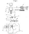
- FIG. 1 schematically illustrated optical system of a motion picture camera 1 with a camera assist device 2, 3 shows a taking lens 10, through which a recording beam S1 enters the motion picture camera 1 and strikes a rotating mirror aperture 11.
- the rotating mirror aperture 11 is usually composed of a semicircular mirror surface with a circumferential angle of usually 180 ° and a coaxial with the mirror surface arranged Aperture, which is adjustable relative to the mirror surface, so that aperture angle of 0 ° to 180 ° of the rotating mirror aperture 11 can be adjusted ,
- the rotating mirror aperture 11 of the receiving beam path S1 Depending on the angular position of the rotating mirror aperture 11 of the receiving beam path S1 hits the opening sector (bright sector) of the rotating mirror aperture 11 and passes through an image window 12 on a run in a film channel motion picture film 13.
- the image window 12 through the mirror surface of covered by the rotating mirror aperture 11 and the recording beam path S1 deflected to a ground glass or fiber plate 14, from where the receiving beam path S1 passes through a first beam splitter 15, of the receiving beam path S1 splits a viewfinder beam S3 into an eyepiece 16, through which the cameraman can view the image on the ground glass or fiber plate 14.
- the beam part S2 of the recording beam path S1 passing through the first beam splitter 15 possibly still reaches a second beam splitter 17, which splits the beam part S2 into a light meter beam path S5 for a light meter 18 and an assist beam path S4.
- the assist beam path S4 passes through an assist optics 19 to the camera assist device with an image sensor 2, which converts the optical image into image signals, and with an assist electronics 3, which generates digital signals from the image signals and the assists signals AS and possibly other control signals and data issues a personal computer 4 and receives control and data signals ASS, CS from the personal computer 4.
- the assist electronics 3 are further supplied with a mode select signal MS from the personal computer 4, which specifies a desired exposure mode, and a diaphragm index signal BI from the camera, which corresponds to the respective exposure conditions of the assist beam path S4 and thus the exposure conditions on the image sensor 2. Furthermore, the assist electronics 3 outputs camera control signals CC to the control electronics of the motion picture camera 1.
- the assist electronics 3 offers according to the Fig. 2 and 5 the possibility of connecting a monitor 35 on which the assist images composed of the digital assistance signals can be viewed directly on the motion picture camera.
- the personal computer 4 has, in addition to an input keyboard, an internal or external memory and a monitor, as well as output ports for outputting a CVBS, Y / C and DV (Digital Video) signal and a signal BD containing image data.
- the composite color, picture, blanking and sync signal FBAS is created by combining the luminance and chrominance signals.
- the Y / C signal corresponds to the two portions of the luminance Y and chrominance C of the entire color video signal transmitted separately on separate lines.
- the DV signal is a digital recording format, such as in recent times with consumer video recorders or Consumer camcorders is used. It can be recorded on devices that have corresponding inputs.
- FIG. 2 Block diagram shown shows the functional structure of the assist 3 and the image processing part of the personal computer. 4
- the camera assist device usually arranged in the camera head of the motion picture camera contains the image sensor 2, to which the assist beam path S4 according to FIG Fig. 1
- the output of the image sensor 2 is connected to an image processing device 32, which calculates a digital, color image from the output signals of the image sensor 2.
- the output of the image processing device is connected to an image compression device 33, which performs data compression in order to minimize the amount of data to be transmitted to the personal computer 4.
- the data compressed by the image compression means 33 are transmitted in a computer-usual format as a series of frames to the personal computer 4.
- a control device 30 establishes a connection between the camera control and the camera electronics 3 and outputs the input in an input field for operating settings 46 of the personal computer 4 specifications on the signal gain, the color setting, possibly settings of the motion picture camera 1, etc. to the image sensor. 2 and the image processing device 32, which receives them as control signals ASS and CS from the personal computer 4 via the line driver 34.
- An aperture index signal processing 31 is input side with the aperture index signal BI, which represents the exposure cycle of the motion picture camera 1, and a mode select signal MS applied by the PC, which specifies the respectively desired exposure mode.
- the aperture index signal conditioning 31 with a processed aperture index signal controls the timing of the image sensor 2 and the integration time TI as a function of the exposure cycle of the motion picture camera 1.
- a signal output is provided on the image data, preferably in VGA or XVGA format, onto a corresponding monitor 35, preferably a flat screen.
- the image processing part of the personal computer 4 includes an image memory unit 41 in which the digital assist signals AS transmitted via the line drivers 34 of the assist electronics 3 are stored as a series of frames in a computer-usual format.
- the image storage unit 41 may consist, for example, of the hard disk of the personal computer 4.
- the output of the image storage unit 41 is connected to an image processing device 42 in which the still compressed data of the series of individual images are decompressed and processed.
- An output of the rendering device 42 is connected to a graphics card 43 which converts the series of frames into a graphical representation for display on a monitor 44 of the personal computer 4.
- the display of images on the monitor of the PC is not necessarily dependent on the motion picture camera. Usually, the display is made from here in the frequency specified by the graphics card.
- a timing controller 40 controls the image processing device 42 so that, for example, the series of individual assist images currently output by the assisting electronics 3 with the digital assist signals AS are processed in time with the timing of the motion picture camera and controlled for direct viewing on the monitor 44.
- Another output of the image processing device 42 is connected to an image converter 45, which outputs a composite video signal, Y / C signal, DV signals and image data to further display devices and / or video memory devices or video recorder.
- a specification on the PC determines how different film speeds should be used. In a first software mode the images are always transferred to the video systems as in real recording time, in a second mode the images are always related to the film exposure time of the motion picture camera (screen time).
- the camera assist device accordingly produces 15 electronic (assist) frames per second.
- 15 electronic frames become 50 fields.
- the first electronic assist image becomes three assisted fields
- the second electronic image becomes three assisted fields
- the third electronic image becomes four assisted fields.
- the video frequency specifies a specific time frame.
- the electronic assist images are repeated as assisted frames until a new electronic assist image is available.
- assist frames are skipped accordingly.
- the second mode is based on the assumption that the images are recorded at 15 frames per second with the motion picture camera, but in the playback with z. 24 frames per second, ie with a time lapse of 24/15.
- the 15 pictures would be shown in the cinema in 15/24 seconds, ie 0.625 seconds. This corresponds to 31.25 video fields.
- 60 electronic pictures become 125 assisted fields.
- the first electronic image becomes two fields
- the second electronic image becomes two fields, and so on, up to the twelfth electronic image, which becomes three fields.
- the personal computer 4 contains an input field 46 for operating settings, which outputs the control signals ASS and CS via the line driver 34 to the control device 30 of the assist electronics 3 for specifying the gain, color setting and the exposure mode and optionally of settings of the motion picture camera.
- the input via the input field 46 of the personal computer 4 input control signals are processed and delivered as control signals VC to the image sensor 2 and the image processing device 32 or provided via a corresponding interface as camera control signals CC of the motion picture camera available.
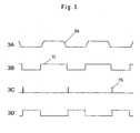
- the incident on the image sensor 2 Assist beam path S4 is converted into electronic image signals ( Fig. 3A and 4A ) and controlled by the controller 30 and the aperture index signal conditioning 31 to the image processing device 32.
- the diaphragm index signal processing acted upon by the diaphragm index signals BI 31 steepens the received aperture index signals via a Schmitt trigger and performs a phase shift of the received aperture index signals BI. This results in the time during which the assist beam path S4 according to Fig. 1 on the image sensor 2 reaching light from the image sensor 2 is integrated, depending on the aperture index signals BI and thus of the existing in the assist beam S4 light and the selected exposure mode.
- a first adjustable by means of the mode select signal MS exposure mode the reaching of the image sensor 2 light from a dark phase over the period of light phase, in which in the Assiststtahlengang S4 light is present until the next dark phase in the again no light in the assist beam S4 is present, according to Fig. 3B integrated.
- This first exposure mode leads to maximum bright assist images.
- the time at which the integration of the light is terminated by the image sensor 2 and then immediately started again irrelevant, as long as this time is in the dark phase of the assist beam path S4 and thus ensures that no unwanted light of a blind passage on the image sensor. 2 arrives.
- the area of the end of integration can be placed in the middle of the dark phase of the assist beam path S4, which is not mandatory for the function in the first exposure mode.
- the image sensor 2 in this mode will almost always be photosensitive. Only for a short time, the reading of the image sensor 2 is started according to a transfer signal TS. After the information has been read out in the image sensor, it becomes photosensitive again.
- a in Fig. 3C represented signal read out the photosensitive layer of the image sensor 2.
- the start of the read-out according to the transfer signal TS can be done immediately after the end of the by the in Fig. 3B illustrated signal-controlled integration of the light begin.
- Fig. 3D shows the output from the image sensor 2 to the image processing device 32 signal of the photosensitive layer of the image sensor 2. It corresponds to the time in which an electronic image is read out of the sensor.
- the image sensor 2 After the end of the readout of the photosensitive layer of the image sensor 2, the image sensor 2 is deleted or is already deleted depending on the design of the image sensor 2. Subsequently, a new integration of the incident light in the assist beam S4 light by the image sensor 2 begin.
- the output signals of the image sensor 2 are emitted as a function of the exposure cycle of the motion picture camera 1 from the image sensor 2 to the image processing device 32, where from the output signals of the image sensor 2, a digital, color correct image is calculated.
- the color mask of the chip is decoded, whereas in the case of image sensors with a plurality of chips, the images are combined in a manner known per se.
- the digital images are available in computer-usual formats as a series of individual images.
- the individual digital assist images computed by the rendering device 32 are compressed in the image compression 33 using a data compression method in order to minimize the amount of data to be transmitted for the individual digital assist images.
- the compressed image data is transmitted via line driver 34 to the personal computer 4 depending on the timing of the motion picture camera 1.
- the compressed image data is stored, for example, on the hard disk of the personal computer 4 and decompressed and processed in the image processing device 42.
- the graphics card 43 Via the graphics card 43, the decompressed and graphically processed data on the monitor 44 of the personal computer. 4 displayed.
- the decompression and conditioning of the image data as well as the conversion in the graphics card 43 is controlled by the timing controller 40.
- This timing generator is not necessarily coupled to the frequency of the transmitted assist images.
- the transmitted digital assist images which correspond to the individual film images, can thus be reproduced on the monitor 44 at different speeds, so that, for example, the effect of a special recording effect, such as a slow motion or a time-lapse, can be realistically simulated.
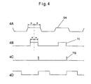
- the light-sensitive layer of the image sensor 2 is exposed to a significantly shorter exposure time, the exposure time being determined by the respective desired or set exposure time. This will usually be the exposure time of the motion picture film in the motion picture camera 1.
- the camera assist device can follow this setting of the exposure time of the motion picture film 13 and thus an assessment of this Real effect.
- Fig. 4A shows the sequence of light occurring in Assiststrahlengang S4 light. Subsequently, as described, the exposure time TI effective for the image sensor 2 is determined after a phase shift. The exposure time is usually shorter than easily in the assist beam S4 is present.
- the further waveform in the second exposure mode corresponds to the above with reference to the Fig. 3 described course of the first exposure mode.
- FIG. 5 Block diagram shown shows the functional structure of an advantageous development of the assist electronics 3 and the image processing part of the personal computer 4, all in the Fig. 2 illustrated components in this development perform the same function and are therefore provided with the same reference numerals and are used in parallel to the Assistzweig described above, so that a re-description is omitted here.
- a signal path branches off to a memory unit 36, which consists of an amplifier, an A / D Converter, an image memory and a D / A converter consists.
- the signals of the image sensor 2 are output from the image sensor 2 controlled by the light / dark phases in the assist beam path S4, amplified and converted into digital assist signals.
- These digital assist signals are read into the image memory, still in dependence on the light / dark phases in the assist beam path S4.
- the digital assist signals are read out with the frequency of the desired system, ie with 50 frames per second in PAL systems and 60 full frames per second in an NTSC system.
- the digital assist signals are converted back to analog signals via a D / A converter and then converted to regular video signals by video circuitry known from video cameras.
- the video circuit together with an image inserter, through which additional data can be faded into the video image, designated by the reference numeral 37.
- the video signals still pass through an output stage 38 in order to use common interfaces, for. B. a 75 ohm BNC output for CVBS signal can be used. These outputs, can also be diverted again for a small video monitor 39, it is not important which of the output signals is used.
- the additional video monitor 39 in parallel to the output for the monitor 35 has the advantage that in the described embodiment, both pure video monitors and VGA monitors can be connected.
- the combination of the known embodiment with analog video outputs and the variable transmission speed digital signal variant according to the invention offers the user the possibility of being able to display and record scenes in which no speed effects occur without the additional personal computer 4.
- the personal computer 4 is thus only connected if it because Speed effects or the better quality of digital images is necessary.
- Motion picture camera 2 Opto-electronic converter 3 Assist electronics 4 Personal computer 5 Fire-Wire Interface 10 taking lens 11 rotating mirror aperture 12 picture window 13 Motion picture film 14 Ground glass or fiber board 15 First beam splitter 16 eyepiece 17 second beam splitter 18 light meter 19 Assist optics 30 control device 31 Aperture index signal conditioning 32 Renderer 33 Image compression device 34 line driver 35 monitor 36 storage unit 37 Video circuit and image inserter 38 output stage 39 video monitor 40 timing control 41 Image storage unit 42 Renderer 43 graphic card 44 monitor 45 Image conversion device S1 Recording beam path S2 beamlet S3 Finder beam path S4 Assist beam path S5 Exposure meter beam path ABI processed aperture index signal BD Image data containing signal BI Aperture index signal CC Camera control signals AS Assist control signal DV Digital video signal composite Color, picture, blanking and synchronizing signal VC control signal AS Digital assists signal ASS Assist-control signal Y / C Luminance and chrominance signal
Claims (31)
- Procédé de traitement d'images cinématographiques dérivées du trajet du faisceau d'enregistrement cinématographique (S1) d'une caméra de prise de vue (1), lesdites images étant converties en signaux auxiliaires numériques (AS) à l'aide d'un convertisseur optoélectronique (2) qui est disposé sur un trajet du faisceau optique (S4) de la caméra de prise de vue (1), ledit trajet étant interrompu périodiquement en fonction de la fréquence d'enregistrement d'image de la caméra de prise de vue (1),
caractérisé en ce que
la fréquence d'enregistrement d'image de la caméra de prise de vue (1) est variable, et en ce que les signaux auxiliaires numériques (AS) sont délivrés, à une fréquence d'image, coïncidant avec la fréquence d'enregistrement d'image de la caméra de prise de vue (1), à un dispositif de traitement de données (4) qui traite des images auxiliaires dérivées des signaux auxiliaires numériques (AS) à la fréquence d'enregistrement d'image de la caméra de prise de vue (1). - Procédé selon la revendication 1, caractérisé en ce que le dispositif de traitement de données (4) délivre les signaux auxiliaires numériques (AS), pour afficher les images auxiliaires, à une fréquence d'image auxiliaire ou à la fréquence d'enregistrement d'image de la caméra de prise de vue (1), à un dispositif de stockage numérique.
- Procédé selon la revendication 1, caractérisé en ce que le dispositif de traitement de données (4) délivre les signaux auxiliaires numériques (AS) pour afficher les images auxiliaires à une fréquence d'image normalisée, par exemple de 24 images/s, à un moniteur (44).
- Procédé selon au moins une des revendications précédentes, caractérisé en ce que sur un premier trajet de signal, les signaux vidéo sont amenés, à une fréquence de signal vidéo correspondant à la norme vidéo, par l'intermédiaire d'une interface normalisée à des interfaces vidéo usuelles.
- Procédé selon la revendication 4, caractérisé en ce que sur un deuxième trajet de signal, les signaux auxiliaires numériques (AS) sont délivrés, à une fréquence de signal coïncidant avec la fréquence d'enregistrement d'image de la caméra de prise de vue (1), au dispositif de traitement de données (4).
- Procédé selon au moins une des revendications précédentes, caractérisé en ce qu'à une fréquence d'enregistrement d'image de la caméra de prise de vue (1) qui est supérieure au débit de données maximal à transmettre ou réalisable par le convertisseur optoélectronique, une image auxiliaire sur deux, ou multiple, est délivrée au dispositif de traitement de données (4).
- Procédé selon au moins une des revendications précédentes, caractérisé en ce que le dispositif de traitement de données (4) transmet des signaux de commande auxiliaires (ASS) à la caméra de prise de vue (1) par l'interface (5).
- Procédé selon au moins une des revendications précédentes, caractérisé en ce que la caméra de prise de vue (1) transmet des signaux supplémentaires d'enregistrement, de commande ou d'état (CS) au dispositif de traitement de données (4) par l'interface (5).
- Procédé selon au moins une des revendications précédentes, caractérisé en ce que des données sélectionnables de commande, d'état et/ou d'enregistrement sont incrustées comme des métadonnées dans l'image auxiliaire.
- Procédé selon la revendication 9, caractérisé en ce que les métadonnées sont affichées en dehors de la zone d'image sur un moniteur.
- Procédé selon au moins une des revendications précédentes, caractérisé en ce que des signaux d'indice de diaphragme (BI) correspondant aux conditions de lumière sur la trajectoire du faisceau auxiliaire (S4) de la caméra de prise de vue (1) sont délivrés, par l'intermédiaire d'un dispositif de conditionnement de signal d'indice de diaphragme (31), au convertisseur optoélectronique (2) qui, en fonction des signaux d'indice de diaphragme conditionnés, intègre pour son temps d'intégration (TI) dans un mode d'exposition prédéfini la lumière sur la trajectoire du faisceau auxiliaire (S4), et en ce que la quantité de lumière intégrée est extraite à l'issue de l'intégration par un dispositif d'édition d'image (32).
- Procédé selon la revendication 11, caractérisé en ce que dans un premier mode d'exposition, la lumière sur la trajectoire du faisceau auxiliaire (S4) est intégrée d'une phase sombre de la trajectoire du faisceau auxiliaire (S4) à la phase sombre suivante.
- Procédé selon la revendication 11, caractérisé en ce que dans un deuxième mode d'exposition, le temps d'exposition du convertisseur optoélectronique (2) est réglé sur une valeur prédéfinissable, de préférence sur le temps d'exposition de pellicule de la caméra de prise de vue (1).
- Procédé selon la revendication 12, caractérisé en ce que le temps d'exposition est plus court que la durée de la phase claire sur la trajectoire du faisceau auxiliaire (S4), en ce que l'intégration commence et finit dans la phase claire et en ce qu'à l'issue de l'intégration, le convertisseur optoélectronique (2) est lu.
- Procédé selon la revendication 13, caractérisé en ce que l'intégration commence et finit dans la même phase claire.
- Procédé selon l'une quelconque des revendications précédentes 11 à 15, caractérisé en ce que le milieu du temps d'exposition réglé du convertisseur optoélectronique (2) est réglé sur le milieu de la phase claire sur la trajectoire du faisceau auxiliaire (S4).
- Procédé selon l'une quelconque des revendications 11 à 16, caractérisé en ce que le dispositif d'édition d'image (32) calcule à partir des signaux de sortie intégrés du convertisseur optoélectronique (2) une image auxiliaire numérique, dans lequel pour un seul convertisseur optoélectronique (2), le masque de couleurs du convertisseur optoélectronique (2) est décodé, et pour plusieurs convertisseurs optoélectroniques (2), les images auxiliaires numériques des convertisseurs optoélectroniques (2) sont combinées ensemble, et en ce que le dispositif d'édition d'image (32) délivre les données d'image des images auxiliaires.
- Procédé selon la revendication 17, caractérisé en ce que les données d'image des images auxiliaires numériques sont comprimées dans un dispositif de compression d'image (33) et sont délivrées au dispositif de traitement de données (4) par l'intermédiaire de circuits d'attaque de ligne (34) en fonction de la fréquence d'enregistrement d'image de la caméra de prise de vue (1).
- Procédé selon la revendication 18, caractérisé en ce que le dispositif de traitement de données (4) mémorise les données d'image des images auxiliaires numériques, les décomprime et les édite pour l'affichage sur un moniteur externe et/ou un moniteur (44) du dispositif de traitement de données (4), sous le contrôle d'une commande de synchronisation (40).
- Procédé selon au moins une des revendications précédentes, caractérisé en ce que par l'intermédiaire d'une ligne de retour (ASS) allant du dispositif de traitement de données (4) à un dispositif auxiliaire de caméra (3), des signaux de commande et auxiliaires (CS, ASS) sont délivrés à un dispositif de commande (30) du dispositif auxiliaire caméra-caméra (3) qui délivre des signaux de commande (VC) au convertisseur optoélectronique (2) et/ou au dispositif d'édition d'image (32) ou les fournit à la caméra de prise de vue (1) par l'intermédiaire de l'interface (5) comme des signaux de commande de caméra (CC).
- Procédé selon la revendication 20, caractérisé en ce que l'échange de signaux et de données entre le dispositif auxiliaire de caméra (3) et le dispositif de traitement de données (4) s'effectue sous codage binaire, en particulier sous forme de signal PCM (« pulse code modulation »).
- Procédé selon la revendication 21, caractérisé en ce que les signaux et les données sont transmis par fil, par des guides d'ondes optiques ou des fibres de verre, au moyen d'un système à fréquence porteuse ou par une interface infrarouge.
- Dispositif pour réaliser le procédé selon au moins une des revendications précédentes, caractérisé par une fréquence d'enregistrement d'image variable de la caméra de prise de vue (1), un dispositif auxiliaire de caméra (2, 3) avec un capteur d'image (2) tourné vers la trajectoire du faisceau auxiliaire (S4) et un dispositif de traitement de données (4) qui reçoit les signaux auxiliaires numériques (AS) délivrés par le dispositif auxiliaire de caméra (2, 3) à une fréquence d'image coïncidant avec la fréquence d'enregistrement d'image de la caméra de prise de vue (1) et traite les images auxiliaires numériques composées à partir des signaux auxiliaires numériques (AS) à la fréquence d'enregistrement d'image de la caméra de prise de vue (1).
- Dispositif selon la revendication 23, caractérisé en ce que le dispositif de traitement de données (4) est relié à un dispositif de stockage numérique et/ou à un moniteur.
- Dispositif selon la revendication 23 ou 24, caractérisé en ce que le dispositif de traitement de données se compose d'un ordinateur individuel (4) et en ce que le moniteur est le moniteur (44) de l'ordinateur individuel (4).
- Dispositif selon au moins une des revendications précédentes 23 à 25, caractérisé en ce que le dispositif auxiliaire de caméra (2, 3) est relié à l'ordinateur individuel (4) par une interface FireWire (5).
- Dispositif selon au moins une des revendications précédentes 23 à 26, caractérisé en ce que le capteur d'image (2) disposé sur la trajectoire du faisceau auxiliaire (S4) de la caméra de prise de vue (1) se compose d'une puce CCD, d'un capteur d'image CMOS ou d'un tube cathodique.
- Dispositif selon la revendication 27, caractérisé en ce que la puce CCD ou le capteur d'image CMOS (2) fonctionne en mode balayage progressif.
- Dispositif selon la revendication 27, caractérisé en ce que le capteur d'image (2) se compose d'une puce à entrelacement.
- Dispositif selon au moins une des revendications précédentes 23 à 29, caractérisé en ce que l'ordinateur individuel (4) présente une interface utilisateur avec image animée, image fixe, recherche accélérée avant et arrière, ainsi qu'avec avance et retour.
- Dispositif selon au moins une des revendications précédentes 23 à 30, caractérisé par un champ d'entrée (46) pour des réglages opérationnels qui sont effectués par des éléments de commande, représentés de façon graphique, de l'ordinateur individuel (4), et qui permet de régler des valeurs par défaut concernant l'amplification de signal, le réglage des couleurs, des réglages de la caméra de prise de vue (1) et similaires.
Applications Claiming Priority (3)
| Application Number | Priority Date | Filing Date | Title |
|---|---|---|---|
| DE10301714 | 2003-01-13 | ||
| DE10301714A DE10301714A1 (de) | 2003-01-13 | 2003-01-13 | Verfahren zum Verarbeiten von aus einem Filmaufnahmestrahlengang einer Laufbildkamera abgezweigten Filmbildern |
| PCT/DE2003/004298 WO2004064389A1 (fr) | 2003-01-13 | 2003-12-30 | Procede de traitement d'images cinematographiques deviees du trajet optique de prise de vues d'une camera cinematographique |
Publications (2)
| Publication Number | Publication Date |
|---|---|
| EP1584184A1 EP1584184A1 (fr) | 2005-10-12 |
| EP1584184B1 true EP1584184B1 (fr) | 2009-07-29 |
Family
ID=32602673
Family Applications (1)
| Application Number | Title | Priority Date | Filing Date |
|---|---|---|---|
| EP03810837A Expired - Fee Related EP1584184B1 (fr) | 2003-01-13 | 2003-12-30 | Procede de traitement d'images cinematographiques deviees du trajet optique de prise de vues d'une camera cinematographique |
Country Status (5)
| Country | Link |
|---|---|
| US (1) | US8525878B2 (fr) |
| EP (1) | EP1584184B1 (fr) |
| AT (1) | ATE438256T1 (fr) |
| DE (2) | DE10301714A1 (fr) |
| WO (1) | WO2004064389A1 (fr) |
Families Citing this family (7)
| Publication number | Priority date | Publication date | Assignee | Title |
|---|---|---|---|---|
| KR100578647B1 (ko) * | 2004-04-27 | 2006-05-11 | 매그나칩 반도체 유한회사 | 이미지센서의 인티그레이션 방법 |
| DE102005001652A1 (de) | 2005-01-10 | 2006-07-20 | Arnold & Richter Cine Technik Gmbh & Co. Betriebs Kg | Verfahren zum Verarbeiten von aus einem Filmaufnahmestrahlengang einer Laufbildkamera abgezweigten Filmbildern |
| WO2007077225A1 (fr) | 2006-01-04 | 2007-07-12 | Arnold & Richter Cine Technik Gmbh & Co. Betriebs Kg | Procede pour surveiller des parametres de reglage d'une camera |
| DE102006031757A1 (de) | 2006-01-04 | 2007-08-02 | Arnold & Richter Cine Technik Gmbh & Co. Betriebs Kg | Verfahren zur automatischen Korrektur von Bildfehlern in Video-Assist-Bildern eines Video-Assist-Systems |
| WO2007123411A2 (fr) * | 2006-04-21 | 2007-11-01 | Even Birkeland | Système de décor de studio et unité de traitement comprenant ce système |
| JP2011114801A (ja) * | 2009-11-30 | 2011-06-09 | Olympus Imaging Corp | 表示装置、撮影装置、及び、表示方法 |
| US20120154595A1 (en) * | 2010-12-17 | 2012-06-21 | Sony Ericsson Mobile Communications Ab | Integrated Camera-Projection Device |
Family Cites Families (16)
| Publication number | Priority date | Publication date | Assignee | Title |
|---|---|---|---|---|
| EP0162311A3 (fr) | 1984-04-25 | 1987-08-19 | Arnold & Richter Cine Technik Gmbh & Co. Betriebs Kg | Circuit de commande pour une caméra vidéo et procédé pour la commande d'une caméra vidéo |
| US4928171A (en) | 1987-10-30 | 1990-05-22 | Panavision, Inc. | Video assist system for motion-picture camera |
| DE9117236U1 (de) | 1990-10-02 | 1998-01-08 | Denz Peter | Vorrichtung zum Vermeiden des Helligkeitsflimmerns eines aus einer Filmkamera ausgespiegelten Video-Bildes |
| US5353119A (en) * | 1990-11-15 | 1994-10-04 | Sony United Kingdom Limited | Format conversion of digital video signals, integration of digital video signals into photographic film material and the like, associated signal processing, and motion compensated interpolation of images |
| DE4211427C2 (de) | 1992-04-01 | 2002-11-14 | Arnold & Richter Kg | Verfahren zum Reduzieren des Helligkeitsflimmerns von Videobildern |
| US5946445A (en) * | 1992-04-10 | 1999-08-31 | Avid Technology, Inc. | Media recorder for capture and playback of live and prerecorded audio and/or video information |
| DE19544789A1 (de) | 1995-09-21 | 1997-03-27 | Peter Denz | Verfahren, Vorrichtung und Zusatzeinrichtung zum Vermeiden des Helligkeitsflimmerns eines aus einer Filmkamera ausgespiegelten Video-Bildes |
| DE19629484A1 (de) | 1996-07-12 | 1998-01-15 | Arnold & Richter Kg | Vorrichtung zur Steuerung, Regelung und Kontrolle einer Laufbildkamera |
| US5877821A (en) * | 1997-01-30 | 1999-03-02 | Motorola, Inc. | Multimedia input and control apparatus and method for multimedia communications |
| DE19720148A1 (de) | 1997-05-02 | 1998-11-05 | Arnold & Richter Kg | Filmkamera mit einer Videoausspiegelungseinrichtung |
| US5883696A (en) | 1997-06-12 | 1999-03-16 | Panavision, Inc. | Video monitoring system for a movie film camera |
| US6353461B1 (en) * | 1997-06-13 | 2002-03-05 | Panavision, Inc. | Multiple camera video assist control system |
| DE19824571A1 (de) | 1998-06-02 | 1999-12-09 | Peter Denz | Normwandler für Videobilder und Verfahren zum Umwandeln der Norm eines Videosignals |
| EP1013084A4 (fr) | 1998-06-12 | 2002-11-06 | Panavision Inc | Valise d'enregistrement assiste par video pour le tournage sur site |
| US6518640B2 (en) * | 1999-12-02 | 2003-02-11 | Nikon Corporation | Solid-state image sensor, production method of the same, and digital camera |
| DE10043961C2 (de) | 2000-09-06 | 2003-03-27 | Fraunhofer Ges Forschung | Kombinierte Standard-Video- und High-Speed-Kamera |
-
2003
- 2003-01-13 DE DE10301714A patent/DE10301714A1/de not_active Withdrawn
- 2003-12-30 DE DE50311763T patent/DE50311763D1/de not_active Expired - Lifetime
- 2003-12-30 EP EP03810837A patent/EP1584184B1/fr not_active Expired - Fee Related
- 2003-12-30 US US10/541,917 patent/US8525878B2/en not_active Expired - Fee Related
- 2003-12-30 WO PCT/DE2003/004298 patent/WO2004064389A1/fr active Application Filing
- 2003-12-30 AT AT03810837T patent/ATE438256T1/de active
Also Published As
| Publication number | Publication date |
|---|---|
| DE50311763D1 (de) | 2009-09-10 |
| WO2004064389A1 (fr) | 2004-07-29 |
| US8525878B2 (en) | 2013-09-03 |
| ATE438256T1 (de) | 2009-08-15 |
| DE10301714A1 (de) | 2004-07-29 |
| US20060125931A1 (en) | 2006-06-15 |
| EP1584184A1 (fr) | 2005-10-12 |
Similar Documents
| Publication | Publication Date | Title |
|---|---|---|
| DE3246239C2 (fr) | ||
| EP0737406B1 (fr) | Procede et dispositif permettant d'afficher des images video stereoscopiques sur un ecran de visualisation | |
| DE69931973T2 (de) | Digitale Kamera mit Möglichkeit zur Bildbearbeitung | |
| US4613906A (en) | Picture combining apparatus | |
| DE69635436T2 (de) | Videokamera mit auswechselbarer Linsenvorrichtung | |
| EP0033944B1 (fr) | Dispositif de balayage électronique des objets d'enregistrement | |
| DE3140299A1 (de) | Dreidimensionales fernsehbildwiedergabesystem und dazu geeignete bildaufnahmeanordnung und bildwiedergabeanordnung | |
| DE10218313B4 (de) | Digitale Laufbildkamera | |
| DE4037344A1 (de) | Standbild-videokamera | |
| DE3734957A1 (de) | Logarithmische farbabbildungsvorrichtung | |
| DE19720200B4 (de) | Bildaufnahmevorrichtung | |
| DE4019651A1 (de) | Aufnahme- und wiedergabesystem fuer ein einzelbildvideogeraet | |
| EP0162311A2 (fr) | Circuit de commande pour une caméra vidéo et procédé pour la commande d'une caméra vidéo | |
| EP1909492A1 (fr) | Caméra cinématographique numérique | |
| DE4312652A1 (de) | Videokamerasystem und Verfahren zum Anzeigen eines Videosignals darin | |
| DE102014223858B4 (de) | Bildaufnahmevorrichtung und Bildsignalsteuerverfahren | |
| EP1584184B1 (fr) | Procede de traitement d'images cinematographiques deviees du trajet optique de prise de vues d'une camera cinematographique | |
| DE102005001652A1 (de) | Verfahren zum Verarbeiten von aus einem Filmaufnahmestrahlengang einer Laufbildkamera abgezweigten Filmbildern | |
| EP1343312B1 (fr) | Caméra cinématographique numérique | |
| DE3144842A1 (de) | Ausschnitts-belichtungssteuerschaltung | |
| DE102004004806B4 (de) | Elektronische Laufbildkamera | |
| DE3318658C2 (fr) | ||
| EP0765077B1 (fr) | Méthode, dispositif et dispositif accessoire pour empêcher le papillotement de la luminosité d'une image vidéo déflectée par une caméra cinématographique | |
| DE3042966C2 (de) | Verfahren zur Reproduktion von Halbtonbildern in der Faksimiletechnik | |
| DE3115367A1 (de) | Verfahren zur fernsehmaessigen abtastung von filmen |
Legal Events
| Date | Code | Title | Description |
|---|---|---|---|
| PUAI | Public reference made under article 153(3) epc to a published international application that has entered the european phase |
Free format text: ORIGINAL CODE: 0009012 |
|
| 17P | Request for examination filed |
Effective date: 20050801 |
|
| AK | Designated contracting states |
Kind code of ref document: A1 Designated state(s): AT BE BG CH CY CZ DE DK EE ES FI FR GB GR HU IE IT LI LU MC NL PT RO SE SI SK TR |
|
| RBV | Designated contracting states (corrected) |
Designated state(s): AT DE GB |
|
| GRAP | Despatch of communication of intention to grant a patent |
Free format text: ORIGINAL CODE: EPIDOSNIGR1 |
|
| GRAS | Grant fee paid |
Free format text: ORIGINAL CODE: EPIDOSNIGR3 |
|
| GRAA | (expected) grant |
Free format text: ORIGINAL CODE: 0009210 |
|
| AK | Designated contracting states |
Kind code of ref document: B1 Designated state(s): AT DE GB |
|
| REG | Reference to a national code |
Ref country code: GB Ref legal event code: FG4D Free format text: NOT ENGLISH |
|
| REF | Corresponds to: |
Ref document number: 50311763 Country of ref document: DE Date of ref document: 20090910 Kind code of ref document: P |
|
| PLBE | No opposition filed within time limit |
Free format text: ORIGINAL CODE: 0009261 |
|
| STAA | Information on the status of an ep patent application or granted ep patent |
Free format text: STATUS: NO OPPOSITION FILED WITHIN TIME LIMIT |
|
| 26N | No opposition filed |
Effective date: 20100503 |
|
| PGFP | Annual fee paid to national office [announced via postgrant information from national office to epo] |
Ref country code: AT Payment date: 20131216 Year of fee payment: 11 Ref country code: DE Payment date: 20131211 Year of fee payment: 11 Ref country code: GB Payment date: 20131217 Year of fee payment: 11 |
|
| REG | Reference to a national code |
Ref country code: DE Ref legal event code: R119 Ref document number: 50311763 Country of ref document: DE |
|
| REG | Reference to a national code |
Ref country code: AT Ref legal event code: MM01 Ref document number: 438256 Country of ref document: AT Kind code of ref document: T Effective date: 20141230 |
|
| GBPC | Gb: european patent ceased through non-payment of renewal fee |
Effective date: 20141230 |
|
| PG25 | Lapsed in a contracting state [announced via postgrant information from national office to epo] |
Ref country code: DE Free format text: LAPSE BECAUSE OF NON-PAYMENT OF DUE FEES Effective date: 20150701 Ref country code: GB Free format text: LAPSE BECAUSE OF NON-PAYMENT OF DUE FEES Effective date: 20141230 |
|
| PG25 | Lapsed in a contracting state [announced via postgrant information from national office to epo] |
Ref country code: AT Free format text: LAPSE BECAUSE OF NON-PAYMENT OF DUE FEES Effective date: 20141230 |