EP1584184B1 - Method for processing film images which are deviated from the film recording optical path of a moving picture camera - Google Patents
Method for processing film images which are deviated from the film recording optical path of a moving picture camera Download PDFInfo
- Publication number
- EP1584184B1 EP1584184B1 EP03810837A EP03810837A EP1584184B1 EP 1584184 B1 EP1584184 B1 EP 1584184B1 EP 03810837 A EP03810837 A EP 03810837A EP 03810837 A EP03810837 A EP 03810837A EP 1584184 B1 EP1584184 B1 EP 1584184B1
- Authority
- EP
- European Patent Office
- Prior art keywords
- assist
- image
- moving picture
- picture camera
- camera
- Prior art date
- Legal status (The legal status is an assumption and is not a legal conclusion. Google has not performed a legal analysis and makes no representation as to the accuracy of the status listed.)
- Expired - Fee Related
Links
Images


Classifications
-
- H—ELECTRICITY
- H04—ELECTRIC COMMUNICATION TECHNIQUE
- H04N—PICTORIAL COMMUNICATION, e.g. TELEVISION
- H04N5/00—Details of television systems
- H04N5/76—Television signal recording
- H04N5/765—Interface circuits between an apparatus for recording and another apparatus
- H04N5/77—Interface circuits between an apparatus for recording and another apparatus between a recording apparatus and a television camera
-
- H—ELECTRICITY
- H04—ELECTRIC COMMUNICATION TECHNIQUE
- H04N—PICTORIAL COMMUNICATION, e.g. TELEVISION
- H04N5/00—Details of television systems
- H04N5/222—Studio circuitry; Studio devices; Studio equipment
-
- H—ELECTRICITY
- H04—ELECTRIC COMMUNICATION TECHNIQUE
- H04N—PICTORIAL COMMUNICATION, e.g. TELEVISION
- H04N5/00—Details of television systems
- H04N5/222—Studio circuitry; Studio devices; Studio equipment
- H04N5/2228—Video assist systems used in motion picture production, e.g. video cameras connected to viewfinders of motion picture cameras or related video signal processing
-
- H—ELECTRICITY
- H04—ELECTRIC COMMUNICATION TECHNIQUE
- H04N—PICTORIAL COMMUNICATION, e.g. TELEVISION
- H04N5/00—Details of television systems
- H04N5/222—Studio circuitry; Studio devices; Studio equipment
- H04N5/262—Studio circuits, e.g. for mixing, switching-over, change of character of image, other special effects ; Cameras specially adapted for the electronic generation of special effects
-
- H—ELECTRICITY
- H04—ELECTRIC COMMUNICATION TECHNIQUE
- H04N—PICTORIAL COMMUNICATION, e.g. TELEVISION
- H04N5/00—Details of television systems
- H04N5/76—Television signal recording
- H04N5/765—Interface circuits between an apparatus for recording and another apparatus
-
- H—ELECTRICITY
- H04—ELECTRIC COMMUNICATION TECHNIQUE
- H04N—PICTORIAL COMMUNICATION, e.g. TELEVISION
- H04N5/00—Details of television systems
- H04N5/76—Television signal recording
- H04N5/765—Interface circuits between an apparatus for recording and another apparatus
- H04N5/775—Interface circuits between an apparatus for recording and another apparatus between a recording apparatus and a television receiver
-
- H—ELECTRICITY
- H04—ELECTRIC COMMUNICATION TECHNIQUE
- H04N—PICTORIAL COMMUNICATION, e.g. TELEVISION
- H04N5/00—Details of television systems
- H04N5/76—Television signal recording
- H04N5/78—Television signal recording using magnetic recording
- H04N5/781—Television signal recording using magnetic recording on disks or drums
-
- H—ELECTRICITY
- H04—ELECTRIC COMMUNICATION TECHNIQUE
- H04N—PICTORIAL COMMUNICATION, e.g. TELEVISION
- H04N9/00—Details of colour television systems
- H04N9/79—Processing of colour television signals in connection with recording
- H04N9/80—Transformation of the television signal for recording, e.g. modulation, frequency changing; Inverse transformation for playback
- H04N9/804—Transformation of the television signal for recording, e.g. modulation, frequency changing; Inverse transformation for playback involving pulse code modulation of the colour picture signal components
- H04N9/8042—Transformation of the television signal for recording, e.g. modulation, frequency changing; Inverse transformation for playback involving pulse code modulation of the colour picture signal components involving data reduction
Definitions
- the invention relates to a method for processing film images branched off from a film recording beam path of a motion picture camera according to the preamble of claim 1 and to an apparatus for carrying out the method.
- EP 0 963 113 A is a video-assisted system with an integrated standards converter for video images for converting the video standard of the given by a CCD sensor NEN digital video signal, which includes a memory for storing the digital video signal, an address generator for generating memory addresses and an interpolator for interpolating the memory stored at the memory addresses stored data and outputs after the standards conversion, a serial digital video signal having a standard video image frequency.
- a video device for a motion picture camera in which a video image sensor is arranged in an optical beam path of the motion picture camera, which is interrupted periodically in dependence on the image recording frequency of the motion picture camera.
- a video device is used to generate parallel to the exposure of film images of the motion picture film, a video image, on the one hand during the movie recording allows viewing independently of the view of the camera viewfinder and on the other to facilitate the post-processing of the exposed motion picture film based on the recorded video sequences.
- a part of the recording beam path of the motion picture camera is branched off into a video beam path and fed to a video image sensor or a video camera.
- the shooting lens of the motion picture camera designs a picture in the picture level of the motion picture film intermittently moving, for example, with a film transport speed of 24 frames per second, when a rotating mirror aperture arranged in the recording beam path of the motion picture camera behind the photographing lens releases the recording beam path during the exposure of a film frame.
- the movable playing glare obscures the recording beam path to the image plane and directs the film image onto the plane of a ground glass or fiber plate, from which the resulting image is imaged via video optics on a video image sensor.
- the video image sensor integrates the light falling on its photosensitive layer of the video beam path.
- the integrated signals are periodically read from the video image sensor and displayed as video output signals on a video monitor or stored on a suitable storage medium.
- At least one further beam splitter which branches off the image of the ground glass or fiber plate to an eyepiece, through which a cameraman can view the film image on the ground glass.
- the respective period of effective exposure for one pixel of the charge image of the video image sensor between erasure readout of the charge image for generating the video output signal and the next erasive readout of the charge image for generating the next video output signal is different from image to image, since the usual image acquisition frequency of a motion picture camera only in exceptional cases coincides with the video frequency of the video device.
- the image-taking frequency of a motion picture camera is usually 24 frames per second, while the video frequency of a video device is 50 frames per second in a PAL system and 60 frames per second in an NTSC system. This flickering affects the lightness / darkness of a video image or video field to the next, which makes the video image viewing difficult or impossible.
- the film transport speed or image recording frequency of the motion picture camera thus corresponds to the video output signal of the known video device of the standard video frame rate and at the output of the video device in the form of a composite video signal (Farbart-, Schminhalt-, blanking and synchronizing signal) for display on a video monitor or for video signal storage.
- a major disadvantage of this rigid video assist system is that the production and output of standards-compliant video images on the peculiarities of a motion picture film is not discussed. This leads to problems in the post-processing of the motion picture film and to avoid special effects that are generated with the motion picture film, but with the video device for the following reasons can not be displayed.
- the standard image pickup frequency of a motion picture camera is 24 fps
- the post-processing of a motion picture film and in particular for the film cut editing computer are already known, which operate with a temporal resolution of 24 frames per second, so that when using a video recording to facilitate the Post-processing of the motion picture film first the video signal depending on the respective System (PAL or NTSC) with a video frequency of 25 or 30 video frames per second to the image recording frequency of the motion picture camera of 24 frames per second to be converted.
- PAL or NTSC respective System
- the rigid, standard video frame rate does not allow for the reproduction of slow motion or fast motion effects of a motion picture film which has been exposed at an image acquisition frequency other than the standard frame rate.
- the motion picture camera is moved to produce a slow-motion effect with a higher transport speed or to generate a time-lapse effect with a lower film transport speed than the standard film transport speed or image recording frequency. If the motion picture film is moved again at the normal standard image recording frequency of 24 images per second during projection, the corresponding slow-motion and time-lapse effects are realized. These effects can only be displayed inadequately because of the rigid, standard-compliant video picture frequency.
- the object of the present invention is to specify a method for processing film images branched off from a film recording beam path of a motion picture camera, which is adapted to the special features of a motion picture camera and, in particular, guarantees a flawless presentation of special effects produced by a motion picture film, such as slow-motion and time-lapse recordings.
- the solution according to the invention ensures processing of film images derived from a film recording beam path of a motion picture camera adapted to the particular features of a motion picture camera, and in particular enables the flawless presentation of special effects produced by a motion picture film, such as slow-motion and time-lapse recordings, in particular while maintaining a full-screen resolution.
- the solution according to the invention is based on the consideration, in contrast to the known methods for standard-compliant preparation of video signals for the flicker-free display of video images or video fields parallel to each film image to output an electronic, preferably digital Assistsent. Since this method breaks with the standards for video picture signals, the format implementing this method must be a special, preferably a digital format. However, since this format can not be displayed on commercially available video recorders or video monitors, the digital assistsignal is delivered to a data processing device in which or from the electronic assisted image is displayed or stored on a monitor. This makes it possible to use electronic assist images, for example at 35 frames per second, i. as a slight slow motion to the data processing device to transfer.
- the assist images are first displayed and / or recorded in real time, that is to say exactly as the scene recorded by the motion picture camera. Furthermore, the stored scene can then be reproduced again either in real time or assuming a viewing speed of, for example, 24 frames per second depending on the recording speed as slow motion or fast motion.
- digital assist signals with a frame frequency matching the image recording frequency of the motion picture camera are delivered to a data processing device which processes assist images formed from the digital assist signals with the image recording frequency of the motion picture camera.
- the data processing device outputs the digital assists signals for displaying the assist images with an assist image frequency or the image acquisition frequency the motion picture camera to a digital storage device or with a normalized frame rate, for example 24 frames per second, to a monitor.
- the assist images may be passed out of the data processing device as digital video signals, CVBS or Y / C signals to display or digital or analog storage devices.
- An advantageous variant of the method according to the invention is characterized by a separate, a previously known video assist video branch corresponding in the usual video signals with a video standard corresponding video signal frequency via a standard interface to conventional video equipment such.
- B. video monitors and video recorders are sent.
- the electronic image signals or digital assistsignals can be delivered to the data processing device at a frame rate matching the image recording frequency of the motion picture camera.
- a CVBS, Y / C and DV signal with 25 or 30 full Assistbildem per second output via conventional interfaces from the first signal path, while in the second signal path, an electronic assist image per film image is output to the data processing device, so that both a flicker-free standard operation as well as a parked on the special features and possibilities of the motion picture camera operating mode can be used.
- camera and assist control information for the motion picture camera or a camera assist device integrated in the motion picture camera can be sent by the data processing device, while conversely on a meta data channel additional recording, control or status signals or Data such as camera status information can be sent back to the data processing device, so that, for example, a mode is created which automatically records the assist images in the data processing device when the motion picture camera is running.
- an overlay of selectable control, status and / or recording data into the image can be provided for additional information, for example during the post-processing of a motion picture film.
- the overlay can either be superimposed on the image content, so that it also remains when saving the information from the data processing device out on classic video systems, or displayed next to the actual image content on free areas of a monitor. Since the metadata are stored parallel to the actual Assist images in the data processing device, they can be displayed within this unit again and again, even outside the actual image area.
- the data processing device takes over the clearly legible display of important data in the Assist image or on the Assist monitor and can the data as standard-compliant video signal z. B. to a VCR or video monitor or directly by file copy, so do not deliver as a video signal to a provided for post-processing of the motion picture film editing computer.
- a preferred embodiment of the method according to the invention is characterized in that the light conditions in the assist beam path of the motion picture camera are represented by corresponding diaphragm index signals, which are output to the optoelectronic transducer via an aperture index signal conditioning, which in dependence on the processed diaphragm index signals in a first exposure mode, the amount of light in Assist beam path integrated from a dark phase of the assist beam path to the next dark phase, the integrated amount of light is read out after the end of the integration of an image processing device.
- the exposure time of the optoelectronic transducer is set to a predeterminable value, preferably the film exposure time of the motion picture camera, the amount of light of the assist beam path from a start value in the light phase to a final value integrated in this light phase and the integrated amount of light after the end of the integration , which corresponds in time to the predetermined value, read by the image processing device.
- the center of the set exposure time of the optoelectronic transducer can be set to the middle of the light phase in the assist beam path.
- a merger of multiple blend passes to an assist image is provided.
- the digital assist image is calculated, decoding the color mask of the optoelectronic transducer in a single optoelectronic transducer, and combining the images of the optoelectronic transducers in a plurality of optoelectronic transducers.
- the image data of the digital assist images are delivered to an image compression device which compresses the image data of the digital assist images and outputs via line driver depending on the image recording frequency of the motion picture camera to the data processing device, which stores the image data of the digital assist images, decompressed and displayed on an external or internal monitor controlled by a timing control.
- the monitor is a conventional computer monitor with VGA or XVGA input.
- the signal and data exchange between the camera assist device and the data processing device is preferably binary coded, in particular as a PCM signal (Pulse Code Modulation), wherein the signals and data are wired, transmitted via optical fibers or glass fibers, by means of a carrier frequency system or via an infrared interface ,
- PCM signal Pulse Code Modulation
- a device for carrying out the method is characterized by a camera assist device with an image sensor directed towards the assist beam path and a data processing device which receives the digital assist signals output by the camera assist device at a frame rate matching the image recording frequency of the motion picture camera and those from the digital assist signals compiled digital assist images with the image recording frequency of the motion picture camera processed.
- the data processing device is connected to a digital storage device and / or a monitor and consists of a personal computer (PC) on whose monitor the electronic images can be viewed.
- PC personal computer
- the transmission of the electronic images from the assisting device to the personal computer can take place in particular via a fire-wire interface of the personal computer, so that no additional hardware requirements for carrying out the method according to the invention are to be fulfilled.
- it is especially useful for the flexible transmission of electronic images without fixed frame rates an independent transmission systems.
- the assist beam path of the motion picture camera image sensor can either a CCD chip, a C-MOS image sensor or a picture tube are used, which work especially in progressive scan mode, although the use of an interlaced chip is also possible in principle.
- a further advantageous embodiment is characterized by an input field for operating settings, which are executed via graphically illustrated operating elements of the camera assist device. For example, specifications on the signal amplification, the color setting, the exposure mode and possibly the settings of the motion picture camera can be made on the input field.
- the data Via a return line to the camera assist device of the motion picture camera, the data are delivered to a controller of the camera assist device, from where they act on the image sensor or the image processing or are made available via a corresponding interface as camera control signals of the motion picture camera.
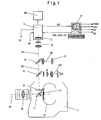
- FIG. 1 schematically illustrated optical system of a motion picture camera 1 with a camera assist device 2, 3 shows a taking lens 10, through which a recording beam S1 enters the motion picture camera 1 and strikes a rotating mirror aperture 11.
- the rotating mirror aperture 11 is usually composed of a semicircular mirror surface with a circumferential angle of usually 180 ° and a coaxial with the mirror surface arranged Aperture, which is adjustable relative to the mirror surface, so that aperture angle of 0 ° to 180 ° of the rotating mirror aperture 11 can be adjusted ,
- the rotating mirror aperture 11 of the receiving beam path S1 Depending on the angular position of the rotating mirror aperture 11 of the receiving beam path S1 hits the opening sector (bright sector) of the rotating mirror aperture 11 and passes through an image window 12 on a run in a film channel motion picture film 13.
- the image window 12 through the mirror surface of covered by the rotating mirror aperture 11 and the recording beam path S1 deflected to a ground glass or fiber plate 14, from where the receiving beam path S1 passes through a first beam splitter 15, of the receiving beam path S1 splits a viewfinder beam S3 into an eyepiece 16, through which the cameraman can view the image on the ground glass or fiber plate 14.
- the beam part S2 of the recording beam path S1 passing through the first beam splitter 15 possibly still reaches a second beam splitter 17, which splits the beam part S2 into a light meter beam path S5 for a light meter 18 and an assist beam path S4.
- the assist beam path S4 passes through an assist optics 19 to the camera assist device with an image sensor 2, which converts the optical image into image signals, and with an assist electronics 3, which generates digital signals from the image signals and the assists signals AS and possibly other control signals and data issues a personal computer 4 and receives control and data signals ASS, CS from the personal computer 4.
- the assist electronics 3 are further supplied with a mode select signal MS from the personal computer 4, which specifies a desired exposure mode, and a diaphragm index signal BI from the camera, which corresponds to the respective exposure conditions of the assist beam path S4 and thus the exposure conditions on the image sensor 2. Furthermore, the assist electronics 3 outputs camera control signals CC to the control electronics of the motion picture camera 1.
- the assist electronics 3 offers according to the Fig. 2 and 5 the possibility of connecting a monitor 35 on which the assist images composed of the digital assistance signals can be viewed directly on the motion picture camera.
- the personal computer 4 has, in addition to an input keyboard, an internal or external memory and a monitor, as well as output ports for outputting a CVBS, Y / C and DV (Digital Video) signal and a signal BD containing image data.
- the composite color, picture, blanking and sync signal FBAS is created by combining the luminance and chrominance signals.
- the Y / C signal corresponds to the two portions of the luminance Y and chrominance C of the entire color video signal transmitted separately on separate lines.
- the DV signal is a digital recording format, such as in recent times with consumer video recorders or Consumer camcorders is used. It can be recorded on devices that have corresponding inputs.
- FIG. 2 Block diagram shown shows the functional structure of the assist 3 and the image processing part of the personal computer. 4
- the camera assist device usually arranged in the camera head of the motion picture camera contains the image sensor 2, to which the assist beam path S4 according to FIG Fig. 1
- the output of the image sensor 2 is connected to an image processing device 32, which calculates a digital, color image from the output signals of the image sensor 2.
- the output of the image processing device is connected to an image compression device 33, which performs data compression in order to minimize the amount of data to be transmitted to the personal computer 4.
- the data compressed by the image compression means 33 are transmitted in a computer-usual format as a series of frames to the personal computer 4.
- a control device 30 establishes a connection between the camera control and the camera electronics 3 and outputs the input in an input field for operating settings 46 of the personal computer 4 specifications on the signal gain, the color setting, possibly settings of the motion picture camera 1, etc. to the image sensor. 2 and the image processing device 32, which receives them as control signals ASS and CS from the personal computer 4 via the line driver 34.
- An aperture index signal processing 31 is input side with the aperture index signal BI, which represents the exposure cycle of the motion picture camera 1, and a mode select signal MS applied by the PC, which specifies the respectively desired exposure mode.
- the aperture index signal conditioning 31 with a processed aperture index signal controls the timing of the image sensor 2 and the integration time TI as a function of the exposure cycle of the motion picture camera 1.
- a signal output is provided on the image data, preferably in VGA or XVGA format, onto a corresponding monitor 35, preferably a flat screen.
- the image processing part of the personal computer 4 includes an image memory unit 41 in which the digital assist signals AS transmitted via the line drivers 34 of the assist electronics 3 are stored as a series of frames in a computer-usual format.
- the image storage unit 41 may consist, for example, of the hard disk of the personal computer 4.
- the output of the image storage unit 41 is connected to an image processing device 42 in which the still compressed data of the series of individual images are decompressed and processed.
- An output of the rendering device 42 is connected to a graphics card 43 which converts the series of frames into a graphical representation for display on a monitor 44 of the personal computer 4.
- the display of images on the monitor of the PC is not necessarily dependent on the motion picture camera. Usually, the display is made from here in the frequency specified by the graphics card.
- a timing controller 40 controls the image processing device 42 so that, for example, the series of individual assist images currently output by the assisting electronics 3 with the digital assist signals AS are processed in time with the timing of the motion picture camera and controlled for direct viewing on the monitor 44.
- Another output of the image processing device 42 is connected to an image converter 45, which outputs a composite video signal, Y / C signal, DV signals and image data to further display devices and / or video memory devices or video recorder.
- a specification on the PC determines how different film speeds should be used. In a first software mode the images are always transferred to the video systems as in real recording time, in a second mode the images are always related to the film exposure time of the motion picture camera (screen time).
- the camera assist device accordingly produces 15 electronic (assist) frames per second.
- 15 electronic frames become 50 fields.
- the first electronic assist image becomes three assisted fields
- the second electronic image becomes three assisted fields
- the third electronic image becomes four assisted fields.
- the video frequency specifies a specific time frame.
- the electronic assist images are repeated as assisted frames until a new electronic assist image is available.
- assist frames are skipped accordingly.
- the second mode is based on the assumption that the images are recorded at 15 frames per second with the motion picture camera, but in the playback with z. 24 frames per second, ie with a time lapse of 24/15.
- the 15 pictures would be shown in the cinema in 15/24 seconds, ie 0.625 seconds. This corresponds to 31.25 video fields.
- 60 electronic pictures become 125 assisted fields.
- the first electronic image becomes two fields
- the second electronic image becomes two fields, and so on, up to the twelfth electronic image, which becomes three fields.
- the personal computer 4 contains an input field 46 for operating settings, which outputs the control signals ASS and CS via the line driver 34 to the control device 30 of the assist electronics 3 for specifying the gain, color setting and the exposure mode and optionally of settings of the motion picture camera.
- the input via the input field 46 of the personal computer 4 input control signals are processed and delivered as control signals VC to the image sensor 2 and the image processing device 32 or provided via a corresponding interface as camera control signals CC of the motion picture camera available.
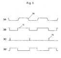
- the incident on the image sensor 2 Assist beam path S4 is converted into electronic image signals ( Fig. 3A and 4A ) and controlled by the controller 30 and the aperture index signal conditioning 31 to the image processing device 32.
- the diaphragm index signal processing acted upon by the diaphragm index signals BI 31 steepens the received aperture index signals via a Schmitt trigger and performs a phase shift of the received aperture index signals BI. This results in the time during which the assist beam path S4 according to Fig. 1 on the image sensor 2 reaching light from the image sensor 2 is integrated, depending on the aperture index signals BI and thus of the existing in the assist beam S4 light and the selected exposure mode.
- a first adjustable by means of the mode select signal MS exposure mode the reaching of the image sensor 2 light from a dark phase over the period of light phase, in which in the Assiststtahlengang S4 light is present until the next dark phase in the again no light in the assist beam S4 is present, according to Fig. 3B integrated.
- This first exposure mode leads to maximum bright assist images.
- the time at which the integration of the light is terminated by the image sensor 2 and then immediately started again irrelevant, as long as this time is in the dark phase of the assist beam path S4 and thus ensures that no unwanted light of a blind passage on the image sensor. 2 arrives.
- the area of the end of integration can be placed in the middle of the dark phase of the assist beam path S4, which is not mandatory for the function in the first exposure mode.
- the image sensor 2 in this mode will almost always be photosensitive. Only for a short time, the reading of the image sensor 2 is started according to a transfer signal TS. After the information has been read out in the image sensor, it becomes photosensitive again.
- a in Fig. 3C represented signal read out the photosensitive layer of the image sensor 2.
- the start of the read-out according to the transfer signal TS can be done immediately after the end of the by the in Fig. 3B illustrated signal-controlled integration of the light begin.
- Fig. 3D shows the output from the image sensor 2 to the image processing device 32 signal of the photosensitive layer of the image sensor 2. It corresponds to the time in which an electronic image is read out of the sensor.
- the image sensor 2 After the end of the readout of the photosensitive layer of the image sensor 2, the image sensor 2 is deleted or is already deleted depending on the design of the image sensor 2. Subsequently, a new integration of the incident light in the assist beam S4 light by the image sensor 2 begin.
- the output signals of the image sensor 2 are emitted as a function of the exposure cycle of the motion picture camera 1 from the image sensor 2 to the image processing device 32, where from the output signals of the image sensor 2, a digital, color correct image is calculated.
- the color mask of the chip is decoded, whereas in the case of image sensors with a plurality of chips, the images are combined in a manner known per se.
- the digital images are available in computer-usual formats as a series of individual images.
- the individual digital assist images computed by the rendering device 32 are compressed in the image compression 33 using a data compression method in order to minimize the amount of data to be transmitted for the individual digital assist images.
- the compressed image data is transmitted via line driver 34 to the personal computer 4 depending on the timing of the motion picture camera 1.
- the compressed image data is stored, for example, on the hard disk of the personal computer 4 and decompressed and processed in the image processing device 42.
- the graphics card 43 Via the graphics card 43, the decompressed and graphically processed data on the monitor 44 of the personal computer. 4 displayed.
- the decompression and conditioning of the image data as well as the conversion in the graphics card 43 is controlled by the timing controller 40.
- This timing generator is not necessarily coupled to the frequency of the transmitted assist images.
- the transmitted digital assist images which correspond to the individual film images, can thus be reproduced on the monitor 44 at different speeds, so that, for example, the effect of a special recording effect, such as a slow motion or a time-lapse, can be realistically simulated.
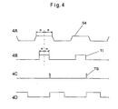
- the light-sensitive layer of the image sensor 2 is exposed to a significantly shorter exposure time, the exposure time being determined by the respective desired or set exposure time. This will usually be the exposure time of the motion picture film in the motion picture camera 1.
- the camera assist device can follow this setting of the exposure time of the motion picture film 13 and thus an assessment of this Real effect.
- Fig. 4A shows the sequence of light occurring in Assiststrahlengang S4 light. Subsequently, as described, the exposure time TI effective for the image sensor 2 is determined after a phase shift. The exposure time is usually shorter than easily in the assist beam S4 is present.
- the further waveform in the second exposure mode corresponds to the above with reference to the Fig. 3 described course of the first exposure mode.
- FIG. 5 Block diagram shown shows the functional structure of an advantageous development of the assist electronics 3 and the image processing part of the personal computer 4, all in the Fig. 2 illustrated components in this development perform the same function and are therefore provided with the same reference numerals and are used in parallel to the Assistzweig described above, so that a re-description is omitted here.
- a signal path branches off to a memory unit 36, which consists of an amplifier, an A / D Converter, an image memory and a D / A converter consists.
- the signals of the image sensor 2 are output from the image sensor 2 controlled by the light / dark phases in the assist beam path S4, amplified and converted into digital assist signals.
- These digital assist signals are read into the image memory, still in dependence on the light / dark phases in the assist beam path S4.
- the digital assist signals are read out with the frequency of the desired system, ie with 50 frames per second in PAL systems and 60 full frames per second in an NTSC system.
- the digital assist signals are converted back to analog signals via a D / A converter and then converted to regular video signals by video circuitry known from video cameras.
- the video circuit together with an image inserter, through which additional data can be faded into the video image, designated by the reference numeral 37.
- the video signals still pass through an output stage 38 in order to use common interfaces, for. B. a 75 ohm BNC output for CVBS signal can be used. These outputs, can also be diverted again for a small video monitor 39, it is not important which of the output signals is used.
- the additional video monitor 39 in parallel to the output for the monitor 35 has the advantage that in the described embodiment, both pure video monitors and VGA monitors can be connected.
- the combination of the known embodiment with analog video outputs and the variable transmission speed digital signal variant according to the invention offers the user the possibility of being able to display and record scenes in which no speed effects occur without the additional personal computer 4.
- the personal computer 4 is thus only connected if it because Speed effects or the better quality of digital images is necessary.
- Motion picture camera 2 Opto-electronic converter 3 Assist electronics 4 Personal computer 5 Fire-Wire Interface 10 taking lens 11 rotating mirror aperture 12 picture window 13 Motion picture film 14 Ground glass or fiber board 15 First beam splitter 16 eyepiece 17 second beam splitter 18 light meter 19 Assist optics 30 control device 31 Aperture index signal conditioning 32 Renderer 33 Image compression device 34 line driver 35 monitor 36 storage unit 37 Video circuit and image inserter 38 output stage 39 video monitor 40 timing control 41 Image storage unit 42 Renderer 43 graphic card 44 monitor 45 Image conversion device S1 Recording beam path S2 beamlet S3 Finder beam path S4 Assist beam path S5 Exposure meter beam path ABI processed aperture index signal BD Image data containing signal BI Aperture index signal CC Camera control signals AS Assist control signal DV Digital video signal composite Color, picture, blanking and synchronizing signal VC control signal AS Digital assists signal ASS Assist-control signal Y / C Luminance and chrominance signal
Abstract
Description
Die Erfindung betrifft ein Verfahren zum Verarbeiten von aus einem Filmaufnahmestrahlengang einer Laufbildkamera abgezweigten Filmbildern gemäß dem Oberbegriff des Anspruchs 1 sowie eine Vorrichtung zur Durchführung des Verfahrens.The invention relates to a method for processing film images branched off from a film recording beam path of a motion picture camera according to the preamble of
Der
Aus der
Aus der
Zu diesem Zweck wird ein Teil des Aufnahmestrahlengangs der Laufbildkamera in einen Videostrahlengang abgezweigt und einem Videobildsensor oder einer Videokamera zugeleitet. Dabei entwirft das Aufnahmeobjektiv der Laufbildkamera ein Bild in der Bild ebene des intermittierend beispielsweise mit einer Filmtransportgeschwindigkeit von 24 Bildern pro Sekunde bewegten Laufbildfilmes, wenn eine im Aufnahmestrahlengang der Laufbildkamera hinter dem Aufnahmeobjektiv angeordnete rotierende Spiegelblende den Aufnahmestrahlengang während der Belichtung eines Filmbildes freigibt. In der Zeit, in der der Laufbildfilm um eine Filmbildteilung weiter transportiert wird, verdeckt die bewegliche Spielgelblende den Aufnahmestrahlengang zur Bildebene und lenkt das Filmbild auf die Ebene einer Mattscheibe oder Faserplatte, von der das dort entstehende Bild über eine Videooptik auf einem Videobildsensor abgebildet wird.For this purpose, a part of the recording beam path of the motion picture camera is branched off into a video beam path and fed to a video image sensor or a video camera. The shooting lens of the motion picture camera designs a picture in the picture level of the motion picture film intermittently moving, for example, with a film transport speed of 24 frames per second, when a rotating mirror aperture arranged in the recording beam path of the motion picture camera behind the photographing lens releases the recording beam path during the exposure of a film frame. During the time in which the motion picture film is further transported by a film image division, the movable playing glare obscures the recording beam path to the image plane and directs the film image onto the plane of a ground glass or fiber plate, from which the resulting image is imaged via video optics on a video image sensor.
Der Videobildsensor integriert das auf seine lichtempfindliche Schicht fallende Licht des Videostrahlengangs. Die integrierten Signale werden periodisch aus dem Videobildsensor ausgelesen und als Videoausgangssignale auf einem Videomonitor dargestellt oder auf einem geeigneten Speichermedium gespeichert.The video image sensor integrates the light falling on its photosensitive layer of the video beam path. The integrated signals are periodically read from the video image sensor and displayed as video output signals on a video monitor or stored on a suitable storage medium.
Zwischen der Mattscheibe oder Faserplatte und der Videooptik befindet sich mindestens ein weiterer Strahlenteiler, der das Bild der Mattscheibe oder Faserplatte zu einem Okular abzweigt, über das ein Kameramann das Filmbild auf der Mattscheibe betrachten kann.Between the ground glass or fiber plate and the video optics, there is at least one further beam splitter, which branches off the image of the ground glass or fiber plate to an eyepiece, through which a cameraman can view the film image on the ground glass.
Infolge der periodischen Unterbrechung des Aufnahmestrahlengangs der Laufbildkamera in Abhängigkeit von der Bildaufnahmefrequenz der Laufbildkamera trifft somit während der Filmbelichtung kein Licht auf den Videobildsensor, was von Sonderfällen abgesehen zu einem Bildflimmern des mit dem Videoausgangssignal des Videobildsensors erzeugbaren Videobildes führt. Dieses Bildflimmern wird noch dadurch verstärkt, dass die zur Aufladung eines Bildpunktes des Ladungsbildes des Videobildsensors wirksame Zeit zwischen dem letzten löschenden Auslesen und dem nächsten löschenden Auslesen des Ladungsbildes des Videobildsensors durch von Bild zu Bild wechselnde Zeitintervalle verkürzt wird, während denen der Videostrahlengang zum Videobildsensor unterbrochen ist.As a result of the periodic interruption of the recording beam path of the motion picture camera depending on the image recording frequency of the motion picture camera thus encounters no light on the video image sensor during film exposure, which leads except for special cases to a flickering of the video output signal of the video image sensor producible video image. This image flickering is further enhanced by the fact that the time effective for charging a pixel of the charge image of the video image sensor between the last deleting readout and the next deleting readout of the charge image of the video image sensor is shortened by image-to-image time intervals during which the video beam path to the video image sensor is interrupted is.
Dadurch ist die jeweilige Zeitspanne wirksamer Belichtung für einen Bildpunkt des Ladungsbildes des Videobildsensors zwischen einem löschenden Auslesen des Ladungsbildes zum Erzeugen des Videoausgangssignals und dem nächsten löschenden Auslesen des Ladungsbildes zum Erzeugen des nächsten Videoausgangssignales von Bild zu Bild unterschiedlich lang, da die übliche Bildaufnahmefrequenz einer Laufbildkamera nur in Ausnahmefällen mit der Videofrequenz der Videoeinrichtung übereinstimmt. So beträgt beispielsweise die Bildaufnahmefrequenz einer Laufbildkamera üblicherweise 24 Bilder pro Sekunde, während die Videofrequenz einer Videoeinrichtung bei einem PAL-System 50 Bilder pro Sekunde und bei einem NTSC-System bei 60 Bildern pro Sekunde beträgt. Dieses Bildflimmern wirkt sich in einer Hell/Dunkel-Änderung eines Videobildes oder Videohalbbildes zum jeweils nächsten aus, was die Videobildbetrachtung erschwert bzw. unmöglich macht.Thereby, the respective period of effective exposure for one pixel of the charge image of the video image sensor between erasure readout of the charge image for generating the video output signal and the next erasive readout of the charge image for generating the next video output signal is different from image to image, since the usual image acquisition frequency of a motion picture camera only in exceptional cases coincides with the video frequency of the video device. For example, the image-taking frequency of a motion picture camera is usually 24 frames per second, while the video frequency of a video device is 50 frames per second in a PAL system and 60 frames per second in an NTSC system. This flickering affects the lightness / darkness of a video image or video field to the next, which makes the video image viewing difficult or impossible.
Zur Beseitigung bzw. Reduzierung dieses Bildflimmems ist es aus der
Unabhängig von der Filmtransportgeschwindigkeit bzw. Bildaufnahmefrequenz der Laufbildkamera entspricht somit das Videoausgangssignal der bekannten Videoeinrichtung der normgerechten Videobildfrequenz und wird am Ausgang der Videoeinrichtung in Form eines FBAS-Signals (Farbart-, Bildinhalt-, Austast- und Synchronisier-Signal) zur Anzeige auf einem Videomonitor oder zur Videosignalspeicherung zu Verfügung gestellt.Regardless of the film transport speed or image recording frequency of the motion picture camera thus corresponds to the video output signal of the known video device of the standard video frame rate and at the output of the video device in the form of a composite video signal (Farbart-, Bildinhalt-, blanking and synchronizing signal) for display on a video monitor or for video signal storage.
Ein wesentlicher Nachteil dieses starren Video Assist Systems besteht darin, dass durch die Erzeugung und Abgabe normgerechter Videobilder auf die Besonderheiten eines Laufbildfilms nicht eingegangen wird. Dies führt zu Problemen bei der Nachbearbeitung des Laufbildfilmes und zum Verzicht auf besondere Effekte, die mit dem Laufbildfilm erzeugt, aber mit der Videoeinrichtung aus den folgenden Gründen nicht dargestellt werden können.A major disadvantage of this rigid video assist system is that the production and output of standards-compliant video images on the peculiarities of a motion picture film is not discussed. This leads to problems in the post-processing of the motion picture film and to avoid special effects that are generated with the motion picture film, but with the video device for the following reasons can not be displayed.
Da die Standard-Bildaufnahmefrequenz einer Laufbildkamera 24 Bilder/s beträgt, sind für die Nachbearbeitung eines Laufbildfilmes und insbesondere für den Filmschnitt bereits Schnittcomputer bekannt, die mit einer zeitlichen Auflösung von 24 Bildern pro Sekunde arbeiten, so dass bei einem Einsatz einer Videoaufzeichnung zur Erleichterung der Nachbearbeitung des Laufbildfilmes zunächst das Videosignal in Abhängigkeit vom jeweiligen System (PAL oder NTSC) mit einer Videofrequenz von 25 oder 30 Videobildern pro Sekunde auf die Bildaufnahmefrequenz der Laufbildkamera von 24 Bildern pro Sekunde konvertiert werden muß.Since the standard image pickup frequency of a motion picture camera is 24 fps, for the post-processing of a motion picture film, and in particular for the film cut editing computer are already known, which operate with a temporal resolution of 24 frames per second, so that when using a video recording to facilitate the Post-processing of the motion picture film first the video signal depending on the respective System (PAL or NTSC) with a video frequency of 25 or 30 video frames per second to the image recording frequency of the motion picture camera of 24 frames per second to be converted.
Des weiteren ermöglicht die starre, normgerechte Videobildfrequenz nicht die Wiedergabe von Zeitlupen- oder Zeitraffer-Effekten eines Laufbildfilmes, der mit einer von der Standard-Bildaufnahmefrequenz abweichenden Bildaufnahmefrequenz belichtet wurde. Dabei wird die Laufbildkamera zur Erzeugung eines Zeitlupeneffektes mit einer höheren Transportgeschwindigkeit oder zur Erzeugung eines Zeitraffereffektes mit einer niedrigeren Filmtransportgeschwindigkeit als der Standard-Filmtransportgeschwindigkeit bzw. Bildaufnahmefrequenz bewegt. Wird der Laufbildfilm bei der Projektion wieder mit der normalen Standard-Bildaufnahmefrequenz von 24 Bildern pro Sekunde bewegt, so werden die entsprechenden Zeitlupen- und Zeitraffer-Effekte realisiert. Diese Effekte können wegen der starren, normgerechten Videobildfrequenz nur unzureichend dargestellt werden.Furthermore, the rigid, standard video frame rate does not allow for the reproduction of slow motion or fast motion effects of a motion picture film which has been exposed at an image acquisition frequency other than the standard frame rate. In this case, the motion picture camera is moved to produce a slow-motion effect with a higher transport speed or to generate a time-lapse effect with a lower film transport speed than the standard film transport speed or image recording frequency. If the motion picture film is moved again at the normal standard image recording frequency of 24 images per second during projection, the corresponding slow-motion and time-lapse effects are realized. These effects can only be displayed inadequately because of the rigid, standard-compliant video picture frequency.
Es sind zwar Verfahren bekannt, diese Effekte elektronisch nachzuvollziehen, aber alle Ansätze führen zu einer unsauberen, holpernden Bewegungsauflösung.Although methods are known to electronically understand these effects, but all approaches lead to an unclean, jarring motion resolution.
Weiterhin begründet die Tatsache, dass nur zur Hälfte eines gesamten Filmbildzyklus Licht im Sucher und somit auf dem Videosensor vorhanden ist, eine Halbbildauflösung im Videoausgangssignal. Üblicherweise wird immer ein Odd- oder ein Even-Halbbild richtig belichtet, das andere Halbbild wird zu der Zeit belichtet, in der der Sensor kein Licht erhält. Um aber ein Videobild zu erhalten, das eben nicht die störenden Hell/Dunkel Folgen zeigt, wird der Inhalt der unbelichteten Halbbilder durch den Inhalt der vorher belichteten Halbbilder ersetzt. Dabei verliert man zwangsläufig die Information, die bei nicht unterbrochener Belichtung im zweiten Halbbild stehen würde.Furthermore, the fact that only half of a full motion picture cycle has light in the viewfinder and thus on the video sensor establishes a field resolution in the video output signal. Usually one odd or even field is always exposed correctly, the other field is exposed at the time the sensor is not receiving light. But to get a video image that just does not show the disturbing light / dark consequences, the content of the unexposed fields is replaced by the contents of the previously exposed fields. It inevitably loses the information that would be in the second field with uninterrupted exposure.
Aufgabe der vorliegenden Erfindung ist es, ein Verfahren zum Verarbeiten von aus einem Filmaufnahmestrahlengang einer Laufbildkamera abgezweigten Filmbildern anzugeben, das an die Besonderheiten einer Laufbildkamera angepasst ist und insbesondere eine einwandfreie Darstellung von mit einem Laufbildfilm erzeugten Spezialeffekten wie Zeitlupen- und Zeitraffer-Aufnahmen gewährleistet.The object of the present invention is to specify a method for processing film images branched off from a film recording beam path of a motion picture camera, which is adapted to the special features of a motion picture camera and, in particular, guarantees a flawless presentation of special effects produced by a motion picture film, such as slow-motion and time-lapse recordings.
Diese Aufgabe wird erfindungsgemäß durch ein Verfahren mit den Merkmalen des Anspruchs 1 gelöst.This object is achieved by a method having the features of
Die erfindungsgemäße Lösung gewährleistet ein an die Besonderheiten einer Laufbildkamera angepasstes Verarbeiten von aus einem Filmaufnahmestrahlengang einer Laufbildkamera abgezweigten Filmbildern und ermöglicht insbesondere die einwandfreie Darstellung von mit einem Laufbildfilm erzeugten Spezialeffekten wie Zeitlupen- und Zeitraffer-Aufnahmen, insbesondere unter Beibehaltung einer Vollbildauflösung.The solution according to the invention ensures processing of film images derived from a film recording beam path of a motion picture camera adapted to the particular features of a motion picture camera, and in particular enables the flawless presentation of special effects produced by a motion picture film, such as slow-motion and time-lapse recordings, in particular while maintaining a full-screen resolution.
Die erfindungsgemäße Lösung geht von der Überlegung aus, abweichend von den bekannten Verfahren zur normgerechten Aufbereitung von Videosignalen zur flimmerfreien Darstellung von Videobildern oder Video-Halbbildern parallel zu jedem Filmbild ein elektronisches, vorzugsweise digitales Assistbild auszugeben. Da dieses Verfahren mit den Standards für Videobildsignale bricht, muss das dieses Verfahren realisierende Format ein spezielles, vorzugsweise ein digitales Format sein. Da dieses Format aber nicht auf handelsüblichen Videorecordern oder Videomonitoren dargestellt werden kann, wird das digitale Assistsignal an eine Datenverarbeitungseinrichtung abgegeben, in der bzw. von der das elektronische Assistbild auf einem Monitor dargestellt oder gespeichert wird. Dadurch wird es möglich, elektronische Assistbilder zum Beispiel mit 35 Bildern pro Sekunde, d.h. als leichte Zeitlupe an die Datenverarbeitungseinrichtung zu übertragen. Dort werden die Assistbilder zunächst in Echtzeit, also genau wie die von der Laufbildkamera aufgenommene Szene, dargestellt und/oder aufgezeichnet. Weiterhin kann die gespeicherte Szene dann erneut entweder wieder in Echtzeit oder unter der Annahme einer Betrachtungsgeschwindigkeit von beispielsweise 24 Bildern pro Sekunde je nach Aufnahmegeschwindigkeit als Zeitlupe oder Zeitraffer wiedergegeben werden.The solution according to the invention is based on the consideration, in contrast to the known methods for standard-compliant preparation of video signals for the flicker-free display of video images or video fields parallel to each film image to output an electronic, preferably digital Assistbild. Since this method breaks with the standards for video picture signals, the format implementing this method must be a special, preferably a digital format. However, since this format can not be displayed on commercially available video recorders or video monitors, the digital assistsignal is delivered to a data processing device in which or from the electronic assisted image is displayed or stored on a monitor. This makes it possible to use electronic assist images, for example at 35 frames per second, i. as a slight slow motion to the data processing device to transfer. There, the assist images are first displayed and / or recorded in real time, that is to say exactly as the scene recorded by the motion picture camera. Furthermore, the stored scene can then be reproduced again either in real time or assuming a viewing speed of, for example, 24 frames per second depending on the recording speed as slow motion or fast motion.
Dementsprechend werden bei dem erfindungsgemässen Verfahren zum Verarbeiten von aus einem Filmaufnahmestrahlengang einer Laufbildkamera abgezweigten Filmbildern digitale Assistsignale mit einer mit der Bildaufnahmefrequenz der Laufbildkamera übereinstimmenden Bildfrequenz an eine Datenverarbeitungseinrichtung abgegeben, die aus den digitalen Assistsignalen gebildete Assistbilder mit der Bildaufnahmefrequenz der Laufbildkamera verarbeitet. Die Datenverarbeitungseinrichtung gibt die digitalen Assistsignale zur Anzeige der Assistbilder mit einer Assistbildfrequenz oder der Bildaufnahmefrequenz der Laufbildkamera an eine digitale Speichereinrichtung oder mit einer normierten Bildfrequenz, beispielsweise 24 Bildern pro Sekunde, an einen Monitor ab.Accordingly, in the method according to the invention for processing film images branched from a film recording beam path of a motion picture camera, digital assist signals with a frame frequency matching the image recording frequency of the motion picture camera are delivered to a data processing device which processes assist images formed from the digital assist signals with the image recording frequency of the motion picture camera. The data processing device outputs the digital assists signals for displaying the assist images with an assist image frequency or the image acquisition frequency the motion picture camera to a digital storage device or with a normalized frame rate, for example 24 frames per second, to a monitor.
Optional können die Assistbilder aus der Datenverarbeitungseinrichtung heraus als digitale Videosignale, FBAS- oder Y/C-Signale an Anzeige- oder digitale oder analoge Speichereinrichtungen weitergegeben werden.Optionally, the assist images may be passed out of the data processing device as digital video signals, CVBS or Y / C signals to display or digital or analog storage devices.
Eine vorteilhafte Variante des erfindungsgemäßen Verfahrens ist durch einen separaten, einem bisher bekannten Video-Assist entsprechenden Videozweig gekennzeichnet, in dem übliche Videosignale mit einer der Videonorm entsprechenden Videosignalfrequenz über eine genormte Schnittstelle an übliche Videogeräte z. B. Videomonitore und Videorekorder gesendet werden. In einem zweiten Signalpfad können die elektronischen Bildsignale bzw. digitalen Assistsignale mit einer mit der Bildaufnahmefrequenz der Laufbildkamera übereinstimmenden Bildfrequenz an die Datenverarbeitungseinrichtung abgegeben werden.An advantageous variant of the method according to the invention is characterized by a separate, a previously known video assist video branch corresponding in the usual video signals with a video standard corresponding video signal frequency via a standard interface to conventional video equipment such. B. video monitors and video recorders are sent. In a second signal path, the electronic image signals or digital assistsignals can be delivered to the data processing device at a frame rate matching the image recording frequency of the motion picture camera.
In dieser Ausgestaltung der Erfindung wird aus dem ersten Signalpfad ein FBAS, Y/C und DV-Signal mit 25 oder 30 vollen Assistbildem pro Sekunde über übliche Schnittstellen ausgegeben, während in dem zweiten Signalpfad ein elektronisches Assistbild pro Filmbild an die Datenverarbeitungseinrichtung ausgegeben wird, so dass sowohl ein flimmerfreier Standardbetrieb als auch eine auf die besonderen Eigenschaften und Möglichkeiten der Laufbildkamera abgestellte Betriebsart verwendet werden kann.In this embodiment of the invention, a CVBS, Y / C and DV signal with 25 or 30 full Assistbildem per second output via conventional interfaces from the first signal path, while in the second signal path, an electronic assist image per film image is output to the data processing device, so that both a flicker-free standard operation as well as a parked on the special features and possibilities of the motion picture camera operating mode can be used.
Wenn die Laufbildkamera mit einer Geschwindigkeit bzw. mit einer Bildaufnahmefrequenz läuft, die höher ist als die über die Schnittstelle zu übertragende Datenrate bzw. höher als die mit dem optoelektronischen Wandler realisierbare Geschwindigkeit, d.h. mit einer Geschwindigkeit von mehr als etwa 50 bis 60 Bildern pro Sekunde, so wird nur jedes zweite elektronische Assistbild zur Datenverarbeitungseinrichtung übertragen. In diesem Modus wird optional das Licht von zwei Durchgängen der Spiegelblende integriert. Dadurch erreicht man eine höhere Belichtung des optoelektronischen Wandlers. Da dieser Modus allerdings zwei Filmbilder zu einem elektronischen Assistbild zusammenfügt, ist dieser Modus abschaltbar, um die Eindeutigkeit der Zuordnung der Bilder zu erhalten.When the motion picture camera is running at a speed or an image recording frequency which is higher than the data rate to be transmitted via the interface or higher than the speed which can be achieved with the optoelectronic converter, ie at a speed of more than approximately 50 to 60 images per second Thus, only every second electronic assist image is transmitted to the data processing device. In this mode, the light of two passes of the mirror aperture is optionally integrated. This achieves a higher exposure of the optoelectronic transducer. However, since this mode merges two film images into an electronic assist image, this mode can be switched off in order to obtain unambiguous assignment of the images.
Über einen Rückkanal auf dieser Schnittstelle können von der Datenverarbeitungseinrichtung Kamera- und Assiststeuerinformationen zur Laufbildkamera bzw. einer in die Laufbildkamera integrierten bzw. mit dieser verbundenen Kamera-Assisteinrichtung gesandt werden, während umgekehrt auf einem Meta-Datenkanal zusätzliche Aufnahme-, Steuer- oder Statussignale bzw. Daten wie beispielsweise Kamera-Status-Informationen zurück zur Datenverarbeitungseinrichtung geschickt werden können, so dass dadurch beispielsweise ein Modus entsteht, der die Assistbilder in der Datenverarbeitungseinrichtung automatisch aufzeichnet, wenn die Laufbildkamera läuft.Via a return channel on this interface, camera and assist control information for the motion picture camera or a camera assist device integrated in the motion picture camera can be sent by the data processing device, while conversely on a meta data channel additional recording, control or status signals or Data such as camera status information can be sent back to the data processing device, so that, for example, a mode is created which automatically records the assist images in the data processing device when the motion picture camera is running.
Weiterhin kann eine Einblendung von auswählbaren Steuer-, Status- und/oder Aufnahmedaten in das Bild für zusätzliche Informationen beispielsweise bei der Nachbearbeitung eines Laufbildfilmes vorgesehen werden. Die Einblendung kann entweder dem Bildinhalt überlagert werden, so dass er auch beim Abspeichern der Informationen aus der Datenverarbeitungseinrichtung heraus auf klassischen Videosystemen erhalten bleibt, oder neben dem eigentliche Bildinhalt auf freien Bereichen eines Monitors angezeigt werden. Da die Metadaten parallel zu den eigentlichen Assistbildern in der Datenverarbeitungseinrichtung gespeichert werden, können sie innerhalb dieser Einheit immer wieder, auch außerhalb des eigentlichen Bildbereiches, angezeigt werden.Furthermore, an overlay of selectable control, status and / or recording data into the image can be provided for additional information, for example during the post-processing of a motion picture film. The overlay can either be superimposed on the image content, so that it also remains when saving the information from the data processing device out on classic video systems, or displayed next to the actual image content on free areas of a monitor. Since the metadata are stored parallel to the actual Assist images in the data processing device, they can be displayed within this unit again and again, even outside the actual image area.
Somit übernimmt die Datenverarbeitungseinrichtung die klar lesbare Einblendung wichtiger Daten in das Assistbild bzw. auf dem Assist-Monitor und kann die Daten als normgerechtes Videosignal z. B. an einen Videorecorder oder Videomonitor bzw. direkt per Dateikopierung, also nicht als Videosignal, an einen zur Nachbearbeitung des Laufbildfilmes vorgesehenen Schnittcomputer abgeben.Thus, the data processing device takes over the clearly legible display of important data in the Assist image or on the Assist monitor and can the data as standard-compliant video signal z. B. to a VCR or video monitor or directly by file copy, so do not deliver as a video signal to a provided for post-processing of the motion picture film editing computer.
Eine bevorzugte Ausführungsform des erfindungsgemäßen Verfahrens ist dadurch gekennzeichnet, dass die Lichtverhältnissen im Assiststrahlengang der Laufbildkamera repräsentiert werden durch entsprechende Blendenindexsignale, die über eine Blendenindex-Signalaufbereitung an den optoelektronischen Wandler abgegeben werden, der in Abhängigkeit von den aufbereiteten Blendenindexsignalen in einem ersten Belichtungsmodus die Lichtmenge im Assiststrahlengang von einer Dunkelphase des Assiststrahlengangs bis zur nächsten Dunkelphase integriert, wobei die integrierte Lichtmenge nach dem Ende der Integration von einer Bildaufbereitungseinrichtung ausgelesen wird.A preferred embodiment of the method according to the invention is characterized in that the light conditions in the assist beam path of the motion picture camera are represented by corresponding diaphragm index signals, which are output to the optoelectronic transducer via an aperture index signal conditioning, which in dependence on the processed diaphragm index signals in a first exposure mode, the amount of light in Assist beam path integrated from a dark phase of the assist beam path to the next dark phase, the integrated amount of light is read out after the end of the integration of an image processing device.
In einem zweiten Belichtungsmodus wird die Belichtungszeit des optoelektronischen Wandlers auf einen vorgebbaren Wert, vorzugsweise auf die Filmbelichtungszeit der Laufbildkamera eingestellt, die Lichtmenge des Assiststrahlengangs von einem Startwert in der Hellphase bis zu einem Endwert in dieser Hellphase integriert und die integrierten Lichtmenge nach dem Ende der Integration, die zeitlich dem vorgegebenen Wert entspricht, von der Bildaufbereitungseinrichtung ausgelesen. Dabei kann in einer bevorzugten Ausführungsform die Mitte der eingestellten Belichtungszeit des optoelektronischen Wandlers auf die Mitte der Hellphase im Assiststrahlengang eingestellt werden. Auch in diesem Modus ist bei einer Kameralaufgeschwindigkeit oberhalb der maximalen Frequenz des Assistsystems ein Zusammenfassen mehrerer Blendendurchgänge zu einem Assistbild vorgesehen.In a second exposure mode, the exposure time of the optoelectronic transducer is set to a predeterminable value, preferably the film exposure time of the motion picture camera, the amount of light of the assist beam path from a start value in the light phase to a final value integrated in this light phase and the integrated amount of light after the end of the integration , which corresponds in time to the predetermined value, read by the image processing device. In this case, in a preferred embodiment, the center of the set exposure time of the optoelectronic transducer can be set to the middle of the light phase in the assist beam path. Also in this mode, at a camera run-up speed above the maximum frequency of the assist system, a merger of multiple blend passes to an assist image is provided.
Nach der Bilderfassung und Abgabe der digitalen Assistsignale durch den bzw. die optoelektronischen Wandler wird das digitale Assistbild errechnet, wobei bei einem einzelnen optoelektronischen Wandler die Farbmaske des optoelektronischen Wandlers dekodiert und bei mehreren optoelektronischen Wandler die Bilder der optoelektronischen Wandler miteinander kombiniert werden. Anschließend werden die Bilddaten der digitalen Assistbilder an eine Bildkomprimierungseinrichtung abgegeben, die die Bilddaten der digitalen Assistbilder komprimiert und über Leitungstreiber in Abhängigkeit von der Bildaufnahmefrequenz der Laufbildkamera an die Datenverarbeitungseinrichtung abgibt, die die Bilddaten der digitalen Assistbilder speichert, dekomprimiert und zur Anzeige auf einem externen oder internen Monitor gesteuert von einer Timing-Steuerung aufbereitet.After image acquisition and delivery of the digital assistsignals by the optoelectronic transducer (s), the digital assist image is calculated, decoding the color mask of the optoelectronic transducer in a single optoelectronic transducer, and combining the images of the optoelectronic transducers in a plurality of optoelectronic transducers. Subsequently, the image data of the digital assist images are delivered to an image compression device which compresses the image data of the digital assist images and outputs via line driver depending on the image recording frequency of the motion picture camera to the data processing device, which stores the image data of the digital assist images, decompressed and displayed on an external or internal monitor controlled by a timing control.
Noch vor der Komprimierung der Bilddaten besteht die Möglichkeit, einen Datenpfad für einen Monitor direkt aus der Kamera-Assisteinrichtung der Laufbildkamera auszukoppeln. Als Monitor dient dabei ein üblicher Computer Monitor mit VGA bzw. XVGA Eingang.Even before the compression of the image data, it is possible to decouple a data path for a monitor directly from the camera assist device of the motion picture camera. The monitor is a conventional computer monitor with VGA or XVGA input.
Der Signal- und Datenaustausch zwischen der Kamera-Assisteinrichtung und der Datenverarbeitungseinrichtung erfolgt vorzugsweise binär codiert, insbesondere als PCM-Signal (Pulse Code Modulation), wobei die Signale und Daten kabelgebunden, über Lichtwellenleiter oder Glasfasern, mittels eines Trägerfrequenzsystems oder über eine Infrarotschnittstelle übertragen werden.The signal and data exchange between the camera assist device and the data processing device is preferably binary coded, in particular as a PCM signal (Pulse Code Modulation), wherein the signals and data are wired, transmitted via optical fibers or glass fibers, by means of a carrier frequency system or via an infrared interface ,
Eine Vorrichtung zur Durchführung des Verfahrens ist durch eine Kamera-Assisteinrichtung mit einem auf den Assiststrahlengang gerichteten Bildsensor und eine Datenverarbeitungseinrichtung gekennzeichnet, die die von der Kamera-Assisteinrichtung mit einer mit der Bildaufnahmefrequenz der Laufbildkamera übereinstimmenden Bildfrequenz abgegebenen digitalen Assistsignale empfängt und die aus den digitalen Assistsignalen zusammengestellte digitale Assistbilder mit der Bildaufnahmefrequenz der Laufbildkamera verarbeitet.A device for carrying out the method is characterized by a camera assist device with an image sensor directed towards the assist beam path and a data processing device which receives the digital assist signals output by the camera assist device at a frame rate matching the image recording frequency of the motion picture camera and those from the digital assist signals compiled digital assist images with the image recording frequency of the motion picture camera processed.
Vorzugsweise ist die Datenverarbeitungseinrichtung mit einer digitalen Speichereinrichtung und/oder einem Monitor verbunden und besteht aus einem Personal Computer (PC) auf dessen Monitor die elektronischen Bilder betrachtet werden können.Preferably, the data processing device is connected to a digital storage device and / or a monitor and consists of a personal computer (PC) on whose monitor the electronic images can be viewed.
Die Übertragung der elektronischen Bilder von der Assisteinrichtung zum Personal Computer kann insbesondere über eine Fire-Wire-Schnittstelle des Personal Computers erfolgen, so dass keine zusätzlichen Hardwareanforderungen für die Durchführung des erfindungsgemäßen Verfahrens zu erfüllen sind. Es sind aber speziell zur flexiblen Übertragung der elektronischen Bilder ohne fixe Bildfrequenzen ein eigenständiges Übertragungssysteme sinnvoll.The transmission of the electronic images from the assisting device to the personal computer can take place in particular via a fire-wire interface of the personal computer, so that no additional hardware requirements for carrying out the method according to the invention are to be fulfilled. However, it is especially useful for the flexible transmission of electronic images without fixed frame rates an independent transmission systems.
Als im Assiststrahlengang der Laufbildkamera angeordneter Bildsensor kann wahlweise ein CCD-Chip, ein C-MOS-Bildsensor oder eine Bildröhre eingesetzt werden, die insbesondere im Progressive-Scan-Betrieb arbeiten, obwohl der Einsatz eines Interlaced Chips ebenfalls grundsätzlich möglich ist.As arranged in the assist beam path of the motion picture camera image sensor can either a CCD chip, a C-MOS image sensor or a picture tube are used, which work especially in progressive scan mode, although the use of an interlaced chip is also possible in principle.
Eine weitere vorteilhafte Ausgestaltung ist durch ein Eingabefeld für Betriebseinstellungen gekennzeichnet, die über graphisch dargestellte Bedienelemente der Kamera-Assisteinrichtung ausgeführt werden. An dem Eingabefeld können beispielsweise Vorgaben über die Signalverstärkung, die Farbeinstellung, der Belichtungsmodus und ggf. Einstellungen der Laufbildkamera vorgenommen werden. Über eine Rückleitung zur Kamera-Assisteinrichtung der Laufbildkamera werden die Daten an eine Steuerung der Kamera-Assisteinrichtung abgegeben, von wo sie auf den Bildsensor bzw. die Bildaufbereitung wirken oder über eine entsprechende Schnittstelle als Kamera-Steuersignale der Laufbildkamera zur Verfügung gestellt werden.A further advantageous embodiment is characterized by an input field for operating settings, which are executed via graphically illustrated operating elements of the camera assist device. For example, specifications on the signal amplification, the color setting, the exposure mode and possibly the settings of the motion picture camera can be made on the input field. Via a return line to the camera assist device of the motion picture camera, the data are delivered to a controller of the camera assist device, from where they act on the image sensor or the image processing or are made available via a corresponding interface as camera control signals of the motion picture camera.
Anhand von in der Zeichnung dargestellten Ausführungsbeispielen soll der der Erfindung zugrundeliegende Gedanke näher erläutert werden. Es zeigen:
- Fig. 1
- eine schematische Darstellung des Strahlengangs einer Laufbildkamera mit ei- ner rotierenden Spiegelblende und einer Kamera-Assisteinrichtung;
- Fig. 2
- ein Blockschaltbild der Elektronik der Kamera-Assisteinrichtung und des bild- bearbeitenden Teils einer als Personal Computer ausgebildeten Datenver- arbeitungseinrichtung;
- Fig. 3
- eine zeitliche Darstellung der Signale der Kamera-Assisteinrichtung in einem ersten Belichtungsmodus;
- Fig. 4
- eine zeitliche Darstellung der Signale der Kamera-Assisteinrichtung in einem zweiten Belichtungsmodus und
- Fig. 5
- ein Blockschaltbild der Elektronik der Kamera-Assisteinrichtung mit einem se- paraten Videozweig und des bildbearbeitenden Teils eines Personal Com- puters.
- Fig. 1
- a schematic representation of the beam path of a motion picture camera with a rotating mirror aperture and a camera assist device;
- Fig. 2
- a block diagram of the electronics of the camera assist device and the image-processing part of a designed as a personal computer data processing device;
- Fig. 3
- a temporal representation of the signals of the camera assist device in a first exposure mode;
- Fig. 4
- a temporal representation of the signals of the camera assist device in a second exposure mode and
- Fig. 5
- a block diagram of the electronics of the camera assist device with a separate video branch and the image processing part of a personal computer.
Das in
Je nach Winkelstellung der rotierenden Spiegelblende 11 trifft der Aufnahmestrahlengang S1 auf den Öffnungssektor (Hellsektor) der rotierenden Spiegelblende 11 und gelangt durch ein Bildfenster 12 auf einen in einem Filmkanal geführten Laufbildfilm 13. Während des Transports des Laufbildfilms 13 wird das Bildfenster 12 durch die Spiegelfläche der rotierenden Spiegelblende 11 abgedeckt und der Aufnahmestrahlengang S1 auf eine Mattscheibe oder Faserplatte 14 abgelenkt, von wo aus der Aufnahmestrahlengang S1 durch einen ersten Strahlteiler 15 gelangt, der von dem Aufnahmestrahlengang S1 einen Sucherstrahlengang S3 in ein Okular 16 abspaltet, durch das der Kameramann das Bild auf der Mattscheibe oder Faserplatte 14 betrachten kann.Depending on the angular position of the
Der durch den ersten Strahlenteiler 15 gelangende Strahlenteil S2 des Aufnahmestrahlenganges S1 gelangt möglicherweise noch auf einen zweiten Strahlteiler 17, der den Strahlenteil S2 in einen Belichtungsmesser-Strahlengang S5 für einen Belichtungsmesser 18 und einen Assiststrahlengang S4 aufteilt.The beam part S2 of the recording beam path S1 passing through the
Der Assiststrahlengang S4 gelangt durch eine Assistoptik 19 zu der Kamera-Assisteinrichtung mit einem Bildsensor 2, der das optische Bild in Bildsignale umwandelt, und mit einer Assistelektronik 3, die aus den Bildsignalen digitale Signale erzeugt und die Assistsignale AS sowie gegebenenfalls weitere Steuersignale und Daten an einen Personal Computer 4 abgibt sowie Steuer- und Datensignale ASS, CS vom Personal Computer 4 empfängt.The assist beam path S4 passes through an
Der Assistelektronik 3 wird weiterhin ein Mode-Select-Signal MS vom Personal Computer 4 zugeführt, das einen gewünschten Belichtungsmodus vorgibt, sowie ein Blendenindexsignal BI von der Camera, das den jeweiligen Belichtungsverhältnissen des Assiststrahlenganges S4 und damit den Belichtungsverhältnissen auf dem Bildsensor 2 entspricht. Weiterhin gibt die Assistelektronik 3 Kamera-Steuersignale CC an die Steuerelektronik der Laufbildkamera 1 ab.The assist
Die Assistelektronik 3 bietet gemäß den
Der Personal Computer 4 weist neben einer Eingabetastatur einen internen oder externen Speicher und einen Monitor, sowie Ausgabeports zur Abgabe eines FBAS-, Y/C- und DV (Digitales Video)-Signals sowie eines Bilddaten enthaltenden Signals BD ab. Das zusammengesetzte Farb-, Bild-, Austast- und Synchronsignal FBAS entsteht durch die Zusammenführung von Luminanz- und Chrominanz-Signal. Das Y/C-Signal entspricht den beiden separat auf eigenen Leitungen übertragenen Anteilen der Luminanz Y und Chrominanz C des gesamten Farbvideosignals. Bei dem DV-Signal handelt es sich um ein digitales Aufzeichnungsformat, wie es in der letzten Zeit bei Consumer-Videorecordern oder Consumer-Camcordern verwendet wird. Es kann auf Geräten, die über entsprechende Eingänge verfügen, aufgezeichnet werden.The
Das in
Die üblicherweise im Kamerakopf der Laufbildkamera angeordnete Kamera-Assisteinrichtung enthält den Bildsensor 2, auf den der Assiststrahlengang S4 gemäß
Eine Steuereinrichtung 30 stellt eine Verbindung zwischen der Kamerasteuerung und der Kamera-Elektronik 3 her und gibt die in einem Eingabefeld für Betriebseinstellungen 46 des Personal Computers 4 eingegebenen Vorgaben über die Signalverstärkung, die Farbeinstellung, ggf. Einstellungen der Laufbildkamera 1 usw. an den Bildsensor 2 sowie die Bildaufbereitungseinrichtung 32 weiter, die sie als Steuersignale ASS und CS vom Personal Computer 4 über die Leitungstreiber 34 empfängt.A
Eine Blendenindex-Signalaufbereitung 31 ist eingangsseitig mit dem Blendenindex-Signal BI, das den Belichtungszyklus der Laufbildkamera 1 repräsentiert, sowie einem Mode-Select-Signal MS vom PC beaufschlagt, das den jeweils gewünschten Belichtungsmodus vorgibt. Ausgangsseitig steuert die Blendenindex-Signalaufbereitung 31 mit einem aufbereiteten Blendenindexsignal das Timing des Bildsensors 2 und die Integrationszeit TI in Abhängigkeit vom Belichtungszyklus der Laufbildkamera 1.An aperture
Nach der Bildaufbereitungseinrichtung 32 ist ein Signalausgang vorgesehen auf dem Bilddaten, vorzugsweise im VGA oder XVGA Format auf einen entsprechenden Monitor 35, vorzugsweise einem Flachbildschirm, ausgegeben werden.After the
Der Bildverarbeitungsteil des Personalcomputers 4 enthält eine Bildspeichereinheit 41, in der die über die Leitungstreiber 34 der Assistelektronik 3 übertragenen digitalen Assistsignale AS als Serie von Einzelbildern in einem computerüblichen Format gespeichert werden. Die Bildspeichereinheit 41 kann beispielsweise aus der Festplatte des Personal Computers 4 bestehen. Der Ausgang der Bildspeichereinheit 41 ist mit einer Bildaufbereitungseinrichtung 42 verbunden, in der die noch komprimierten Daten der Serie von Einzelbildern dekomprimiert und aufbereitet werden. Ein Ausgang der Bildaufbereitungseinrichtung 42 ist mit einer Grafikkarte 43 verbunden, die die Serie von Einzelbildern in eine grafische Darstellung zur Anzeige auf einem Monitor 44 des Personal Computers 4 umsetzt. Die Anzeige der Bilder auf dem Monitor des PC ist hierbei nicht notwendiger weise in Abhängigkeit von der Laufbildkamera. Üblicherweise erfolgt die Anzeige ab hier in der von der Graphikkarte vorgegebenen Frequenz.The image processing part of the
Eine Timingsteuerung 40 steuert die Bildaufbereitungseinrichtung 42 an, so dass beispielsweise die aktuell von der Assistelektronik 3 mit den digitalen Assistsignalen AS abgegebene Serie einzelner Assistbilder im Takt bzw. mit dem Timing der Laufbildkamera verarbeitet und zur direkten Ansicht auf dem Monitor 44 gesteuert werden.A
Ein weiterer Ausgang der Bildaufbereitungseinrichtung 42 ist mit einer Bildkonvertierungseinrichtung 45 verbunden, die ein FBAS-Signal, Y/C-Signal, DV-Signale sowie Bilddaten an weitere Anzeigeeinrichtungen und/oder Video-Speichereinrichtungen bzw. Videorecorder abgibt. Über eine Vorgabe auf dem PC wird hierbei festgelegt, wie mit unterschiedlichen Filmgeschwindigkeiten verfahren werden soll. In einem ersten Software-Modus werden die Bilder immer wie in echter Aufnahmezeit auf die Videosysteme übergeben, in einem zweiten Modus werden die Bilder immer auf die Filmbelichtungszeit der Laufbildkamera (Screen-Time) bezogen.Another output of the
Unter der Annahme, dass die Laufbildkamera mit einer Aufnahmegeschwindigkeit von 15 Bildern pro Sekunde läuft, so produziert die Kamera-Assisteinrichtung dementsprechend 15 elektronische (Assist-)Vollbilder pro Sekunde. Um auf ein PAL System zu kommen, das mit 50 Halbbildern pro Sekunde arbeitet, werden aus den angenommenen 15 elektronischen Vollbildern 50 Halbbilder. Aus dem ersten elektronischen Assistbild werden drei Assisthalbbilder, aus dem zweiten elektronischen Bild werden ebenfalls drei Assisthalbbilder und aus dem dritten elektronischen Bild werden vier Assisthalbbilder. Die Videofrequenz gibt dabei ein bestimmtes Zeitraster vor.Assuming that the motion picture camera operates at a recording speed of 15 frames per second, the camera assist device accordingly produces 15 electronic (assist) frames per second. To get to a PAL system that works at 50 fields per second, the assumed 15 electronic frames become 50 fields. The first electronic assist image becomes three assisted fields, the second electronic image becomes three assisted fields, and the third electronic image becomes four assisted fields. The video frequency specifies a specific time frame.
Die elektronischen Assistbilder werden so oft als Assisthalbbilder wiederholt, bis ein neues elektronisches Assistbild zur Verfügung steht. Wenn die Laufbildkamera mit einer Aufnahmegeschwindigkeit von mehr als 50 Bildern pro Sekunde läuft, werden entsprechend Assisthalbbilder ausgelassen.The electronic assist images are repeated as assisted frames until a new electronic assist image is available. When the motion picture camera operates at a recording speed of more than 50 frames per second, assist frames are skipped accordingly.
Dem zweiten Modus liegt die Annahme zugrunde, dass die Bilder zwar mit 15 Bildern pro Sekunde mit der Laufbildkamera aufgenommen werden, sie aber in der Wiedergabe mit z. B. 24 Bildern pro Sekunde gezeigt werden sollen, also mit einem Zeitraffer von 24/15tel. Die 15 Bilder würden im Kino also in 15/24 Sekunden, also 0,625 sekunden gezeigt. Dies entspricht 31,25 Videohalbbildem. Nach dem selben Prinzip, nach dem im ersten Modus die 15 elektronischen Bilder in 50 Assisthalbbilder umgesetzt wurden, werden sie nun in 31,25 Assisthalbbilder gewandelt, oder um den Widerspruch der ungeradzahligen Assisthalbbilder aufzulösen, werden aus 60 elektronischen Bildern 125 Assisthalbbilder. Aus dem ersten elektronischen Bild werden zwei Halbbilder, aus dem zweiten elektronischen Bild werden ebenfalls zwei Halbbilder und so weiter, bis zum zwölften elektronischen Bild, aus dem drei Halbbilder werden.The second mode is based on the assumption that the images are recorded at 15 frames per second with the motion picture camera, but in the playback with z. 24 frames per second, ie with a time lapse of 24/15. The 15 pictures would be shown in the cinema in 15/24 seconds, ie 0.625 seconds. This corresponds to 31.25 video fields. According to the same principle, according to which in the first mode the 15 electronic pictures were converted into 50 assisted fields, they are now converted into 31.25 assisted fields, or to dissolve the contradiction of the odd-numbered assisted fields, 60 electronic pictures become 125 assisted fields. The first electronic image becomes two fields, the second electronic image becomes two fields, and so on, up to the twelfth electronic image, which becomes three fields.
Weiterhin enthält der Personal Computer 4 ein Eingabefeld 46 für Betriebseinstellungen, das die Steuersignale ASS und CS über die Leitungstreiber 34 an die Steuereinrichtung 30 der Assistelektronik 3 zur Vorgabe der Verstärkung, Farbeinstellung und des Belichtungsmodes sowie gegebenenfalls von Einstellungen der Laufbildkamera abgibt. In der Steuereinrichtung 30 werden die über das Eingabefeld 46 des Personal Computers 4 eingegebenen Steuersignale bearbeitet und als Steuersignale VC an den Bildsensor 2 sowie die Bildaufbereitungseinrichtung 32 abgegeben oder über eine entsprechende Schnittstelle als Kamera-Steuersignale CC der Laufbildkamera zur Verfügung gestellt.Furthermore, the
Nachstehend soll die Funktionsweise der Schaltungsanordnung gemäß
Der auf den Bildsensor 2 auftreffende Assiststrahlengang S4 wird in elektronische Bildsignale umgewandelt (
In einem ersten mittels des Mode Select Signals MS einstellbaren Belichtungsmodus wird das auf den Bildsensor 2 gelangende Licht von einer Dunkelphase über den Zeitraum der Hellphase hinweg, in der im Assiststtahlengang S4 Licht vorhanden ist, bis zur nächsten Dunkelphase, in der erneut kein Licht im Assiststrahlengang S4 vorhanden ist, gemäß
In der Praxis wird der Bildsensor 2 in diesem Modus fast immer lichtempfindlich sein. Nur für eine kurze Zeit wird das Auslesen des Bildsensors 2 entsprechend einem Transfer Signal TS gestartet. Nachdem die Information im Bildsensor ausgelesen ist, wird er erneut lichtempfindlich.In practice, the
Nach Beendigung der Integration des auf den Bildsensor 2 auftreffenden Lichts wird gesteuert durch ein in
Praktisch ist es unerheblich, wie lange das Auslesen der lichtempfindlichen Schicht des Bildsensors 2 dauert. Beim Kopieren der lichtempfindlichen Schicht eines CCD-Chips in dessen Speicherzone vergehen wenige Mikrosekunden, während das Auslesen eines CCD-Chips im Rolling-Curtain-Chutter-Mode mehrere Millisekunden dauert.In practice, it does not matter how long the readout of the photosensitive layer of the
Für den Fall, dass bei hohen Filmtransportgeschwindigkeiten und damit großen Bildaufnahmefrequenzen die Zeit für das Auslesen der lichtempfindlichen Schicht des Bildsensors 2 zwischen dem Ende des Lichts im Assiststrahlengang S4 bis zum Beginn der nächsten Periode des in den Assiststrahlengang S4 einfallenden Lichts zu kurz wird, können mehrere Blendendurchläufe der Laufbildkamera 1, d. h. mehrere Perioden des in den Assiststrahlengang S4 einfallenden Lichts zusammengefasst werden.In the event that at high film transport speeds and thus large image recording frequencies, the time for reading the photosensitive layer of the
Nach dem Ende des Auslesens der lichtempfindlichen Schicht des Bildsensors 2 wird der Bildsensor 2 gelöscht bzw. ist in Abhängigkeit von der Bauform des Bildsensors 2 bereits gelöscht. Anschließend kann ein erneutes Integrieren des in den Assiststrahlengang S4 einfallenden Lichts durch den Bildsensor 2 beginnen.After the end of the readout of the photosensitive layer of the
Die Ausgangssignale des Bildsensors 2 werden in Abhängigkeit von dem Belichtungszyklus der Laufbildkamera 1 vom Bildsensor 2 an die Bildaufbereitungseinrichtung 32 abgegeben, wo aus den Ausgangssignalen des Bildsensors 2 ein digitales, farbrichtiges Bild errechnet wird. Bei Ein-Chip-Bildsensoren wird dabei die Farbmaske des Chips decodiert, während bei Bildsensoren mit mehreren Chips die Bilder in an sich bekannter Weise kombiniert werden. Am Ausgang der Bildaufbereitungseinrichtung 32 liegen die digitalen Bilder in computerüblichen Formaten als eine Serie von Einzelbildern vor.The output signals of the
Die von der Bildaufbereitungseinrichtung 32 errechneten einzelnen digitalen Assistbilder werden in der Bildkomprimierung 33 mit einem Datenkompressionsverfahren komprimiert, um die Menge der für die einzelnen digitalen Assistbilder zu übertragenden Daten gering zu halten. Die komprimierten Bilddaten werden über Leitungstreiber 34 zum Personal Computer 4 in Abhängigkeit vom Timing der Laufbildkamera 1 übertragen.The individual digital assist images computed by the
Im Personal Computer 4 werden die komprimierten Bilddaten beispielsweise auf der Festplatte des Personal Computers 4 gespeichert und in der Bildaufbereitungseinrichtung 42 dekomprimiert und aufbereitet. Über die Grafikkarte 43 werden die dekomprimierten und grafisch aufbereiteten Daten auf dem Monitor 44 des Personal Computers 4 angezeigt. Die Dekompression und Aufbereitung der Bilddaten sowie die Umwandlung in der Grafikkarte 43 wird von der Timingsteuerung 40 gesteuert. Dieser Timing Generator ist nicht notwendiger Weise mit der Frequenz der übertragenen Assistbilder gekoppelt. Die übertragenen digitalen Assistbilder, die mit den einzelnen Filmbilder übereinstimmen, können so auf dem Monitor 44 in unterschiedlicher Geschwindigkeit wiedergegeben werden, so dass beispielsweise die Wirkung eines besonderen Aufnahmeeffekts, wie einer Zeitlupe oder eines Zeitraffers realistisch simuliert werden kann.In the
Bei den in
Prinzipiell ist es zwar unerheblich, wo innerhalb der Hellphase die Belichtungszeit des Bildsensors 2 liegt, in der Praxis ist es aber vorzuziehen, den Mittelpunkt der Belichtungszeit mit der Mitte der Hellphase zusammenfallen zu lassen. Dies verdeutlicht der Signalverlauf gemäß den
Der weitere Signalverlauf im zweiten Belichtungsmodus entspricht dem vorstehend anhand der
Das in
Unmittelbar nach dem Bildsensor 2, der - wie oben bereits ausgeführt - die Integration des im Assiststrahlengang S4 vorhandenen Lichtes gesteuert von den Hell/Dunkel-Phasen vornimmt, zweigt ein Signalpfad zu einer Speichereinheit 36 ab, die aus einem Verstärker, einem A/D-Wandler, einem Bildspeicher und einem D/A-Wandler besteht. Die Signale des Bildsensors 2 werden gesteuert von den Hell/Dunkel-Phasen im Assiststrahlengang S4 aus dem Bildsensor 2 ausgegeben, verstärkt und in digitale Assistsignale gewandelt. Diese digitalen Assistssignale werden - immer noch in Abhängigkeit von den Hell/Dunkel-Phasen im Assiststrahlengang S4 - in den Bildspeicher eingelesen. Ausgelesen werden die digitalen Assistssignale mit der Frequenz des gewünschten Systems, also mit 50 Vollbildern pro Sekunde bei PAL Systemen und 60 Vollbildern pro Sekunde bei einem NTSC-System.Immediately after the
Nach dem Auslesen werden die digitalen Assistssignale über einen D/A-Wandler zurück in analoge Signale gewandelt und dann mittels einer Videoschaltung, wie sie aus Videokameras bekannt ist, in reguläre Videosignale gewandelt. Die Videoschaltung ist zusammen mit einem Bildinserter, durch den zusätzliche Daten in das Videobild eingeblendet werden können, mit der Bezugsziffer 37 bezeichnet.After readout, the digital assist signals are converted back to analog signals via a D / A converter and then converted to regular video signals by video circuitry known from video cameras. The video circuit, together with an image inserter, through which additional data can be faded into the video image, designated by the
Schließlich durchlaufen die Videosignale noch eine Ausgangsstufe 38, um auf üblichen Schnittstellen, z. B. einem 75 Ohm BNC Ausgang für FBAS Signal verwendet werden zu können. Diese Ausgänge, können ebenfalls nochmals für einen kleinen Videomonitor 39 abgezweigt werden, wobei es nicht erheblich ist, welches der Ausgangssignale verwendet wird. Der zusätzliche Videomonitor 39 parallel zu dem Ausgang für den Monitor 35 bietet den Vorteil, dass in der geschilderten Ausführung sowohl reine Videomonitore als auch VGA-Monitore angeschlossen werden können.Finally, the video signals still pass through an
Die Kombination der an sich bekannten Ausführung mit analogen Videoausgängen und der erfindungsgemäßen digitalen Signalvariante mit variabler Übertragungsgeschwindigkeit bietet dem Benutzer die Möglichkeit, Szenen, in denen keine Geschwindigkeitseffekte vorkommen, ohne den zusätzlichen Personal Computer 4 anzeigen und aufnehmen zu können. Der Personal Computer 4 wird somit nur dann angeschlossen, wenn es wegen Geschwindigkeitseffekten oder der besseren Qualität der digitalen Bilder notwendig ist.The combination of the known embodiment with analog video outputs and the variable transmission speed digital signal variant according to the invention offers the user the possibility of being able to display and record scenes in which no speed effects occur without the additional
Claims (31)
- Method for processing film images which are deviated from a film-recording optical path (S1) of a moving picture camera (1) and which are converted into digital assist signals (AS) with the aid of an optoelectronic converter (2) which is arranged in the optical path (S4) of the moving picture camera (1) which is periodically interrupted according to the image-recording frequency of the moving picture camera (1),
characterised in that
the image recording frequency of the moving picture camera (1) is variable and that the digital assist signals (AS) are sent to a data processing device (4) at an image frequency which coincides with the image-recording frequency of the moving picture camera (1) which the data processing device processes the assist images derived from the digital assist signals (AS) at the image-recording frequency of the moving picture camera (1). - Method according to claim 1, characterised in that the data processing device (4) sends the digital assist signals (AS) for display of the assist images to a digital storage device at an assist image frequency or the image-recording frequency of the moving picture camera (1)
- Method according to claim 1, characterised in that the data processing device (4) sends the digital assist signals (AS) for display of the assist images to a monitor (44) at a standard image frequency of for example 24 images/s.
- Method according to at least one of the preceding claims, characterised in that in a first signal path the video signals are passed at a video signal frequency corresponding to the video norm through a standard interface to conventional video interfaces.
- Method according to claim 4, characterised in that in a second signal path the digital assist signals (AS) are sent to the data processing device (4) at a signal frequency which coincides with the image-recording frequency of the moving picture camera (1).
- Method according to at least one of the preceding claims, characterised in that in the case of an image-recording frequency of the moving picture camera (1) which is greater than the maximum data rate to be transferred or which can be achieved by the optoelectronic converter, each second or multiple assist image is sent to the data processing device (4).
- Method according to at least one of the preceding claims, characterised in that assist control signals (ASS) are transferred by the data processing device (4) through the interface (5) to the moving picture camera (1).
- Method according to at least one of the preceding claims, characterised in that additional recording, control or status signals (CS) are transferred from the moving picture camera (1) through the interface (5) to the data processing device (4).
- Method according to at least one of the preceding claims, characterised in that selectable control, status and/or recording data are inserted as meta data into the assist image.
- Method according to claim 9, characterised in that the meta data are displayed on a monitor outside of the image zone.
- Method according to at least one of the preceding claims, characterised in that aperture index signals (B1) corresponding to the light conditions in the assist optical path (S4) of the moving picture camera (1) are sent through an aperture index signal (31) unit editing to the optoelectronic converter (2) which in dependence on the edited aperture index signals for its integration time (T1) in a predetermined exposure mode integrates the light in the assist optical path (S4) and that the integrated amount of light is retrieved at the end of integration from an image editing device (32).
- Method according to claim 11, characterised in that in a first exposure mode the light is integrated in the assist optical path (S4) from one dark phase of the assist optical path (S4) up to the next dark phase.
- Method according to claim 11, characterised in that in a second exposure mode the exposure time of the optoelectronic converter (2) is set to a predeterminable value, preferably to the film exposure time of the moving picture camera (1).
- Method according to claim 12, characterised in that the exposure time is shorter than the duration of the light phase in the assist optical path (S4), that the integration starts and ends in the light phase and that the optoelectronic converter (2) is read after the end of integration.
- Method according to claim 13, characterised in that the integration starts and ends in the same light phase.
- Method according to one of the preceding claims 11 to 15, characterised in that the middle of the set exposure time of the optoelectronic converter (2) is set to the middle of the light phase in the assist optical path (S4).
- Method according to one of the preceding claims 11 to 16, characterised in that the image editing device (32) calculates from the integrated output signals of the optoelectronic converter (2) a digital assist image whereby with a single optoelectronic converter (2) the colour mask of the optoelectronic converter (2) is decoded and with several optoelectronic converters (2) the digital assist images of the optoelectronic converter (2) are combined with each other and that the image editing device (32) sends out the image data of the digital assist images.
- Method according to claim 17, characterised in that the image data of the digital assist images are compressed in an image compressing device (33) and are sent to the data processing device (4) through lead drivers (34) in dependence on the image-recording frequency of the moving picture camera (1).
- Method according to claim 18, characterised in that the data processing device (4) stores and decompresses the image data of the digital assist images and edits them for display on an external monitor and/or a monitor (44) of the data processing device (4) controlled by a timing control (40).
- Method according to at least one of the preceding claims, characterised in that through a return lead (ASS) from the data processing device (4) to a camera assist device (3) control and assist signals (CS, ASS) are sent to a control device (30) of the camera-camera-assist device (3) which sends control signals (VC) to the optoelectronic converter (2) and/or image editing device (32) or provides them through the interface (5) as camera control signals (CC) of the moving picture camera (1).
- Method according to claim 20, characterised in that the signal and data exchange between the camera assist device (3) and data processing device (4) takes place binary coded, more particularly as PCM signal (pulse code modulation).
- Method according to claim 21, characterised in that the signals and data are transferred cable-linked, through light wave conductors or glass fibres, by means of a carrier frequency system or through an infra red interface.
- Apparatus for carrying out the method according to at least one of the preceding claims, characterised by a variable image-recording frequency of the moving picture camera (1), a camera assist device (2, 3) with an image sensor (2) directed to the assist optical path (S4), and a data processing unit (4) which receives the digital assist signals (AS) sent from the camera assist device (2, 3) at an image frequency which coincides with the image-recording frequency of the moving picture camera (1) and which processes the digital assist images assembled from the digital assist signals (AS) at the image-recording frequency of the moving picture camera (1).
- Device according to claim 23, characterised in that the data processing device (4) is connected to a digital storage device and/or monitor.
- Device according to claim 23 or 24, characterised in that the data processing device consists of a personal computer (4) and that the monitor is the monitor (44) of the personal computer.
- Device according to at least one of the preceding claims 23 to 25, characterised in that the camera- -assist device (2,3) is connected to the personal computer (4) through a fire-wire interface (5).
- Device according to at least one of the preceding claims 23 to 26, characterised in that the image sensor (2) mounted in the assist optical path (S4) of the moving picture camera (1) consists of a CCD chip, C-MOS- image sensor or image tubes.
- Device according to claim 27, characterised in that the CCD chip or CVMOS image sensor (2) operates in the progressive scan operation.
- Device according to claim 27, characterised in that the image sensor (2) consists of an interlaced chip.
- Device according to at least one of the preceding claims 23 to 29, characterised in that the personal computer (4) has an operating surface with moving picture, stationary picture, fast search forwards and backwards as well as a forward and return.
- Device according to at least one of the preceding claims 23 to 30, characterised by an input field (46) for operating settings which are executed through graphically displayed operating elements of the personal computer (4) and at which guidelines can be set on the signal intensification, colour setting, settings of the moving picture camera (1) and the like.
Applications Claiming Priority (3)
| Application Number | Priority Date | Filing Date | Title |
|---|---|---|---|
| DE10301714A DE10301714A1 (en) | 2003-01-13 | 2003-01-13 | Method for processing film images branched off from a film recording beam path of a motion picture camera |
| DE10301714 | 2003-01-13 | ||
| PCT/DE2003/004298 WO2004064389A1 (en) | 2003-01-13 | 2003-12-30 | Method for processing film images which are deviated from the film recording optical path of a moving picture camera |
Publications (2)
| Publication Number | Publication Date |
|---|---|
| EP1584184A1 EP1584184A1 (en) | 2005-10-12 |
| EP1584184B1 true EP1584184B1 (en) | 2009-07-29 |
Family
ID=32602673
Family Applications (1)
| Application Number | Title | Priority Date | Filing Date |
|---|---|---|---|
| EP03810837A Expired - Fee Related EP1584184B1 (en) | 2003-01-13 | 2003-12-30 | Method for processing film images which are deviated from the film recording optical path of a moving picture camera |
Country Status (5)
| Country | Link |
|---|---|
| US (1) | US8525878B2 (en) |
| EP (1) | EP1584184B1 (en) |
| AT (1) | ATE438256T1 (en) |
| DE (2) | DE10301714A1 (en) |
| WO (1) | WO2004064389A1 (en) |
Families Citing this family (7)
| Publication number | Priority date | Publication date | Assignee | Title |
|---|---|---|---|---|
| KR100578647B1 (en) * | 2004-04-27 | 2006-05-11 | 매그나칩 반도체 유한회사 | Method for integration of image sensor |
| WO2007077225A1 (en) | 2006-01-04 | 2007-07-12 | Arnold & Richter Cine Technik Gmbh & Co. Betriebs Kg | Method for monitoring set parameters of a motion-picture camera |
| DE102005001652A1 (en) | 2005-01-10 | 2006-07-20 | Arnold & Richter Cine Technik Gmbh & Co. Betriebs Kg | A method of processing film images branched from a film recording beam path of a motion picture camera |
| DE102006031757A1 (en) | 2006-01-04 | 2007-08-02 | Arnold & Richter Cine Technik Gmbh & Co. Betriebs Kg | Method for automatically correcting image errors in video assist images of a video assist system |
| WO2007123411A2 (en) * | 2006-04-21 | 2007-11-01 | Even Birkeland | Film set system and processing unit incorporated therein |
| JP2011114801A (en) * | 2009-11-30 | 2011-06-09 | Olympus Imaging Corp | Display device, photographing apparatus, and, display method |
| US20120154595A1 (en) * | 2010-12-17 | 2012-06-21 | Sony Ericsson Mobile Communications Ab | Integrated Camera-Projection Device |
Family Cites Families (16)
| Publication number | Priority date | Publication date | Assignee | Title |
|---|---|---|---|---|
| EP0162311A3 (en) | 1984-04-25 | 1987-08-19 | Arnold & Richter Cine Technik Gmbh & Co. Betriebs Kg | Control circuit for a video camera, and method for controlling a video camera |
| US4928171A (en) | 1987-10-30 | 1990-05-22 | Panavision, Inc. | Video assist system for motion-picture camera |
| DE9117236U1 (en) | 1990-10-02 | 1998-01-08 | Denz Peter | Device for avoiding the flickering of brightness of a video image reflected from a film camera |
| US5353119A (en) * | 1990-11-15 | 1994-10-04 | Sony United Kingdom Limited | Format conversion of digital video signals, integration of digital video signals into photographic film material and the like, associated signal processing, and motion compensated interpolation of images |
| DE4211427C2 (en) | 1992-04-01 | 2002-11-14 | Arnold & Richter Kg | Method for reducing the flickering of brightness of video images |
| US6058236A (en) * | 1992-04-10 | 2000-05-02 | Avid Technology, Inc. | System and method for digitally capturing video segments from a video assist of a film camera |
| DE19544789A1 (en) | 1995-09-21 | 1997-03-27 | Peter Denz | Method, device and additional device for avoiding the flickering of brightness of a video image reflected from a film camera |
| DE19629484A1 (en) | 1996-07-12 | 1998-01-15 | Arnold & Richter Kg | Device for controlling, regulating and checking a motion picture camera |
| US5877821A (en) * | 1997-01-30 | 1999-03-02 | Motorola, Inc. | Multimedia input and control apparatus and method for multimedia communications |
| DE19720148A1 (en) | 1997-05-02 | 1998-11-05 | Arnold & Richter Kg | Film camera with a video mirroring device |
| US5883696A (en) | 1997-06-12 | 1999-03-16 | Panavision, Inc. | Video monitoring system for a movie film camera |
| US6353461B1 (en) * | 1997-06-13 | 2002-03-05 | Panavision, Inc. | Multiple camera video assist control system |
| DE19824571A1 (en) | 1998-06-02 | 1999-12-09 | Peter Denz | Standard converter for video images and method for converting the standard of a video signal |
| CA2300873A1 (en) | 1998-06-12 | 1999-12-16 | Edward L. Elliott | Remote video assist recorder box |
| EP1107316A3 (en) * | 1999-12-02 | 2004-05-19 | Nikon Corporation | Solid-state image sensor, production method of the same and digital camera |
| DE10043961C2 (en) | 2000-09-06 | 2003-03-27 | Fraunhofer Ges Forschung | Combined standard video and high-speed camera |
-
2003
- 2003-01-13 DE DE10301714A patent/DE10301714A1/en not_active Withdrawn
- 2003-12-30 AT AT03810837T patent/ATE438256T1/en active
- 2003-12-30 US US10/541,917 patent/US8525878B2/en not_active Expired - Fee Related
- 2003-12-30 EP EP03810837A patent/EP1584184B1/en not_active Expired - Fee Related
- 2003-12-30 DE DE50311763T patent/DE50311763D1/en not_active Expired - Lifetime
- 2003-12-30 WO PCT/DE2003/004298 patent/WO2004064389A1/en active Application Filing
Also Published As
| Publication number | Publication date |
|---|---|
| ATE438256T1 (en) | 2009-08-15 |
| DE50311763D1 (en) | 2009-09-10 |
| US20060125931A1 (en) | 2006-06-15 |
| DE10301714A1 (en) | 2004-07-29 |
| WO2004064389A1 (en) | 2004-07-29 |
| US8525878B2 (en) | 2013-09-03 |
| EP1584184A1 (en) | 2005-10-12 |
Similar Documents
| Publication | Publication Date | Title |
|---|---|---|
| DE3246239C2 (en) | ||
| EP0737406B1 (en) | Method and device for displaying stereoscopic video images | |
| DE69931973T2 (en) | Digital camera with possibility for image processing | |
| US4613906A (en) | Picture combining apparatus | |
| DE69635436T2 (en) | Video camera with interchangeable lens device | |
| EP0033944B1 (en) | Device for the electronic scanning of recording objects | |
| DE3140299A1 (en) | THREE-DIMENSIONAL TELEVISION DISPLAY SYSTEM AND SUITABLE IMAGE RECORDING ARRANGEMENT AND IMAGE DISPLAY ARRANGEMENT | |
| DE10218313B4 (en) | Digital motion picture camera | |
| DE4037344A1 (en) | STILL IMAGE VIDEO CAMERA | |
| DE3734957A1 (en) | LOGARITHMIC COLOR IMAGING DEVICE | |
| DE19720200B4 (en) | Imaging device | |
| DE4019651A1 (en) | RECORDING AND PLAYBACK SYSTEM FOR A SINGLE IMAGE VIDEO | |
| EP0162311A2 (en) | Control circuit for a video camera, and method for controlling a video camera | |
| EP1909492A1 (en) | Digital motion picture camera | |
| DE4312652A1 (en) | Video camera system and method for displaying a video signal therein | |
| DE102014223858B4 (en) | Image pickup device and image signal control method | |
| EP1584184B1 (en) | Method for processing film images which are deviated from the film recording optical path of a moving picture camera | |
| DE102005001652A1 (en) | A method of processing film images branched from a film recording beam path of a motion picture camera | |
| EP1343312B1 (en) | Digital motion picture camera | |
| DE3833823C1 (en) | ||
| DE3144842A1 (en) | CUTOUT EXPOSURE CONTROL | |
| DE102004004806B4 (en) | Electronic motion picture camera | |
| DE3318658C2 (en) | ||
| EP0765077B1 (en) | Method, device and auxiliary device for preventing brightness flickering of a video image deflected out of a film camera | |
| DE3042966C2 (en) | Process for reproducing halftone images in facsimile technology |
Legal Events
| Date | Code | Title | Description |
|---|---|---|---|
| PUAI | Public reference made under article 153(3) epc to a published international application that has entered the european phase |
Free format text: ORIGINAL CODE: 0009012 |
|
| 17P | Request for examination filed |
Effective date: 20050801 |
|
| AK | Designated contracting states |
Kind code of ref document: A1 Designated state(s): AT BE BG CH CY CZ DE DK EE ES FI FR GB GR HU IE IT LI LU MC NL PT RO SE SI SK TR |
|
| RBV | Designated contracting states (corrected) |
Designated state(s): AT DE GB |
|
| GRAP | Despatch of communication of intention to grant a patent |
Free format text: ORIGINAL CODE: EPIDOSNIGR1 |
|
| GRAS | Grant fee paid |
Free format text: ORIGINAL CODE: EPIDOSNIGR3 |
|
| GRAA | (expected) grant |
Free format text: ORIGINAL CODE: 0009210 |
|
| AK | Designated contracting states |
Kind code of ref document: B1 Designated state(s): AT DE GB |
|
| REG | Reference to a national code |
Ref country code: GB Ref legal event code: FG4D Free format text: NOT ENGLISH |
|
| REF | Corresponds to: |
Ref document number: 50311763 Country of ref document: DE Date of ref document: 20090910 Kind code of ref document: P |
|
| PLBE | No opposition filed within time limit |
Free format text: ORIGINAL CODE: 0009261 |
|
| STAA | Information on the status of an ep patent application or granted ep patent |
Free format text: STATUS: NO OPPOSITION FILED WITHIN TIME LIMIT |
|
| 26N | No opposition filed |
Effective date: 20100503 |
|
| PGFP | Annual fee paid to national office [announced via postgrant information from national office to epo] |
Ref country code: AT Payment date: 20131216 Year of fee payment: 11 Ref country code: DE Payment date: 20131211 Year of fee payment: 11 Ref country code: GB Payment date: 20131217 Year of fee payment: 11 |
|
| REG | Reference to a national code |
Ref country code: DE Ref legal event code: R119 Ref document number: 50311763 Country of ref document: DE |
|
| REG | Reference to a national code |
Ref country code: AT Ref legal event code: MM01 Ref document number: 438256 Country of ref document: AT Kind code of ref document: T Effective date: 20141230 |
|
| GBPC | Gb: european patent ceased through non-payment of renewal fee |
Effective date: 20141230 |
|
| PG25 | Lapsed in a contracting state [announced via postgrant information from national office to epo] |
Ref country code: DE Free format text: LAPSE BECAUSE OF NON-PAYMENT OF DUE FEES Effective date: 20150701 Ref country code: GB Free format text: LAPSE BECAUSE OF NON-PAYMENT OF DUE FEES Effective date: 20141230 |
|
| PG25 | Lapsed in a contracting state [announced via postgrant information from national office to epo] |
Ref country code: AT Free format text: LAPSE BECAUSE OF NON-PAYMENT OF DUE FEES Effective date: 20141230 |