EP1583186B1 - Optischer Verstärker und Methode zur Kontrolle eines Raman-Verstärkers - Google Patents
Optischer Verstärker und Methode zur Kontrolle eines Raman-Verstärkers Download PDFInfo
- Publication number
- EP1583186B1 EP1583186B1 EP04018359A EP04018359A EP1583186B1 EP 1583186 B1 EP1583186 B1 EP 1583186B1 EP 04018359 A EP04018359 A EP 04018359A EP 04018359 A EP04018359 A EP 04018359A EP 1583186 B1 EP1583186 B1 EP 1583186B1
- Authority
- EP
- European Patent Office
- Prior art keywords
- band
- amplifying
- pumping light
- channels
- wavelength
- Prior art date
- Legal status (The legal status is an assumption and is not a legal conclusion. Google has not performed a legal analysis and makes no representation as to the accuracy of the status listed.)
- Expired - Lifetime
Links
Images





Classifications
-
- H—ELECTRICITY
- H01—ELECTRIC ELEMENTS
- H01S—DEVICES USING THE PROCESS OF LIGHT AMPLIFICATION BY STIMULATED EMISSION OF RADIATION [LASER] TO AMPLIFY OR GENERATE LIGHT; DEVICES USING STIMULATED EMISSION OF ELECTROMAGNETIC RADIATION IN WAVE RANGES OTHER THAN OPTICAL
- H01S3/00—Lasers, i.e. devices using stimulated emission of electromagnetic radiation in the infrared, visible or ultraviolet wave range
- H01S3/30—Lasers, i.e. devices using stimulated emission of electromagnetic radiation in the infrared, visible or ultraviolet wave range using scattering effects, e.g. stimulated Brillouin or Raman effects
- H01S3/302—Lasers, i.e. devices using stimulated emission of electromagnetic radiation in the infrared, visible or ultraviolet wave range using scattering effects, e.g. stimulated Brillouin or Raman effects in an optical fibre
-
- H—ELECTRICITY
- H01—ELECTRIC ELEMENTS
- H01S—DEVICES USING THE PROCESS OF LIGHT AMPLIFICATION BY STIMULATED EMISSION OF RADIATION [LASER] TO AMPLIFY OR GENERATE LIGHT; DEVICES USING STIMULATED EMISSION OF ELECTROMAGNETIC RADIATION IN WAVE RANGES OTHER THAN OPTICAL
- H01S3/00—Lasers, i.e. devices using stimulated emission of electromagnetic radiation in the infrared, visible or ultraviolet wave range
- H01S3/10—Controlling the intensity, frequency, phase, polarisation or direction of the emitted radiation, e.g. switching, gating, modulating or demodulating
- H01S3/10007—Controlling the intensity, frequency, phase, polarisation or direction of the emitted radiation, e.g. switching, gating, modulating or demodulating in optical amplifiers
- H01S3/10023—Controlling the intensity, frequency, phase, polarisation or direction of the emitted radiation, e.g. switching, gating, modulating or demodulating in optical amplifiers by functional association of additional optical elements, e.g. filters, gratings, reflectors
- H01S3/1003—Controlling the intensity, frequency, phase, polarisation or direction of the emitted radiation, e.g. switching, gating, modulating or demodulating in optical amplifiers by functional association of additional optical elements, e.g. filters, gratings, reflectors tunable optical elements, e.g. acousto-optic filters, tunable gratings
-
- H—ELECTRICITY
- H01—ELECTRIC ELEMENTS
- H01S—DEVICES USING THE PROCESS OF LIGHT AMPLIFICATION BY STIMULATED EMISSION OF RADIATION [LASER] TO AMPLIFY OR GENERATE LIGHT; DEVICES USING STIMULATED EMISSION OF ELECTROMAGNETIC RADIATION IN WAVE RANGES OTHER THAN OPTICAL
- H01S3/00—Lasers, i.e. devices using stimulated emission of electromagnetic radiation in the infrared, visible or ultraviolet wave range
- H01S3/10—Controlling the intensity, frequency, phase, polarisation or direction of the emitted radiation, e.g. switching, gating, modulating or demodulating
- H01S3/13—Stabilisation of laser output parameters, e.g. frequency or amplitude
- H01S3/1301—Stabilisation of laser output parameters, e.g. frequency or amplitude in optical amplifiers
- H01S3/13013—Stabilisation of laser output parameters, e.g. frequency or amplitude in optical amplifiers by controlling the optical pumping
-
- H—ELECTRICITY
- H04—ELECTRIC COMMUNICATION TECHNIQUE
- H04B—TRANSMISSION
- H04B10/00—Transmission systems employing electromagnetic waves other than radio-waves, e.g. infrared, visible or ultraviolet light, or employing corpuscular radiation, e.g. quantum communication
- H04B10/29—Repeaters
- H04B10/291—Repeaters in which processing or amplification is carried out without conversion of the main signal from optical form
- H04B10/2912—Repeaters in which processing or amplification is carried out without conversion of the main signal from optical form characterised by the medium used for amplification or processing
- H04B10/2916—Repeaters in which processing or amplification is carried out without conversion of the main signal from optical form characterised by the medium used for amplification or processing using Raman or Brillouin amplifiers
-
- H—ELECTRICITY
- H01—ELECTRIC ELEMENTS
- H01S—DEVICES USING THE PROCESS OF LIGHT AMPLIFICATION BY STIMULATED EMISSION OF RADIATION [LASER] TO AMPLIFY OR GENERATE LIGHT; DEVICES USING STIMULATED EMISSION OF ELECTROMAGNETIC RADIATION IN WAVE RANGES OTHER THAN OPTICAL
- H01S3/00—Lasers, i.e. devices using stimulated emission of electromagnetic radiation in the infrared, visible or ultraviolet wave range
- H01S3/09—Processes or apparatus for excitation, e.g. pumping
- H01S3/091—Processes or apparatus for excitation, e.g. pumping using optical pumping
- H01S3/094—Processes or apparatus for excitation, e.g. pumping using optical pumping by coherent light
- H01S3/094096—Multi-wavelength pumping
-
- H—ELECTRICITY
- H01—ELECTRIC ELEMENTS
- H01S—DEVICES USING THE PROCESS OF LIGHT AMPLIFICATION BY STIMULATED EMISSION OF RADIATION [LASER] TO AMPLIFY OR GENERATE LIGHT; DEVICES USING STIMULATED EMISSION OF ELECTROMAGNETIC RADIATION IN WAVE RANGES OTHER THAN OPTICAL
- H01S3/00—Lasers, i.e. devices using stimulated emission of electromagnetic radiation in the infrared, visible or ultraviolet wave range
- H01S3/10—Controlling the intensity, frequency, phase, polarisation or direction of the emitted radiation, e.g. switching, gating, modulating or demodulating
- H01S3/10007—Controlling the intensity, frequency, phase, polarisation or direction of the emitted radiation, e.g. switching, gating, modulating or demodulating in optical amplifiers
- H01S3/1001—Controlling the intensity, frequency, phase, polarisation or direction of the emitted radiation, e.g. switching, gating, modulating or demodulating in optical amplifiers by controlling the optical pumping
-
- H—ELECTRICITY
- H01—ELECTRIC ELEMENTS
- H01S—DEVICES USING THE PROCESS OF LIGHT AMPLIFICATION BY STIMULATED EMISSION OF RADIATION [LASER] TO AMPLIFY OR GENERATE LIGHT; DEVICES USING STIMULATED EMISSION OF ELECTROMAGNETIC RADIATION IN WAVE RANGES OTHER THAN OPTICAL
- H01S3/00—Lasers, i.e. devices using stimulated emission of electromagnetic radiation in the infrared, visible or ultraviolet wave range
- H01S3/10—Controlling the intensity, frequency, phase, polarisation or direction of the emitted radiation, e.g. switching, gating, modulating or demodulating
- H01S3/10069—Memorized or pre-programmed characteristics, e.g. look-up table [LUT]
-
- H—ELECTRICITY
- H01—ELECTRIC ELEMENTS
- H01S—DEVICES USING THE PROCESS OF LIGHT AMPLIFICATION BY STIMULATED EMISSION OF RADIATION [LASER] TO AMPLIFY OR GENERATE LIGHT; DEVICES USING STIMULATED EMISSION OF ELECTROMAGNETIC RADIATION IN WAVE RANGES OTHER THAN OPTICAL
- H01S3/00—Lasers, i.e. devices using stimulated emission of electromagnetic radiation in the infrared, visible or ultraviolet wave range
- H01S3/23—Arrangements of two or more lasers not provided for in groups H01S3/02 - H01S3/22, e.g. tandem arrangements of separate active media
- H01S3/2375—Hybrid lasers
Definitions
- the present invention relates to an optical amplifier used for an optical fiber transmission system and an optical signal processing system at various optical communication systems, in particular, suitably used for amplifying wavelength multiplexed light, and a controlling method for a Raman amplifier.
- an optical amplifier for element droped fiber amplifier is in general use.
- a rare earth element is also, for preference, better known, simply, as a rare earth.
- an erbium doped fiber amplifier (referred to as EDFA hereinafter) for C band whose amplifying band is 1530 to 1560 nm and an EDFA for L band whose amplifying band is 1570 to 1610 nm are well known for the fact that they exhibit excellent amplifying characteristics such as high pumping efficiency and low noise characteristic.
- one of the problems to be solved for increasing the transmission capacity at a wavelength division multiplexing (WDM) optical transmission system is the expansion of band of the optical amplifier.
- an optical amplifier having an amplifying band of 1530 to 1610 nm has already been proposed and has been put to practical use as a commercial product.
- the first problem(1) is the deterioration of noise characteristic (noise factor) caused by inserting the CL coupler.
- the second problem(2) is the high cost caused by using two kinds of optical amplifiers being the EDFA for C band and the EDFA for L band.
- the third problem (3) is the high cost caused at the time when the number of operating channels is small, for example, at the initial installation stage.
- the bandwidth is expanded by multiplexing plural pumping wavelengths; the bandwidth is expanded by using a hybrid amplifier, combining an EDFA being well-established, in spite of being limited somewhat in the bandwidth, with a Raman amplifier, so as to constitute a hybrid amplifier (for example, in Japanese Patent Application Laid-Open No. HEI 11-84440) ; the bandwidth is expanded by using an EDF (erbium doped fiber) being multi-component glass .
- EDF erbium doped fiber
- European Patent Application EP 1 249 901 A2 discloses an optical amplifier device where a backward pumped Raman amplifier in a wavelength multiplex environment amplifies wavelength multiplexed signals in an optical wave guide before the signals are delivered to a lumped optical amplifier such as an EDFA.
- the Raman amplifier can be pumped from any of a plurality of different pump light sources having different pump light frequencies.
- the EDFA amplifies all of the multiplex optical signals no matter how many channels may be present.
- the Raman amplifier can be simultaneously pumped using more than one pumping laser dependently upon the number of channels in the optical signal.
- United States Patent Application No. US 2004/0004756 A1 discloses an optical amplifier where wavelength division multiplexed signals in up to three bands are amplified in common by a Raman amplifier.
- the intensity of laser pumped power is adjusted with frequency to eliminate Raman amplifier tilt.
- Substitute plural light pump can be switched in to assist in Raman amplification if the number of channels detected spread into the S band.
- the present invention seeks to provide improvement over each of the preceding prior art disclosures by providing improved management of Raman amplification laser pump sources.
- the cost becomes higher, as compared with a case where a rare earth element doped fiber amplifier is used, therefore, it is necessary that the cost is made low as much as possible.
- the EDFA has been installed at the initial installation time, and regardless of the number of operating channels, the pumping light power is set to be a constant value, therefore, it is difficult to reduce the initial installation cost.
- an optical amplifier comprising a Raman amplifying section being capable of amplifying signal light of the entire band being composed of an amplifying band of a rare earth element doped fiber amplifier and a band, which can have the number of allowable channels A, located out of the amplifying band; a rare earth element doped fiber amplifying section to be disposed in the case where the number of operating channels exceeds the number of allowable channels A; and a control section.
- control section controls the wavelength of pumping light of the Raman amplifying section such that the signal light of the entire band is able to be amplified, in the case where the number of operating channels is equal to that of allowable channels A or less.
- control section controls the wavelength of pumping light of the Raman amplifying section such that the signal light of the band located out of the amplifying band of the rare earth element doped fiber amplifier is able to be amplified, in the case where the number of operating channels becomes greater than the number of allowable channels A.
- the Raman amplifying section amplifies the signal light of the band located out of the amplifying band of the rare earth element doped fiber amplifier.
- the signal light of the amplifying band of the rare earth element doped fiber amplifier is amplified by the rare earth element doped fiber amplifying section.
- a controlling method for a Raman amplifier being capable of amplifying signal light of the entire band being composed of an amplifying band of a rare earth element doped fiber amplifier and a band, which can have the number of allowable channels A, located out of said amplifying band; said method comprising the steps of controlling the pumping wavelength of said Raman amplifier such that the signal light of said entire band is able to be amplified, in the case where the number of operating channels is equal to that of allowable channels A or less; and on the other hand, controlling the pumping wavelength of said Raman amplifier such that substantially only the signal light of the band located out of said amplifying band of said rare earth element doped fiber amplifier is able to be amplified by the Raman amplifier, in the case where the number of operating channels becomes greater than the number of allowable channels A.
- an optical amplifier comprising a Raman amplifying section being capable of amplifying signal light of an entire band, which is composed of an amplifying band of a rare earth element doped fiber amplifier and a further band, which can have the number of allowable channels A, located outside said amplifying band; a rare earth element doped fiber amplifying section to be applied where the number of operating channels exceeds the number of allowable channels A; and a control section; wherein, said control section controls the wavelength of pumping light of said Raman amplifying section such that the signal light of said entire band is able to be amplified, in the case where the number of operating channels is equal to that of allowable channels A or less; and whereas said control section controls the wavelength of pumping light of said Raman amplifying section such that substantially only the signal light of the band located outside said amplifying band of said rare earth element doped fiber amplifier is able to be amplified by the Raman amplifying section, in the case where the number of operating channels becomes greater than the
- the pumping light power and the cost of a pumping light source occupying the greater part of the optical amplifier can be reduced at the time when the number of operating channels is small such as at the initial installation time.
- the optical amplifier (broadband optical amplifier) according to the embodiment of the present invention is constitutionally provided with a Raman amplifying section (Raman amplifier) 2, two optical switches 3 and 4 which can be connected to a rare earth element doped fiber amplifying section (rare earth element doped fiber amplifier), an optical spectrum monitor 5 which can monitor optical output power every wavelength for example an optical spectrum analyzer, an optical decoupler (divider) 6 for inputting the signal light (output light) to the optical spectrum monitor 5 with for example one tenth of the intensity of the signal light, and a control section 7 for controlling a pumping light wavelength (also referred to as pumping wavelength) and pumping light power of the Raman amplifying section 2.
- a Raman amplifying section Raman amplifier
- two optical switches 3 and 4 which can be connected to a rare earth element doped fiber amplifying section (rare earth element doped fiber amplifier)
- an optical spectrum monitor 5 which can monitor optical output power every wavelength for example an optical spectrum analyzer
- an optical decoupler (divider) 6 for inputting the
- the Raman amplifying section 2 is configured to be able to amplify the signal light of the entire band being composed of the amplifying band of the rare earth element doped fiber amplifier (for example, EDFA) and the band being adjacent to this amplifying band (the band located out of the amplifying band of the rare earth element doped fiber amplifier) . That is, the entire band, which the Raman amplifying section 2 can amplify, is composed of the amplifying band of the rare earth element doped fiber amplifier and the additional band being adjacent to this amplifying band. The additional band is the band located out of the rare earth element doped fiber amplifier.
- the entire band which the Raman amplifying section 2 can amplify
- the number of allowable channels insertable into the band (additional band) located out of the amplifying band of the rare earth element doped fiber amplifier is A.
- the ratio of the bandwidth of the amplifying band of the rare earth element doped fiber amplifier to that of this band located out of the amplifying band is approximately 2:1.
- the Raman amplifying section 2 it suffices to configure the Raman amplifying section 2 such that it is able to amplify the signal light of the entire band being composed of the amplifying band of the EDFA (for example, C band whose amplifying band is 1530 to 1560 nm and L band whose amplifying band is 1570 to 1610 nm) and the band on the short wavelength side being adjacent to this amplifying band.
- the amplifying band of the EDFA for example, C band whose amplifying band is 1530 to 1560 nm and L band whose amplifying band is 1570 to 1610 nm
- the Raman amplifying section 2 is constituted to be provided with an amplifying medium (Raman amplifying medium) 21 for Raman amplification, an optical multiplexer (coupler) 22 for multiplexing the signal light and the pumping light, and a wavelength variable pumping light source 23 for Raman amplification.
- an amplifying medium for Raman amplification
- an optical multiplexer for multiplexing the signal light and the pumping light
- a wavelength variable pumping light source 23 for Raman amplification.
- the wavelength variable pumping light source 23 is a pumping light source being capable of changing its pumping light wavelength.
- a multi-line wavelength variable pumping light source which can output pumping light of plural different wavelengths by one laser light source, for example, a multi-line Raman laser, is used as the wavelength variable pumping light source 23.
- a single-line pumping light source in which plural laser light sources are provided and plural different wavelength pumping light outputted from each laser light source is multiplexed by a variable multiplexer).
- the wavelength variable pumping light source 23 not only the relocation of the pumping light wavelength corresponding to the number of operating channels can be executed, but also the relocation of the pumping light wavelength for securing the gain flatness can be executed. That is, at the conventional Raman amplifier, the pumping wavelengths are fixed, and it is necessary that the number of the pumping wavelengths be set to be about 2 to 5 in consideration of the cost. However, in the case where a broad amplifying band is to be intended to be obtained, it is difficult to secure the gain flatness even by disposing the pumping wavelengths in a most suitable state by using about 2 to 5 pumping light wavelengths. On the contrary, by using the wavelength variable pumping light source 23, as mentioned hereinafter, the gain flatness can be secured by executing the wavelength control and the power control.
- the control section 7 is configured to be provided with a computer (for example, DSP (Digital Signal Processor), CPU (Central Processing Unit)) 71, and a wavelength and power controller 72 for controlling the pumping light wavelength and the pumping light power of the pumping light source 23 in the Raman amplifying section 2.
- a computer for example, DSP (Digital Signal Processor), CPU (Central Processing Unit)
- a wavelength and power controller 72 for controlling the pumping light wavelength and the pumping light power of the pumping light source 23 in the Raman amplifying section 2.
- the control section 7 controls the pumping light power and the pumping light wavelength of the Raman amplifying section 2 such that the output deviation in the entire band of a broadband optical amplifier 1 becomes equal to a predetermined value or less.
- the pumping light wavelengths of the Raman amplifying section 2 are controlled by the control section 7 such that the signal light of the entire band can be amplified. Thereby, the Raman amplifying section 2 amplifies the signal light of the entire band.
- the pumping light wavelengths of the Raman amplifying section 2 are controlled by the control section 7 such that the signal light of the band located out of the amplifying band of the rare earth element doped fiber amplifier can be amplified.
- the Raman amplifying section 2 amplifies the signal light of the band located out of the amplifying band of the rare earth element doped fiber amplifier.
- a rare earth element doped fiber amplifying section (for example, an erbium doped fiber amplifying section) 8 is added on a bypath section of the optical transmission line via the two optical switches 3 and 4 for switching over the route.
- the signal light of the amplifying band of the rare earth element doped fiber amplifier is amplified by the rare earth element doped fiber amplifying section 8.
- the present invention is not limited to this structure.
- the rare earth element doped fiber amplifying section 8 is disposed in parallel with the optical transmission line via the switches provided before hand, and in the case where the number of operating channels becomes greater than the number of allowable channels A the route is switched over by the switches, and the rare earth element doped fiber amplifying section 8 comes to be in a state to be able to fulfill its substantial functionality.
- the case, in which the rare earth element doped fiber amplifying section 8 is disposed when the number of operating channels becomes greater than the number of allowable channels A covers not only the case where the rare earth element doped fiber amplifying section 8 is added but also the case the rare earth element doped fiber amplifying section 8 has been disposed beforehand in parallel with the optical transmission line via the switches and the route is switched over by the switches and the rare earth element doped fiber amplifying section 8 comes to be in a state to fulfill its substantial functionality.
- the rare earth element doped fiber amplifying section 8 is connected to the optical transmission line in parallel via the switches.
- the rare earth element doped fiber amplifying section 8 is connected in series to the Raman amplifying section 2.
- the Raman amplifying section 2 since it is enough that the signal light of channels A (the signal light of operating channels) can be amplified at most by the Raman amplifying section 2, it is enough that the pumping light source in the Raman amplifying section 2 is configured to be capable of outputting the pumping light, which can only amplify the signal light of the number of channels A. That is, it is enough that the power of the pumping light source in the Raman amplifying section 2 is set to the power that can only amplify the signal light of the number of channels A.
- the output (pumping light power) of the pumping light source in the Raman amplifying section 2 can be reduced, as compared with a structure in which the pumping light source in the Raman amplifying section 2 is set to the extent of enabling to output the necessary pumping light power at the time when the largest channels are inserted into the entire band.
- the output (pumping light power) of the pumping light source in the Raman amplifying section 2 is set as follows.
- the Raman amplifier has a characteristic that the pumping efficiency is lowered at the band on the short wavelength side. Therefore, the band located out of the amplifying band of the rare earth element doped fiber amplifier is set to be the band located on the short wavelength side, whereby, when the channels of the number of allowable channels A are inserted into the band on this short wavelength side, the largest output (pumping light power) of the pumping light source is required.
- the output (pumping light power) of the pumping light source in the Raman amplifying section 2 is set such that the pumping light source can output the pumping light being required to amplify the entire channels (the entire signal light).
- the pumping light wavelength outputted from the wavelength variable pumping light source 23 is controlled by the control section 7, and the relocation of the pumping light wavelength is executed. Thereby, the output (pumping light power) of the pumping light source in the Raman amplifying section 2 can be further lowered.
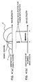
- Fig.4(a) shows the disposition of a signal channel being disposed arbitrarily and a Raman amplifying band in accordance with one pumping light wavelength
- Fig.4 (b) shows the disposition of pumping wavelength.
- the Raman amplifying band in accordance with this pumping wavelength comes to be in the state shown by the sign X' in Fig. 4 (a) .
- the signal channel is disposed at the position shown in Fig. 4 (a), and the position is out of the gain peak of the Raman amplifying band in accordance with the pumping wavelength of the wavelength X, therefore, the utilizing efficiency of the pumping light power is low (the utilizing efficiency depends on the conditions but that is lowered by about 10%, compared with the most effectively utilized case) and higher pumping light power is required.
- the Raman amplifying band in accordance with this pumping wavelength comes to be in the state shown by the sign Y' in Fig.4(a).
- the signal channel is disposed at the gain peak position of the Raman amplifying band (Raman gain) by the pumping wavelength of the wavelength Y, therefore, the pumping light power effectively contributes to the Raman amplification and only lower pumping light power is enough.
- the pumping wavelength when, in case of the pumping wavelength having been disposed at the wavelength X, the pumping wavelength is relocated at the wavelength Y, the output (pumping light power) of the pumping light source in the Raman amplifying section 2 can be further lowered.
- the pumping light disposing the pumping light wavelength most suitably for the disposition of the signal channel can reduce power.
- the number of wavelengths being outputted from the wavelength variable pumping light source 23 in the Raman amplifying section 2 is three, and the three pumping light wavelengths are denoted as ⁇ p1 , ⁇ p2 , and ⁇ p3
- the band including these pumping light wavelengths is called the pumping band
- the band of the signal light to be amplified by these three pumping light is called the signal band (amplifying band).
- the signal band is divided into three blocks, and the three blocks are denoted as the block 1, the block 2 and the block 3, and the average values of the optical output power (average optical output power) of the entire signal light being included in each of the blocks 1, 2 and 3 are denoted as P out1 , P out2 , and P out3 respectively.
- the desired average value of the optical output power (desired average optical output power : desired optical output power) of the entire signal light being included in the signal band is denoted as P ref .
- the desired average optical output power P ref shows the same value of the average optical output power of the rare earth element doped fiber amplifying section 8, in the case where the rare earth element doped fiber amplifying section 8 is added.
- the matrix B ij [ i : pumpinglightwavelength number (in this case, 1 to 3), j : block number (in this case, 1 to 3) ] is the coefficient showing the change of the deviations
- the matrix B ij is calculated beforehand in a manner mentioned hereinafter and its calculated result is stored in the memory of the computer 71.
- the matrix B ij is obtained as the gradient of the line showing the change of the deviations
- the control section 7 controls the pumping light wavelength outputted from the wavelength variable pumping light source 23 in the Raman amplifying section 2 based on the ⁇ pi calculated by using the equation (1) mentioned above. That is, the ⁇ pi is calculated by using the equation (1) at the computer 71 in the control section 7, and the wavelength and power controller 72 controls the pumping light wavelength outputted from the wavelength variable pumping light source 23 in the Raman amplifying section 2 based on the calculated ⁇ pi .
- the specific controlling method (control algorithm) for the pumping light wavelength control is explained later.
- the pumping light power control can be executed.
- the pumping light power control basically, almost the same control for the pumping light wavelength control mentioned above is executed.
- the matrix A ij [ i : pumping light wavelength number (in this case, 1 to 3) , j : block number (in this case, 1 to 3) ] is the coefficient showing the deviations
- the control section 7 controls the pumping light power outputted from the wavelength variable pumping light source 23 in the Raman amplifying section 2 based on the ⁇ P pi calculated by using the equation (2) mentioned above. That is, the ⁇ P pi is calculated by using the equation (2) at the computer 71 in the control section 7, and the wavelength and power controller 72 controls the pumping light power outputted from the wavelength variable pumping light source 23 in the Raman amplifying section 2 based on the calculated ⁇ P pi .
- the specific controlling method (control algorithm) for the pumping light power control is explained later.
- the same desired average optical output power P ref is used at the all blocks.
- the embodiment of the present invention is not limited to this, for example, it is possible that tilt control is executed by using different desired average optical output power P ref for each of blocks. Thereby, the gain flatness can be more surely realized.
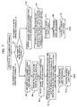
- the optical amplifier according to the embodiment of the present invention has the structure mentioned above, next, referring to Fig.7, the processes at the time when the number of operating channels is added are explained. Still, the number of operating channels is assumed to be set to be equal to A or less, at the initial stage wherein there is introduced the optical transmission system having been the optical amplifier according to the embodiment of the present invention installed.
- the number of operating channels is added, it is judged whether the number of entire operating channels is equal to the number of allowable channels A or less (step S1) . For example, this judgment can be executed at the computer 71 in the control section 7, or by an operator.
- the signal light of the operating channels of the entire band is amplified by the Raman amplifying section 2, without adding the rare earth element doped fiber amplifying section 8.
- the optical amplifier 1 has the structure shown in Fig.1.
- the processes proceed to the route of the right side shown in Fig. 7, and the control section 7 obtains (detects) the channel disposition (the wavelengths of the operating channels) and their optical output power from the optical spectrum monitor 5 (step S2) .
- the computer 71 in the control section 7 reads out the pumping light wavelength being set as a default value (default pumping light wavelength) and the pumping light power being set as a default value (default pumping light power) corresponding to the wavelength and the power of the signal light of the operating channels being disposed arbitrarily in the entire band from the memory. Based on this, the wavelength and power controller 72 in the control section 7 controls the wavelength variable pumping light source 23 in the Raman amplifying section 2.
- the pumping light wavelength and the pumping light power outputted from the wavelength variable pumping light source 23 are set to be the default pumping light wavelength and the default pumping light power (default values) that can amplify the signal light of the operating channels disposing arbitrarily in the entire band (step S3).
- the processes for the pumping light power control (step S4), the pumping light wavelength control (step S5), and the pumping light power control (step S6) for the wavelength variable pumping light source 23 in the Raman amplifying section 2 are executed sequentially. The contents of processes for the pumping light power control and the pumping light wavelength control will be explained later.
- the pumping light power control there are executed the pumping light power control, the pumping light wavelength control, and the pumping light power control sequentially.
- the embodiment of the present invention is not limited to this, and the order, the combination and the number of times of this control can be set arbitrary.
- the pumping light wavelength control and the pumping light power control are executed in order.
- the rare earth element doped fiber amplifying section 8 is added, and the signal light of the operating channels in the entire band is amplified by the Raman amplifying section 2 and the rare earth element doped fiber amplifying section 8.
- the processes proceed to the route of the left side shown in Fig.7, and the rare earth element doped fiber amplifying section 8 is added via the optical switches 3 and 4 (step S7).
- the route is changed by switching over the optical switches 3 and 4 (step S8) .
- the optical amplifier 1 has the structure shown in Fig.2. Further, when the rare earth element doped fiber-amplifying section 8 is not connected via the optical switches 3 and 4, the step S8 is not necessary.
- the control section 7 executes the relocation of the pumping light wavelengths, by controlling the changes of the pumping light wavelengths of the Raman amplifying section 2. That is, in the case where the number of operating channels is equal to the number of allowable channels A or less, the pumping light wavelengths of the Raman amplifying section 2 have been disposed such that the signal light of the entire operating channels being arbitrarily disposed in the entire band can be amplified.
- the pumping light wavelengths are relocated such that the signal light of the operating channels contained within the band located out of the amplifying band of the rare earth element doped fiber amplifier can be amplifies by the Raman amplifying section 2.
- control section 7 obtains (detects) the channel disposition (the wavelengths of the operating channels) and their optical output power from the optical spectrummonitor 5 (step S9) .
- the computer 71 in the control section 7 reads out the pumping light wavelength being set as a default value (default pumping light wavelength) and the pumping light power being set as a default value (default pumping light power) corresponding to the wavelength and the power of the signal light of the operating channels contained within the band located out of the amplifying band of the rare earth element doped fiber amplifier from the memory. Based on this, the wavelength and power controller 72 in the control section 7 controls the wavelength variable pumping light source 23 in the Raman amplifying section 2.
- the pumping light wavelength and the pumping light power outputted from the wavelength variable pumping light source 23 are set to be the default pumping light wavelengths ( ⁇ 01 to ⁇ 0n ) and the default pumping light power (default values) that can amplify the signal light of the operating channels contained within the band located out of the amplifying band of the rare earth element doped fiber amplifier (step S10).
- step S11 the processes for the pumping light wavelength control (step S11) and the pumping light power control (step S12) for the wavelength variable pumping light source 23 in the Raman amplifying section 2 are executed sequentially.
- the contents of processes for the pumping light power control and the pumping light wavelength control will be explained later.
- the pumping light wavelength control and the pumping light power control are executed sequentially.
- the embodiment of the present invention is not limited to this, and the order, the combination and the number of times of these control can be set arbitrary.
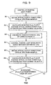
- the computer 71 in the control section 7 reads (obtains) the optical output power being monitored every wavelength by the optical spectrum monitor 5 (step A1) , and calculates the average value of the optical output power of each block (average optical output power) P out1 , P out2 , and P out3 (P outj : j is the block number). Still, in the case where the monitor is provided with the function calculating the average value, it is enough that the computer 71 reads only the calculated average value.
- the signal light of the operating channels being disposed arbitrarily in the entire band is amplified by the Raman amplifying section 2.
- the signal light of the operating channels contained within the band located out of the amplifying band of the rare earth element doped fiber amplifier is amplified by the Raman amplifying section 2.
- the amplifying band (signal band) to be amplified by the Raman amplifying section 2 is different between the case where the number of operating channels is equal to the number of allowable channels A or less and the case where the number of operating channels becomes greater than the number of allowable channels A.
- the average value of the optical output power from the optical spectrum monitor 5 of each block which the entire band is divided into is calculated.
- the average value of the optical output power from the optical spectrum monitor 5 of each block which the band located out of the amplifying band of the rare earth element doped fiber amplifier is divided into is calculated.
- the computer 71 reads the desired average optical output power (the desired value) P ref being set as the system set value, and calculates the deviations
- the computer 71 reads out the B ij (in some cases, the B ij is shown as [B] ) from the memory, and by using the read B ij and the deviations
- the ⁇ pi is the wavelength difference for the pumping light wavelength set by the previous pumping light wavelength control, that is, the manipulated variable.
- the wavelength and power controller 72 controls the pumping light wavelength to be outputted from the wavelength variable pumping light source 23 in the Raman amplifying section 2, based on the ⁇ pi calculated at the computer 71 (step A4) . Further, in the case where the wavelength variable pumping light source 23 is a source to which relative values are inputted, the ⁇ pi can be inputted as it is. On the other hand, in the case where the wavelength variable pumping light source 23 is a source to which absolute values are inputted, respective pumping light wavelength ⁇ i is calculated, based on the ⁇ pi , and the calculated each pumping light wavelength ⁇ i is inputted.
- the computer 71 reads the optical output power being monitored every wavelength by the optical spectrummonitor 5 (step A5), and calculates the average values P out1 , P out2 , and P out3 , (P outj , : j is the block number) of the optical output power of each block. Further, when the monitor side is provided with a function calculating the average values, it is enough that the computer 71 only reads the calculated average values.
- the computer 71 reads the desired average optical output power P ref being set as the system set value, and calculates the deviations
- the computer 71 judges whether each of the deviations
- the pumping light wavelength control by the control section 7 is repeated until the deviation
- the pumping light wavelength control is repeated until the deviation
- the process is not limited to the process mentioned above.
- the process can be repeated until any root mean square of the deviations
- the pumping light wavelength control is executed by feedback control, however, according to the embodiment of the present invention, the control is not limited to this control.
- the pumping light wavelength control mentioned above has been executed beforehand, a table in which the pumping light wavelengths are corresponded to the number of operating channels and the disposition of the operating channels is arranged, and the table is stored in the memory of the computer 71 .
- the computer 71 obtains the number of operating channels and the disposition of the operating channels from monitoring control light and sets the pumping light wavelength by referring to the table storing in the memory (feed forward control) . This control is also possible.
- the computer 71 in the control section 7 reads (obtains) the optical output power being monitored every wavelength by the optical spectrum monitor 5 (step B1) , and calculates the average value of the optical output power of each block (average optical output power) P out1 , P out2 , and P out3 (P outj : j is the block number) . Further, in the case where the monitor is provided with the function calculating the average value, it is enough that the computer 71 reads only the calculated average value.
- the signal light of the operating channels being disposed arbitrarily in the entire band is amplified by the Raman amplifying section 2.
- the signal light of the operating channels contained within the band located out of the amplifying band of the rare earth element doped fiber amplifier is amplified by the Raman amplifying section 2.
- the amplifying band (signal band) to be amplified by the Raman amplifying section 2 is different between the case where the number of operating channels is equal to the number of allowable channels A or less and the case where the number of operating channels becomes greater than the number of allowable channels A.
- the average value of the optical output power from the optical spectrum monitor 5 of each block which the entire band is divided into is calculated.
- the average value of the optical output power from the optical spectrum monitor 5 of each block which the band located out of the amplifying band of the rare earth element doped fiber amplifier is divided into is calculated.
- the computer 71 reads the desired average optical output power (the desired value) P ref being set as the system set value, and calculates the deviations
- the computer 71 reads out the A ij (in some cases, the A ij is shown as [A] ) from the memory, and by using the read A ij and the deviation
- the ⁇ P pi is the power difference for the pumping light power set by the previous pumping light power control, that is, the manipulated variable(step B3).
- the wavelength and power controller 72 controls the pumping light power to be outputted from the wavelength variable pumping light source 23 in the Raman amplifying section 2, based on the ⁇ P pi calculated at the computer 71 (step B4). Further, in the case where the wavelength variable pumping light source 23 is a source to which relative values are inputted, the ⁇ P pi can be inputted as it is. On the other hand, in the case where the wavelength variable pumping light source 23 is a source to which absolute values are inputted, respective pumping light power P i is calculated, based on the ⁇ P pi , and the calculated each pumping light power P i is inputted.
- the computer 71 reads (obtains) the optical output power being monitored every wavelength by the optical spectrum monitor 5 (step B5), and calculates the average values P out1 , P out2, and P out3 , (P outj : J is the block number) of the optical output power of each block. Further, when the monitor side is provided with a function calculating the average values, it is enough that the computer 71 only reads the calculated average values.
- the computer 71 reads the desired average optical output power P ref being set as the system set value, and calculates the deviations
- the computer 71 judges whether each of the deviations
- the pumping light power control by the control section 7 is repeated until the deviation
- the pumping light power control is repeated until the deviation
- the process is not limited to the process mentioned above.
- the process can be repeated until any root mean square of the deviations
- the pumping light power control is executed by feedback control, however, according to the embodiment of the present invention, the control is not limited to this control.
- the pumping light power control mentioned above has been executed beforehand, a table in which the pumping light wavelengths are corresponded to the number of operating channels and the disposition of the operating channels is arranged, and the table is stored in the memory of the computer 71.
- the computer 71 obtains the number of operating channels and the disposition of the operating channels from monitoring control light and sets the pumping light power by referring to the table storing in the memory (feed forward control). This control is also possible.
- the pumping light power can be reduced at the time when the number of operating channels is small such as at the initial installation time, further the pumping light source cost occupying the greater part of the optical amplifier can be reduced, consequently the present invention has the advantages mentioned above.
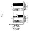
- Fig.10 is a drawing showing the relation between the number of operating channels and the relative required pumping light power, wherein there is performed a comparison among optical amplifiers shown by "a”, “b”, and “c", i.e. the optical amplifier according to the embodiment of the present invention (an EDFA is used as the rare earth element doped fiber amplifier) (shown by “c”); a Raman optical amplifier having a general structure(shown by “a”);, and an optical amplifier (hybrid optical amplifier) being composed of a Raman amplifier and a rare earth element doped fiber amplifier (EDFA) (shown by "b") ; .
- the relative required pumping light power is shown as a ratio for pumping light power to be installed in a Raman amplifier having a general structure.
- the Raman amplifier having the general structure basically installs pumping light power requiring at the case where the number of operating channels is the largest, therefore, the installing pumping light power is constant without depending on the number of operating channels.
- the hybrid optical amplifier has the EDFA installed from the initial installation time, therefore, the installing pumping light power becomes almost constant without depending on the number of operating channels.
- the optical amplifier according to the embodiment of the present invention has a rare earth element doped fiber amplifying section (for example, an EDFA) installed in the case where the number of operating channels becomes greater than the number of allowable channels A.
- the control section 7 relocates the pumping wavelength of the Raman amplifying section, therefore, in the case where the number of operating channels is small such as at the initial installation time (for example, at the case where the number of operating channels is equal to the number of allowable channels A or less), it is not necessary to install the rare earth element doped fiber amplifying section (for example, the EDFA), consequently, the pumping light power for the rare earth element doped fiber amplifying section can be reduced, and the cost of the pumping light source can be also reduced.
- the rare earth element doped fiber amplifying section for example, an EDFA
- the wavelength variable pumping light source 23 is used as the pumping light source of the Raman amplifying section 2, and the most suitable pumping light power and the most suitable pumping light wavelength are obtained corresponding to the disposition of the operating channels (wavelength of the signal light) by executing the pumping light power control and the pumping light wavelength control. Therefore, the pumping light power as well as the cost of the pumping light source can be further reduced. Furthermore, by adopting the structure, in which the pumping light source in the Raman amplifying section is added corresponding to the addition of the number of operating channels, at the time when the number of operating channels is small, the pumping light power and the cost of pumping light source can be further reduced.
Landscapes
- Physics & Mathematics (AREA)
- Electromagnetism (AREA)
- Engineering & Computer Science (AREA)
- Plasma & Fusion (AREA)
- Optics & Photonics (AREA)
- Computer Networks & Wireless Communication (AREA)
- Signal Processing (AREA)
- Lasers (AREA)
- Optical Modulation, Optical Deflection, Nonlinear Optics, Optical Demodulation, Optical Logic Elements (AREA)
Claims (13)
- Ein optischer Verstärker, umfassend:eine Raman-Verstärkungssektion (2), die zum Verstärken von Signallicht eines ganzen Bandes fähig ist, das aus einem Verstärkungsband eines mit seltenen Erden dotierten Faserverstärkers und einem weiteren Band, das eine Zahl von zulässigen Kanälen A hat, das sich außerhalb des Verstärkungsbandes befindet, besteht;eine mit seltenen Erden dotierte Faserverstärkungssektion (8), die für eine Verstärkung des Verstärkungsbandes anzuwenden ist, wobei die Zahl von arbeitenden Kanälen die Zahl von zulässigen Kanälen A überschreitet; undeine Steuersektion (7);wobei die Steuersektion (7) angepasst ist, die Wellenlänge von Pumplicht der Raman-Verstärkungssektion derart zu steuern, dass das Signallicht des ganzen Bandes verstärkt werden kann, in dem Fall, wo die Zahl von arbeitenden Kanälen gleich der von zulässigen Kanälen A oder kleiner ist; gekennzeichnet dadurch, dass die Steuersektion (7) angepasst ist, die Wellenlänge von Pumplicht der Raman-Verstärkungssektion (2) derart zu steuern, dass im wesentlichen nur das Signallicht des Bandes, das sich außerhalb des Verstärkungsbandes des mit seltenen Erden dotierten Faserverstärkers (8) befindet, durch die Raman-Verstärkungssektion (2) verstärkt werden kann, in dem Fall, wo die Zahl von arbeitenden Kanälen größer als die Zahl von zulässigen Kanälen A wird.
- Der optische Verstärker nach Anspruch 1, ferner umfassend:Schalter (3, 4), die ermöglichen, die Verbindungen der mit seltenen Erden dotierten Faserverstärkungssektion herzustellen.
- Der optische Verstärker nach Anspruch 1 oder 2, wobei das Band, das sich außerhalb des Verstärkungsbandes des mit seltenen Erden dotierten Faserverstärkers (8) befindet, ein Band auf der kurzen Wellenlängenseite ist, das dem Verstärkungsband des mit seltenen Erden dotierten Faserverstärkers (8) benachbart ist.
- Der optische Verstärker nach einem beliebigen von Ansprüchen 1 bis 3,
wobei der mit seltenen Erden dotierte Faserverstärker (8) ein mit Erbium dotierter Faserverstärker ist, das Verstärkungsband des mit seltenen Erden dotierten Faserverstärkers (8) ein C-Band oder ein L-Band ist, und
das Band, das sich außerhalb des Verstärkungsbandes des mit seltenen Erden dotierten Faserverstärkers (8) befindet, ein Band auf der kurzen Wellenlängenseite ist, benachbart dem C-Band oder dem L-Band. - Der optische Verstärker nach einem beliebigen von Ansprüchen 1 bis 4,
wobei die Raman-Verstärkungssektion (2) umfasst:eine in der Wellenlänge variable Pumplichtquelle (23). - Der optische Verstärker nach einem beliebigen von Ansprüchen 1 bis 5,
wobei die Steuersektion (7) konfiguriert ist, die Wellenlänge von Pumplicht der Raman-Verstärkungssektion (2) zu ändern basierend auf der Wellenlänge des Signallichts des arbeitenden Kanals, der in dem Band enthalten ist, das sich außerhalb des Verstärkungsbandes des mit seltenen Erden dotierten Faserverstärkers (8) befindet, in dem Fall, wo die Zahl von arbeitenden Kanälen größer als die Zahl von zulässigen Kanälen A wird. - Der optische Verstärker nach einem beliebigen von Ansprüchen 1 bis 6, wobei die Steuersektion (7) konfiguriert ist, die Wellenlänge von Pumplicht der Raman-Verstärkungssektion (2) basierend auf optischer Ausgangsleistung des ganzen Bandes zu steuern, in dem Fall, wo die Zahl von arbeitenden Kanälen gleich der von zulässigen Kanälen A oder kleiner ist, wohingegen die Steuersektion (7) konfiguriert ist, die Wellenlänge von Pumplicht der Raman-Verstärkungssektion (2) basierend auf optischer Ausgangsleistung des Bandes, das sich außerhalb des Verstärkungsbandes des mit seltenen Erden dotierten Faserverstärkers (8) befindet, zu steuern, in dem Fall, wo die Zahl von arbeitenden Kanälen größer als die Zahl von zulässigen Kanälen A wird.
- Der optische Verstärker nach Anspruch 7, wobei in dem Fall, wo die Zahl von arbeitenden Kanälen gleich der von zulässigen Kanälen A oder kleiner ist,
die Steuersektion (7) konfiguriert ist, die Wellenlänge von Pumplicht der Raman-Verstärkungssektion (2) zu steuern, bis eine beliebige Abweichung, die nicht mehr als ein vorbestimmter Wert wird, einer mittleren optischen Ausgangsleistung von jedem von Blöcken, in die das ganze Band unterteilt ist, von einer gewünschten optischen Ausgangsleistung existiert, wohingegen in dem Fall, wo die Zahl von arbeitenden Kanälen größer als die Zahl von zulässigen Kanälen A wird, die Steuersektion (7) die Wellenlänge von Pumplicht der Raman-Verstärkungssektion steuert, bis eine beliebige Abweichung, die nicht mehr als ein vorbestimmter Wert wird, einer mittleren optischen Ausgangsleistung von jedem von Blöcken, in die das Band, das sich außerhalb des Verstärkungsbandes des mit seltenen ersten dotierten Faserverstärkers (8) befindet, unterteilt ist, von einer gewünschten optischen Ausgangsleistung existiert. - Der optische Verstärker nach Anspruch 7, wobei in dem Fall, wo die Zahl von arbeitenden Kanälen gleich der von zulässigen Kanälen A oder kleiner ist, die Steuersektion (7) konfiguriert ist, die Wellenlänge von Pumplicht der Raman-Verstärkungssektion zu steuern, bis ein beliebiger quadratischer Mittelwert von Abweichungen, der nicht mehr als ein vorbestimmter Wert wird, einer mittleren optischen Ausgangsleistung von jedem von Blöcken, in die das ganze Band unterteilt ist, von einer gewünschten optischen Ausgangsleistung existiert, wohingegen in dem Fall, wo die Zahl von arbeitenden Kanälen größer als die Zahl von zulässigen Kanälen A wird, die Steuersektion (7) die Wellenlänge von Pumplicht der Raman-Verstärkungssektion steuert, bis ein beliebiger quadratischer Mittelwert von Abweichungen, der nicht mehr als ein vorbestimmter Wert wird, einer mittleren optischen Ausgangsleistung von jedem von Blöcken, in die das Band, das sich außerhalb des Verstärkungsbandes des mit seltenen Erden dotierten optischen Faserverstärkers (8) befindet, unterteilt ist, von einer gewünschten optischen Ausgangsleistung existiert.
- Der optische Verstärker nach einem beliebigen von Ansprüchen 1 bis 9, wobei die Steuersektion (7) konfiguriert ist, die Pumplichtleistung der Raman-Verstärkungssektion (2) basierend auf einer optischen Ausgangsleistung des ganzen Bandes zu steuern, in dem Fall, wo die Zahl von arbeitenden Kanälen gleich der von zulässigen Kanälen A oder kleiner ist, wohingegen die Steuersektion (7) konfiguriert ist, die Pumplichtleistung der Raman-Verstärkungssektion (2) basierend auf einer optischen Ausgangsleistung des Bandes, das sich außerhalb des Verstärkungsbandes des mit seltenen Erden dotierten Faserverstärkers befindet, zu steuern, in dem Fall, wo die Zahl von arbeitenden Kanälen größer als die Zahl von zulässigen Kanälen A wird.
- Der optische Verstärker nach Anspruch 10, wobei in dem Fall, wo die Zahl von arbeitenden Kanälen gleich der von zulässigen Kanälen A oder kleiner ist, die Steuersektion (7) konfiguriert ist, die Pumplichtleistung der Raman-Verstärkungssektion (2) zu steuern, bis ein beliebiger quadratischer Mittelwert von Abweichungen, der nicht mehr als ein vorbestimmter Wert wird, einer mittleren optischen Ausgangsleistung von jedem von Blöcken, in die das ganze Band unterteilt ist, von einer gewünschten optischen Ausgangsleistung existiert, wohingegen in dem Fall, wo die Zahl von arbeitenden Kanälen größer als die Zahl von zulässigen Kanälen A wird, die Steuersektion (7) die Pumplichtleistung der Raman-Verstärkungssektion (2) steuert, bis ein beliebiger quadratischer Mittelwert von Abweichungen, der nicht mehr als ein vorbestimmter Wert wird, einer mittleren optischen Ausgangsleistung von jedem von Blöcken, in die das Band, das sich außerhalb des Verstärkungsbandes des mit seltenen Erden dotierten Faserverstärkers (8) befindet, unterteilt ist, von einer gewünschten optischen Ausgangsleistung existiert.
- Der optische Verstärker nach Anspruch 10, wobei in dem Fall, wo die Zahl von arbeitenden Kanälen gleich der von zulässigen Kanälen A oder kleiner ist, die Steuersektion (7) konfiguriert ist, die Pumplichtleistung der Raman-Verstärkungssektion zu steuern, bis eine beliebige Abweichung eines quadratischer Mittelwertes, die nicht mehr als ein vorbestimmter Wert wird, einer mittleren optischen Ausgangsleistung von jedem von Blöcken, in die das ganze Band unterteilt ist, von einer gewünschten optischen Ausgangsleistung existiert, wohingegen in dem Fall, wo die Zahl von arbeitenden Kanälen größer als die Zahl von zulässigen Kanälen A wird, die Steuersektion (7) die Pumplichtleistung der Raman-Verstärkungssektion (2) steuert, bis eine beliebige Abweichung, die nicht mehr als ein vorbestimmter Wert wird, einer mittleren optischen Ausgangsleistung von jedem von Blöcken, in die das Band, das sich außerhalb des Verstärkungsbandes des mit seltenen Erden dotierten Faserverstärkers befindet, unterteilt ist, von einer gewünschten optischen Ausgangsleistung existiert.
- Ein Steuerverfahren für einen Raman-Verstärker, der fähig ist zum Verstärken von Signallicht des ganzen Bandes, das aus einem Verstärkungsband eines mit seltenen Erden dotierten Faserverstärkers und einem Band, das eine Zahl von zulässigen Kanälen A hat, das sich außerhalb des Verstärkungsbandes befindet, besteht;
das Verfahren die Schritte umfassend zum:Steuern der Pumpwellenlänge des Raman-Verstärkers (2) derart, dass das Signallicht des ganzen Bandes verstärkt werden kann, in dem Fall, wo die Zahl von arbeitenden Kanälen gleich der von zulässigen Kanälen A oder kleiner ist; undandererseits Steuern der Pumpwellenlänge des Raman-Verstärkers (2) derart, dass im wesentlichen nur das Signallicht des Bandes, das sich außerhalb des Verstärkungsbandes des mit seltenen Erden dotierten Faserverstärkers (8) befindet, durch den Raman-Verstärker (2) verstärkt werden kann, in dem Fall, wo die Zahl von arbeitenden Kanälen größer als die Zahl von zulässigen Kanälen A wird.
Applications Claiming Priority (2)
| Application Number | Priority Date | Filing Date | Title |
|---|---|---|---|
| JP2004100795A JP4113852B2 (ja) | 2004-03-30 | 2004-03-30 | 光増幅器及びラマン増幅器の制御方法 |
| JP2004100795 | 2004-03-30 |
Publications (2)
| Publication Number | Publication Date |
|---|---|
| EP1583186A1 EP1583186A1 (de) | 2005-10-05 |
| EP1583186B1 true EP1583186B1 (de) | 2007-05-30 |
Family
ID=34879998
Family Applications (1)
| Application Number | Title | Priority Date | Filing Date |
|---|---|---|---|
| EP04018359A Expired - Lifetime EP1583186B1 (de) | 2004-03-30 | 2004-08-03 | Optischer Verstärker und Methode zur Kontrolle eines Raman-Verstärkers |
Country Status (4)
| Country | Link |
|---|---|
| US (1) | US7095553B2 (de) |
| EP (1) | EP1583186B1 (de) |
| JP (1) | JP4113852B2 (de) |
| DE (1) | DE602004006714T2 (de) |
Families Citing this family (8)
| Publication number | Priority date | Publication date | Assignee | Title |
|---|---|---|---|---|
| US7522334B2 (en) * | 2004-02-19 | 2009-04-21 | Corvis Equipment Corporation | Optical communication systems including optical amplifiers and amplification methods with flat noise figure profile |
| US7142356B2 (en) * | 2005-02-24 | 2006-11-28 | At&T Corp. | Fast dynamic gain control in an optical fiber amplifier |
| US7672042B2 (en) | 2005-02-24 | 2010-03-02 | At&T Corporation | Fast dynamic gain control in an optical fiber amplifier |
| US8441721B2 (en) * | 2009-12-30 | 2013-05-14 | Alcatel Lucent | System and method of Raman amplifier pump control |
| US20120002283A1 (en) * | 2010-06-30 | 2012-01-05 | Chongjin Xie | Method and apparatus for raman co-pumps |
| CN108957905A (zh) * | 2017-05-19 | 2018-12-07 | 中国电子科技集团公司第四十研究所 | 一种多用途edfa参数快速优化设计装置及其制作、使用方法 |
| CN111698033B (zh) * | 2020-05-21 | 2021-08-13 | 武汉光迅科技股份有限公司 | 混合光纤放大器、光信号放大方法及光通信系统 |
| CN111711055B (zh) * | 2020-06-11 | 2021-09-10 | 武汉光迅科技股份有限公司 | 双向拉曼掺铒光纤混合放大器、光信号放大方法及系统 |
Family Cites Families (6)
| Publication number | Priority date | Publication date | Assignee | Title |
|---|---|---|---|---|
| JPH1184440A (ja) | 1997-09-03 | 1999-03-26 | Nippon Telegr & Teleph Corp <Ntt> | 光増幅器及びこれを用いた光伝送システム |
| EP2306605B1 (de) * | 1998-07-23 | 2012-05-23 | The Furukawa Electric Co., Ltd. | Pumpeinheit für einen Ramanverstärker und Ramanverstärker, der dieselbe aufweist |
| EP1170628B1 (de) * | 2000-01-14 | 2018-08-01 | The Furukawa Electric Co., Ltd. | Ramanverstärker |
| KR20030068578A (ko) * | 2001-01-05 | 2003-08-21 | 후지쯔 가부시끼가이샤 | 광대역 wdm 광 화이버 전송 시스템에서의 장파장채널의 제어 방식 |
| JP4188573B2 (ja) * | 2001-04-09 | 2008-11-26 | 株式会社日立製作所 | 光増幅器の増幅帯域拡大方法、光増幅器、及び増設ユニット |
| JP4007812B2 (ja) | 2002-01-18 | 2007-11-14 | 富士通株式会社 | ラマン増幅器および波長多重光通信システム、並びに、ラマン増幅の制御方法 |
-
2004
- 2004-03-30 JP JP2004100795A patent/JP4113852B2/ja not_active Expired - Fee Related
- 2004-07-21 US US10/895,315 patent/US7095553B2/en not_active Expired - Fee Related
- 2004-08-03 DE DE602004006714T patent/DE602004006714T2/de not_active Expired - Lifetime
- 2004-08-03 EP EP04018359A patent/EP1583186B1/de not_active Expired - Lifetime
Non-Patent Citations (1)
| Title |
|---|
| None * |
Also Published As
| Publication number | Publication date |
|---|---|
| US7095553B2 (en) | 2006-08-22 |
| JP2005286227A (ja) | 2005-10-13 |
| EP1583186A1 (de) | 2005-10-05 |
| JP4113852B2 (ja) | 2008-07-09 |
| US20050219681A1 (en) | 2005-10-06 |
| DE602004006714D1 (de) | 2007-07-12 |
| DE602004006714T2 (de) | 2008-01-24 |
Similar Documents
| Publication | Publication Date | Title |
|---|---|---|
| EP1182808B1 (de) | Optischer Verstärker mit Kontrolle des Pumplichtes für Ramanverstärkung | |
| JP3363003B2 (ja) | 光増幅装置及び光増幅装置を用いた光伝送システム | |
| US6958856B2 (en) | Raman amplifier, raman amplifier control method, and optical communication system | |
| JP5223638B2 (ja) | 光受信モジュールの制御方法 | |
| EP1909414B1 (de) | Dynamischer Raman-Neigungsausgleich | |
| US7995269B2 (en) | Cost effective optical transmission with fast raman tilt transient control | |
| EP1317083B1 (de) | Ramanverstärkungssystem und optische Signalübertragung unter Verwendung desselben | |
| JP2000013316A (ja) | 光増幅器 | |
| JP4725951B2 (ja) | 波長多重信号光の増幅方法および光増幅器 | |
| EP1583186B1 (de) | Optischer Verstärker und Methode zur Kontrolle eines Raman-Verstärkers | |
| US6580549B1 (en) | Wavelength-multiplexed light amplifying apparatus, optical amplifier and optical add-and-drop apparatus using wavelength-multiplexed light amplifying basic unit | |
| EP1788730B1 (de) | Optische Verstärkungseinrichtung mit Kompensation von Faserabschnittverlustanstiegen | |
| JP2001168841A (ja) | 波長多重光増幅器 | |
| JP2002344054A (ja) | 光増幅装置および光伝送システム | |
| JP4484565B2 (ja) | チルト補償機能を有する多段光増幅器 | |
| US7636192B2 (en) | Method, apparatus and system for cost effective optical transmission with fast Raman tilt transient control | |
| EP0959640B1 (de) | Optischer Schalter und optisches Netzwerk | |
| US7813650B2 (en) | Optical system | |
| JP3379104B2 (ja) | 波長多重伝送用光増幅器 | |
| JP2004296581A (ja) | 光増幅装置およびその制御方法 | |
| JPH11186643A (ja) | Wdm伝送用光増幅器 |
Legal Events
| Date | Code | Title | Description |
|---|---|---|---|
| PUAI | Public reference made under article 153(3) epc to a published international application that has entered the european phase |
Free format text: ORIGINAL CODE: 0009012 |
|
| AK | Designated contracting states |
Kind code of ref document: A1 Designated state(s): AT BE BG CH CY CZ DE DK EE ES FI FR GB GR HU IE IT LI LU MC NL PL PT RO SE SI SK TR |
|
| AX | Request for extension of the european patent |
Extension state: AL HR LT LV MK |
|
| 17P | Request for examination filed |
Effective date: 20051114 |
|
| AKX | Designation fees paid |
Designated state(s): DE FR GB |
|
| GRAP | Despatch of communication of intention to grant a patent |
Free format text: ORIGINAL CODE: EPIDOSNIGR1 |
|
| GRAS | Grant fee paid |
Free format text: ORIGINAL CODE: EPIDOSNIGR3 |
|
| GRAA | (expected) grant |
Free format text: ORIGINAL CODE: 0009210 |
|
| AK | Designated contracting states |
Kind code of ref document: B1 Designated state(s): DE FR GB |
|
| REG | Reference to a national code |
Ref country code: GB Ref legal event code: FG4D |
|
| REF | Corresponds to: |
Ref document number: 602004006714 Country of ref document: DE Date of ref document: 20070712 Kind code of ref document: P |
|
| ET | Fr: translation filed | ||
| PLBE | No opposition filed within time limit |
Free format text: ORIGINAL CODE: 0009261 |
|
| STAA | Information on the status of an ep patent application or granted ep patent |
Free format text: STATUS: NO OPPOSITION FILED WITHIN TIME LIMIT |
|
| 26N | No opposition filed |
Effective date: 20080303 |
|
| PGFP | Annual fee paid to national office [announced via postgrant information from national office to epo] |
Ref country code: GB Payment date: 20120801 Year of fee payment: 9 |
|
| PGFP | Annual fee paid to national office [announced via postgrant information from national office to epo] |
Ref country code: FR Payment date: 20120823 Year of fee payment: 9 Ref country code: DE Payment date: 20120731 Year of fee payment: 9 |
|
| GBPC | Gb: european patent ceased through non-payment of renewal fee |
Effective date: 20130803 |
|
| PG25 | Lapsed in a contracting state [announced via postgrant information from national office to epo] |
Ref country code: DE Free format text: LAPSE BECAUSE OF NON-PAYMENT OF DUE FEES Effective date: 20140301 |
|
| REG | Reference to a national code |
Ref country code: FR Ref legal event code: ST Effective date: 20140430 |
|
| REG | Reference to a national code |
Ref country code: DE Ref legal event code: R119 Ref document number: 602004006714 Country of ref document: DE Effective date: 20140301 |
|
| PG25 | Lapsed in a contracting state [announced via postgrant information from national office to epo] |
Ref country code: GB Free format text: LAPSE BECAUSE OF NON-PAYMENT OF DUE FEES Effective date: 20130803 |
|
| PG25 | Lapsed in a contracting state [announced via postgrant information from national office to epo] |
Ref country code: FR Free format text: LAPSE BECAUSE OF NON-PAYMENT OF DUE FEES Effective date: 20130902 |