EP1582918A1 - Photothermographisches Material und Bilderzeugungsverfahren - Google Patents
Photothermographisches Material und Bilderzeugungsverfahren Download PDFInfo
- Publication number
- EP1582918A1 EP1582918A1 EP05005364A EP05005364A EP1582918A1 EP 1582918 A1 EP1582918 A1 EP 1582918A1 EP 05005364 A EP05005364 A EP 05005364A EP 05005364 A EP05005364 A EP 05005364A EP 1582918 A1 EP1582918 A1 EP 1582918A1
- Authority
- EP
- European Patent Office
- Prior art keywords
- group
- photothermographic material
- image forming
- silver
- material according
- Prior art date
- Legal status (The legal status is an assumption and is not a legal conclusion. Google has not performed a legal analysis and makes no representation as to the accuracy of the status listed.)
- Granted
Links
- 239000000463 material Substances 0.000 title claims abstract description 280
- 238000000034 method Methods 0.000 title claims abstract description 167
- -1 silver halide Chemical class 0.000 claims abstract description 475
- 229910052709 silver Inorganic materials 0.000 claims abstract description 239
- 239000004332 silver Substances 0.000 claims abstract description 239
- 238000011161 development Methods 0.000 claims abstract description 170
- GGCZERPQGJTIQP-UHFFFAOYSA-N sodium;9,10-dioxoanthracene-2-sulfonic acid Chemical compound [Na+].C1=CC=C2C(=O)C3=CC(S(=O)(=O)O)=CC=C3C(=O)C2=C1 GGCZERPQGJTIQP-UHFFFAOYSA-N 0.000 claims abstract description 72
- 239000003638 chemical reducing agent Substances 0.000 claims abstract description 63
- 208000015181 infectious disease Diseases 0.000 claims abstract description 54
- 230000002458 infectious effect Effects 0.000 claims abstract description 54
- 239000011230 binding agent Substances 0.000 claims abstract description 36
- 150000001875 compounds Chemical class 0.000 claims description 216
- 238000010438 heat treatment Methods 0.000 claims description 165
- 239000000126 substance Substances 0.000 claims description 143
- 125000000623 heterocyclic group Chemical group 0.000 claims description 134
- 125000001424 substituent group Chemical group 0.000 claims description 128
- 125000004435 hydrogen atom Chemical group [H]* 0.000 claims description 87
- 125000000217 alkyl group Chemical group 0.000 claims description 81
- 125000003118 aryl group Chemical group 0.000 claims description 74
- BQCADISMDOOEFD-UHFFFAOYSA-N Silver Chemical compound [Ag] BQCADISMDOOEFD-UHFFFAOYSA-N 0.000 claims description 64
- 229910021612 Silver iodide Inorganic materials 0.000 claims description 59
- JKFYKCYQEWQPTM-UHFFFAOYSA-N 2-azaniumyl-2-(4-fluorophenyl)acetate Chemical compound OC(=O)C(N)C1=CC=C(F)C=C1 JKFYKCYQEWQPTM-UHFFFAOYSA-N 0.000 claims description 57
- 229940045105 silver iodide Drugs 0.000 claims description 57
- 125000004432 carbon atom Chemical group C* 0.000 claims description 53
- 230000035945 sensitivity Effects 0.000 claims description 49
- 125000003545 alkoxy group Chemical group 0.000 claims description 46
- 229910052757 nitrogen Inorganic materials 0.000 claims description 45
- 239000003795 chemical substances by application Substances 0.000 claims description 44
- 125000004104 aryloxy group Chemical group 0.000 claims description 37
- 125000003277 amino group Chemical group 0.000 claims description 35
- 238000003825 pressing Methods 0.000 claims description 31
- 125000002252 acyl group Chemical group 0.000 claims description 28
- 125000004414 alkyl thio group Chemical group 0.000 claims description 28
- 125000005110 aryl thio group Chemical group 0.000 claims description 26
- NBIIXXVUZAFLBC-UHFFFAOYSA-N Phosphoric acid Chemical compound OP(O)(O)=O NBIIXXVUZAFLBC-UHFFFAOYSA-N 0.000 claims description 24
- IJGRMHOSHXDMSA-UHFFFAOYSA-N Atomic nitrogen Chemical compound N#N IJGRMHOSHXDMSA-UHFFFAOYSA-N 0.000 claims description 22
- 230000001235 sensitizing effect Effects 0.000 claims description 21
- 229910052717 sulfur Inorganic materials 0.000 claims description 20
- 125000000472 sulfonyl group Chemical group *S(*)(=O)=O 0.000 claims description 17
- 229910019142 PO4 Inorganic materials 0.000 claims description 14
- 125000001931 aliphatic group Chemical group 0.000 claims description 13
- 229910000147 aluminium phosphate Inorganic materials 0.000 claims description 12
- 125000004434 sulfur atom Chemical group 0.000 claims description 11
- 230000031700 light absorption Effects 0.000 claims description 10
- 239000010452 phosphate Substances 0.000 claims description 9
- 125000003452 oxalyl group Chemical group *C(=O)C(*)=O 0.000 claims description 8
- OAICVXFJPJFONN-UHFFFAOYSA-N Phosphorus Chemical compound [P] OAICVXFJPJFONN-UHFFFAOYSA-N 0.000 claims description 7
- 150000002429 hydrazines Chemical class 0.000 claims description 7
- 229910052698 phosphorus Inorganic materials 0.000 claims description 7
- 239000012491 analyte Substances 0.000 claims description 6
- 229910052760 oxygen Inorganic materials 0.000 claims description 6
- 239000001301 oxygen Substances 0.000 claims description 6
- 239000011574 phosphorus Substances 0.000 claims description 6
- 229920002554 vinyl polymer Polymers 0.000 claims description 6
- 230000000903 blocking effect Effects 0.000 claims description 3
- 230000001678 irradiating effect Effects 0.000 claims description 3
- 150000004010 onium ions Chemical group 0.000 claims description 3
- MYMOFIZGZYHOMD-UHFFFAOYSA-N Dioxygen Chemical compound O=O MYMOFIZGZYHOMD-UHFFFAOYSA-N 0.000 claims description 2
- 239000003550 marker Substances 0.000 claims description 2
- 150000003013 phosphoric acid derivatives Chemical class 0.000 claims description 2
- JRZJOMJEPLMPRA-UHFFFAOYSA-N olefin Natural products CCCCCCCC=C JRZJOMJEPLMPRA-UHFFFAOYSA-N 0.000 claims 1
- 239000010410 layer Substances 0.000 description 272
- 239000000243 solution Substances 0.000 description 121
- 239000006185 dispersion Substances 0.000 description 115
- 238000000576 coating method Methods 0.000 description 106
- 239000011248 coating agent Substances 0.000 description 104
- 239000002245 particle Substances 0.000 description 84
- XLYOFNOQVPJJNP-UHFFFAOYSA-N water Substances O XLYOFNOQVPJJNP-UHFFFAOYSA-N 0.000 description 80
- 206010070834 Sensitisation Diseases 0.000 description 61
- 230000008313 sensitization Effects 0.000 description 61
- 239000000839 emulsion Substances 0.000 description 57
- OKKJLVBELUTLKV-UHFFFAOYSA-N Methanol Chemical compound OC OKKJLVBELUTLKV-UHFFFAOYSA-N 0.000 description 55
- 150000003839 salts Chemical class 0.000 description 53
- 238000002360 preparation method Methods 0.000 description 52
- 229920000126 latex Polymers 0.000 description 48
- 239000004816 latex Substances 0.000 description 48
- 229920000642 polymer Polymers 0.000 description 46
- 239000011241 protective layer Substances 0.000 description 44
- 239000000203 mixture Substances 0.000 description 41
- 239000007864 aqueous solution Substances 0.000 description 37
- 125000003396 thiol group Chemical group [H]S* 0.000 description 37
- 239000000975 dye Substances 0.000 description 35
- 125000003917 carbamoyl group Chemical group [H]N([H])C(*)=O 0.000 description 33
- 230000000274 adsorptive effect Effects 0.000 description 32
- 125000004433 nitrogen atom Chemical group N* 0.000 description 31
- 238000006243 chemical reaction Methods 0.000 description 30
- 125000005843 halogen group Chemical group 0.000 description 29
- 230000008569 process Effects 0.000 description 28
- SQGYOTSLMSWVJD-UHFFFAOYSA-N silver(1+) nitrate Chemical compound [Ag+].[O-]N(=O)=O SQGYOTSLMSWVJD-UHFFFAOYSA-N 0.000 description 28
- 125000002887 hydroxy group Chemical group [H]O* 0.000 description 26
- 150000003378 silver Chemical class 0.000 description 26
- 229920002451 polyvinyl alcohol Polymers 0.000 description 25
- 239000007787 solid Substances 0.000 description 25
- HEMHJVSKTPXQMS-UHFFFAOYSA-M Sodium hydroxide Chemical compound [OH-].[Na+] HEMHJVSKTPXQMS-UHFFFAOYSA-M 0.000 description 24
- 238000002156 mixing Methods 0.000 description 24
- 239000002253 acid Substances 0.000 description 23
- 125000004442 acylamino group Chemical group 0.000 description 23
- MCMNRKCIXSYSNV-UHFFFAOYSA-N Zirconium dioxide Chemical compound O=[Zr]=O MCMNRKCIXSYSNV-UHFFFAOYSA-N 0.000 description 22
- 239000013078 crystal Substances 0.000 description 22
- 230000003287 optical effect Effects 0.000 description 22
- 108010010803 Gelatin Proteins 0.000 description 21
- 229920000159 gelatin Polymers 0.000 description 21
- 235000019322 gelatine Nutrition 0.000 description 21
- 235000011852 gelatine desserts Nutrition 0.000 description 21
- PPBRXRYQALVLMV-UHFFFAOYSA-N Styrene Chemical compound C=CC1=CC=CC=C1 PPBRXRYQALVLMV-UHFFFAOYSA-N 0.000 description 20
- 239000002904 solvent Substances 0.000 description 20
- 239000004372 Polyvinyl alcohol Substances 0.000 description 19
- JUJWROOIHBZHMG-UHFFFAOYSA-N Pyridine Chemical group C1=CC=NC=C1 JUJWROOIHBZHMG-UHFFFAOYSA-N 0.000 description 19
- 125000004453 alkoxycarbonyl group Chemical group 0.000 description 19
- 125000004397 aminosulfonyl group Chemical group NS(=O)(=O)* 0.000 description 19
- 239000010419 fine particle Substances 0.000 description 19
- 239000008273 gelatin Substances 0.000 description 19
- 229910052739 hydrogen Inorganic materials 0.000 description 19
- 239000001257 hydrogen Substances 0.000 description 19
- 125000001449 isopropyl group Chemical group [H]C([H])([H])C([H])(*)C([H])([H])[H] 0.000 description 19
- 235000019422 polyvinyl alcohol Nutrition 0.000 description 19
- 238000010521 absorption reaction Methods 0.000 description 18
- 239000000654 additive Substances 0.000 description 18
- 230000015572 biosynthetic process Effects 0.000 description 18
- 229940125904 compound 1 Drugs 0.000 description 18
- RAXXELZNTBOGNW-UHFFFAOYSA-N imidazole Natural products C1=CNC=N1 RAXXELZNTBOGNW-UHFFFAOYSA-N 0.000 description 18
- 125000002496 methyl group Chemical group [H]C([H])([H])* 0.000 description 18
- 125000001997 phenyl group Chemical group [H]C1=C([H])C([H])=C(*)C([H])=C1[H] 0.000 description 18
- 235000019646 color tone Nutrition 0.000 description 17
- 238000007254 oxidation reaction Methods 0.000 description 17
- 239000002002 slurry Substances 0.000 description 17
- VYPSYNLAJGMNEJ-UHFFFAOYSA-N Silicium dioxide Chemical compound O=[Si]=O VYPSYNLAJGMNEJ-UHFFFAOYSA-N 0.000 description 16
- 125000003342 alkenyl group Chemical group 0.000 description 16
- 125000005161 aryl oxy carbonyl group Chemical group 0.000 description 16
- 125000001495 ethyl group Chemical group [H]C([H])([H])C([H])([H])* 0.000 description 16
- 230000003595 spectral effect Effects 0.000 description 16
- 239000004094 surface-active agent Substances 0.000 description 16
- XEKOWRVHYACXOJ-UHFFFAOYSA-N Ethyl acetate Chemical compound CCOC(C)=O XEKOWRVHYACXOJ-UHFFFAOYSA-N 0.000 description 15
- 239000011324 bead Substances 0.000 description 15
- 125000001951 carbamoylamino group Chemical group C(N)(=O)N* 0.000 description 15
- 229910052736 halogen Inorganic materials 0.000 description 15
- 230000003647 oxidation Effects 0.000 description 15
- 239000004576 sand Substances 0.000 description 15
- 125000000565 sulfonamide group Chemical group 0.000 description 15
- KFZMGEQAYNKOFK-UHFFFAOYSA-N Isopropanol Chemical compound CC(C)O KFZMGEQAYNKOFK-UHFFFAOYSA-N 0.000 description 14
- 125000000304 alkynyl group Chemical group 0.000 description 14
- 125000004429 atom Chemical group 0.000 description 14
- 239000012153 distilled water Substances 0.000 description 14
- 229910001961 silver nitrate Inorganic materials 0.000 description 14
- 238000002834 transmittance Methods 0.000 description 14
- 125000004391 aryl sulfonyl group Chemical group 0.000 description 13
- 229910052751 metal Inorganic materials 0.000 description 13
- 239000002184 metal Substances 0.000 description 13
- 235000011007 phosphoric acid Nutrition 0.000 description 13
- LFSXCDWNBUNEEM-UHFFFAOYSA-N phthalazine Chemical compound C1=NN=CC2=CC=CC=C21 LFSXCDWNBUNEEM-UHFFFAOYSA-N 0.000 description 13
- 229910052714 tellurium Inorganic materials 0.000 description 13
- ZMXDDKWLCZADIW-UHFFFAOYSA-N N,N-Dimethylformamide Chemical compound CN(C)C=O ZMXDDKWLCZADIW-UHFFFAOYSA-N 0.000 description 12
- KYQCOXFCLRTKLS-UHFFFAOYSA-N Pyrazine Chemical compound C1=CN=CC=N1 KYQCOXFCLRTKLS-UHFFFAOYSA-N 0.000 description 12
- 229910052798 chalcogen Inorganic materials 0.000 description 12
- 229920001577 copolymer Polymers 0.000 description 12
- 238000009826 distribution Methods 0.000 description 12
- 238000005259 measurement Methods 0.000 description 12
- 239000000178 monomer Substances 0.000 description 12
- 125000001820 oxy group Chemical group [*:1]O[*:2] 0.000 description 12
- 125000001436 propyl group Chemical group [H]C([*])([H])C([H])([H])C([H])([H])[H] 0.000 description 12
- 125000004149 thio group Chemical group *S* 0.000 description 12
- LFQSCWFLJHTTHZ-UHFFFAOYSA-N Ethanol Chemical compound CCO LFQSCWFLJHTTHZ-UHFFFAOYSA-N 0.000 description 11
- 125000004423 acyloxy group Chemical group 0.000 description 11
- 125000004390 alkyl sulfonyl group Chemical group 0.000 description 11
- QGZKDVFQNNGYKY-UHFFFAOYSA-O ammonium group Chemical group [NH4+] QGZKDVFQNNGYKY-UHFFFAOYSA-O 0.000 description 11
- 229940125782 compound 2 Drugs 0.000 description 11
- 238000004132 cross linking Methods 0.000 description 11
- 230000001965 increasing effect Effects 0.000 description 11
- 125000005647 linker group Chemical group 0.000 description 11
- 229920000139 polyethylene terephthalate Polymers 0.000 description 11
- 239000005020 polyethylene terephthalate Substances 0.000 description 11
- 229920003048 styrene butadiene rubber Polymers 0.000 description 11
- 125000000999 tert-butyl group Chemical group [H]C([H])([H])C(*)(C([H])([H])[H])C([H])([H])[H] 0.000 description 11
- KAKZBPTYRLMSJV-UHFFFAOYSA-N Butadiene Chemical compound C=CC=C KAKZBPTYRLMSJV-UHFFFAOYSA-N 0.000 description 10
- QAOWNCQODCNURD-UHFFFAOYSA-N Sulfuric acid Chemical compound OS(O)(=O)=O QAOWNCQODCNURD-UHFFFAOYSA-N 0.000 description 10
- TZCXTZWJZNENPQ-UHFFFAOYSA-L barium sulfate Chemical compound [Ba+2].[O-]S([O-])(=O)=O TZCXTZWJZNENPQ-UHFFFAOYSA-L 0.000 description 10
- 239000002585 base Substances 0.000 description 10
- 229910052799 carbon Inorganic materials 0.000 description 10
- 150000004696 coordination complex Chemical class 0.000 description 10
- 238000000151 deposition Methods 0.000 description 10
- 230000000694 effects Effects 0.000 description 10
- 238000011156 evaluation Methods 0.000 description 10
- 150000002367 halogens Chemical class 0.000 description 10
- 239000007788 liquid Substances 0.000 description 10
- 239000003960 organic solvent Substances 0.000 description 10
- 230000036961 partial effect Effects 0.000 description 10
- XNGIFLGASWRNHJ-UHFFFAOYSA-N phthalic acid Chemical compound OC(=O)C1=CC=CC=C1C(O)=O XNGIFLGASWRNHJ-UHFFFAOYSA-N 0.000 description 10
- NLKNQRATVPKPDG-UHFFFAOYSA-M potassium iodide Substances [K+].[I-] NLKNQRATVPKPDG-UHFFFAOYSA-M 0.000 description 10
- 239000011347 resin Substances 0.000 description 10
- 229920005989 resin Polymers 0.000 description 10
- 238000003756 stirring Methods 0.000 description 10
- ZGOQRUPIKZGTLQ-UHFFFAOYSA-N 1,2-benzothiazole 1-oxide;sodium Chemical compound [Na].C1=CC=C2S(=O)N=CC2=C1 ZGOQRUPIKZGTLQ-UHFFFAOYSA-N 0.000 description 9
- KAESVJOAVNADME-UHFFFAOYSA-N Pyrrole Chemical compound C=1C=CNC=1 KAESVJOAVNADME-UHFFFAOYSA-N 0.000 description 9
- 241001061127 Thione Species 0.000 description 9
- 125000003282 alkyl amino group Chemical group 0.000 description 9
- 238000000149 argon plasma sintering Methods 0.000 description 9
- 125000001769 aryl amino group Chemical group 0.000 description 9
- 150000001721 carbon Chemical group 0.000 description 9
- 125000004093 cyano group Chemical group *C#N 0.000 description 9
- 230000008021 deposition Effects 0.000 description 9
- 238000011033 desalting Methods 0.000 description 9
- 238000010586 diagram Methods 0.000 description 9
- UKMSUNONTOPOIO-UHFFFAOYSA-N docosanoic acid Chemical compound CCCCCCCCCCCCCCCCCCCCCC(O)=O UKMSUNONTOPOIO-UHFFFAOYSA-N 0.000 description 9
- 238000001035 drying Methods 0.000 description 9
- 150000002500 ions Chemical class 0.000 description 9
- QJGQUHMNIGDVPM-UHFFFAOYSA-N nitrogen group Chemical group [N] QJGQUHMNIGDVPM-UHFFFAOYSA-N 0.000 description 9
- 239000000049 pigment Substances 0.000 description 9
- 239000007962 solid dispersion Substances 0.000 description 9
- PORWMNRCUJJQNO-UHFFFAOYSA-N tellurium atom Chemical compound [Te] PORWMNRCUJJQNO-UHFFFAOYSA-N 0.000 description 9
- 229910052693 Europium Inorganic materials 0.000 description 8
- VVQNEPGJFQJSBK-UHFFFAOYSA-N Methyl methacrylate Chemical compound COC(=O)C(C)=C VVQNEPGJFQJSBK-UHFFFAOYSA-N 0.000 description 8
- 125000003178 carboxy group Chemical group [H]OC(*)=O 0.000 description 8
- 230000001276 controlling effect Effects 0.000 description 8
- 238000001816 cooling Methods 0.000 description 8
- 235000014113 dietary fatty acids Nutrition 0.000 description 8
- 235000019441 ethanol Nutrition 0.000 description 8
- 239000000194 fatty acid Substances 0.000 description 8
- 229930195729 fatty acid Natural products 0.000 description 8
- 238000001914 filtration Methods 0.000 description 8
- 125000002883 imidazolyl group Chemical group 0.000 description 8
- 125000005462 imide group Chemical group 0.000 description 8
- 125000001434 methanylylidene group Chemical group [H]C#[*] 0.000 description 8
- 235000021317 phosphate Nutrition 0.000 description 8
- PBMFSQRYOILNGV-UHFFFAOYSA-N pyridazine Chemical compound C1=CC=NN=C1 PBMFSQRYOILNGV-UHFFFAOYSA-N 0.000 description 8
- XSCHRSMBECNVNS-UHFFFAOYSA-N quinoxaline Chemical compound N1=CC=NC2=CC=CC=C21 XSCHRSMBECNVNS-UHFFFAOYSA-N 0.000 description 8
- 230000009467 reduction Effects 0.000 description 8
- 238000006722 reduction reaction Methods 0.000 description 8
- 239000011593 sulfur Substances 0.000 description 8
- QGZKDVFQNNGYKY-UHFFFAOYSA-N Ammonia Chemical compound N QGZKDVFQNNGYKY-UHFFFAOYSA-N 0.000 description 7
- WKBOTKDWSSQWDR-UHFFFAOYSA-N Bromine atom Chemical group [Br] WKBOTKDWSSQWDR-UHFFFAOYSA-N 0.000 description 7
- PCNDJXKNXGMECE-UHFFFAOYSA-N Phenazine Natural products C1=CC=CC2=NC3=CC=CC=C3N=C21 PCNDJXKNXGMECE-UHFFFAOYSA-N 0.000 description 7
- 239000004743 Polypropylene Substances 0.000 description 7
- NINIDFKCEFEMDL-UHFFFAOYSA-N Sulfur Chemical compound [S] NINIDFKCEFEMDL-UHFFFAOYSA-N 0.000 description 7
- FZWLAAWBMGSTSO-UHFFFAOYSA-N Thiazole Chemical group C1=CSC=N1 FZWLAAWBMGSTSO-UHFFFAOYSA-N 0.000 description 7
- 230000005540 biological transmission Effects 0.000 description 7
- 150000001787 chalcogens Chemical class 0.000 description 7
- 239000000084 colloidal system Substances 0.000 description 7
- 125000004122 cyclic group Chemical group 0.000 description 7
- 125000000753 cycloalkyl group Chemical group 0.000 description 7
- 239000000428 dust Substances 0.000 description 7
- 150000002148 esters Chemical group 0.000 description 7
- 150000004665 fatty acids Chemical class 0.000 description 7
- 230000009477 glass transition Effects 0.000 description 7
- 125000000449 nitro group Chemical group [O-][N+](*)=O 0.000 description 7
- 229920001155 polypropylene Polymers 0.000 description 7
- 239000011148 porous material Substances 0.000 description 7
- 239000002243 precursor Substances 0.000 description 7
- UMJSCPRVCHMLSP-UHFFFAOYSA-N pyridine Natural products COC1=CC=CN=C1 UMJSCPRVCHMLSP-UHFFFAOYSA-N 0.000 description 7
- 230000005070 ripening Effects 0.000 description 7
- 229920006395 saturated elastomer Polymers 0.000 description 7
- CVYDEWKUJFCYJO-UHFFFAOYSA-M sodium;docosanoate Chemical compound [Na+].CCCCCCCCCCCCCCCCCCCCCC([O-])=O CVYDEWKUJFCYJO-UHFFFAOYSA-M 0.000 description 7
- 125000003831 tetrazolyl group Chemical group 0.000 description 7
- JYEUMXHLPRZUAT-UHFFFAOYSA-N 1,2,3-triazine Chemical group C1=CN=NN=C1 JYEUMXHLPRZUAT-UHFFFAOYSA-N 0.000 description 6
- LYCAIKOWRPUZTN-UHFFFAOYSA-N Ethylene glycol Chemical compound OCCO LYCAIKOWRPUZTN-UHFFFAOYSA-N 0.000 description 6
- CZPWVGJYEJSRLH-UHFFFAOYSA-N Pyrimidine Chemical compound C1=CN=CN=C1 CZPWVGJYEJSRLH-UHFFFAOYSA-N 0.000 description 6
- BUGBHKTXTAQXES-UHFFFAOYSA-N Selenium Chemical compound [Se] BUGBHKTXTAQXES-UHFFFAOYSA-N 0.000 description 6
- 229910052771 Terbium Inorganic materials 0.000 description 6
- 150000007513 acids Chemical class 0.000 description 6
- 238000004061 bleaching Methods 0.000 description 6
- 229910052801 chlorine Inorganic materials 0.000 description 6
- JHIVVAPYMSGYDF-UHFFFAOYSA-N cyclohexanone Chemical compound O=C1CCCCC1 JHIVVAPYMSGYDF-UHFFFAOYSA-N 0.000 description 6
- 125000000113 cyclohexyl group Chemical group [H]C1([H])C([H])([H])C([H])([H])C([H])(*)C([H])([H])C1([H])[H] 0.000 description 6
- DOIRQSBPFJWKBE-UHFFFAOYSA-N dibutyl phthalate Chemical compound CCCCOC(=O)C1=CC=CC=C1C(=O)OCCCC DOIRQSBPFJWKBE-UHFFFAOYSA-N 0.000 description 6
- 238000005516 engineering process Methods 0.000 description 6
- OGPBJKLSAFTDLK-UHFFFAOYSA-N europium atom Chemical compound [Eu] OGPBJKLSAFTDLK-UHFFFAOYSA-N 0.000 description 6
- NBVXSUQYWXRMNV-UHFFFAOYSA-N fluoromethane Chemical compound FC NBVXSUQYWXRMNV-UHFFFAOYSA-N 0.000 description 6
- 230000006870 function Effects 0.000 description 6
- PCHJSUWPFVWCPO-UHFFFAOYSA-N gold Chemical compound [Au] PCHJSUWPFVWCPO-UHFFFAOYSA-N 0.000 description 6
- 229910052737 gold Inorganic materials 0.000 description 6
- 239000010931 gold Substances 0.000 description 6
- 238000003384 imaging method Methods 0.000 description 6
- 229910052740 iodine Inorganic materials 0.000 description 6
- 239000003921 oil Substances 0.000 description 6
- 125000005740 oxycarbonyl group Chemical group [*:1]OC([*:2])=O 0.000 description 6
- 125000004430 oxygen atom Chemical group O* 0.000 description 6
- ISWSIDIOOBJBQZ-UHFFFAOYSA-N phenol group Chemical group C1(=CC=CC=C1)O ISWSIDIOOBJBQZ-UHFFFAOYSA-N 0.000 description 6
- 229920000728 polyester Polymers 0.000 description 6
- 239000000843 powder Substances 0.000 description 6
- 229910052711 selenium Inorganic materials 0.000 description 6
- AQRYNYUOKMNDDV-UHFFFAOYSA-M silver behenate Chemical compound [Ag+].CCCCCCCCCCCCCCCCCCCCCC([O-])=O AQRYNYUOKMNDDV-UHFFFAOYSA-M 0.000 description 6
- ADZWSOLPGZMUMY-UHFFFAOYSA-M silver bromide Chemical compound [Ag]Br ADZWSOLPGZMUMY-UHFFFAOYSA-M 0.000 description 6
- NHQVTOYJPBRYNG-UHFFFAOYSA-M sodium;2,4,7-tri(propan-2-yl)naphthalene-1-sulfonate Chemical compound [Na+].CC(C)C1=CC(C(C)C)=C(S([O-])(=O)=O)C2=CC(C(C)C)=CC=C21 NHQVTOYJPBRYNG-UHFFFAOYSA-M 0.000 description 6
- 238000001179 sorption measurement Methods 0.000 description 6
- JOYRKODLDBILNP-UHFFFAOYSA-N urethane group Chemical group NC(=O)OCC JOYRKODLDBILNP-UHFFFAOYSA-N 0.000 description 6
- 230000000007 visual effect Effects 0.000 description 6
- IMROMDMJAWUWLK-UHFFFAOYSA-N Ethenol Chemical compound OC=C IMROMDMJAWUWLK-UHFFFAOYSA-N 0.000 description 5
- SIKJAQJRHWYJAI-UHFFFAOYSA-N Indole Chemical compound C1=CC=C2NC=CC2=C1 SIKJAQJRHWYJAI-UHFFFAOYSA-N 0.000 description 5
- FOIXSVOLVBLSDH-UHFFFAOYSA-N Silver ion Chemical compound [Ag+] FOIXSVOLVBLSDH-UHFFFAOYSA-N 0.000 description 5
- 239000002174 Styrene-butadiene Substances 0.000 description 5
- WYURNTSHIVDZCO-UHFFFAOYSA-N Tetrahydrofuran Chemical group C1CCOC1 WYURNTSHIVDZCO-UHFFFAOYSA-N 0.000 description 5
- 229910052784 alkaline earth metal Inorganic materials 0.000 description 5
- 150000001450 anions Chemical class 0.000 description 5
- 239000003125 aqueous solvent Substances 0.000 description 5
- 125000003710 aryl alkyl group Chemical group 0.000 description 5
- 125000000656 azaniumyl group Chemical group [H][N+]([H])([H])[*] 0.000 description 5
- DMSMPAJRVJJAGA-UHFFFAOYSA-N benzo[d]isothiazol-3-one Chemical compound C1=CC=C2C(=O)NSC2=C1 DMSMPAJRVJJAGA-UHFFFAOYSA-N 0.000 description 5
- IOJUPLGTWVMSFF-UHFFFAOYSA-N benzothiazole Chemical group C1=CC=C2SC=NC2=C1 IOJUPLGTWVMSFF-UHFFFAOYSA-N 0.000 description 5
- 125000003354 benzotriazolyl group Chemical group N1N=NC2=C1C=CC=C2* 0.000 description 5
- 125000000484 butyl group Chemical group [H]C([*])([H])C([H])([H])C([H])([H])C([H])([H])[H] 0.000 description 5
- 230000008859 change Effects 0.000 description 5
- 229920001971 elastomer Polymers 0.000 description 5
- 238000000407 epitaxy Methods 0.000 description 5
- 229910052731 fluorine Inorganic materials 0.000 description 5
- 125000002485 formyl group Chemical group [H]C(*)=O 0.000 description 5
- 229910001385 heavy metal Inorganic materials 0.000 description 5
- 238000004519 manufacturing process Methods 0.000 description 5
- 239000006224 matting agent Substances 0.000 description 5
- 125000000956 methoxy group Chemical group [H]C([H])([H])O* 0.000 description 5
- 125000001624 naphthyl group Chemical group 0.000 description 5
- 150000007524 organic acids Chemical class 0.000 description 5
- 125000003355 oxamoyl group Chemical group C(C(=O)N)(=O)* 0.000 description 5
- 229920002635 polyurethane Polymers 0.000 description 5
- 239000004814 polyurethane Substances 0.000 description 5
- 229910052700 potassium Inorganic materials 0.000 description 5
- 125000000714 pyrimidinyl group Chemical group 0.000 description 5
- 239000005060 rubber Substances 0.000 description 5
- DUIOPKIIICUYRZ-UHFFFAOYSA-N semicarbazide group Chemical group NNC(=O)N DUIOPKIIICUYRZ-UHFFFAOYSA-N 0.000 description 5
- 239000011734 sodium Substances 0.000 description 5
- 238000006467 substitution reaction Methods 0.000 description 5
- 125000000020 sulfo group Chemical group O=S(=O)([*])O[H] 0.000 description 5
- 125000000101 thioether group Chemical group 0.000 description 5
- 125000001425 triazolyl group Chemical group 0.000 description 5
- AFBBKYQYNPNMAT-UHFFFAOYSA-N 1h-1,2,4-triazol-1-ium-3-thiolate Chemical group SC=1N=CNN=1 AFBBKYQYNPNMAT-UHFFFAOYSA-N 0.000 description 4
- SMZOUWXMTYCWNB-UHFFFAOYSA-N 2-(2-methoxy-5-methylphenyl)ethanamine Chemical compound COC1=CC=C(C)C=C1CCN SMZOUWXMTYCWNB-UHFFFAOYSA-N 0.000 description 4
- NIXOWILDQLNWCW-UHFFFAOYSA-N 2-Propenoic acid Natural products OC(=O)C=C NIXOWILDQLNWCW-UHFFFAOYSA-N 0.000 description 4
- ZNQVEEAIQZEUHB-UHFFFAOYSA-N 2-ethoxyethanol Chemical compound CCOCCO ZNQVEEAIQZEUHB-UHFFFAOYSA-N 0.000 description 4
- ZCYVEMRRCGMTRW-UHFFFAOYSA-N 7553-56-2 Chemical group [I] ZCYVEMRRCGMTRW-UHFFFAOYSA-N 0.000 description 4
- 235000021357 Behenic acid Nutrition 0.000 description 4
- IAYPIBMASNFSPL-UHFFFAOYSA-N Ethylene oxide Chemical group C1CO1 IAYPIBMASNFSPL-UHFFFAOYSA-N 0.000 description 4
- WOBHKFSMXKNTIM-UHFFFAOYSA-N Hydroxyethyl methacrylate Chemical compound CC(=C)C(=O)OCCO WOBHKFSMXKNTIM-UHFFFAOYSA-N 0.000 description 4
- YNAVUWVOSKDBBP-UHFFFAOYSA-N Morpholine Chemical group C1COCCN1 YNAVUWVOSKDBBP-UHFFFAOYSA-N 0.000 description 4
- ZLMJMSJWJFRBEC-UHFFFAOYSA-N Potassium Chemical compound [K] ZLMJMSJWJFRBEC-UHFFFAOYSA-N 0.000 description 4
- WTKZEGDFNFYCGP-UHFFFAOYSA-N Pyrazole Chemical compound C=1C=NNC=1 WTKZEGDFNFYCGP-UHFFFAOYSA-N 0.000 description 4
- RWRDLPDLKQPQOW-UHFFFAOYSA-N Pyrrolidine Chemical group C1CCNC1 RWRDLPDLKQPQOW-UHFFFAOYSA-N 0.000 description 4
- SMWDFEZZVXVKRB-UHFFFAOYSA-N Quinoline Chemical compound N1=CC=CC2=CC=CC=C21 SMWDFEZZVXVKRB-UHFFFAOYSA-N 0.000 description 4
- KKEYFWRCBNTPAC-UHFFFAOYSA-N Terephthalic acid Chemical compound OC(=O)C1=CC=C(C(O)=O)C=C1 KKEYFWRCBNTPAC-UHFFFAOYSA-N 0.000 description 4
- DKGAVHZHDRPRBM-UHFFFAOYSA-N Tert-Butanol Chemical compound CC(C)(C)O DKGAVHZHDRPRBM-UHFFFAOYSA-N 0.000 description 4
- 229910052775 Thulium Inorganic materials 0.000 description 4
- 235000010724 Wisteria floribunda Nutrition 0.000 description 4
- 229910052783 alkali metal Inorganic materials 0.000 description 4
- 150000001340 alkali metals Chemical class 0.000 description 4
- 125000004466 alkoxycarbonylamino group Chemical group 0.000 description 4
- 125000005194 alkoxycarbonyloxy group Chemical group 0.000 description 4
- 125000004644 alkyl sulfinyl group Chemical group 0.000 description 4
- 125000005162 aryl oxy carbonyl amino group Chemical group 0.000 description 4
- 125000005135 aryl sulfinyl group Chemical group 0.000 description 4
- QVGXLLKOCUKJST-UHFFFAOYSA-N atomic oxygen Chemical compound [O] QVGXLLKOCUKJST-UHFFFAOYSA-N 0.000 description 4
- 229940116226 behenic acid Drugs 0.000 description 4
- 125000003785 benzimidazolyl group Chemical group N1=C(NC2=C1C=CC=C2)* 0.000 description 4
- 238000009835 boiling Methods 0.000 description 4
- 238000010504 bond cleavage reaction Methods 0.000 description 4
- CQEYYJKEWSMYFG-UHFFFAOYSA-N butyl acrylate Chemical compound CCCCOC(=O)C=C CQEYYJKEWSMYFG-UHFFFAOYSA-N 0.000 description 4
- 150000001768 cations Chemical class 0.000 description 4
- UOCJDOLVGGIYIQ-PBFPGSCMSA-N cefatrizine Chemical group S([C@@H]1[C@@H](C(N1C=1C(O)=O)=O)NC(=O)[C@H](N)C=2C=CC(O)=CC=2)CC=1CSC=1C=NNN=1 UOCJDOLVGGIYIQ-PBFPGSCMSA-N 0.000 description 4
- 210000000038 chest Anatomy 0.000 description 4
- 125000001309 chloro group Chemical group Cl* 0.000 description 4
- 238000007334 copolymerization reaction Methods 0.000 description 4
- 238000003851 corona treatment Methods 0.000 description 4
- FLKPEMZONWLCSK-UHFFFAOYSA-N diethyl phthalate Chemical compound CCOC(=O)C1=CC=CC=C1C(=O)OCC FLKPEMZONWLCSK-UHFFFAOYSA-N 0.000 description 4
- 238000007865 diluting Methods 0.000 description 4
- KZTYYGOKRVBIMI-UHFFFAOYSA-N diphenyl sulfone Chemical compound C=1C=CC=CC=1S(=O)(=O)C1=CC=CC=C1 KZTYYGOKRVBIMI-UHFFFAOYSA-N 0.000 description 4
- 238000010494 dissociation reaction Methods 0.000 description 4
- 230000005593 dissociations Effects 0.000 description 4
- 238000000295 emission spectrum Methods 0.000 description 4
- 125000001153 fluoro group Chemical group F* 0.000 description 4
- 125000001841 imino group Chemical group [H]N=* 0.000 description 4
- 125000003453 indazolyl group Chemical group N1N=C(C2=C1C=CC=C2)* 0.000 description 4
- 229910017053 inorganic salt Inorganic materials 0.000 description 4
- XEEYBQQBJWHFJM-UHFFFAOYSA-N iron Substances [Fe] XEEYBQQBJWHFJM-UHFFFAOYSA-N 0.000 description 4
- AWJUIBRHMBBTKR-UHFFFAOYSA-N isoquinoline Chemical compound C1=NC=CC2=CC=CC=C21 AWJUIBRHMBBTKR-UHFFFAOYSA-N 0.000 description 4
- ZLTPDFXIESTBQG-UHFFFAOYSA-N isothiazole Chemical compound C=1C=NSC=1 ZLTPDFXIESTBQG-UHFFFAOYSA-N 0.000 description 4
- CTAPFRYPJLPFDF-UHFFFAOYSA-N isoxazole Chemical compound C=1C=NOC=1 CTAPFRYPJLPFDF-UHFFFAOYSA-N 0.000 description 4
- 125000002971 oxazolyl group Chemical group 0.000 description 4
- 150000002989 phenols Chemical class 0.000 description 4
- 125000000951 phenoxy group Chemical group [H]C1=C([H])C([H])=C(O*)C([H])=C1[H] 0.000 description 4
- NBIIXXVUZAFLBC-UHFFFAOYSA-K phosphate Chemical compound [O-]P([O-])([O-])=O NBIIXXVUZAFLBC-UHFFFAOYSA-K 0.000 description 4
- BASFCYQUMIYNBI-UHFFFAOYSA-N platinum Chemical compound [Pt] BASFCYQUMIYNBI-UHFFFAOYSA-N 0.000 description 4
- 229920003229 poly(methyl methacrylate) Polymers 0.000 description 4
- 239000004848 polyfunctional curative Substances 0.000 description 4
- 239000004926 polymethyl methacrylate Substances 0.000 description 4
- 239000011591 potassium Substances 0.000 description 4
- 230000001681 protective effect Effects 0.000 description 4
- 229910052761 rare earth metal Inorganic materials 0.000 description 4
- 238000011160 research Methods 0.000 description 4
- 239000011669 selenium Substances 0.000 description 4
- 238000007767 slide coating Methods 0.000 description 4
- 230000003068 static effect Effects 0.000 description 4
- URAYPUMNDPQOKB-UHFFFAOYSA-N triacetin Chemical compound CC(=O)OCC(OC(C)=O)COC(C)=O URAYPUMNDPQOKB-UHFFFAOYSA-N 0.000 description 4
- 125000000391 vinyl group Chemical group [H]C([*])=C([H])[H] 0.000 description 4
- 238000005406 washing Methods 0.000 description 4
- 230000037303 wrinkles Effects 0.000 description 4
- 239000011701 zinc Substances 0.000 description 4
- NAWXUBYGYWOOIX-SFHVURJKSA-N (2s)-2-[[4-[2-(2,4-diaminoquinazolin-6-yl)ethyl]benzoyl]amino]-4-methylidenepentanedioic acid Chemical compound C1=CC2=NC(N)=NC(N)=C2C=C1CCC1=CC=C(C(=O)N[C@@H](CC(=C)C(O)=O)C(O)=O)C=C1 NAWXUBYGYWOOIX-SFHVURJKSA-N 0.000 description 3
- 229920002818 (Hydroxyethyl)methacrylate Polymers 0.000 description 3
- FYADHXFMURLYQI-UHFFFAOYSA-N 1,2,4-triazine Chemical compound C1=CN=NC=N1 FYADHXFMURLYQI-UHFFFAOYSA-N 0.000 description 3
- WYENVTYBQKCILL-UHFFFAOYSA-N 1,2,4-triazolidine-3,5-dithione Chemical group S=C1NNC(=S)N1 WYENVTYBQKCILL-UHFFFAOYSA-N 0.000 description 3
- MYRTYDVEIRVNKP-UHFFFAOYSA-N 1,2-Divinylbenzene Chemical compound C=CC1=CC=CC=C1C=C MYRTYDVEIRVNKP-UHFFFAOYSA-N 0.000 description 3
- HYZJCKYKOHLVJF-UHFFFAOYSA-N 1H-benzimidazole Chemical compound C1=CC=C2NC=NC2=C1 HYZJCKYKOHLVJF-UHFFFAOYSA-N 0.000 description 3
- JAAIPIWKKXCNOC-UHFFFAOYSA-N 1h-tetrazol-1-ium-5-thiolate Chemical group SC1=NN=NN1 JAAIPIWKKXCNOC-UHFFFAOYSA-N 0.000 description 3
- ZWEHNKRNPOVVGH-UHFFFAOYSA-N 2-Butanone Chemical compound CCC(C)=O ZWEHNKRNPOVVGH-UHFFFAOYSA-N 0.000 description 3
- CWJJAFQCTXFSTA-UHFFFAOYSA-N 4-methylphthalic acid Chemical compound CC1=CC=C(C(O)=O)C(C(O)=O)=C1 CWJJAFQCTXFSTA-UHFFFAOYSA-N 0.000 description 3
- KDCGOANMDULRCW-UHFFFAOYSA-N 7H-purine Chemical group N1=CNC2=NC=NC2=C1 KDCGOANMDULRCW-UHFFFAOYSA-N 0.000 description 3
- 229920002126 Acrylic acid copolymer Polymers 0.000 description 3
- OKTJSMMVPCPJKN-UHFFFAOYSA-N Carbon Chemical group [C] OKTJSMMVPCPJKN-UHFFFAOYSA-N 0.000 description 3
- JIGUQPWFLRLWPJ-UHFFFAOYSA-N Ethyl acrylate Chemical compound CCOC(=O)C=C JIGUQPWFLRLWPJ-UHFFFAOYSA-N 0.000 description 3
- YLQBMQCUIZJEEH-UHFFFAOYSA-N Furan Chemical group C=1C=COC=1 YLQBMQCUIZJEEH-UHFFFAOYSA-N 0.000 description 3
- DGAQECJNVWCQMB-PUAWFVPOSA-M Ilexoside XXIX Chemical compound C[C@@H]1CC[C@@]2(CC[C@@]3(C(=CC[C@H]4[C@]3(CC[C@@H]5[C@@]4(CC[C@@H](C5(C)C)OS(=O)(=O)[O-])C)C)[C@@H]2[C@]1(C)O)C)C(=O)O[C@H]6[C@@H]([C@H]([C@@H]([C@H](O6)CO)O)O)O.[Na+] DGAQECJNVWCQMB-PUAWFVPOSA-M 0.000 description 3
- 229910002420 LaOCl Inorganic materials 0.000 description 3
- WMFOQBRAJBCJND-UHFFFAOYSA-M Lithium hydroxide Chemical compound [Li+].[OH-] WMFOQBRAJBCJND-UHFFFAOYSA-M 0.000 description 3
- 229920000459 Nitrile rubber Polymers 0.000 description 3
- MUBZPKHOEPUJKR-UHFFFAOYSA-N Oxalic acid Chemical compound OC(=O)C(O)=O MUBZPKHOEPUJKR-UHFFFAOYSA-N 0.000 description 3
- 239000004698 Polyethylene Substances 0.000 description 3
- 229920001328 Polyvinylidene chloride Polymers 0.000 description 3
- KWYUFKZDYYNOTN-UHFFFAOYSA-M Potassium hydroxide Chemical compound [OH-].[K+] KWYUFKZDYYNOTN-UHFFFAOYSA-M 0.000 description 3
- DNIAPMSPPWPWGF-UHFFFAOYSA-N Propylene glycol Chemical compound CC(O)CO DNIAPMSPPWPWGF-UHFFFAOYSA-N 0.000 description 3
- 229910021607 Silver chloride Inorganic materials 0.000 description 3
- YSMRWXYRXBRSND-UHFFFAOYSA-N TOTP Chemical compound CC1=CC=CC=C1OP(=O)(OC=1C(=CC=CC=1)C)OC1=CC=CC=C1C YSMRWXYRXBRSND-UHFFFAOYSA-N 0.000 description 3
- YTPLMLYBLZKORZ-UHFFFAOYSA-N Thiophene Chemical group C=1C=CSC=1 YTPLMLYBLZKORZ-UHFFFAOYSA-N 0.000 description 3
- GWEVSGVZZGPLCZ-UHFFFAOYSA-N Titan oxide Chemical compound O=[Ti]=O GWEVSGVZZGPLCZ-UHFFFAOYSA-N 0.000 description 3
- DGEZNRSVGBDHLK-UHFFFAOYSA-N [1,10]phenanthroline Chemical compound C1=CN=C2C3=NC=CC=C3C=CC2=C1 DGEZNRSVGBDHLK-UHFFFAOYSA-N 0.000 description 3
- 238000000862 absorption spectrum Methods 0.000 description 3
- 125000002777 acetyl group Chemical group [H]C([H])([H])C(*)=O 0.000 description 3
- 239000000853 adhesive Substances 0.000 description 3
- 150000001298 alcohols Chemical class 0.000 description 3
- 229910052782 aluminium Inorganic materials 0.000 description 3
- 229910021529 ammonia Inorganic materials 0.000 description 3
- 125000002490 anilino group Chemical group [H]N(*)C1=C([H])C([H])=C([H])C([H])=C1[H] 0.000 description 3
- 239000003945 anionic surfactant Substances 0.000 description 3
- 230000002421 anti-septic effect Effects 0.000 description 3
- 125000005200 aryloxy carbonyloxy group Chemical group 0.000 description 3
- 125000003236 benzoyl group Chemical group [H]C1=C([H])C([H])=C(C([H])=C1[H])C(*)=O 0.000 description 3
- 125000001797 benzyl group Chemical group [H]C1=C([H])C([H])=C(C([H])=C1[H])C([H])([H])* 0.000 description 3
- 125000000051 benzyloxy group Chemical group [H]C1=C([H])C([H])=C(C([H])=C1[H])C([H])([H])O* 0.000 description 3
- 229910052793 cadmium Inorganic materials 0.000 description 3
- 239000013522 chelant Substances 0.000 description 3
- 238000010276 construction Methods 0.000 description 3
- 230000003247 decreasing effect Effects 0.000 description 3
- 238000003745 diagnosis Methods 0.000 description 3
- 229960002380 dibutyl phthalate Drugs 0.000 description 3
- VPWFPZBFBFHIIL-UHFFFAOYSA-L disodium 4-[(4-methyl-2-sulfophenyl)diazenyl]-3-oxidonaphthalene-2-carboxylate Chemical compound [Na+].[Na+].[O-]S(=O)(=O)C1=CC(C)=CC=C1N=NC1=C(O)C(C([O-])=O)=CC2=CC=CC=C12 VPWFPZBFBFHIIL-UHFFFAOYSA-L 0.000 description 3
- 150000002019 disulfides Chemical class 0.000 description 3
- JPIIVHIVGGOMMV-UHFFFAOYSA-N ditellurium Chemical compound [Te]=[Te] JPIIVHIVGGOMMV-UHFFFAOYSA-N 0.000 description 3
- 230000007613 environmental effect Effects 0.000 description 3
- 125000002534 ethynyl group Chemical group [H]C#C* 0.000 description 3
- 238000007765 extrusion coating Methods 0.000 description 3
- 150000004820 halides Chemical class 0.000 description 3
- 150000002391 heterocyclic compounds Chemical class 0.000 description 3
- 229920001519 homopolymer Polymers 0.000 description 3
- 230000036571 hydration Effects 0.000 description 3
- 238000006703 hydration reaction Methods 0.000 description 3
- XMBWDFGMSWQBCA-UHFFFAOYSA-N hydrogen iodide Chemical compound I XMBWDFGMSWQBCA-UHFFFAOYSA-N 0.000 description 3
- 230000000977 initiatory effect Effects 0.000 description 3
- 239000000314 lubricant Substances 0.000 description 3
- 210000004072 lung Anatomy 0.000 description 3
- 238000002844 melting Methods 0.000 description 3
- 230000008018 melting Effects 0.000 description 3
- 150000002739 metals Chemical class 0.000 description 3
- 239000011259 mixed solution Substances 0.000 description 3
- 125000001096 oxamoylamino group Chemical group C(C(=O)N)(=O)N* 0.000 description 3
- PNJWIWWMYCMZRO-UHFFFAOYSA-N pent‐4‐en‐2‐one Natural products CC(=O)CC=C PNJWIWWMYCMZRO-UHFFFAOYSA-N 0.000 description 3
- 230000000737 periodic effect Effects 0.000 description 3
- 125000005496 phosphonium group Chemical group 0.000 description 3
- 150000003022 phthalic acids Chemical class 0.000 description 3
- 239000004014 plasticizer Substances 0.000 description 3
- 235000013824 polyphenols Nutrition 0.000 description 3
- 229920000915 polyvinyl chloride Polymers 0.000 description 3
- 239000004800 polyvinyl chloride Substances 0.000 description 3
- 238000001556 precipitation Methods 0.000 description 3
- NDGRWYRVNANFNB-UHFFFAOYSA-N pyrazolidin-3-one Chemical compound O=C1CCNN1 NDGRWYRVNANFNB-UHFFFAOYSA-N 0.000 description 3
- 125000004076 pyridyl group Chemical group 0.000 description 3
- 238000002601 radiography Methods 0.000 description 3
- 239000002994 raw material Substances 0.000 description 3
- 229940065287 selenium compound Drugs 0.000 description 3
- 150000003343 selenium compounds Chemical class 0.000 description 3
- 239000010944 silver (metal) Substances 0.000 description 3
- HKZLPVFGJNLROG-UHFFFAOYSA-M silver monochloride Chemical compound [Cl-].[Ag+] HKZLPVFGJNLROG-UHFFFAOYSA-M 0.000 description 3
- 125000003808 silyl group Chemical group [H][Si]([H])([H])[*] 0.000 description 3
- 229910052708 sodium Inorganic materials 0.000 description 3
- APSBXTVYXVQYAB-UHFFFAOYSA-M sodium docusate Chemical compound [Na+].CCCCC(CC)COC(=O)CC(S([O-])(=O)=O)C(=O)OCC(CC)CCCC APSBXTVYXVQYAB-UHFFFAOYSA-M 0.000 description 3
- 229910001415 sodium ion Inorganic materials 0.000 description 3
- 239000003381 stabilizer Substances 0.000 description 3
- KZNICNPSHKQLFF-UHFFFAOYSA-N succinimide Chemical compound O=C1CCC(=O)N1 KZNICNPSHKQLFF-UHFFFAOYSA-N 0.000 description 3
- RWSOTUBLDIXVET-UHFFFAOYSA-O sulfonium group Chemical group [SH3+] RWSOTUBLDIXVET-UHFFFAOYSA-O 0.000 description 3
- 125000003375 sulfoxide group Chemical group 0.000 description 3
- 150000003464 sulfur compounds Chemical class 0.000 description 3
- GZCRRIHWUXGPOV-UHFFFAOYSA-N terbium atom Chemical compound [Tb] GZCRRIHWUXGPOV-UHFFFAOYSA-N 0.000 description 3
- 125000004044 trifluoroacetyl group Chemical group FC(C(=O)*)(F)F 0.000 description 3
- 229910052984 zinc sulfide Inorganic materials 0.000 description 3
- APXGHAWHVMPQBB-UHFFFAOYSA-N (hydroxyamino)urea Chemical class NC(=O)NNO APXGHAWHVMPQBB-UHFFFAOYSA-N 0.000 description 2
- QPFMBZIOSGYJDE-UHFFFAOYSA-N 1,1,2,2-tetrachloroethane Chemical compound ClC(Cl)C(Cl)Cl QPFMBZIOSGYJDE-UHFFFAOYSA-N 0.000 description 2
- 125000001399 1,2,3-triazolyl group Chemical group N1N=NC(=C1)* 0.000 description 2
- BBVIDBNAYOIXOE-UHFFFAOYSA-N 1,2,4-oxadiazole Chemical group C=1N=CON=1 BBVIDBNAYOIXOE-UHFFFAOYSA-N 0.000 description 2
- YGTAZGSLCXNBQL-UHFFFAOYSA-N 1,2,4-thiadiazole Chemical group C=1N=CSN=1 YGTAZGSLCXNBQL-UHFFFAOYSA-N 0.000 description 2
- 125000001376 1,2,4-triazolyl group Chemical group N1N=C(N=C1)* 0.000 description 2
- FKASFBLJDCHBNZ-UHFFFAOYSA-N 1,3,4-oxadiazole Chemical group C1=NN=CO1 FKASFBLJDCHBNZ-UHFFFAOYSA-N 0.000 description 2
- MBIZXFATKUQOOA-UHFFFAOYSA-N 1,3,4-thiadiazole Chemical group C1=NN=CS1 MBIZXFATKUQOOA-UHFFFAOYSA-N 0.000 description 2
- JIHQDMXYYFUGFV-UHFFFAOYSA-N 1,3,5-triazine Chemical compound C1=NC=NC=N1 JIHQDMXYYFUGFV-UHFFFAOYSA-N 0.000 description 2
- 125000000355 1,3-benzoxazolyl group Chemical group O1C(=NC2=C1C=CC=C2)* 0.000 description 2
- YHMYGUUIMTVXNW-UHFFFAOYSA-N 1,3-dihydrobenzimidazole-2-thione Chemical group C1=CC=C2NC(S)=NC2=C1 YHMYGUUIMTVXNW-UHFFFAOYSA-N 0.000 description 2
- 125000006219 1-ethylpentyl group Chemical group [H]C([H])([H])C([H])([H])C([H])([H])C([H])([H])C([H])(*)C([H])([H])C([H])([H])[H] 0.000 description 2
- 125000006432 1-methyl cyclopropyl group Chemical group [H]C([H])([H])C1(*)C([H])([H])C1([H])[H] 0.000 description 2
- MRHCHKRKUVXUGE-UHFFFAOYSA-N 1-methyl-3-[2-(5-sulfanylidene-2h-tetrazol-1-yl)phenyl]urea Chemical compound CNC(=O)NC1=CC=CC=C1N1C(=S)N=NN1 MRHCHKRKUVXUGE-UHFFFAOYSA-N 0.000 description 2
- ZEQIWKHCJWRNTH-UHFFFAOYSA-N 1h-pyrimidine-2,4-dithione Chemical group S=C1C=CNC(=S)N1 ZEQIWKHCJWRNTH-UHFFFAOYSA-N 0.000 description 2
- JAHNSTQSQJOJLO-UHFFFAOYSA-N 2-(3-fluorophenyl)-1h-imidazole Chemical compound FC1=CC=CC(C=2NC=CN=2)=C1 JAHNSTQSQJOJLO-UHFFFAOYSA-N 0.000 description 2
- GOXQRTZXKQZDDN-UHFFFAOYSA-N 2-Ethylhexyl acrylate Chemical compound CCCCC(CC)COC(=O)C=C GOXQRTZXKQZDDN-UHFFFAOYSA-N 0.000 description 2
- XNWFRZJHXBZDAG-UHFFFAOYSA-N 2-METHOXYETHANOL Chemical compound COCCO XNWFRZJHXBZDAG-UHFFFAOYSA-N 0.000 description 2
- NEAQRZUHTPSBBM-UHFFFAOYSA-N 2-hydroxy-3,3-dimethyl-7-nitro-4h-isoquinolin-1-one Chemical class C1=C([N+]([O-])=O)C=C2C(=O)N(O)C(C)(C)CC2=C1 NEAQRZUHTPSBBM-UHFFFAOYSA-N 0.000 description 2
- 125000001494 2-propynyl group Chemical group [H]C#CC([H])([H])* 0.000 description 2
- YNPFKIFRNDNSCG-UHFFFAOYSA-N 2-sulfanyl-1,3-dihydrotriazine-4-thione Chemical group SN1NC=CC(=S)N1 YNPFKIFRNDNSCG-UHFFFAOYSA-N 0.000 description 2
- VHMICKWLTGFITH-UHFFFAOYSA-N 2H-isoindole Chemical compound C1=CC=CC2=CNC=C21 VHMICKWLTGFITH-UHFFFAOYSA-N 0.000 description 2
- RUBRCWOFANAOTP-UHFFFAOYSA-N 3h-1,3,4-oxadiazole-2-thione Chemical group S=C1NN=CO1 RUBRCWOFANAOTP-UHFFFAOYSA-N 0.000 description 2
- 150000000660 7-membered heterocyclic compounds Chemical class 0.000 description 2
- UJOBWOGCFQCDNV-UHFFFAOYSA-N 9H-carbazole Chemical compound C1=CC=C2C3=CC=CC=C3NC2=C1 UJOBWOGCFQCDNV-UHFFFAOYSA-N 0.000 description 2
- DLFVBJFMPXGRIB-UHFFFAOYSA-N Acetamide Chemical group CC(N)=O DLFVBJFMPXGRIB-UHFFFAOYSA-N 0.000 description 2
- CIWBSHSKHKDKBQ-JLAZNSOCSA-N Ascorbic acid Chemical compound OC[C@H](O)[C@H]1OC(=O)C(O)=C1O CIWBSHSKHKDKBQ-JLAZNSOCSA-N 0.000 description 2
- 229930185605 Bisphenol Natural products 0.000 description 2
- 229910004829 CaWO4 Inorganic materials 0.000 description 2
- 239000004593 Epoxy Substances 0.000 description 2
- 239000005977 Ethylene Substances 0.000 description 2
- 229910052688 Gadolinium Inorganic materials 0.000 description 2
- PEDCQBHIVMGVHV-UHFFFAOYSA-N Glycerine Chemical compound OCC(O)CO PEDCQBHIVMGVHV-UHFFFAOYSA-N 0.000 description 2
- MHAJPDPJQMAIIY-UHFFFAOYSA-N Hydrogen peroxide Chemical compound OO MHAJPDPJQMAIIY-UHFFFAOYSA-N 0.000 description 2
- QIGBRXMKCJKVMJ-UHFFFAOYSA-N Hydroquinone Chemical compound OC1=CC=C(O)C=C1 QIGBRXMKCJKVMJ-UHFFFAOYSA-N 0.000 description 2
- CERQOIWHTDAKMF-UHFFFAOYSA-N Methacrylic acid Chemical compound CC(=C)C(O)=O CERQOIWHTDAKMF-UHFFFAOYSA-N 0.000 description 2
- NHNBFGGVMKEFGY-UHFFFAOYSA-N Nitrate Chemical compound [O-][N+]([O-])=O NHNBFGGVMKEFGY-UHFFFAOYSA-N 0.000 description 2
- ZCQWOFVYLHDMMC-UHFFFAOYSA-N Oxazole Chemical compound C1=COC=N1 ZCQWOFVYLHDMMC-UHFFFAOYSA-N 0.000 description 2
- KDLHZDBZIXYQEI-UHFFFAOYSA-N Palladium Chemical compound [Pd] KDLHZDBZIXYQEI-UHFFFAOYSA-N 0.000 description 2
- GLUUGHFHXGJENI-UHFFFAOYSA-N Piperazine Chemical compound C1CNCCN1 GLUUGHFHXGJENI-UHFFFAOYSA-N 0.000 description 2
- NQRYJNQNLNOLGT-UHFFFAOYSA-N Piperidine Chemical compound C1CCNCC1 NQRYJNQNLNOLGT-UHFFFAOYSA-N 0.000 description 2
- 239000004952 Polyamide Substances 0.000 description 2
- FKNQFGJONOIPTF-UHFFFAOYSA-N Sodium cation Chemical compound [Na+] FKNQFGJONOIPTF-UHFFFAOYSA-N 0.000 description 2
- QAOWNCQODCNURD-UHFFFAOYSA-L Sulfate Chemical compound [O-]S([O-])(=O)=O QAOWNCQODCNURD-UHFFFAOYSA-L 0.000 description 2
- XLOMVQKBTHCTTD-UHFFFAOYSA-N Zinc monoxide Chemical compound [Zn]=O XLOMVQKBTHCTTD-UHFFFAOYSA-N 0.000 description 2
- XEIPQVVAVOUIOP-UHFFFAOYSA-N [Au]=S Chemical compound [Au]=S XEIPQVVAVOUIOP-UHFFFAOYSA-N 0.000 description 2
- KWEGYAQDWBZXMX-UHFFFAOYSA-N [Au]=[Se] Chemical compound [Au]=[Se] KWEGYAQDWBZXMX-UHFFFAOYSA-N 0.000 description 2
- IBQKNIQGYSISEM-UHFFFAOYSA-N [Se]=[PH3] Chemical class [Se]=[PH3] IBQKNIQGYSISEM-UHFFFAOYSA-N 0.000 description 2
- 239000000370 acceptor Substances 0.000 description 2
- DZBUGLKDJFMEHC-UHFFFAOYSA-N acridine Chemical compound C1=CC=CC2=CC3=CC=CC=C3N=C21 DZBUGLKDJFMEHC-UHFFFAOYSA-N 0.000 description 2
- 125000005035 acylthio group Chemical group 0.000 description 2
- WNLRTRBMVRJNCN-UHFFFAOYSA-N adipic acid Chemical compound OC(=O)CCCCC(O)=O WNLRTRBMVRJNCN-UHFFFAOYSA-N 0.000 description 2
- 229910001413 alkali metal ion Inorganic materials 0.000 description 2
- 125000005907 alkyl ester group Chemical group 0.000 description 2
- 125000004422 alkyl sulphonamide group Chemical group 0.000 description 2
- 125000002947 alkylene group Chemical group 0.000 description 2
- XAGFODPZIPBFFR-UHFFFAOYSA-N aluminium Chemical compound [Al] XAGFODPZIPBFFR-UHFFFAOYSA-N 0.000 description 2
- 125000003368 amide group Chemical group 0.000 description 2
- 238000004458 analytical method Methods 0.000 description 2
- 125000006615 aromatic heterocyclic group Chemical group 0.000 description 2
- 125000004421 aryl sulphonamide group Chemical group 0.000 description 2
- 125000000732 arylene group Chemical group 0.000 description 2
- 230000008901 benefit Effects 0.000 description 2
- 125000000043 benzamido group Chemical group [H]N([*])C(=O)C1=C([H])C([H])=C([H])C([H])=C1[H] 0.000 description 2
- WPYMKLBDIGXBTP-UHFFFAOYSA-N benzoic acid Chemical compound OC(=O)C1=CC=CC=C1 WPYMKLBDIGXBTP-UHFFFAOYSA-N 0.000 description 2
- 235000010233 benzoic acid Nutrition 0.000 description 2
- 125000005872 benzooxazolyl group Chemical group 0.000 description 2
- 239000001045 blue dye Substances 0.000 description 2
- 229910052794 bromium Inorganic materials 0.000 description 2
- KYPOHTVBFVELTG-UHFFFAOYSA-N but-2-enedinitrile Chemical group N#CC=CC#N KYPOHTVBFVELTG-UHFFFAOYSA-N 0.000 description 2
- 125000004106 butoxy group Chemical group [*]OC([H])([H])C([H])([H])C(C([H])([H])[H])([H])[H] 0.000 description 2
- 229910052791 calcium Inorganic materials 0.000 description 2
- 239000011575 calcium Substances 0.000 description 2
- 239000011203 carbon fibre reinforced carbon Substances 0.000 description 2
- 125000005521 carbonamide group Chemical group 0.000 description 2
- 125000000473 carbonimidoyl group Chemical group [H]\N=C(/*)* 0.000 description 2
- 125000002915 carbonyl group Chemical group [*:2]C([*:1])=O 0.000 description 2
- 125000002091 cationic group Chemical group 0.000 description 2
- 239000000460 chlorine Substances 0.000 description 2
- OIDPCXKPHYRNKH-UHFFFAOYSA-J chrome alum Chemical compound [K]OS(=O)(=O)O[Cr]1OS(=O)(=O)O1 OIDPCXKPHYRNKH-UHFFFAOYSA-J 0.000 description 2
- 239000011651 chromium Substances 0.000 description 2
- WCZVZNOTHYJIEI-UHFFFAOYSA-N cinnoline Chemical compound N1=NC=CC2=CC=CC=C21 WCZVZNOTHYJIEI-UHFFFAOYSA-N 0.000 description 2
- 239000000470 constituent Substances 0.000 description 2
- 125000004802 cyanophenyl group Chemical group 0.000 description 2
- 125000006165 cyclic alkyl group Chemical group 0.000 description 2
- 125000000392 cycloalkenyl group Chemical group 0.000 description 2
- 125000002933 cyclohexyloxy group Chemical group C1(CCCCC1)O* 0.000 description 2
- 238000004042 decolorization Methods 0.000 description 2
- 230000000881 depressing effect Effects 0.000 description 2
- 229910003460 diamond Inorganic materials 0.000 description 2
- 239000010432 diamond Substances 0.000 description 2
- 125000002147 dimethylamino group Chemical group [H]C([H])([H])N(*)C([H])([H])[H] 0.000 description 2
- 229910001873 dinitrogen Inorganic materials 0.000 description 2
- USIUVYZYUHIAEV-UHFFFAOYSA-N diphenyl ether Chemical compound C=1C=CC=CC=1OC1=CC=CC=C1 USIUVYZYUHIAEV-UHFFFAOYSA-N 0.000 description 2
- 238000007599 discharging Methods 0.000 description 2
- BNIILDVGGAEEIG-UHFFFAOYSA-L disodium hydrogen phosphate Chemical compound [Na+].[Na+].OP([O-])([O-])=O BNIILDVGGAEEIG-UHFFFAOYSA-L 0.000 description 2
- 229910000397 disodium phosphate Inorganic materials 0.000 description 2
- 239000002612 dispersion medium Substances 0.000 description 2
- 125000002228 disulfide group Chemical group 0.000 description 2
- GVGUFUZHNYFZLC-UHFFFAOYSA-N dodecyl benzenesulfonate;sodium Chemical compound [Na].CCCCCCCCCCCCOS(=O)(=O)C1=CC=CC=C1 GVGUFUZHNYFZLC-UHFFFAOYSA-N 0.000 description 2
- 230000003028 elevating effect Effects 0.000 description 2
- 230000002708 enhancing effect Effects 0.000 description 2
- 125000004185 ester group Chemical group 0.000 description 2
- 125000001301 ethoxy group Chemical group [H]C([H])([H])C([H])([H])O* 0.000 description 2
- 125000003754 ethoxycarbonyl group Chemical group C(=O)(OCC)* 0.000 description 2
- 238000011049 filling Methods 0.000 description 2
- 239000010946 fine silver Substances 0.000 description 2
- 239000012530 fluid Substances 0.000 description 2
- 239000001087 glyceryl triacetate Substances 0.000 description 2
- 235000013773 glyceryl triacetate Nutrition 0.000 description 2
- 125000001072 heteroaryl group Chemical group 0.000 description 2
- 125000005842 heteroatom Chemical group 0.000 description 2
- 229940005740 hexametaphosphate Drugs 0.000 description 2
- 125000000717 hydrazino group Chemical group [H]N([*])N([H])[H] 0.000 description 2
- 229920001477 hydrophilic polymer Polymers 0.000 description 2
- 229920001600 hydrophobic polymer Polymers 0.000 description 2
- 150000002443 hydroxylamines Chemical class 0.000 description 2
- VKOBVWXKNCXXDE-UHFFFAOYSA-N icosanoic acid Chemical compound CCCCCCCCCCCCCCCCCCCC(O)=O VKOBVWXKNCXXDE-UHFFFAOYSA-N 0.000 description 2
- 238000007654 immersion Methods 0.000 description 2
- 238000010348 incorporation Methods 0.000 description 2
- 235000019239 indanthrene blue RS Nutrition 0.000 description 2
- PZOUSPYUWWUPPK-UHFFFAOYSA-N indole Natural products CC1=CC=CC2=C1C=CN2 PZOUSPYUWWUPPK-UHFFFAOYSA-N 0.000 description 2
- RKJUIXBNRJVNHR-UHFFFAOYSA-N indolenine Natural products C1=CC=C2CC=NC2=C1 RKJUIXBNRJVNHR-UHFFFAOYSA-N 0.000 description 2
- HOBCFUWDNJPFHB-UHFFFAOYSA-N indolizine Chemical compound C1=CC=CN2C=CC=C21 HOBCFUWDNJPFHB-UHFFFAOYSA-N 0.000 description 2
- 230000003993 interaction Effects 0.000 description 2
- 229910052741 iridium Inorganic materials 0.000 description 2
- GKOZUEZYRPOHIO-UHFFFAOYSA-N iridium atom Chemical compound [Ir] GKOZUEZYRPOHIO-UHFFFAOYSA-N 0.000 description 2
- 125000000959 isobutyl group Chemical group [H]C([H])([H])C([H])(C([H])([H])[H])C([H])([H])* 0.000 description 2
- QQVIHTHCMHWDBS-UHFFFAOYSA-N isophthalic acid Chemical compound OC(=O)C1=CC=CC(C(O)=O)=C1 QQVIHTHCMHWDBS-UHFFFAOYSA-N 0.000 description 2
- DZKOKXZNCDGVRY-UHFFFAOYSA-N lenthionine Chemical compound C1SSCSSS1 DZKOKXZNCDGVRY-UHFFFAOYSA-N 0.000 description 2
- 229910001416 lithium ion Inorganic materials 0.000 description 2
- 229910052749 magnesium Inorganic materials 0.000 description 2
- 239000011777 magnesium Substances 0.000 description 2
- 230000007246 mechanism Effects 0.000 description 2
- 210000001370 mediastinum Anatomy 0.000 description 2
- 229910021645 metal ion Inorganic materials 0.000 description 2
- LVHBHZANLOWSRM-UHFFFAOYSA-N methylenebutanedioic acid Natural products OC(=O)CC(=C)C(O)=O LVHBHZANLOWSRM-UHFFFAOYSA-N 0.000 description 2
- 125000004170 methylsulfonyl group Chemical group [H]C([H])([H])S(*)(=O)=O 0.000 description 2
- 239000012046 mixed solvent Substances 0.000 description 2
- 229910000510 noble metal Inorganic materials 0.000 description 2
- 230000006911 nucleation Effects 0.000 description 2
- 238000010899 nucleation Methods 0.000 description 2
- 125000002347 octyl group Chemical group [H]C([*])([H])C([H])([H])C([H])([H])C([H])([H])C([H])([H])C([H])([H])C([H])([H])C([H])([H])[H] 0.000 description 2
- 125000005447 octyloxy group Chemical group [H]C([H])([H])C([H])([H])C([H])([H])C([H])([H])C([H])([H])C([H])([H])C([H])([H])C([H])([H])O* 0.000 description 2
- WCPAKWJPBJAGKN-UHFFFAOYSA-N oxadiazole Chemical group C1=CON=N1 WCPAKWJPBJAGKN-UHFFFAOYSA-N 0.000 description 2
- 239000005022 packaging material Substances 0.000 description 2
- 230000035699 permeability Effects 0.000 description 2
- PTMHPRAIXMAOOB-UHFFFAOYSA-L phosphoramidate Chemical compound NP([O-])([O-])=O PTMHPRAIXMAOOB-UHFFFAOYSA-L 0.000 description 2
- IJAPPYDYQCXOEF-UHFFFAOYSA-N phthalazin-1(2H)-one Chemical class C1=CC=C2C(=O)NN=CC2=C1 IJAPPYDYQCXOEF-UHFFFAOYSA-N 0.000 description 2
- 125000004193 piperazinyl group Chemical group 0.000 description 2
- 125000003386 piperidinyl group Chemical group 0.000 description 2
- 229910052697 platinum Inorganic materials 0.000 description 2
- 229920000058 polyacrylate Polymers 0.000 description 2
- 229920002647 polyamide Polymers 0.000 description 2
- 229920006254 polymer film Polymers 0.000 description 2
- 238000006116 polymerization reaction Methods 0.000 description 2
- 229920000098 polyolefin Polymers 0.000 description 2
- 239000011118 polyvinyl acetate Substances 0.000 description 2
- 229920002689 polyvinyl acetate Polymers 0.000 description 2
- IOLCXVTUBQKXJR-UHFFFAOYSA-M potassium bromide Chemical compound [K+].[Br-] IOLCXVTUBQKXJR-UHFFFAOYSA-M 0.000 description 2
- 238000000634 powder X-ray diffraction Methods 0.000 description 2
- 230000001737 promoting effect Effects 0.000 description 2
- BDERNNFJNOPAEC-UHFFFAOYSA-N propan-1-ol Chemical compound CCCO BDERNNFJNOPAEC-UHFFFAOYSA-N 0.000 description 2
- YPFDHNVEDLHUCE-UHFFFAOYSA-N propane-1,3-diol Chemical compound OCCCO YPFDHNVEDLHUCE-UHFFFAOYSA-N 0.000 description 2
- 125000003226 pyrazolyl group Chemical group 0.000 description 2
- WQGWDDDVZFFDIG-UHFFFAOYSA-N pyrogallol Chemical compound OC1=CC=CC(O)=C1O WQGWDDDVZFFDIG-UHFFFAOYSA-N 0.000 description 2
- 125000000168 pyrrolyl group Chemical group 0.000 description 2
- WVIICGIFSIBFOG-UHFFFAOYSA-N pyrylium Chemical group C1=CC=[O+]C=C1 WVIICGIFSIBFOG-UHFFFAOYSA-N 0.000 description 2
- JWVCLYRUEFBMGU-UHFFFAOYSA-N quinazoline Chemical compound N1=CN=CC2=CC=CC=C21 JWVCLYRUEFBMGU-UHFFFAOYSA-N 0.000 description 2
- 125000002943 quinolinyl group Chemical group N1=C(C=CC2=CC=CC=C12)* 0.000 description 2
- 230000005855 radiation Effects 0.000 description 2
- 150000005839 radical cations Chemical class 0.000 description 2
- 150000003254 radicals Chemical class 0.000 description 2
- 150000002910 rare earth metals Chemical class 0.000 description 2
- 238000001953 recrystallisation Methods 0.000 description 2
- 238000006479 redox reaction Methods 0.000 description 2
- 230000002829 reductive effect Effects 0.000 description 2
- 238000012552 review Methods 0.000 description 2
- 239000010948 rhodium Substances 0.000 description 2
- CRDYSYOERSZTHZ-UHFFFAOYSA-N selenocyanic acid Chemical class [SeH]C#N CRDYSYOERSZTHZ-UHFFFAOYSA-N 0.000 description 2
- 150000003346 selenoethers Chemical class 0.000 description 2
- ZUNKMNLKJXRCDM-UHFFFAOYSA-N silver bromoiodide Chemical compound [Ag].IBr ZUNKMNLKJXRCDM-UHFFFAOYSA-N 0.000 description 2
- MSFPLIAKTHOCQP-UHFFFAOYSA-M silver iodide Chemical group I[Ag] MSFPLIAKTHOCQP-UHFFFAOYSA-M 0.000 description 2
- 229910000161 silver phosphate Inorganic materials 0.000 description 2
- AJPJDKMHJJGVTQ-UHFFFAOYSA-M sodium dihydrogen phosphate Chemical compound [Na+].OP(O)([O-])=O AJPJDKMHJJGVTQ-UHFFFAOYSA-M 0.000 description 2
- 229940080264 sodium dodecylbenzenesulfonate Drugs 0.000 description 2
- LPXPTNMVRIOKMN-UHFFFAOYSA-M sodium nitrite Chemical compound [Na+].[O-]N=O LPXPTNMVRIOKMN-UHFFFAOYSA-M 0.000 description 2
- 125000003638 stannyl group Chemical group [H][Sn]([H])([H])* 0.000 description 2
- 238000003860 storage Methods 0.000 description 2
- 229910052712 strontium Inorganic materials 0.000 description 2
- 125000000475 sulfinyl group Chemical group [*:2]S([*:1])=O 0.000 description 2
- 229920003002 synthetic resin Polymers 0.000 description 2
- 239000000057 synthetic resin Substances 0.000 description 2
- XSOKHXFFCGXDJZ-UHFFFAOYSA-N telluride(2-) Chemical compound [Te-2] XSOKHXFFCGXDJZ-UHFFFAOYSA-N 0.000 description 2
- 150000004772 tellurides Chemical class 0.000 description 2
- 150000003498 tellurium compounds Chemical class 0.000 description 2
- 238000012360 testing method Methods 0.000 description 2
- CBXCPBUEXACCNR-UHFFFAOYSA-N tetraethylammonium Chemical class CC[N+](CC)(CC)CC CBXCPBUEXACCNR-UHFFFAOYSA-N 0.000 description 2
- DLYUQMMRRRQYAE-UHFFFAOYSA-N tetraphosphorus decaoxide Chemical compound O1P(O2)(=O)OP3(=O)OP1(=O)OP2(=O)O3 DLYUQMMRRRQYAE-UHFFFAOYSA-N 0.000 description 2
- 150000004867 thiadiazoles Chemical group 0.000 description 2
- 125000002813 thiocarbonyl group Chemical group *C(*)=S 0.000 description 2
- BRWIZMBXBAOCCF-UHFFFAOYSA-N thiosemicarbazide group Chemical group NNC(=S)N BRWIZMBXBAOCCF-UHFFFAOYSA-N 0.000 description 2
- 150000004764 thiosulfuric acid derivatives Chemical class 0.000 description 2
- UMGDCJDMYOKAJW-UHFFFAOYSA-N thiourea Chemical group NC(N)=S UMGDCJDMYOKAJW-UHFFFAOYSA-N 0.000 description 2
- 150000003585 thioureas Chemical class 0.000 description 2
- 229960002622 triacetin Drugs 0.000 description 2
- 125000004306 triazinyl group Chemical group 0.000 description 2
- 125000002023 trifluoromethyl group Chemical group FC(F)(F)* 0.000 description 2
- 239000003021 water soluble solvent Substances 0.000 description 2
- 229920003169 water-soluble polymer Polymers 0.000 description 2
- TXUICONDJPYNPY-UHFFFAOYSA-N (1,10,13-trimethyl-3-oxo-4,5,6,7,8,9,11,12,14,15,16,17-dodecahydrocyclopenta[a]phenanthren-17-yl) heptanoate Chemical class C1CC2CC(=O)C=C(C)C2(C)C2C1C1CCC(OC(=O)CCCCCC)C1(C)CC2 TXUICONDJPYNPY-UHFFFAOYSA-N 0.000 description 1
- UZIQZDOUNBTWLH-UHFFFAOYSA-N (2,3,4,5,6-pentafluorophenyl)-phenyl-(2-phenylphenyl)-selanylidene-lambda5-phosphane Chemical compound FC1=C(C(=C(C(=C1P(C1=C(C=CC=C1)C1=CC=CC=C1)(C1=CC=CC=C1)=[Se])F)F)F)F UZIQZDOUNBTWLH-UHFFFAOYSA-N 0.000 description 1
- HXMRAWVFMYZQMG-UHFFFAOYSA-N 1,1,3-triethylthiourea Chemical compound CCNC(=S)N(CC)CC HXMRAWVFMYZQMG-UHFFFAOYSA-N 0.000 description 1
- LGXVIGDEPROXKC-UHFFFAOYSA-N 1,1-dichloroethene Chemical compound ClC(Cl)=C LGXVIGDEPROXKC-UHFFFAOYSA-N 0.000 description 1
- UDGKZGLPXCRRAM-UHFFFAOYSA-N 1,2,5-thiadiazole Chemical group C=1C=NSN=1 UDGKZGLPXCRRAM-UHFFFAOYSA-N 0.000 description 1
- 229940116368 1,2-benzisothiazoline-3-one Drugs 0.000 description 1
- 150000005206 1,2-dihydroxybenzenes Chemical class 0.000 description 1
- MFEVGQHCNVXMER-UHFFFAOYSA-L 1,3,2$l^{2}-dioxaplumbetan-4-one Chemical compound [Pb+2].[O-]C([O-])=O MFEVGQHCNVXMER-UHFFFAOYSA-L 0.000 description 1
- 125000003363 1,3,5-triazinyl group Chemical group N1=C(N=CN=C1)* 0.000 description 1
- AIGNCQCMONAWOL-UHFFFAOYSA-N 1,3-benzoselenazole Chemical group C1=CC=C2[se]C=NC2=C1 AIGNCQCMONAWOL-UHFFFAOYSA-N 0.000 description 1
- WKKIRKUKAAAUNL-UHFFFAOYSA-N 1,3-benzotellurazole Chemical group C1=CC=C2[Te]C=NC2=C1 WKKIRKUKAAAUNL-UHFFFAOYSA-N 0.000 description 1
- YXIWHUQXZSMYRE-UHFFFAOYSA-N 1,3-benzothiazole-2-thiol Chemical group C1=CC=C2SC(S)=NC2=C1 YXIWHUQXZSMYRE-UHFFFAOYSA-N 0.000 description 1
- WUIJCMJIYQWIMF-UHFFFAOYSA-N 1,3-benzothiazole;hydroiodide Chemical compound [I-].C1=CC=C2SC=[NH+]C2=C1 WUIJCMJIYQWIMF-UHFFFAOYSA-N 0.000 description 1
- BCMCBBGGLRIHSE-UHFFFAOYSA-N 1,3-benzoxazole Chemical compound C1=CC=C2OC=NC2=C1 BCMCBBGGLRIHSE-UHFFFAOYSA-N 0.000 description 1
- ZXSQEZNORDWBGZ-UHFFFAOYSA-N 1,3-dihydropyrrolo[2,3-b]pyridin-2-one Chemical compound C1=CN=C2NC(=O)CC2=C1 ZXSQEZNORDWBGZ-UHFFFAOYSA-N 0.000 description 1
- 150000005207 1,3-dihydroxybenzenes Chemical class 0.000 description 1
- PYWQACMPJZLKOQ-UHFFFAOYSA-N 1,3-tellurazole Chemical group [Te]1C=CN=C1 PYWQACMPJZLKOQ-UHFFFAOYSA-N 0.000 description 1
- 150000005208 1,4-dihydroxybenzenes Chemical class 0.000 description 1
- RVXJIYJPQXRIEM-UHFFFAOYSA-N 1-$l^{1}-selanyl-n,n-dimethylmethanimidamide Chemical compound CN(C)C([Se])=N RVXJIYJPQXRIEM-UHFFFAOYSA-N 0.000 description 1
- NXEAANHXTVFBEU-UHFFFAOYSA-N 1-(2,6-diethylanilino)anthracene-9,10-dione Chemical compound CCC1=CC=CC(CC)=C1NC1=CC=CC2=C1C(=O)C1=CC=CC=C1C2=O NXEAANHXTVFBEU-UHFFFAOYSA-N 0.000 description 1
- PSIFIJBZVPUWTO-UHFFFAOYSA-N 1-(4-chlorophenyl)-2-[2-(4-chlorophenyl)phenyl]sulfonylbenzene Chemical compound C1=CC(Cl)=CC=C1C1=CC=CC=C1S(=O)(=O)C1=CC=CC=C1C1=CC=C(Cl)C=C1 PSIFIJBZVPUWTO-UHFFFAOYSA-N 0.000 description 1
- PNWKMUUTDFAROK-UHFFFAOYSA-N 1-bis(4-tert-butylphenyl)phosphoryl-4-tert-butylbenzene Chemical compound C1=CC(C(C)(C)C)=CC=C1P(=O)(C=1C=CC(=CC=1)C(C)(C)C)C1=CC=C(C(C)(C)C)C=C1 PNWKMUUTDFAROK-UHFFFAOYSA-N 0.000 description 1
- AFAKZSJEQYSXTB-UHFFFAOYSA-N 1-ethyl-3-(4-methyl-1,3-thiazol-2-yl)thiourea Chemical compound CCNC(=S)NC1=NC(C)=CS1 AFAKZSJEQYSXTB-UHFFFAOYSA-N 0.000 description 1
- HDPWHFLTRDUOHM-UHFFFAOYSA-N 1-naphthalen-1-ylphthalazine Chemical compound C1=CC=C2C(C=3C4=CC=CC=C4C=CC=3)=NN=CC2=C1 HDPWHFLTRDUOHM-UHFFFAOYSA-N 0.000 description 1
- CKQAOGOZKZJUGA-UHFFFAOYSA-N 1-nonyl-4-(4-nonylphenoxy)benzene Chemical compound C1=CC(CCCCCCCCC)=CC=C1OC1=CC=C(CCCCCCCCC)C=C1 CKQAOGOZKZJUGA-UHFFFAOYSA-N 0.000 description 1
- WJFKNYWRSNBZNX-UHFFFAOYSA-N 10H-phenothiazine Chemical compound C1=CC=C2NC3=CC=CC=C3SC2=C1 WJFKNYWRSNBZNX-UHFFFAOYSA-N 0.000 description 1
- TZMSYXZUNZXBOL-UHFFFAOYSA-N 10H-phenoxazine Chemical compound C1=CC=C2NC3=CC=CC=C3OC2=C1 TZMSYXZUNZXBOL-UHFFFAOYSA-N 0.000 description 1
- AAILEWXSEQLMNI-UHFFFAOYSA-N 1h-pyridazin-6-one Chemical compound OC1=CC=CN=N1 AAILEWXSEQLMNI-UHFFFAOYSA-N 0.000 description 1
- YAJYJWXEWKRTPO-UHFFFAOYSA-N 2,3,3,4,4,5-hexamethylhexane-2-thiol Chemical compound CC(C)C(C)(C)C(C)(C)C(C)(C)S YAJYJWXEWKRTPO-UHFFFAOYSA-N 0.000 description 1
- JNYKOGUXPNAUIB-UHFFFAOYSA-N 2,3-dihydro-1-benzofuran-5-ol Chemical class OC1=CC=C2OCCC2=C1 JNYKOGUXPNAUIB-UHFFFAOYSA-N 0.000 description 1
- SEIZZTOCUDUQNV-UHFFFAOYSA-N 2,3-dihydrophthalazine Chemical compound C1=CC=CC2=CNNC=C21 SEIZZTOCUDUQNV-UHFFFAOYSA-N 0.000 description 1
- KGLPWQKSKUVKMJ-UHFFFAOYSA-N 2,3-dihydrophthalazine-1,4-dione Chemical compound C1=CC=C2C(=O)NNC(=O)C2=C1 KGLPWQKSKUVKMJ-UHFFFAOYSA-N 0.000 description 1
- VEPOHXYIFQMVHW-XOZOLZJESA-N 2,3-dihydroxybutanedioic acid (2S,3S)-3,4-dimethyl-2-phenylmorpholine Chemical compound OC(C(O)C(O)=O)C(O)=O.C[C@H]1[C@@H](OCCN1C)c1ccccc1 VEPOHXYIFQMVHW-XOZOLZJESA-N 0.000 description 1
- GIXFALHDORQSOQ-UHFFFAOYSA-N 2,4,6,8-tetrahydroxy-1,3,5,7,2$l^{5},4$l^{5},6$l^{5},8$l^{5}-tetraoxatetraphosphocane 2,4,6,8-tetraoxide Chemical compound OP1(=O)OP(O)(=O)OP(O)(=O)OP(O)(=O)O1 GIXFALHDORQSOQ-UHFFFAOYSA-N 0.000 description 1
- LXOFYPKXCSULTL-UHFFFAOYSA-N 2,4,7,9-tetramethyldec-5-yne-4,7-diol Chemical compound CC(C)CC(C)(O)C#CC(C)(O)CC(C)C LXOFYPKXCSULTL-UHFFFAOYSA-N 0.000 description 1
- YKUDHBLDJYZZQS-UHFFFAOYSA-N 2,6-dichloro-1h-1,3,5-triazin-4-one Chemical compound OC1=NC(Cl)=NC(Cl)=N1 YKUDHBLDJYZZQS-UHFFFAOYSA-N 0.000 description 1
- VZSRBBMJRBPUNF-UHFFFAOYSA-N 2-(2,3-dihydro-1H-inden-2-ylamino)-N-[3-oxo-3-(2,4,6,7-tetrahydrotriazolo[4,5-c]pyridin-5-yl)propyl]pyrimidine-5-carboxamide Chemical compound C1C(CC2=CC=CC=C12)NC1=NC=C(C=N1)C(=O)NCCC(N1CC2=C(CC1)NN=N2)=O VZSRBBMJRBPUNF-UHFFFAOYSA-N 0.000 description 1
- OEPOKWHJYJXUGD-UHFFFAOYSA-N 2-(3-phenylmethoxyphenyl)-1,3-thiazole-4-carbaldehyde Chemical compound O=CC1=CSC(C=2C=C(OCC=3C=CC=CC=3)C=CC=2)=N1 OEPOKWHJYJXUGD-UHFFFAOYSA-N 0.000 description 1
- RPWDFMGIRPZGTI-UHFFFAOYSA-N 2-[1-(2-hydroxy-3,5-dimethylphenyl)-3,5,5-trimethylhexyl]-4,6-dimethylphenol Chemical compound C=1C(C)=CC(C)=C(O)C=1C(CC(C)CC(C)(C)C)C1=CC(C)=CC(C)=C1O RPWDFMGIRPZGTI-UHFFFAOYSA-N 0.000 description 1
- PDHFSBXFZGYBIP-UHFFFAOYSA-N 2-[2-(2-hydroxyethylsulfanyl)ethylsulfanyl]ethanol Chemical compound OCCSCCSCCO PDHFSBXFZGYBIP-UHFFFAOYSA-N 0.000 description 1
- WZFUQSJFWNHZHM-UHFFFAOYSA-N 2-[4-[2-(2,3-dihydro-1H-inden-2-ylamino)pyrimidin-5-yl]piperazin-1-yl]-1-(2,4,6,7-tetrahydrotriazolo[4,5-c]pyridin-5-yl)ethanone Chemical compound C1C(CC2=CC=CC=C12)NC1=NC=C(C=N1)N1CCN(CC1)CC(=O)N1CC2=C(CC1)NN=N2 WZFUQSJFWNHZHM-UHFFFAOYSA-N 0.000 description 1
- VIBPNYGNMMRDQG-UHFFFAOYSA-N 2-[dimethylcarbamothioyl(methyl)amino]acetic acid Chemical compound CN(C)C(=S)N(C)CC(O)=O VIBPNYGNMMRDQG-UHFFFAOYSA-N 0.000 description 1
- CDAWCLOXVUBKRW-UHFFFAOYSA-N 2-aminophenol Chemical class NC1=CC=CC=C1O CDAWCLOXVUBKRW-UHFFFAOYSA-N 0.000 description 1
- FGTYTUFKXYPTML-UHFFFAOYSA-N 2-benzoylbenzoic acid Chemical compound OC(=O)C1=CC=CC=C1C(=O)C1=CC=CC=C1 FGTYTUFKXYPTML-UHFFFAOYSA-N 0.000 description 1
- POAOYUHQDCAZBD-UHFFFAOYSA-N 2-butoxyethanol Chemical compound CCCCOCCO POAOYUHQDCAZBD-UHFFFAOYSA-N 0.000 description 1
- FLFWJIBUZQARMD-UHFFFAOYSA-N 2-mercapto-1,3-benzoxazole Chemical group C1=CC=C2OC(S)=NC2=C1 FLFWJIBUZQARMD-UHFFFAOYSA-N 0.000 description 1
- NSMJMUQZRGZMQC-UHFFFAOYSA-N 2-naphthalen-1-yl-1H-imidazo[4,5-f][1,10]phenanthroline Chemical compound C12=CC=CN=C2C2=NC=CC=C2C2=C1NC(C=1C3=CC=CC=C3C=CC=1)=N2 NSMJMUQZRGZMQC-UHFFFAOYSA-N 0.000 description 1
- QCDWFXQBSFUVSP-UHFFFAOYSA-N 2-phenoxyethanol Chemical compound OCCOC1=CC=CC=C1 QCDWFXQBSFUVSP-UHFFFAOYSA-N 0.000 description 1
- GMOYUTKNPLBTMT-UHFFFAOYSA-N 2-phenylmethoxybenzoic acid Chemical compound OC(=O)C1=CC=CC=C1OCC1=CC=CC=C1 GMOYUTKNPLBTMT-UHFFFAOYSA-N 0.000 description 1
- 125000003903 2-propenyl group Chemical group [H]C([*])([H])C([H])=C([H])[H] 0.000 description 1
- SCNKFUNWPYDBQX-UHFFFAOYSA-N 2-sulfanyl-3h-thiadiazol-5-amine Chemical group NC1=CNN(S)S1 SCNKFUNWPYDBQX-UHFFFAOYSA-N 0.000 description 1
- NBNQOWVYEXFQJC-UHFFFAOYSA-N 2-sulfanyl-3h-thiadiazole Chemical group SN1NC=CS1 NBNQOWVYEXFQJC-UHFFFAOYSA-N 0.000 description 1
- GCSVNNODDIEGEX-UHFFFAOYSA-N 2-sulfanylidene-1,3-oxazolidin-4-one Chemical class O=C1COC(=S)N1 GCSVNNODDIEGEX-UHFFFAOYSA-N 0.000 description 1
- UGWULZWUXSCWPX-UHFFFAOYSA-N 2-sulfanylideneimidazolidin-4-one Chemical compound O=C1CNC(=S)N1 UGWULZWUXSCWPX-UHFFFAOYSA-N 0.000 description 1
- PYSRRFNXTXNWCD-UHFFFAOYSA-N 3-(2-phenylethenyl)furan-2,5-dione Chemical compound O=C1OC(=O)C(C=CC=2C=CC=CC=2)=C1 PYSRRFNXTXNWCD-UHFFFAOYSA-N 0.000 description 1
- DQYSALLXMHVJAV-UHFFFAOYSA-M 3-heptyl-2-[(3-heptyl-4-methyl-1,3-thiazol-3-ium-2-yl)methylidene]-4-methyl-1,3-thiazole;iodide Chemical compound [I-].CCCCCCCN1C(C)=CS\C1=C\C1=[N+](CCCCCCC)C(C)=CS1 DQYSALLXMHVJAV-UHFFFAOYSA-M 0.000 description 1
- TUQAKXMNDMTCFO-UHFFFAOYSA-N 3-heptyl-4-phenyl-1h-1,2,4-triazole-5-thione Chemical compound CCCCCCCC1=NNC(=S)N1C1=CC=CC=C1 TUQAKXMNDMTCFO-UHFFFAOYSA-N 0.000 description 1
- OCVLSHAVSIYKLI-UHFFFAOYSA-N 3h-1,3-thiazole-2-thione Chemical group SC1=NC=CS1 OCVLSHAVSIYKLI-UHFFFAOYSA-N 0.000 description 1
- VPWNQTHUCYMVMZ-UHFFFAOYSA-N 4,4'-sulfonyldiphenol Chemical class C1=CC(O)=CC=C1S(=O)(=O)C1=CC=C(O)C=C1 VPWNQTHUCYMVMZ-UHFFFAOYSA-N 0.000 description 1
- KXFRSVCWEHBKQT-UHFFFAOYSA-N 4-naphthalen-1-yl-2h-phthalazin-1-one Chemical compound C12=CC=CC=C2C(=O)NN=C1C1=CC=CC2=CC=CC=C12 KXFRSVCWEHBKQT-UHFFFAOYSA-N 0.000 description 1
- SLBQXWXKPNIVSQ-UHFFFAOYSA-N 4-nitrophthalic acid Chemical compound OC(=O)C1=CC=C([N+]([O-])=O)C=C1C(O)=O SLBQXWXKPNIVSQ-UHFFFAOYSA-N 0.000 description 1
- NSPMIYGKQJPBQR-UHFFFAOYSA-N 4H-1,2,4-triazole Chemical compound C=1N=CNN=1 NSPMIYGKQJPBQR-UHFFFAOYSA-N 0.000 description 1
- HVUGMEVRSDKZHF-UHFFFAOYSA-N 5,5-diethyl-2-sulfanylidene-1,3-thiazolidin-4-one Chemical compound CCC1(CC)SC(=S)NC1=O HVUGMEVRSDKZHF-UHFFFAOYSA-N 0.000 description 1
- CFIUCOKDVARZGF-UHFFFAOYSA-N 5,7-dimethoxy-2h-phthalazin-1-one Chemical compound C1=NNC(=O)C2=CC(OC)=CC(OC)=C21 CFIUCOKDVARZGF-UHFFFAOYSA-N 0.000 description 1
- JCWOGOMMXQGTDA-UHFFFAOYSA-N 5,7-dimethoxyphthalazine Chemical compound C1=NN=CC2=CC(OC)=CC(OC)=C21 JCWOGOMMXQGTDA-UHFFFAOYSA-N 0.000 description 1
- CWIYBOJLSWJGKV-UHFFFAOYSA-N 5-methyl-1,3-dihydrobenzimidazole-2-thione Chemical compound CC1=CC=C2NC(S)=NC2=C1 CWIYBOJLSWJGKV-UHFFFAOYSA-N 0.000 description 1
- OBDSPDZCPRBIIA-UHFFFAOYSA-N 5-sulfanyl-3h-1,3-thiazole-2-thione Chemical group SC1=CN=C(S)S1 OBDSPDZCPRBIIA-UHFFFAOYSA-N 0.000 description 1
- XDECIMXTYLBMFQ-UHFFFAOYSA-N 6-chloro-2h-phthalazin-1-one Chemical compound C1=NNC(=O)C=2C1=CC(Cl)=CC=2 XDECIMXTYLBMFQ-UHFFFAOYSA-N 0.000 description 1
- AINDGCOQTNWCCB-UHFFFAOYSA-N 6-chlorophthalazine Chemical compound C1=NN=CC2=CC(Cl)=CC=C21 AINDGCOQTNWCCB-UHFFFAOYSA-N 0.000 description 1
- OVBJAABCEPSUNB-UHFFFAOYSA-N 6-propan-2-ylphthalazine Chemical compound C1=NN=CC2=CC(C(C)C)=CC=C21 OVBJAABCEPSUNB-UHFFFAOYSA-N 0.000 description 1
- HXONAWDYNNJUQI-UHFFFAOYSA-N 6-tert-butylphthalazine Chemical compound C1=NN=CC2=CC(C(C)(C)C)=CC=C21 HXONAWDYNNJUQI-UHFFFAOYSA-N 0.000 description 1
- SPBDXSGPUHCETR-JFUDTMANSA-N 8883yp2r6d Chemical compound O1[C@@H](C)[C@H](O)[C@@H](OC)C[C@@H]1O[C@@H]1[C@@H](OC)C[C@H](O[C@@H]2C(=C/C[C@@H]3C[C@@H](C[C@@]4(O[C@@H]([C@@H](C)CC4)C(C)C)O3)OC(=O)[C@@H]3C=C(C)[C@@H](O)[C@H]4OC\C([C@@]34O)=C/C=C/[C@@H]2C)/C)O[C@H]1C.C1C[C@H](C)[C@@H]([C@@H](C)CC)O[C@@]21O[C@H](C\C=C(C)\[C@@H](O[C@@H]1O[C@@H](C)[C@H](O[C@@H]3O[C@@H](C)[C@H](O)[C@@H](OC)C3)[C@@H](OC)C1)[C@@H](C)\C=C\C=C/1[C@]3([C@H](C(=O)O4)C=C(C)[C@@H](O)[C@H]3OC\1)O)C[C@H]4C2 SPBDXSGPUHCETR-JFUDTMANSA-N 0.000 description 1
- QTBSBXVTEAMEQO-UHFFFAOYSA-M Acetate Chemical compound CC([O-])=O QTBSBXVTEAMEQO-UHFFFAOYSA-M 0.000 description 1
- NLHHRLWOUZZQLW-UHFFFAOYSA-N Acrylonitrile Chemical compound C=CC#N NLHHRLWOUZZQLW-UHFFFAOYSA-N 0.000 description 1
- VHUUQVKOLVNVRT-UHFFFAOYSA-N Ammonium hydroxide Chemical compound [NH4+].[OH-] VHUUQVKOLVNVRT-UHFFFAOYSA-N 0.000 description 1
- 239000005711 Benzoic acid Substances 0.000 description 1
- DPUOLQHDNGRHBS-UHFFFAOYSA-N Brassidinsaeure Natural products CCCCCCCCC=CCCCCCCCCCCCC(O)=O DPUOLQHDNGRHBS-UHFFFAOYSA-N 0.000 description 1
- 239000006171 Britton–Robinson buffer Substances 0.000 description 1
- 101150110971 CIN7 gene Proteins 0.000 description 1
- 101001123543 Caenorhabditis elegans Phosphoethanolamine N-methyltransferase 1 Proteins 0.000 description 1
- OYPRJOBELJOOCE-UHFFFAOYSA-N Calcium Chemical compound [Ca] OYPRJOBELJOOCE-UHFFFAOYSA-N 0.000 description 1
- BVKZGUZCCUSVTD-UHFFFAOYSA-L Carbonate Chemical compound [O-]C([O-])=O BVKZGUZCCUSVTD-UHFFFAOYSA-L 0.000 description 1
- 229920002134 Carboxymethyl cellulose Polymers 0.000 description 1
- VEXZGXHMUGYJMC-UHFFFAOYSA-M Chloride anion Chemical compound [Cl-] VEXZGXHMUGYJMC-UHFFFAOYSA-M 0.000 description 1
- URXZXNYJPAJJOQ-UHFFFAOYSA-N Erucic acid Natural products CCCCCCC=CCCCCCCCCCCCC(O)=O URXZXNYJPAJJOQ-UHFFFAOYSA-N 0.000 description 1
- VGGSQFUCUMXWEO-UHFFFAOYSA-N Ethene Chemical compound C=C VGGSQFUCUMXWEO-UHFFFAOYSA-N 0.000 description 1
- WSFSSNUMVMOOMR-UHFFFAOYSA-N Formaldehyde Chemical compound O=C WSFSSNUMVMOOMR-UHFFFAOYSA-N 0.000 description 1
- NVXLIZQNSVLKPO-UHFFFAOYSA-N Glucosereductone Chemical class O=CC(O)C=O NVXLIZQNSVLKPO-UHFFFAOYSA-N 0.000 description 1
- 229920000663 Hydroxyethyl cellulose Polymers 0.000 description 1
- 239000004354 Hydroxyethyl cellulose Substances 0.000 description 1
- 229920002153 Hydroxypropyl cellulose Polymers 0.000 description 1
- 101150110298 INV1 gene Proteins 0.000 description 1
- WRYCSMQKUKOKBP-UHFFFAOYSA-N Imidazolidine Chemical compound C1CNCN1 WRYCSMQKUKOKBP-UHFFFAOYSA-N 0.000 description 1
- LEVWYRKDKASIDU-IMJSIDKUSA-N L-cystine Chemical compound [O-]C(=O)[C@@H]([NH3+])CSSC[C@H]([NH3+])C([O-])=O LEVWYRKDKASIDU-IMJSIDKUSA-N 0.000 description 1
- 229910002226 La2O2 Inorganic materials 0.000 description 1
- 229910001477 LaPO4 Inorganic materials 0.000 description 1
- 229910000003 Lead carbonate Inorganic materials 0.000 description 1
- 239000002879 Lewis base Substances 0.000 description 1
- 235000021353 Lignoceric acid Nutrition 0.000 description 1
- CQXMAMUUWHYSIY-UHFFFAOYSA-N Lignoceric acid Natural products CCCCCCCCCCCCCCCCCCCCCCCC(=O)OCCC1=CC=C(O)C=C1 CQXMAMUUWHYSIY-UHFFFAOYSA-N 0.000 description 1
- WHXSMMKQMYFTQS-UHFFFAOYSA-N Lithium Chemical compound [Li] WHXSMMKQMYFTQS-UHFFFAOYSA-N 0.000 description 1
- HBBGRARXTFLTSG-UHFFFAOYSA-N Lithium ion Chemical compound [Li+] HBBGRARXTFLTSG-UHFFFAOYSA-N 0.000 description 1
- FYYHWMGAXLPEAU-UHFFFAOYSA-N Magnesium Chemical compound [Mg] FYYHWMGAXLPEAU-UHFFFAOYSA-N 0.000 description 1
- OFOBLEOULBTSOW-UHFFFAOYSA-N Malonic acid Chemical compound OC(=O)CC(O)=O OFOBLEOULBTSOW-UHFFFAOYSA-N 0.000 description 1
- 229920000877 Melamine resin Polymers 0.000 description 1
- CERQOIWHTDAKMF-UHFFFAOYSA-M Methacrylate Chemical compound CC(=C)C([O-])=O CERQOIWHTDAKMF-UHFFFAOYSA-M 0.000 description 1
- 229910017672 MgWO4 Inorganic materials 0.000 description 1
- FCSHMCFRCYZTRQ-UHFFFAOYSA-N N,N'-diphenylthiourea Chemical compound C=1C=CC=CC=1NC(=S)NC1=CC=CC=C1 FCSHMCFRCYZTRQ-UHFFFAOYSA-N 0.000 description 1
- AZFKHTAYVUZBIQ-UHFFFAOYSA-N N[Se]N Chemical compound N[Se]N AZFKHTAYVUZBIQ-UHFFFAOYSA-N 0.000 description 1
- 101001123538 Nicotiana tabacum Putrescine N-methyltransferase 1 Proteins 0.000 description 1
- GRYLNZFGIOXLOG-UHFFFAOYSA-N Nitric acid Chemical compound O[N+]([O-])=O GRYLNZFGIOXLOG-UHFFFAOYSA-N 0.000 description 1
- 239000002202 Polyethylene glycol Substances 0.000 description 1
- NPYPAHLBTDXSSS-UHFFFAOYSA-N Potassium ion Chemical compound [K+] NPYPAHLBTDXSSS-UHFFFAOYSA-N 0.000 description 1
- KJTLSVCANCCWHF-UHFFFAOYSA-N Ruthenium Chemical compound [Ru] KJTLSVCANCCWHF-UHFFFAOYSA-N 0.000 description 1
- 229920002125 Sokalan® Polymers 0.000 description 1
- 229920002472 Starch Polymers 0.000 description 1
- 229920000147 Styrene maleic anhydride Polymers 0.000 description 1
- KDYFGRWQOYBRFD-UHFFFAOYSA-N Succinic acid Natural products OC(=O)CCC(O)=O KDYFGRWQOYBRFD-UHFFFAOYSA-N 0.000 description 1
- UCKMPCXJQFINFW-UHFFFAOYSA-N Sulphide Chemical compound [S-2] UCKMPCXJQFINFW-UHFFFAOYSA-N 0.000 description 1
- ZMZDMBWJUHKJPS-UHFFFAOYSA-M Thiocyanate anion Chemical compound [S-]C#N ZMZDMBWJUHKJPS-UHFFFAOYSA-M 0.000 description 1
- 229910021626 Tin(II) chloride Inorganic materials 0.000 description 1
- 239000007983 Tris buffer Substances 0.000 description 1
- GTVWRXDRKAHEAD-UHFFFAOYSA-N Tris(2-ethylhexyl) phosphate Chemical compound CCCCC(CC)COP(=O)(OCC(CC)CCCC)OCC(CC)CCCC GTVWRXDRKAHEAD-UHFFFAOYSA-N 0.000 description 1
- XSQUKJJJFZCRTK-UHFFFAOYSA-N Urea Chemical group NC(N)=O XSQUKJJJFZCRTK-UHFFFAOYSA-N 0.000 description 1
- BZHJMEDXRYGGRV-UHFFFAOYSA-N Vinyl chloride Chemical compound ClC=C BZHJMEDXRYGGRV-UHFFFAOYSA-N 0.000 description 1
- 238000002441 X-ray diffraction Methods 0.000 description 1
- 101100397044 Xenopus laevis invs-a gene Proteins 0.000 description 1
- 239000005083 Zinc sulfide Substances 0.000 description 1
- ABRVLXLNVJHDRQ-UHFFFAOYSA-N [2-pyridin-3-yl-6-(trifluoromethyl)pyridin-4-yl]methanamine Chemical compound FC(C1=CC(=CC(=N1)C=1C=NC=CC=1)CN)(F)F ABRVLXLNVJHDRQ-UHFFFAOYSA-N 0.000 description 1
- RLAVJXQZTLDBRB-UHFFFAOYSA-N [S].[Se].[Au] Chemical compound [S].[Se].[Au] RLAVJXQZTLDBRB-UHFFFAOYSA-N 0.000 description 1
- GPTXEUANTKYEHV-UHFFFAOYSA-N [acetyloxy-[2-(diacetyloxyamino)ethyl]amino] acetate;sodium Chemical compound [Na].[Na].[Na].[Na].CC(=O)ON(OC(C)=O)CCN(OC(C)=O)OC(C)=O GPTXEUANTKYEHV-UHFFFAOYSA-N 0.000 description 1
- YDHWWBZFRZWVHO-UHFFFAOYSA-N [hydroxy(phosphonooxy)phosphoryl] phosphono hydrogen phosphate Chemical compound OP(O)(=O)OP(O)(=O)OP(O)(=O)OP(O)(O)=O YDHWWBZFRZWVHO-UHFFFAOYSA-N 0.000 description 1
- ZVQOOHYFBIDMTQ-UHFFFAOYSA-N [methyl(oxido){1-[6-(trifluoromethyl)pyridin-3-yl]ethyl}-lambda(6)-sulfanylidene]cyanamide Chemical compound N#CN=S(C)(=O)C(C)C1=CC=C(C(F)(F)F)N=C1 ZVQOOHYFBIDMTQ-UHFFFAOYSA-N 0.000 description 1
- 238000002835 absorbance Methods 0.000 description 1
- 239000002250 absorbent Substances 0.000 description 1
- 230000002745 absorbent Effects 0.000 description 1
- DHKHKXVYLBGOIT-UHFFFAOYSA-N acetaldehyde Diethyl Acetal Natural products CCOC(C)OCC DHKHKXVYLBGOIT-UHFFFAOYSA-N 0.000 description 1
- 125000000738 acetamido group Chemical group [H]C([H])([H])C(=O)N([H])[*] 0.000 description 1
- 238000010669 acid-base reaction Methods 0.000 description 1
- 239000012190 activator Substances 0.000 description 1
- 230000000996 additive effect Effects 0.000 description 1
- 239000001361 adipic acid Substances 0.000 description 1
- 235000011037 adipic acid Nutrition 0.000 description 1
- 229910001420 alkaline earth metal ion Inorganic materials 0.000 description 1
- 150000001342 alkaline earth metals Chemical class 0.000 description 1
- 125000004450 alkenylene group Chemical group 0.000 description 1
- 125000003302 alkenyloxy group Chemical group 0.000 description 1
- 125000005108 alkenylthio group Chemical group 0.000 description 1
- 125000005210 alkyl ammonium group Chemical group 0.000 description 1
- 125000004419 alkynylene group Chemical group 0.000 description 1
- XYLMUPLGERFSHI-UHFFFAOYSA-N alpha-Methylstyrene Chemical compound CC(=C)C1=CC=CC=C1 XYLMUPLGERFSHI-UHFFFAOYSA-N 0.000 description 1
- PNEYBMLMFCGWSK-UHFFFAOYSA-N aluminium oxide Inorganic materials [O-2].[O-2].[O-2].[Al+3].[Al+3] PNEYBMLMFCGWSK-UHFFFAOYSA-N 0.000 description 1
- 150000001408 amides Chemical class 0.000 description 1
- 239000000908 ammonium hydroxide Substances 0.000 description 1
- ROOXNKNUYICQNP-UHFFFAOYSA-N ammonium peroxydisulfate Substances [NH4+].[NH4+].[O-]S(=O)(=O)OOS([O-])(=O)=O ROOXNKNUYICQNP-UHFFFAOYSA-N 0.000 description 1
- VAZSKTXWXKYQJF-UHFFFAOYSA-N ammonium persulfate Chemical compound [NH4+].[NH4+].[O-]S(=O)OOS([O-])=O VAZSKTXWXKYQJF-UHFFFAOYSA-N 0.000 description 1
- 229910001870 ammonium persulfate Inorganic materials 0.000 description 1
- 229910000148 ammonium phosphate Inorganic materials 0.000 description 1
- SOIFLUNRINLCBN-UHFFFAOYSA-N ammonium thiocyanate Chemical compound [NH4+].[S-]C#N SOIFLUNRINLCBN-UHFFFAOYSA-N 0.000 description 1
- 150000001448 anilines Chemical class 0.000 description 1
- 150000001449 anionic compounds Chemical class 0.000 description 1
- 239000002518 antifoaming agent Substances 0.000 description 1
- 239000003963 antioxidant agent Substances 0.000 description 1
- 230000003078 antioxidant effect Effects 0.000 description 1
- 235000006708 antioxidants Nutrition 0.000 description 1
- 239000002216 antistatic agent Substances 0.000 description 1
- 239000004760 aramid Substances 0.000 description 1
- 229920003235 aromatic polyamide Polymers 0.000 description 1
- 239000002473 artificial blood Substances 0.000 description 1
- 125000005251 aryl acyl group Chemical group 0.000 description 1
- 235000010323 ascorbic acid Nutrition 0.000 description 1
- 229960005070 ascorbic acid Drugs 0.000 description 1
- 239000011668 ascorbic acid Substances 0.000 description 1
- 239000012298 atmosphere Substances 0.000 description 1
- CHCFOMQHQIQBLZ-UHFFFAOYSA-N azane;phthalic acid Chemical compound N.N.OC(=O)C1=CC=CC=C1C(O)=O CHCFOMQHQIQBLZ-UHFFFAOYSA-N 0.000 description 1
- 229910052788 barium Inorganic materials 0.000 description 1
- 229910001632 barium fluoride Inorganic materials 0.000 description 1
- 230000004888 barrier function Effects 0.000 description 1
- KHBQMWCZKVMBLN-IDEBNGHGSA-N benzenesulfonamide Chemical group NS(=O)(=O)[13C]1=[13CH][13CH]=[13CH][13CH]=[13CH]1 KHBQMWCZKVMBLN-IDEBNGHGSA-N 0.000 description 1
- 150000008109 benzenetriols Chemical class 0.000 description 1
- 150000001559 benzoic acids Chemical class 0.000 description 1
- QRUDEWIWKLJBPS-UHFFFAOYSA-N benzotriazole Chemical compound C1=CC=C2N[N][N]C2=C1 QRUDEWIWKLJBPS-UHFFFAOYSA-N 0.000 description 1
- 239000012964 benzotriazole Substances 0.000 description 1
- 125000001584 benzyloxycarbonyl group Chemical group C(=O)(OCC1=CC=CC=C1)* 0.000 description 1
- 150000001602 bicycloalkyls Chemical group 0.000 description 1
- IISBACLAFKSPIT-UHFFFAOYSA-N bisphenol A Chemical compound C=1C=C(O)C=CC=1C(C)(C)C1=CC=C(O)C=C1 IISBACLAFKSPIT-UHFFFAOYSA-N 0.000 description 1
- 229920001400 block copolymer Polymers 0.000 description 1
- 210000004204 blood vessel Anatomy 0.000 description 1
- 238000006664 bond formation reaction Methods 0.000 description 1
- UORVGPXVDQYIDP-BJUDXGSMSA-N borane Chemical class [10BH3] UORVGPXVDQYIDP-BJUDXGSMSA-N 0.000 description 1
- RJTANRZEWTUVMA-UHFFFAOYSA-N boron;n-methylmethanamine Chemical compound [B].CNC RJTANRZEWTUVMA-UHFFFAOYSA-N 0.000 description 1
- 229950005228 bromoform Drugs 0.000 description 1
- MCIQPHNFQZFKKM-UHFFFAOYSA-N bromoform;5-sulfonylcyclohexa-1,3-diene Chemical compound BrC(Br)Br.O=S(=O)=C1CC=CC=C1 MCIQPHNFQZFKKM-UHFFFAOYSA-N 0.000 description 1
- 230000005587 bubbling Effects 0.000 description 1
- MTAZNLWOLGHBHU-UHFFFAOYSA-N butadiene-styrene rubber Chemical compound C=CC=C.C=CC1=CC=CC=C1 MTAZNLWOLGHBHU-UHFFFAOYSA-N 0.000 description 1
- KDYFGRWQOYBRFD-NUQCWPJISA-N butanedioic acid Chemical compound O[14C](=O)CC[14C](O)=O KDYFGRWQOYBRFD-NUQCWPJISA-N 0.000 description 1
- 125000004369 butenyl group Chemical group C(=CCC)* 0.000 description 1
- 125000000480 butynyl group Chemical group [*]C#CC([H])([H])C([H])([H])[H] 0.000 description 1
- NCMHKCKGHRPLCM-UHFFFAOYSA-N caesium(1+) Chemical compound [Cs+] NCMHKCKGHRPLCM-UHFFFAOYSA-N 0.000 description 1
- 238000004364 calculation method Methods 0.000 description 1
- 239000006229 carbon black Substances 0.000 description 1
- 125000005708 carbonyloxy group Chemical group [*:2]OC([*:1])=O 0.000 description 1
- 125000005606 carbostyryl group Chemical group 0.000 description 1
- 239000001768 carboxy methyl cellulose Substances 0.000 description 1
- 235000010948 carboxy methyl cellulose Nutrition 0.000 description 1
- 150000007942 carboxylates Chemical group 0.000 description 1
- 239000008112 carboxymethyl-cellulose Substances 0.000 description 1
- 239000005018 casein Substances 0.000 description 1
- BECPQYXYKAMYBN-UHFFFAOYSA-N casein, tech. Chemical compound NCCCCC(C(O)=O)N=C(O)C(CC(O)=O)N=C(O)C(CCC(O)=N)N=C(O)C(CC(C)C)N=C(O)C(CCC(O)=O)N=C(O)C(CC(O)=O)N=C(O)C(CCC(O)=O)N=C(O)C(C(C)O)N=C(O)C(CCC(O)=N)N=C(O)C(CCC(O)=N)N=C(O)C(CCC(O)=N)N=C(O)C(CCC(O)=O)N=C(O)C(CCC(O)=O)N=C(O)C(COP(O)(O)=O)N=C(O)C(CCC(O)=N)N=C(O)C(N)CC1=CC=CC=C1 BECPQYXYKAMYBN-UHFFFAOYSA-N 0.000 description 1
- 235000021240 caseins Nutrition 0.000 description 1
- 239000003054 catalyst Substances 0.000 description 1
- 230000003197 catalytic effect Effects 0.000 description 1
- 229920002678 cellulose Polymers 0.000 description 1
- 229920002301 cellulose acetate Polymers 0.000 description 1
- 229920006217 cellulose acetate butyrate Polymers 0.000 description 1
- QDYLMAYUEZBUFO-UHFFFAOYSA-N cetalkonium chloride Chemical class CCCCCCCCCCCCCCCC[N+](C)(C)CC1=CC=CC=C1 QDYLMAYUEZBUFO-UHFFFAOYSA-N 0.000 description 1
- 239000002738 chelating agent Substances 0.000 description 1
- ZUIVNYGZFPOXFW-UHFFFAOYSA-N chembl1717603 Chemical compound N1=C(C)C=C(O)N2N=CN=C21 ZUIVNYGZFPOXFW-UHFFFAOYSA-N 0.000 description 1
- ONTQJDKFANPPKK-UHFFFAOYSA-L chembl3185981 Chemical compound [Na+].[Na+].CC1=CC(C)=C(S([O-])(=O)=O)C=C1N=NC1=CC(S([O-])(=O)=O)=C(C=CC=C2)C2=C1O ONTQJDKFANPPKK-UHFFFAOYSA-L 0.000 description 1
- 238000002144 chemical decomposition reaction Methods 0.000 description 1
- 239000012295 chemical reaction liquid Substances 0.000 description 1
- 125000002668 chloroacetyl group Chemical group ClCC(=O)* 0.000 description 1
- GZCJJOLJSBCUNR-UHFFFAOYSA-N chroman-6-ol Chemical class O1CCCC2=CC(O)=CC=C21 GZCJJOLJSBCUNR-UHFFFAOYSA-N 0.000 description 1
- 229910052804 chromium Inorganic materials 0.000 description 1
- 239000000306 component Substances 0.000 description 1
- 229940126214 compound 3 Drugs 0.000 description 1
- 238000009833 condensation Methods 0.000 description 1
- 230000003750 conditioning effect Effects 0.000 description 1
- 229920001940 conductive polymer Polymers 0.000 description 1
- 239000002826 coolant Substances 0.000 description 1
- 229910052802 copper Inorganic materials 0.000 description 1
- XCJYREBRNVKWGJ-UHFFFAOYSA-N copper(II) phthalocyanine Chemical compound [Cu+2].C12=CC=CC=C2C(N=C2[N-]C(C3=CC=CC=C32)=N2)=NC1=NC([C]1C=CC=CC1=1)=NC=1N=C1[C]3C=CC=CC3=C2[N-]1 XCJYREBRNVKWGJ-UHFFFAOYSA-N 0.000 description 1
- 239000011258 core-shell material Substances 0.000 description 1
- 238000005314 correlation function Methods 0.000 description 1
- 125000000853 cresyl group Chemical group C1(=CC=C(C=C1)C)* 0.000 description 1
- 229920006037 cross link polymer Polymers 0.000 description 1
- 239000003431 cross linking reagent Substances 0.000 description 1
- 238000007766 curtain coating Methods 0.000 description 1
- 125000006639 cyclohexyl carbonyl group Chemical group 0.000 description 1
- CIISBNCSMVCNIP-UHFFFAOYSA-N cyclopentane-1,2-dione Chemical compound O=C1CCCC1=O CIISBNCSMVCNIP-UHFFFAOYSA-N 0.000 description 1
- 125000001511 cyclopentyl group Chemical group [H]C1([H])C([H])([H])C([H])([H])C([H])(*)C1([H])[H] 0.000 description 1
- AZSFNUJOCKMOGB-UHFFFAOYSA-N cyclotriphosphoric acid Chemical compound OP1(=O)OP(O)(=O)OP(O)(=O)O1 AZSFNUJOCKMOGB-UHFFFAOYSA-N 0.000 description 1
- 229960003067 cystine Drugs 0.000 description 1
- 238000005262 decarbonization Methods 0.000 description 1
- 230000007547 defect Effects 0.000 description 1
- 238000007872 degassing Methods 0.000 description 1
- 230000000593 degrading effect Effects 0.000 description 1
- 230000001419 dependent effect Effects 0.000 description 1
- 238000000586 desensitisation Methods 0.000 description 1
- 230000006866 deterioration Effects 0.000 description 1
- 238000002059 diagnostic imaging Methods 0.000 description 1
- 125000004915 dibutylamino group Chemical group C(CCC)N(CCCC)* 0.000 description 1
- 150000001991 dicarboxylic acids Chemical class 0.000 description 1
- 125000001664 diethylamino group Chemical group [H]C([H])([H])C([H])([H])N(*)C([H])([H])C([H])([H])[H] 0.000 description 1
- 238000009792 diffusion process Methods 0.000 description 1
- ZOMNIUBKTOKEHS-UHFFFAOYSA-L dimercury dichloride Chemical class Cl[Hg][Hg]Cl ZOMNIUBKTOKEHS-UHFFFAOYSA-L 0.000 description 1
- MIMDHDXOBDPUQW-UHFFFAOYSA-N dioctyl decanedioate Chemical compound CCCCCCCCOC(=O)CCCCCCCCC(=O)OCCCCCCCC MIMDHDXOBDPUQW-UHFFFAOYSA-N 0.000 description 1
- XPPKVPWEQAFLFU-UHFFFAOYSA-N diphosphoric acid Chemical compound OP(O)(=O)OP(O)(O)=O XPPKVPWEQAFLFU-UHFFFAOYSA-N 0.000 description 1
- FOBPTJZYDGNHLR-UHFFFAOYSA-N diphosphorus Chemical compound P#P FOBPTJZYDGNHLR-UHFFFAOYSA-N 0.000 description 1
- ZPWVASYFFYYZEW-UHFFFAOYSA-L dipotassium hydrogen phosphate Chemical compound [K+].[K+].OP([O-])([O-])=O ZPWVASYFFYYZEW-UHFFFAOYSA-L 0.000 description 1
- 235000019797 dipotassium phosphate Nutrition 0.000 description 1
- GOMCKELMLXHYHH-UHFFFAOYSA-L dipotassium;phthalate Chemical compound [K+].[K+].[O-]C(=O)C1=CC=CC=C1C([O-])=O GOMCKELMLXHYHH-UHFFFAOYSA-L 0.000 description 1
- OJKANDGLELGDHV-UHFFFAOYSA-N disilver;dioxido(dioxo)chromium Chemical compound [Ag+].[Ag+].[O-][Cr]([O-])(=O)=O OJKANDGLELGDHV-UHFFFAOYSA-N 0.000 description 1
- 235000019800 disodium phosphate Nutrition 0.000 description 1
- HQWKKEIVHQXCPI-UHFFFAOYSA-L disodium;phthalate Chemical compound [Na+].[Na+].[O-]C(=O)C1=CC=CC=C1C([O-])=O HQWKKEIVHQXCPI-UHFFFAOYSA-L 0.000 description 1
- 239000002270 dispersing agent Substances 0.000 description 1
- 238000004090 dissolution Methods 0.000 description 1
- 239000012990 dithiocarbamate Substances 0.000 description 1
- AFOSIXZFDONLBT-UHFFFAOYSA-N divinyl sulfone Chemical compound C=CS(=O)(=O)C=C AFOSIXZFDONLBT-UHFFFAOYSA-N 0.000 description 1
- COMFSPSZVXMTCM-UHFFFAOYSA-N dodecane-1-sulfonimidic acid Chemical group CCCCCCCCCCCCS(N)(=O)=O COMFSPSZVXMTCM-UHFFFAOYSA-N 0.000 description 1
- 125000003438 dodecyl group Chemical group [H]C([H])([H])C([H])([H])C([H])([H])C([H])([H])C([H])([H])C([H])([H])C([H])([H])C([H])([H])C([H])([H])C([H])([H])C([H])([H])C([H])([H])* 0.000 description 1
- 238000000635 electron micrograph Methods 0.000 description 1
- DPUOLQHDNGRHBS-KTKRTIGZSA-N erucic acid Chemical compound CCCCCCCC\C=C/CCCCCCCCCCCC(O)=O DPUOLQHDNGRHBS-KTKRTIGZSA-N 0.000 description 1
- 150000002170 ethers Chemical class 0.000 description 1
- FARYTWBWLZAXNK-WAYWQWQTSA-N ethyl (z)-3-(methylamino)but-2-enoate Chemical compound CCOC(=O)\C=C(\C)NC FARYTWBWLZAXNK-WAYWQWQTSA-N 0.000 description 1
- CEIPQQODRKXDSB-UHFFFAOYSA-N ethyl 3-(6-hydroxynaphthalen-2-yl)-1H-indazole-5-carboximidate dihydrochloride Chemical compound Cl.Cl.C1=C(O)C=CC2=CC(C3=NNC4=CC=C(C=C43)C(=N)OCC)=CC=C21 CEIPQQODRKXDSB-UHFFFAOYSA-N 0.000 description 1
- VGEWEGHHYWGXGG-UHFFFAOYSA-N ethyl n-hydroxycarbamate Chemical class CCOC(=O)NO VGEWEGHHYWGXGG-UHFFFAOYSA-N 0.000 description 1
- 125000000816 ethylene group Chemical group [H]C([H])([*:1])C([H])([H])[*:2] 0.000 description 1
- YAGKRVSRTSUGEY-UHFFFAOYSA-N ferricyanide Chemical compound [Fe+3].N#[C-].N#[C-].N#[C-].N#[C-].N#[C-].N#[C-] YAGKRVSRTSUGEY-UHFFFAOYSA-N 0.000 description 1
- 239000007888 film coating Substances 0.000 description 1
- 238000009501 film coating Methods 0.000 description 1
- 230000004907 flux Effects 0.000 description 1
- 239000011888 foil Substances 0.000 description 1
- 125000000524 functional group Chemical group 0.000 description 1
- JKFAIQOWCVVSKC-UHFFFAOYSA-N furazan Chemical group C=1C=NON=1 JKFAIQOWCVVSKC-UHFFFAOYSA-N 0.000 description 1
- 125000002541 furyl group Chemical group 0.000 description 1
- 239000007789 gas Substances 0.000 description 1
- 238000000769 gas chromatography-flame ionisation detection Methods 0.000 description 1
- 229910021397 glassy carbon Inorganic materials 0.000 description 1
- 235000011187 glycerol Nutrition 0.000 description 1
- 150000002334 glycols Chemical class 0.000 description 1
- 150000002344 gold compounds Chemical class 0.000 description 1
- YPDKFMYSITXPDU-UHFFFAOYSA-B hafnium(4+) tetraphosphate Chemical compound [Hf+4].[Hf+4].[Hf+4].[O-]P([O-])([O-])=O.[O-]P([O-])([O-])=O.[O-]P([O-])([O-])=O.[O-]P([O-])([O-])=O YPDKFMYSITXPDU-UHFFFAOYSA-B 0.000 description 1
- 230000002140 halogenating effect Effects 0.000 description 1
- 229920006015 heat resistant resin Polymers 0.000 description 1
- 125000003187 heptyl group Chemical group [H]C([*])([H])C([H])([H])C([H])([H])C([H])([H])C([H])([H])C([H])([H])C([H])([H])[H] 0.000 description 1
- 125000004836 hexamethylene group Chemical group [H]C([H])([*:2])C([H])([H])C([H])([H])C([H])([H])C([H])([H])C([H])([H])[*:1] 0.000 description 1
- FUZZWVXGSFPDMH-UHFFFAOYSA-M hexanoate Chemical compound CCCCCC([O-])=O FUZZWVXGSFPDMH-UHFFFAOYSA-M 0.000 description 1
- 125000004051 hexyl group Chemical group [H]C([H])([H])C([H])([H])C([H])([H])C([H])([H])C([H])([H])C([H])([H])* 0.000 description 1
- 238000004128 high performance liquid chromatography Methods 0.000 description 1
- ZMZDMBWJUHKJPS-UHFFFAOYSA-N hydrogen thiocyanate Natural products SC#N ZMZDMBWJUHKJPS-UHFFFAOYSA-N 0.000 description 1
- 235000019447 hydroxyethyl cellulose Nutrition 0.000 description 1
- 239000001863 hydroxypropyl cellulose Substances 0.000 description 1
- 235000010977 hydroxypropyl cellulose Nutrition 0.000 description 1
- VKOBVWXKNCXXDE-UHFFFAOYSA-M icosanoate Chemical compound CCCCCCCCCCCCCCCCCCCC([O-])=O VKOBVWXKNCXXDE-UHFFFAOYSA-M 0.000 description 1
- ICPGNGZLHITQJI-UHFFFAOYSA-N iminosilver Chemical compound [Ag]=N ICPGNGZLHITQJI-UHFFFAOYSA-N 0.000 description 1
- 229910001412 inorganic anion Inorganic materials 0.000 description 1
- XMBWDFGMSWQBCA-UHFFFAOYSA-M iodide Chemical compound [I-] XMBWDFGMSWQBCA-UHFFFAOYSA-M 0.000 description 1
- 229940006461 iodide ion Drugs 0.000 description 1
- 238000004255 ion exchange chromatography Methods 0.000 description 1
- UETZVSHORCDDTH-UHFFFAOYSA-N iron(2+);hexacyanide Chemical compound [Fe+2].N#[C-].N#[C-].N#[C-].N#[C-].N#[C-].N#[C-] UETZVSHORCDDTH-UHFFFAOYSA-N 0.000 description 1
- 125000005929 isobutyloxycarbonyl group Chemical group [H]C([H])([H])C([H])(C([H])([H])[H])C([H])([H])OC(*)=O 0.000 description 1
- 239000012948 isocyanate Substances 0.000 description 1
- 125000002462 isocyano group Chemical group *[N+]#[C-] 0.000 description 1
- GWVMLCQWXVFZCN-UHFFFAOYSA-N isoindoline Chemical compound C1=CC=C2CNCC2=C1 GWVMLCQWXVFZCN-UHFFFAOYSA-N 0.000 description 1
- 125000003253 isopropoxy group Chemical group [H]C([H])([H])C([H])(O*)C([H])([H])[H] 0.000 description 1
- 125000002183 isoquinolinyl group Chemical group C1(=NC=CC2=CC=CC=C12)* 0.000 description 1
- BITXABIVVURDNX-UHFFFAOYSA-N isoselenocyanic acid Chemical class N=C=[Se] BITXABIVVURDNX-UHFFFAOYSA-N 0.000 description 1
- 238000005304 joining Methods 0.000 description 1
- 150000002576 ketones Chemical class 0.000 description 1
- 238000010030 laminating Methods 0.000 description 1
- 125000000400 lauroyl group Chemical group O=C([*])C([H])([H])C([H])([H])C([H])([H])C([H])([H])C([H])([H])C([H])([H])C([H])([H])C([H])([H])C([H])([H])C([H])([H])C([H])([H])[H] 0.000 description 1
- 150000007527 lewis bases Chemical class 0.000 description 1
- 239000003446 ligand Substances 0.000 description 1
- 230000000670 limiting effect Effects 0.000 description 1
- 229910052744 lithium Inorganic materials 0.000 description 1
- 238000011068 loading method Methods 0.000 description 1
- 239000000395 magnesium oxide Substances 0.000 description 1
- CPLXHLVBOLITMK-UHFFFAOYSA-N magnesium oxide Inorganic materials [Mg]=O CPLXHLVBOLITMK-UHFFFAOYSA-N 0.000 description 1
- AXZKOIWUVFPNLO-UHFFFAOYSA-N magnesium;oxygen(2-) Chemical compound [O-2].[Mg+2] AXZKOIWUVFPNLO-UHFFFAOYSA-N 0.000 description 1
- 238000009607 mammography Methods 0.000 description 1
- JDSHMPZPIAZGSV-UHFFFAOYSA-N melamine Chemical compound NC1=NC(N)=NC(N)=N1 JDSHMPZPIAZGSV-UHFFFAOYSA-N 0.000 description 1
- 239000012528 membrane Substances 0.000 description 1
- BQPIGGFYSBELGY-UHFFFAOYSA-N mercury(2+) Chemical class [Hg+2] BQPIGGFYSBELGY-UHFFFAOYSA-N 0.000 description 1
- 229910044991 metal oxide Inorganic materials 0.000 description 1
- 150000004706 metal oxides Chemical class 0.000 description 1
- 229940117841 methacrylic acid copolymer Drugs 0.000 description 1
- 229920003145 methacrylic acid copolymer Polymers 0.000 description 1
- HNQIVZYLYMDVSB-UHFFFAOYSA-N methanesulfonimidic acid Chemical group CS(N)(=O)=O HNQIVZYLYMDVSB-UHFFFAOYSA-N 0.000 description 1
- RIFHJAODNHLCBH-UHFFFAOYSA-N methanethione Chemical group S=[CH] RIFHJAODNHLCBH-UHFFFAOYSA-N 0.000 description 1
- 125000001160 methoxycarbonyl group Chemical group [H]C([H])([H])OC(*)=O 0.000 description 1
- 125000004184 methoxymethyl group Chemical group [H]C([H])([H])OC([H])([H])* 0.000 description 1
- 229920000609 methyl cellulose Polymers 0.000 description 1
- 125000000250 methylamino group Chemical group [H]N(*)C([H])([H])[H] 0.000 description 1
- 239000001923 methylcellulose Substances 0.000 description 1
- 235000010981 methylcellulose Nutrition 0.000 description 1
- 125000001570 methylene group Chemical group [H]C([H])([*:1])[*:2] 0.000 description 1
- 125000002816 methylsulfanyl group Chemical group [H]C([H])([H])S[*] 0.000 description 1
- 239000000693 micelle Substances 0.000 description 1
- 125000002950 monocyclic group Chemical group 0.000 description 1
- 125000004573 morpholin-4-yl group Chemical group N1(CCOCC1)* 0.000 description 1
- 125000002757 morpholinyl group Chemical group 0.000 description 1
- YFJKOCSMGQMGNP-UHFFFAOYSA-N n-(dimethylcarbamoselenoyl)-2,2,2-trifluoro-n-methylacetamide Chemical compound CN(C)C(=[Se])N(C)C(=O)C(F)(F)F YFJKOCSMGQMGNP-UHFFFAOYSA-N 0.000 description 1
- 125000006610 n-decyloxy group Chemical group 0.000 description 1
- 125000001298 n-hexoxy group Chemical group [H]C([H])([H])C([H])([H])C([H])([H])C([H])([H])C([H])([H])C([H])([H])O* 0.000 description 1
- SUZXWXGJCOCMHU-UHFFFAOYSA-N n-sulfonylbenzamide Chemical compound O=S(=O)=NC(=O)C1=CC=CC=C1 SUZXWXGJCOCMHU-UHFFFAOYSA-N 0.000 description 1
- RXOHFPCZGPKIRD-UHFFFAOYSA-N naphthalene-2,6-dicarboxylic acid Chemical compound C1=C(C(O)=O)C=CC2=CC(C(=O)O)=CC=C21 RXOHFPCZGPKIRD-UHFFFAOYSA-N 0.000 description 1
- WPUMVKJOWWJPRK-UHFFFAOYSA-N naphthalene-2,7-dicarboxylic acid Chemical compound C1=CC(C(O)=O)=CC2=CC(C(=O)O)=CC=C21 WPUMVKJOWWJPRK-UHFFFAOYSA-N 0.000 description 1
- 125000005184 naphthylamino group Chemical group C1(=CC=CC2=CC=CC=C12)N* 0.000 description 1
- 125000004957 naphthylene group Chemical group 0.000 description 1
- 239000000025 natural resin Substances 0.000 description 1
- 229910001120 nichrome Inorganic materials 0.000 description 1
- 229910000484 niobium oxide Inorganic materials 0.000 description 1
- URLJKFSTXLNXLG-UHFFFAOYSA-N niobium(5+);oxygen(2-) Chemical compound [O-2].[O-2].[O-2].[O-2].[O-2].[Nb+5].[Nb+5] URLJKFSTXLNXLG-UHFFFAOYSA-N 0.000 description 1
- 229910017604 nitric acid Inorganic materials 0.000 description 1
- 125000006501 nitrophenyl group Chemical group 0.000 description 1
- 125000002801 octanoyl group Chemical group C(CCCCCCC)(=O)* 0.000 description 1
- 150000002891 organic anions Chemical class 0.000 description 1
- 150000002896 organic halogen compounds Chemical class 0.000 description 1
- 239000011368 organic material Substances 0.000 description 1
- 150000004866 oxadiazoles Chemical class 0.000 description 1
- 235000006408 oxalic acid Nutrition 0.000 description 1
- 239000007800 oxidant agent Substances 0.000 description 1
- 230000001590 oxidative effect Effects 0.000 description 1
- TWNQGVIAIRXVLR-UHFFFAOYSA-N oxo(oxoalumanyloxy)alumane Chemical compound O=[Al]O[Al]=O TWNQGVIAIRXVLR-UHFFFAOYSA-N 0.000 description 1
- SIWVEOZUMHYXCS-UHFFFAOYSA-N oxo(oxoyttriooxy)yttrium Chemical compound O=[Y]O[Y]=O SIWVEOZUMHYXCS-UHFFFAOYSA-N 0.000 description 1
- 229910052763 palladium Inorganic materials 0.000 description 1
- 125000000538 pentafluorophenyl group Chemical group FC1=C(F)C(F)=C(*)C(F)=C1F 0.000 description 1
- VLTRZXGMWDSKGL-UHFFFAOYSA-M perchlorate Chemical compound [O-]Cl(=O)(=O)=O VLTRZXGMWDSKGL-UHFFFAOYSA-M 0.000 description 1
- 230000002093 peripheral effect Effects 0.000 description 1
- JTJMJGYZQZDUJJ-UHFFFAOYSA-N phencyclidine Chemical compound C1CCCCN1C1(C=2C=CC=CC=2)CCCCC1 JTJMJGYZQZDUJJ-UHFFFAOYSA-N 0.000 description 1
- 229950000688 phenothiazine Drugs 0.000 description 1
- 229920006287 phenoxy resin Polymers 0.000 description 1
- 239000013034 phenoxy resin Substances 0.000 description 1
- 125000006678 phenoxycarbonyl group Chemical group 0.000 description 1
- 229960005323 phenoxyethanol Drugs 0.000 description 1
- 125000000843 phenylene group Chemical group C1(=C(C=CC=C1)*)* 0.000 description 1
- UYWQUFXKFGHYNT-UHFFFAOYSA-N phenylmethyl ester of formic acid Natural products O=COCC1=CC=CC=C1 UYWQUFXKFGHYNT-UHFFFAOYSA-N 0.000 description 1
- 125000003356 phenylsulfanyl group Chemical group [*]SC1=C([H])C([H])=C([H])C([H])=C1[H] 0.000 description 1
- 239000002367 phosphate rock Substances 0.000 description 1
- 125000005328 phosphinyl group Chemical group [PH2](=O)* 0.000 description 1
- 150000004714 phosphonium salts Chemical group 0.000 description 1
- OJMIONKXNSYLSR-UHFFFAOYSA-N phosphorous acid Chemical compound OP(O)O OJMIONKXNSYLSR-UHFFFAOYSA-N 0.000 description 1
- 125000004437 phosphorous atom Chemical group 0.000 description 1
- 125000005498 phthalate group Chemical group 0.000 description 1
- 150000003021 phthalic acid derivatives Chemical class 0.000 description 1
- 125000005543 phthalimide group Chemical group 0.000 description 1
- 229920002285 poly(styrene-co-acrylonitrile) Polymers 0.000 description 1
- 229920001467 poly(styrenesulfonates) Polymers 0.000 description 1
- 229920002037 poly(vinyl butyral) polymer Polymers 0.000 description 1
- 229920002401 polyacrylamide Polymers 0.000 description 1
- 229920001515 polyalkylene glycol Polymers 0.000 description 1
- 229920000768 polyamine Chemical class 0.000 description 1
- 229920000515 polycarbonate Polymers 0.000 description 1
- 239000004417 polycarbonate Substances 0.000 description 1
- 229920000647 polyepoxide Polymers 0.000 description 1
- 229920000573 polyethylene Polymers 0.000 description 1
- 229920001223 polyethylene glycol Polymers 0.000 description 1
- 229920001228 polyisocyanate Polymers 0.000 description 1
- 239000005056 polyisocyanate Substances 0.000 description 1
- 150000008442 polyphenolic compounds Chemical class 0.000 description 1
- 229920001296 polysiloxane Polymers 0.000 description 1
- 239000005077 polysulfide Substances 0.000 description 1
- 229920001021 polysulfide Polymers 0.000 description 1
- 150000008117 polysulfides Polymers 0.000 description 1
- XAEFZNCEHLXOMS-UHFFFAOYSA-M potassium benzoate Chemical compound [K+].[O-]C(=O)C1=CC=CC=C1 XAEFZNCEHLXOMS-UHFFFAOYSA-M 0.000 description 1
- GNSKLFRGEWLPPA-UHFFFAOYSA-M potassium dihydrogen phosphate Chemical compound [K+].OP(O)([O-])=O GNSKLFRGEWLPPA-UHFFFAOYSA-M 0.000 description 1
- 229910001414 potassium ion Inorganic materials 0.000 description 1
- ZNNZYHKDIALBAK-UHFFFAOYSA-M potassium thiocyanate Chemical compound [K+].[S-]C#N ZNNZYHKDIALBAK-UHFFFAOYSA-M 0.000 description 1
- 229940116357 potassium thiocyanate Drugs 0.000 description 1
- 238000004321 preservation Methods 0.000 description 1
- 238000007639 printing Methods 0.000 description 1
- 125000002572 propoxy group Chemical group [*]OC([H])([H])C(C([H])([H])[H])([H])[H] 0.000 description 1
- 125000006308 propyl amino group Chemical group 0.000 description 1
- 125000000561 purinyl group Chemical group N1=C(N=C2N=CNC2=C1)* 0.000 description 1
- 125000003373 pyrazinyl group Chemical group 0.000 description 1
- JEXVQSWXXUJEMA-UHFFFAOYSA-N pyrazol-3-one Chemical compound O=C1C=CN=N1 JEXVQSWXXUJEMA-UHFFFAOYSA-N 0.000 description 1
- USPWKWBDZOARPV-UHFFFAOYSA-N pyrazolidine Chemical compound C1CNNC1 USPWKWBDZOARPV-UHFFFAOYSA-N 0.000 description 1
- JUJWROOIHBZHMG-UHFFFAOYSA-O pyridinium Chemical compound C1=CC=[NH+]C=C1 JUJWROOIHBZHMG-UHFFFAOYSA-O 0.000 description 1
- 229940079877 pyrogallol Drugs 0.000 description 1
- 229940005657 pyrophosphoric acid Drugs 0.000 description 1
- 125000002112 pyrrolidino group Chemical group [*]N1C([H])([H])C([H])([H])C([H])([H])C1([H])[H] 0.000 description 1
- 150000003242 quaternary ammonium salts Chemical class 0.000 description 1
- SBYHFKPVCBCYGV-UHFFFAOYSA-N quinuclidine Chemical group C1CC2CCN1CC2 SBYHFKPVCBCYGV-UHFFFAOYSA-N 0.000 description 1
- 239000002516 radical scavenger Substances 0.000 description 1
- 230000002285 radioactive effect Effects 0.000 description 1
- 229920005604 random copolymer Polymers 0.000 description 1
- 230000006798 recombination Effects 0.000 description 1
- 238000005215 recombination Methods 0.000 description 1
- WPPDXAHGCGPUPK-UHFFFAOYSA-N red 2 Chemical compound C1=CC=CC=C1C(C1=CC=CC=C11)=C(C=2C=3C4=CC=C5C6=CC=C7C8=C(C=9C=CC=CC=9)C9=CC=CC=C9C(C=9C=CC=CC=9)=C8C8=CC=C(C6=C87)C(C=35)=CC=2)C4=C1C1=CC=CC=C1 WPPDXAHGCGPUPK-UHFFFAOYSA-N 0.000 description 1
- 238000007670 refining Methods 0.000 description 1
- 238000001028 reflection method Methods 0.000 description 1
- 230000001105 regulatory effect Effects 0.000 description 1
- 229910052703 rhodium Inorganic materials 0.000 description 1
- MHOVAHRLVXNVSD-UHFFFAOYSA-N rhodium atom Chemical compound [Rh] MHOVAHRLVXNVSD-UHFFFAOYSA-N 0.000 description 1
- 238000007363 ring formation reaction Methods 0.000 description 1
- 229910001419 rubidium ion Inorganic materials 0.000 description 1
- 229910052707 ruthenium Inorganic materials 0.000 description 1
- 150000003872 salicylic acid derivatives Chemical class 0.000 description 1
- 238000007789 sealing Methods 0.000 description 1
- 238000000926 separation method Methods 0.000 description 1
- 230000035939 shock Effects 0.000 description 1
- 150000004756 silanes Chemical class 0.000 description 1
- 229910052814 silicon oxide Inorganic materials 0.000 description 1
- IMGNYAPMSDUASV-UHFFFAOYSA-K silver arsenate Chemical compound [Ag+].[Ag+].[Ag+].[O-][As]([O-])([O-])=O IMGNYAPMSDUASV-UHFFFAOYSA-K 0.000 description 1
- 229910001958 silver carbonate Inorganic materials 0.000 description 1
- LKZMBDSASOBTPN-UHFFFAOYSA-L silver carbonate Substances [Ag].[O-]C([O-])=O LKZMBDSASOBTPN-UHFFFAOYSA-L 0.000 description 1
- FJOLTQXXWSRAIX-UHFFFAOYSA-K silver phosphate Chemical compound [Ag+].[Ag+].[Ag+].[O-]P([O-])([O-])=O FJOLTQXXWSRAIX-UHFFFAOYSA-K 0.000 description 1
- 229940019931 silver phosphate Drugs 0.000 description 1
- RHUVFRWZKMEWNS-UHFFFAOYSA-M silver thiocyanate Chemical compound [Ag+].[S-]C#N RHUVFRWZKMEWNS-UHFFFAOYSA-M 0.000 description 1
- YRSQDSCQMOUOKO-KVVVOXFISA-M silver;(z)-octadec-9-enoate Chemical compound [Ag+].CCCCCCCC\C=C/CCCCCCCC([O-])=O YRSQDSCQMOUOKO-KVVVOXFISA-M 0.000 description 1
- MNMYRUHURLPFQW-UHFFFAOYSA-M silver;dodecanoate Chemical compound [Ag+].CCCCCCCCCCCC([O-])=O MNMYRUHURLPFQW-UHFFFAOYSA-M 0.000 description 1
- LTYHQUJGIQUHMS-UHFFFAOYSA-M silver;hexadecanoate Chemical compound [Ag+].CCCCCCCCCCCCCCCC([O-])=O LTYHQUJGIQUHMS-UHFFFAOYSA-M 0.000 description 1
- DOQQTKLDEQSKIE-UHFFFAOYSA-N silver;isocyanate Chemical compound [Ag+].[N-]=C=O DOQQTKLDEQSKIE-UHFFFAOYSA-N 0.000 description 1
- ORYURPRSXLUCSS-UHFFFAOYSA-M silver;octadecanoate Chemical compound [Ag+].CCCCCCCCCCCCCCCCCC([O-])=O ORYURPRSXLUCSS-UHFFFAOYSA-M 0.000 description 1
- OHGHHPYRRURLHR-UHFFFAOYSA-M silver;tetradecanoate Chemical compound [Ag+].CCCCCCCCCCCCCC([O-])=O OHGHHPYRRURLHR-UHFFFAOYSA-M 0.000 description 1
- 239000002356 single layer Substances 0.000 description 1
- GCLGEJMYGQKIIW-UHFFFAOYSA-H sodium hexametaphosphate Chemical compound [Na]OP1(=O)OP(=O)(O[Na])OP(=O)(O[Na])OP(=O)(O[Na])OP(=O)(O[Na])OP(=O)(O[Na])O1 GCLGEJMYGQKIIW-UHFFFAOYSA-H 0.000 description 1
- 235000019982 sodium hexametaphosphate Nutrition 0.000 description 1
- 235000010288 sodium nitrite Nutrition 0.000 description 1
- 229910000162 sodium phosphate Inorganic materials 0.000 description 1
- 159000000000 sodium salts Chemical class 0.000 description 1
- VGTPCRGMBIAPIM-UHFFFAOYSA-M sodium thiocyanate Chemical compound [Na+].[S-]C#N VGTPCRGMBIAPIM-UHFFFAOYSA-M 0.000 description 1
- HFQQZARZPUDIFP-UHFFFAOYSA-M sodium;2-dodecylbenzenesulfonate Chemical compound [Na+].CCCCCCCCCCCCC1=CC=CC=C1S([O-])(=O)=O HFQQZARZPUDIFP-UHFFFAOYSA-M 0.000 description 1
- SYWDUFAVIVYDMX-UHFFFAOYSA-M sodium;4,6-dichloro-1,3,5-triazin-2-olate Chemical compound [Na+].[O-]C1=NC(Cl)=NC(Cl)=N1 SYWDUFAVIVYDMX-UHFFFAOYSA-M 0.000 description 1
- JHJUUEHSAZXEEO-UHFFFAOYSA-M sodium;4-dodecylbenzenesulfonate Chemical compound [Na+].CCCCCCCCCCCCC1=CC=C(S([O-])(=O)=O)C=C1 JHJUUEHSAZXEEO-UHFFFAOYSA-M 0.000 description 1
- BZHOWMPPNDKQSQ-UHFFFAOYSA-M sodium;sulfidosulfonylbenzene Chemical compound [Na+].[O-]S(=O)(=S)C1=CC=CC=C1 BZHOWMPPNDKQSQ-UHFFFAOYSA-M 0.000 description 1
- 241000894007 species Species 0.000 description 1
- 238000001228 spectrum Methods 0.000 description 1
- 229910001220 stainless steel Inorganic materials 0.000 description 1
- 239000010935 stainless steel Substances 0.000 description 1
- 238000010561 standard procedure Methods 0.000 description 1
- 239000001119 stannous chloride Substances 0.000 description 1
- 235000011150 stannous chloride Nutrition 0.000 description 1
- 239000008107 starch Substances 0.000 description 1
- 235000019698 starch Nutrition 0.000 description 1
- 239000011550 stock solution Substances 0.000 description 1
- 125000005017 substituted alkenyl group Chemical group 0.000 description 1
- 125000000547 substituted alkyl group Chemical group 0.000 description 1
- 125000003107 substituted aryl group Chemical group 0.000 description 1
- 229960002317 succinimide Drugs 0.000 description 1
- WGPCGCOKHWGKJJ-UHFFFAOYSA-N sulfanylidenezinc Chemical group [Zn]=S WGPCGCOKHWGKJJ-UHFFFAOYSA-N 0.000 description 1
- WSANLGASBHUYGD-UHFFFAOYSA-N sulfidophosphanium Chemical class S=[PH3] WSANLGASBHUYGD-UHFFFAOYSA-N 0.000 description 1
- 229940124530 sulfonamide Drugs 0.000 description 1
- 230000008961 swelling Effects 0.000 description 1
- 230000001360 synchronised effect Effects 0.000 description 1
- 230000002194 synthesizing effect Effects 0.000 description 1
- 229920001059 synthetic polymer Polymers 0.000 description 1
- 229940042055 systemic antimycotics triazole derivative Drugs 0.000 description 1
- 238000010345 tape casting Methods 0.000 description 1
- 238000003419 tautomerization reaction Methods 0.000 description 1
- 125000001973 tert-pentyl group Chemical group [H]C([H])([H])C([H])([H])C(*)(C([H])([H])[H])C([H])([H])[H] 0.000 description 1
- 125000001302 tertiary amino group Chemical group 0.000 description 1
- 238000010998 test method Methods 0.000 description 1
- DZLFLBLQUQXARW-UHFFFAOYSA-N tetrabutylammonium Chemical compound CCCC[N+](CCCC)(CCCC)CCCC DZLFLBLQUQXARW-UHFFFAOYSA-N 0.000 description 1
- AUHHYELHRWCWEZ-UHFFFAOYSA-N tetrachlorophthalic anhydride Chemical compound ClC1=C(Cl)C(Cl)=C2C(=O)OC(=O)C2=C1Cl AUHHYELHRWCWEZ-UHFFFAOYSA-N 0.000 description 1
- 125000003718 tetrahydrofuranyl group Chemical group 0.000 description 1
- 125000005958 tetrahydrothienyl group Chemical group 0.000 description 1
- QEMXHQIAXOOASZ-UHFFFAOYSA-N tetramethylammonium Chemical compound C[N+](C)(C)C QEMXHQIAXOOASZ-UHFFFAOYSA-N 0.000 description 1
- 125000000383 tetramethylene group Chemical group [H]C([H])([*:1])C([H])([H])C([H])([H])C([H])([H])[*:2] 0.000 description 1
- AWDBHOZBRXWRKS-UHFFFAOYSA-N tetrapotassium;iron(6+);hexacyanide Chemical compound [K+].[K+].[K+].[K+].[Fe+6].N#[C-].N#[C-].N#[C-].N#[C-].N#[C-].N#[C-] AWDBHOZBRXWRKS-UHFFFAOYSA-N 0.000 description 1
- OSBSFAARYOCBHB-UHFFFAOYSA-N tetrapropylammonium Chemical compound CCC[N+](CCC)(CCC)CCC OSBSFAARYOCBHB-UHFFFAOYSA-N 0.000 description 1
- 239000001577 tetrasodium phosphonato phosphate Substances 0.000 description 1
- VLLMWSRANPNYQX-UHFFFAOYSA-N thiadiazole Chemical compound C1=CSN=N1.C1=CSN=N1 VLLMWSRANPNYQX-UHFFFAOYSA-N 0.000 description 1
- 125000001544 thienyl group Chemical group 0.000 description 1
- YUKQRDCYNOVPGJ-UHFFFAOYSA-N thioacetamide Chemical compound CC(N)=S YUKQRDCYNOVPGJ-UHFFFAOYSA-N 0.000 description 1
- 125000003441 thioacyl group Chemical group 0.000 description 1
- 125000001391 thioamide group Chemical group 0.000 description 1
- 150000003556 thioamides Chemical class 0.000 description 1
- 125000000034 thioazolyl group Chemical group 0.000 description 1
- FYOWZTWVYZOZSI-UHFFFAOYSA-N thiourea dioxide Chemical class NC(=N)S(O)=O FYOWZTWVYZOZSI-UHFFFAOYSA-N 0.000 description 1
- 230000009974 thixotropic effect Effects 0.000 description 1
- FRNOGLGSGLTDKL-UHFFFAOYSA-N thulium atom Chemical compound [Tm] FRNOGLGSGLTDKL-UHFFFAOYSA-N 0.000 description 1
- 239000004408 titanium dioxide Substances 0.000 description 1
- OGIDPMRJRNCKJF-UHFFFAOYSA-N titanium oxide Inorganic materials [Ti]=O OGIDPMRJRNCKJF-UHFFFAOYSA-N 0.000 description 1
- 125000005147 toluenesulfonyl group Chemical group C=1(C(=CC=CC1)S(=O)(=O)*)C 0.000 description 1
- 150000003852 triazoles Chemical class 0.000 description 1
- BVBALDDYDXBEKK-UHFFFAOYSA-N tributoxy(selanylidene)-$l^{5}-phosphane Chemical compound CCCCOP(=[Se])(OCCCC)OCCCC BVBALDDYDXBEKK-UHFFFAOYSA-N 0.000 description 1
- QORWJWZARLRLPR-UHFFFAOYSA-H tricalcium bis(phosphate) Chemical compound [Ca+2].[Ca+2].[Ca+2].[O-]P([O-])([O-])=O.[O-]P([O-])([O-])=O QORWJWZARLRLPR-UHFFFAOYSA-H 0.000 description 1
- 229910000391 tricalcium phosphate Inorganic materials 0.000 description 1
- KTFAZNVGJUIWJM-UHFFFAOYSA-N trimethyl(sulfanylidene)-$l^{5}-phosphane Chemical compound CP(C)(C)=S KTFAZNVGJUIWJM-UHFFFAOYSA-N 0.000 description 1
- 125000003258 trimethylene group Chemical group [H]C([H])([*:2])C([H])([H])C([H])([H])[*:1] 0.000 description 1
- ZFVJLNKVUKIPPI-UHFFFAOYSA-N triphenyl(selanylidene)-$l^{5}-phosphane Chemical compound C=1C=CC=CC=1P(C=1C=CC=CC=1)(=[Se])C1=CC=CC=C1 ZFVJLNKVUKIPPI-UHFFFAOYSA-N 0.000 description 1
- UNXRWKVEANCORM-UHFFFAOYSA-N triphosphoric acid Chemical compound OP(O)(=O)OP(O)(=O)OP(O)(O)=O UNXRWKVEANCORM-UHFFFAOYSA-N 0.000 description 1
- 229940048102 triphosphoric acid Drugs 0.000 description 1
- LWIHDJKSTIGBAC-UHFFFAOYSA-K tripotassium phosphate Chemical compound [K+].[K+].[K+].[O-]P([O-])([O-])=O LWIHDJKSTIGBAC-UHFFFAOYSA-K 0.000 description 1
- 229910000404 tripotassium phosphate Inorganic materials 0.000 description 1
- NZKWZUOYGAKOQC-UHFFFAOYSA-H tripotassium;hexachloroiridium(3-) Chemical compound [Cl-].[Cl-].[Cl-].[Cl-].[Cl-].[Cl-].[K+].[K+].[K+].[Ir+3] NZKWZUOYGAKOQC-UHFFFAOYSA-H 0.000 description 1
- WFRMLFFVZPJQSI-UHFFFAOYSA-N tris(4-methylphenoxy)-selanylidene-$l^{5}-phosphane Chemical compound C1=CC(C)=CC=C1OP(=[Se])(OC=1C=CC(C)=CC=1)OC1=CC=C(C)C=C1 WFRMLFFVZPJQSI-UHFFFAOYSA-N 0.000 description 1
- FOEYLTKIJNXAIO-UHFFFAOYSA-N trisilver;trioxidoarsane Chemical compound [Ag+].[Ag+].[Ag+].[O-][As]([O-])[O-] FOEYLTKIJNXAIO-UHFFFAOYSA-N 0.000 description 1
- RYFMWSXOAZQYPI-UHFFFAOYSA-K trisodium phosphate Chemical compound [Na+].[Na+].[Na+].[O-]P([O-])([O-])=O RYFMWSXOAZQYPI-UHFFFAOYSA-K 0.000 description 1
- 229910000406 trisodium phosphate Inorganic materials 0.000 description 1
- JOPDZQBPOWAEHC-UHFFFAOYSA-H tristrontium;diphosphate Chemical compound [Sr+2].[Sr+2].[Sr+2].[O-]P([O-])([O-])=O.[O-]P([O-])([O-])=O JOPDZQBPOWAEHC-UHFFFAOYSA-H 0.000 description 1
- PBYZMCDFOULPGH-UHFFFAOYSA-N tungstate Chemical compound [O-][W]([O-])(=O)=O PBYZMCDFOULPGH-UHFFFAOYSA-N 0.000 description 1
- WFKWXMTUELFFGS-UHFFFAOYSA-N tungsten Chemical compound [W] WFKWXMTUELFFGS-UHFFFAOYSA-N 0.000 description 1
- 229910052721 tungsten Inorganic materials 0.000 description 1
- 239000010937 tungsten Substances 0.000 description 1
- 125000002948 undecyl group Chemical group [H]C([*])([H])C([H])([H])C([H])([H])C([H])([H])C([H])([H])C([H])([H])C([H])([H])C([H])([H])C([H])([H])C([H])([H])C([H])([H])[H] 0.000 description 1
- 238000011144 upstream manufacturing Methods 0.000 description 1
- 238000004832 voltammetry Methods 0.000 description 1
- 238000004804 winding Methods 0.000 description 1
- 125000005023 xylyl group Chemical group 0.000 description 1
- 229910000164 yttrium(III) phosphate Inorganic materials 0.000 description 1
- 239000011787 zinc oxide Substances 0.000 description 1
- 229910000165 zinc phosphate Inorganic materials 0.000 description 1
- DRDVZXDWVBGGMH-UHFFFAOYSA-N zinc;sulfide Chemical compound [S-2].[Zn+2] DRDVZXDWVBGGMH-UHFFFAOYSA-N 0.000 description 1
Images
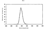

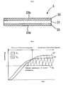

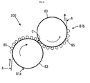
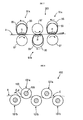

Classifications
-
- G—PHYSICS
- G03—PHOTOGRAPHY; CINEMATOGRAPHY; ANALOGOUS TECHNIQUES USING WAVES OTHER THAN OPTICAL WAVES; ELECTROGRAPHY; HOLOGRAPHY
- G03C—PHOTOSENSITIVE MATERIALS FOR PHOTOGRAPHIC PURPOSES; PHOTOGRAPHIC PROCESSES, e.g. CINE, X-RAY, COLOUR, STEREO-PHOTOGRAPHIC PROCESSES; AUXILIARY PROCESSES IN PHOTOGRAPHY
- G03C1/00—Photosensitive materials
- G03C1/494—Silver salt compositions other than silver halide emulsions; Photothermographic systems ; Thermographic systems using noble metal compounds
- G03C1/498—Photothermographic systems, e.g. dry silver
- G03C1/49881—Photothermographic systems, e.g. dry silver characterised by the process or the apparatus
-
- G—PHYSICS
- G03—PHOTOGRAPHY; CINEMATOGRAPHY; ANALOGOUS TECHNIQUES USING WAVES OTHER THAN OPTICAL WAVES; ELECTROGRAPHY; HOLOGRAPHY
- G03C—PHOTOSENSITIVE MATERIALS FOR PHOTOGRAPHIC PURPOSES; PHOTOGRAPHIC PROCESSES, e.g. CINE, X-RAY, COLOUR, STEREO-PHOTOGRAPHIC PROCESSES; AUXILIARY PROCESSES IN PHOTOGRAPHY
- G03C1/00—Photosensitive materials
- G03C1/494—Silver salt compositions other than silver halide emulsions; Photothermographic systems ; Thermographic systems using noble metal compounds
- G03C1/498—Photothermographic systems, e.g. dry silver
- G03C1/49836—Additives
- G03C1/49845—Active additives, e.g. toners, stabilisers, sensitisers
-
- G—PHYSICS
- G03—PHOTOGRAPHY; CINEMATOGRAPHY; ANALOGOUS TECHNIQUES USING WAVES OTHER THAN OPTICAL WAVES; ELECTROGRAPHY; HOLOGRAPHY
- G03C—PHOTOSENSITIVE MATERIALS FOR PHOTOGRAPHIC PURPOSES; PHOTOGRAPHIC PROCESSES, e.g. CINE, X-RAY, COLOUR, STEREO-PHOTOGRAPHIC PROCESSES; AUXILIARY PROCESSES IN PHOTOGRAPHY
- G03C1/00—Photosensitive materials
- G03C1/005—Silver halide emulsions; Preparation thereof; Physical treatment thereof; Incorporation of additives therein
- G03C1/0051—Tabular grain emulsions
-
- G—PHYSICS
- G03—PHOTOGRAPHY; CINEMATOGRAPHY; ANALOGOUS TECHNIQUES USING WAVES OTHER THAN OPTICAL WAVES; ELECTROGRAPHY; HOLOGRAPHY
- G03C—PHOTOSENSITIVE MATERIALS FOR PHOTOGRAPHIC PURPOSES; PHOTOGRAPHIC PROCESSES, e.g. CINE, X-RAY, COLOUR, STEREO-PHOTOGRAPHIC PROCESSES; AUXILIARY PROCESSES IN PHOTOGRAPHY
- G03C1/00—Photosensitive materials
- G03C1/005—Silver halide emulsions; Preparation thereof; Physical treatment thereof; Incorporation of additives therein
- G03C1/06—Silver halide emulsions; Preparation thereof; Physical treatment thereof; Incorporation of additives therein with non-macromolecular additives
- G03C1/061—Hydrazine compounds
-
- G—PHYSICS
- G03—PHOTOGRAPHY; CINEMATOGRAPHY; ANALOGOUS TECHNIQUES USING WAVES OTHER THAN OPTICAL WAVES; ELECTROGRAPHY; HOLOGRAPHY
- G03C—PHOTOSENSITIVE MATERIALS FOR PHOTOGRAPHIC PURPOSES; PHOTOGRAPHIC PROCESSES, e.g. CINE, X-RAY, COLOUR, STEREO-PHOTOGRAPHIC PROCESSES; AUXILIARY PROCESSES IN PHOTOGRAPHY
- G03C1/00—Photosensitive materials
- G03C1/494—Silver salt compositions other than silver halide emulsions; Photothermographic systems ; Thermographic systems using noble metal compounds
- G03C1/498—Photothermographic systems, e.g. dry silver
- G03C1/49818—Silver halides
-
- G—PHYSICS
- G03—PHOTOGRAPHY; CINEMATOGRAPHY; ANALOGOUS TECHNIQUES USING WAVES OTHER THAN OPTICAL WAVES; ELECTROGRAPHY; HOLOGRAPHY
- G03C—PHOTOSENSITIVE MATERIALS FOR PHOTOGRAPHIC PURPOSES; PHOTOGRAPHIC PROCESSES, e.g. CINE, X-RAY, COLOUR, STEREO-PHOTOGRAPHIC PROCESSES; AUXILIARY PROCESSES IN PHOTOGRAPHY
- G03C1/00—Photosensitive materials
- G03C1/494—Silver salt compositions other than silver halide emulsions; Photothermographic systems ; Thermographic systems using noble metal compounds
- G03C1/498—Photothermographic systems, e.g. dry silver
- G03C1/49827—Reducing agents
-
- G—PHYSICS
- G03—PHOTOGRAPHY; CINEMATOGRAPHY; ANALOGOUS TECHNIQUES USING WAVES OTHER THAN OPTICAL WAVES; ELECTROGRAPHY; HOLOGRAPHY
- G03C—PHOTOSENSITIVE MATERIALS FOR PHOTOGRAPHIC PURPOSES; PHOTOGRAPHIC PROCESSES, e.g. CINE, X-RAY, COLOUR, STEREO-PHOTOGRAPHIC PROCESSES; AUXILIARY PROCESSES IN PHOTOGRAPHY
- G03C11/00—Auxiliary processes in photography
- G03C11/02—Marking or applying text
-
- G—PHYSICS
- G03—PHOTOGRAPHY; CINEMATOGRAPHY; ANALOGOUS TECHNIQUES USING WAVES OTHER THAN OPTICAL WAVES; ELECTROGRAPHY; HOLOGRAPHY
- G03C—PHOTOSENSITIVE MATERIALS FOR PHOTOGRAPHIC PURPOSES; PHOTOGRAPHIC PROCESSES, e.g. CINE, X-RAY, COLOUR, STEREO-PHOTOGRAPHIC PROCESSES; AUXILIARY PROCESSES IN PHOTOGRAPHY
- G03C1/00—Photosensitive materials
- G03C1/005—Silver halide emulsions; Preparation thereof; Physical treatment thereof; Incorporation of additives therein
- G03C1/035—Silver halide emulsions; Preparation thereof; Physical treatment thereof; Incorporation of additives therein characterised by the crystal form or composition, e.g. mixed grain
- G03C2001/03558—Iodide content
-
- G—PHYSICS
- G03—PHOTOGRAPHY; CINEMATOGRAPHY; ANALOGOUS TECHNIQUES USING WAVES OTHER THAN OPTICAL WAVES; ELECTROGRAPHY; HOLOGRAPHY
- G03C—PHOTOSENSITIVE MATERIALS FOR PHOTOGRAPHIC PURPOSES; PHOTOGRAPHIC PROCESSES, e.g. CINE, X-RAY, COLOUR, STEREO-PHOTOGRAPHIC PROCESSES; AUXILIARY PROCESSES IN PHOTOGRAPHY
- G03C1/00—Photosensitive materials
- G03C1/005—Silver halide emulsions; Preparation thereof; Physical treatment thereof; Incorporation of additives therein
- G03C1/035—Silver halide emulsions; Preparation thereof; Physical treatment thereof; Incorporation of additives therein characterised by the crystal form or composition, e.g. mixed grain
- G03C2001/03594—Size of the grains
-
- G—PHYSICS
- G03—PHOTOGRAPHY; CINEMATOGRAPHY; ANALOGOUS TECHNIQUES USING WAVES OTHER THAN OPTICAL WAVES; ELECTROGRAPHY; HOLOGRAPHY
- G03C—PHOTOSENSITIVE MATERIALS FOR PHOTOGRAPHIC PURPOSES; PHOTOGRAPHIC PROCESSES, e.g. CINE, X-RAY, COLOUR, STEREO-PHOTOGRAPHIC PROCESSES; AUXILIARY PROCESSES IN PHOTOGRAPHY
- G03C1/00—Photosensitive materials
- G03C1/74—Applying photosensitive compositions to the base; Drying processes therefor
- G03C2001/7425—Coating on both sides
-
- G—PHYSICS
- G03—PHOTOGRAPHY; CINEMATOGRAPHY; ANALOGOUS TECHNIQUES USING WAVES OTHER THAN OPTICAL WAVES; ELECTROGRAPHY; HOLOGRAPHY
- G03C—PHOTOSENSITIVE MATERIALS FOR PHOTOGRAPHIC PURPOSES; PHOTOGRAPHIC PROCESSES, e.g. CINE, X-RAY, COLOUR, STEREO-PHOTOGRAPHIC PROCESSES; AUXILIARY PROCESSES IN PHOTOGRAPHY
- G03C2200/00—Details
- G03C2200/26—Gamma
-
- G—PHYSICS
- G03—PHOTOGRAPHY; CINEMATOGRAPHY; ANALOGOUS TECHNIQUES USING WAVES OTHER THAN OPTICAL WAVES; ELECTROGRAPHY; HOLOGRAPHY
- G03C—PHOTOSENSITIVE MATERIALS FOR PHOTOGRAPHIC PURPOSES; PHOTOGRAPHIC PROCESSES, e.g. CINE, X-RAY, COLOUR, STEREO-PHOTOGRAPHIC PROCESSES; AUXILIARY PROCESSES IN PHOTOGRAPHY
- G03C5/00—Photographic processes or agents therefor; Regeneration of such processing agents
- G03C5/16—X-ray, infrared, or ultraviolet ray processes
- G03C5/17—X-ray, infrared, or ultraviolet ray processes using screens to intensify X-ray images
-
- G—PHYSICS
- G03—PHOTOGRAPHY; CINEMATOGRAPHY; ANALOGOUS TECHNIQUES USING WAVES OTHER THAN OPTICAL WAVES; ELECTROGRAPHY; HOLOGRAPHY
- G03C—PHOTOSENSITIVE MATERIALS FOR PHOTOGRAPHIC PURPOSES; PHOTOGRAPHIC PROCESSES, e.g. CINE, X-RAY, COLOUR, STEREO-PHOTOGRAPHIC PROCESSES; AUXILIARY PROCESSES IN PHOTOGRAPHY
- G03C7/00—Multicolour photographic processes or agents therefor; Regeneration of such processing agents; Photosensitive materials for multicolour processes
- G03C7/30—Colour processes using colour-coupling substances; Materials therefor; Preparing or processing such materials
- G03C7/3041—Materials with specific sensitometric characteristics, e.g. gamma, density
Definitions
- the present invention relates to a photothermographic material and an image forming method. More particularly, the invention relates to a double-sided type photothermographic material using a silver halide emulsion with a high silver iodide content and an image forming method utilizing the same. Further, the invention relates to a double-sided type photothermographic material whose photographic property is improved and an image forming method utilizing the same.
- the photothermographic material has already been known.
- the photothermographic material has an image forming layer in which a photosensitive silver halide, a reducing agent, a reducible silver salt (for example, an organic silver salt), and if necessary, a toner for controlling the color tone of silver are dispersed in a binder.
- a photothermographic material forms a black silver image by being heated to a high temperature (for example, 80°C or higher) after imagewise exposure to cause an oxidation-reduction reaction between a silver halide or a reducible silver salt (functioning as an oxidizing agent) and a reducing agent.
- the oxidation-reduction reaction is accelerated by the catalytic action of a latent image on the silver halide generated by exposure. As a result, a black silver image is formed on the exposed region.
- a high temperature for example, 80°C or higher
- Silver iodide has the characteristic of causing less print-out than silver bromide or silver iodobromide having an iodide content of 5 mol% or less, and has a potential for fundamentally solving the problem
- the sensitivity of silver iodide grains known until now is extremely low, and the silver iodide grains do not achieve a level of sensitivity that is applicable for an actual system
- means of preventing recombination between photoelectrons and holes is performed to improve the sensitivity, it is an inherent problem that the characteristic of being excellent in the print-out property will be lost.
- photosensitive material for photographing means a photosensitive material on which images are recorded by a one-shot exposure through a lens, rather than by writing the image information by a scanning exposure with a laser beam or the like.
- photosensitive materials for photographing are generally known in the field of wet developing photosensitive materials, and include films for medical use such as direct or indirect radiography films, mammography films and the like, various kinds of photomechanical films used in printing, industrial recording films, films for photographing with general-purpose cameras, and the like.
- films for medical use such as direct or indirect radiography films, mammography films and the like, various kinds of photomechanical films used in printing, industrial recording films, films for photographing with general-purpose cameras, and the like.
- Photosensitive materials comprising tabular silver iodide grains as silver halide grains are well known in the wet developing field as described in JP-A Nos. 59-11934 and 59-119350, but there have been no examples of the application of the silver iodide grains in a photothermographic material. The reasons for this are because, as mentioned above, the sensitivity is very low, there are no effective sensitization means, and the technical barriers become even higher in thermal development.
- the photothermographic material In order to be used as this kind of photosensitive material for photographing, the photothermographic material needs higher sensitivity as well as an even higher level of image quality, such as the degree of haze of an obtained image.
- a first aspect of the invention is to provide a photothermographic material comprising, on both sides of a support, an image forming layer containing at least a photosensitive silver halide, a non-photosensitive organic silver salt, a reducing agent for silver ions, and a binder, wherein the image forming layer on a first side has an infectious development property, and the image forming layer on the other side does not have an infectious development property or has an infectious development property that is smaller than that of the image forming layer on the first side.
- a second aspect of the invention is to provide an image forming method using the photothermographic material according to the first aspect, wherein the method comprises: (a) providing an assembly for forming an image by placing the photothermographic material between a pair of fluorescent intensifying screens, (b) putting an analyte between the assembly and an X-ray source, (c) irradiating the analyte with X-rays having an energy level in a range of 25 kVp to 125 kVp, (d) taking the photothermographic material out of the assembly, and (e) thermally developing the thus taken out photothermographic material by a heating means in a temperature range of 90°C to 180°C.
- the photothermographic material of the present invention has, on the both sides of a support, an image forming layer comprising a photosensitive silver halide, a non-photosensitive organic silver salt, a reducing agent, and a binder.
- the photothermographic material may have a non-photosensitive layer such as an intermediate layer or a surface protective layer on the image forming layer.
- one of the image forming layers may be expressed as a front-side image forming layer, and the image forming layer on the other side may be expressed as a back-side image forming layer.
- the image forming layer on a first side has an infectious development property and the image forming layer on the other side does not have an infectious development property or has an infectious development property smaller than that of the image forming layer of the first side.
- the photographic properties of the image forming layers on two sides are different from each other.
- the photographic properties mentioned above include sensitivity, development proceeding property, hue angle of an image, gradation, and maximum image density (Dmax).
- “Infectious development” is one of the development mechanisms generally known for wet development system, for example, is explained in “KAITEI SYASHIN KOGAKU NO KISO -GINEN SHASHIN HEN" (The Basis of Photographic Technology -Silver Salt Photographic Science Section, revised edition), edited by the Society of Photographic Science and Technology of Japan, Corona Publishing Co., Ltd. (1998), pp. 339 to 341.
- "Infectious development” is a phenomenon in which a more powerful reducing product is generated by the oxidation product of a reducing agent generated by early development and accelerates the development.
- the developed silver is usually deposited in the region surrounding the latent image formed in the photosensitive silver halide grains.
- the image forming layer having the infectious development property of the present invention because the nuclei capable of depositing developed silvers are formed around the sites where no silver halide grains exist, the developed silvers, which is the same as developed silver around photosensitive silver halide grains, is deposited therein with proceeding of the development. Accordingly, whether a layer has an infectious development property or not, and its degree of infectious development property can be quantitatively confirmed in the following manner.
- the image portions after thermal development are observed by the electron micrographs thereof and then the observed developed silver grains are classified into those formed on the silver halide grains, or those formed on other sites.
- a layer having an infectious development property possesses numbers of developed silver grains in the maximum density area (Dmax part) more than the numbers of silver halide grains.
- an ultra thin section of a thickness of 0.1 ⁇ m is prepared by slicing the image forming layer of the undeveloped material in the direction parallel to the support using a diamond knife.
- the obtained ultra thin section is placed on a mesh and observed with a transmission electron microscope while cooled to a temperature of liquid nitrogen.
- the number (x) of silver halide grains per unit area is counted.
- an ultra thin section is prepared from the image forming layer in the maximum density portion of the exposed and thermal developed photothermographic materials of the present invention, and observed with a transmission electron microscope.
- the number (y) of developed silver grains per unit area is counted.
- a layer having an infectious development property has a ratio of y/x more than one, where y is the number of developed silver grains and x is the number of silver halide grains per unit area.
- the ratio of y/x is preferably from 2 to 80, and more preferably from 5 to 50.
- At least one of the front-side image forming layer and the back-side image forming layer has an infectious development property.
- the image forming layer on the other side does not have an infectious development property or a small infectious development property, and more preferably has an infectious development property smaller than that of the image forming layer of the first side.
- the ratio of y'/x' is preferably from 1 to 30, and more preferably from 1 to 10, where y' is the number of developed silver grains and x' is the number of silver halide grains per unit area of the image forming layer having a small infectious development property.
- the ratio of infectious development properties (y/x)/(y'/x') of the practice of the present invention is preferably from 1.2 to 80, and more preferably from 2 to 50, wherein y/x is obtained for the first side layer having an infectious development property of the invention and y'/x' is obtained for the other side layer having a small infectious development property.
- a photographic characteristic curve is a D-log E curve representing a relationship between the common logarithm (log E) of a light exposure, i.e., the exposure energy, and the optical density (D), i.e., a scattered light photographic density, by plotting the former on the abscissa and the latter on the ordinate.
- log E common logarithm
- D optical density
- a color tone of the image (in the present invention, sometimes expressed as a color tone of a developed silver image) can be determined from the evaluation by visual observation thereof, or by measurement of hue angles of each density portion.
- the photographic properties of both sides are measured as follows. Both sides of the material are subjected to simultaneous exposure for the same exposure time using an exposing device having double beam sources and then thermal development. Thereafter, the layer to be measured is prepared by removing the image forming layer on the opposite side from the processed material and measured by a densitometer to obtain a photographic characteristic curve. And also evaluation of a color tone of a developed silver image by visual observation and the measurements of hue angle in each density portion are performed.
- the front-side image forming layer and the back-side image forming layer of the photosensitive material may have different photographic properties from each other.
- the said different photographic properties can be obtained by the same equivalent heating means like as the practical heating means, or by the different heating means to result in giving the different photographic properties. Either way will be acceptable.
- Sensitivity in the present invention means a common logarithm of a reciprocal of the exposure value necessary for giving a density of fog+(optical density of 1.0) on the photographic characteristic curve.
- the difference in sensitivities between both sides of the material is preferably from 0.01 to 3.0, more preferably 0.05 to 2.0, and most preferably from 0.1 to 1.5.
- the image forming layer having a different sensitivity can be prepared by utilizing photosensitive silver halide grains and additives.
- sensitivity controlling means based on photosensitive silver halide grains include the difference in the grain size of the silver halide grain, the difference in the halide composition, the kind of chemical sensitizers and the level of sensitization, the kind and addition amount of spectral sensitizing dyes, and the difference in doping level by heavy metal ions.
- the additives to give a difference in sensitivity include the kind and addition amount of reducing agents, the kind and addition amount of antifoggants, the kind and addition amount of development accelerators, the kind and addition amount of color-tone adjusting agents, and the kind and addition amount of binders.
- Development proceeding property in the present invention means the difference in the maximum density (Dmax) obtained by thermal development at the time period for development of (the time period for a standard thermal development) ⁇ 2 seconds.
- the difference in development proceeding properties of the both sides in the practice of the present invention is preferably from 0.005 to 1, more preferably from 0.01 to 0.5, and most preferably from 0.05 to 0.3.
- the image forming layer having a different development proceeding property can be prepared by utilizing non-photosensitive organic silver salts and additives.
- non-photosensitive organic silver salts the composition (for example, a silver behenate content) and the grain shape of the organic silver salts are effective.
- the additives to provide a difference in development proceeding property include the kind and addition amount of reducing agents, the kind and addition amount of antifoggants, the kind and addition amount of development accelerators, the kind and addition amount of color-tone-adjusting agents, and the kind and addition amount of binders.
- Gradation in the present invention is expressed as a gradient of a line joining the points at fog+(optical density of 0.25) and fog+(optical density of 0.5) on the photographic characteristic curve (i.e., the value equals to tan when the angle between the line and the abscissa is).
- the difference in gradation of both sides is preferably from 0.005 to 0.3, more preferably from 0.01 to 2.5, and most preferably from 0.05 to 2.0.
- the image forming layer having a different gradation can be prepared by modifying the photosensitive silver halide emulsions, the non-photosensitive organic silver salts, and the additives.
- the following means are effective such like, as for the photosensitive silver halide emulsions, the shape and grain size distribution of the silver halide grains, the kind of chemical sensitizers and the level of sensitization, as for the organic silver salts, the shape and grain size distribution of the organic silver salts, and as for the additives, the kind and addition amount of reducing agents, the kind and addition amount of antifoggants, the kind and addition amount of development accelerators, the kind and addition amount of color-tone-adjusting agents, and the kind and addition amount of binders.
- Maximum density (Dmax) of the present invention is a density saturated with increasing the exposure value on the photographic characteristic curve.
- the difference in Dmax of both sides is preferably from 0.05 to 3.0, more preferably from 0.1 to 2.5, and most preferably from 0.2 to 2.0.
- the image forming layer having a different maximum density can be prepared by modifying the photosensitive silver halide emulsions, the non-photosensitive organic silver salts, and the additives.
- the following means are effective such as, as for the photosensitive silver halide emulsion, the shape, the grain size, the grain size distribution and coating amount of the silver halide grains, as for the organic silver salts, the shape, the grain size, the grain size distribution, and the coating amount of the organic silver salt, and as for the additives, the kind and addition amount of reducing agents, the kind and addition amount of antifoggants, the kind and addition amount of development accelerators, the kind and addition amount of color-tone adjusting agents, and the kind and addition amount of binders.
- a color tone of a developed silver image in the present invention is a value determined by visual observation of the silver image obtained by thermal development, or measurement of hue angles on each density portion set forth above.
- the difference in the color tone of a developed silver image of both sides is, expressed by the difference in hue angles for the portion of an optical density of 0.5, preferably in a range from 0.5° to 60°, more preferably from 1° to 50°, and most preferably from 5° to 40°.
- the image forming layer having a different color tone of a developed silver image can be prepared by modifying the non-photosensitive organic silver salts and the additives.
- the following means are effective for attaining the aim such as, for the non-photosensitive organic silver salts, the composition (for example, a silver behenate content) and the grain shape of the organic silver salts, and as for the additives, the kind and addition amount of reducing agents, the kind and addition amount of antifoggants, the kind and addition amount of development accelerators, the kind and addition amount of color-tone-adjusting agents, the kind and addition amount of binders.
- the infectious development property set forth above can be adjusted by various means.
- One of them is the incorporation of a nucleator into the image forming layer or the layer adjacent to the image forming layer.
- the other means is the incorporation of an infectious development reducing agent in the layer.
- the above means may be applied in combination.
- the combined use of a phosphoric acid compound may result in enhancing the infectious development property.
- the nucleator according to the invention is a compound, which can form a compound that can newly induce a development by the reaction with a developing product in consequence of an initial development. It was conventionally known to use a nucleator for the ultra-high contrast photosensitive materials suitable for the use in graphic arts.
- the ultra-high contrast photosensitive materials had an average gradient of ten or more and were unsuitable for conventional photographic materials, and especially unsuitable for the medical use where high diagnostic ability was required. And because the ultra-high contrast photosensitive material had rough graininess and did not have enough sharpness, there was no potential for medical diagnostic use.
- the nucleator in the present invention completely differs from the nucleator in the conventional ultra-high contrast photosensitive material as regards the effect.
- the nucleator in the present invention does not make a hard gradation.
- the nucleator in the present invention is the compound that can cause development sufficiently, even if the number of photosensitive silver halide grains with respect to non-photosensitive silver salt of an organic acid is extremely low. Although that mechanism is not clear, when thermal development is performed using the nucleator according to the present invention, it becomes clear that a large number of developed silver grains exists than the number of photosensitive silver halide grains in the maximum density part, and it is presumed that the nucleator according to the present invention forms the new development points (development nuclei) in those portions where silver halide grains do not exist.
- the covering power of the developed silver can be increased without causing deterioration of graininess.
- hydrazine derivative compounds represented by the following formula (H) vinyl compounds represented by the following formula (G), and quaternary onium compounds represented by the following formula (P), cyclic olefine compounds represented by formulae (A), (B), and (C) are preferable examples.
- a 0 represents one selected from an aliphatic group, an aromatic group, a heterocyclic group, and a -G 0 -D 0 group, each of which may have a substituent.
- B 0 represents a blocking group.
- a 1 and A 2 both represent a hydrogen atom, or one represents a hydrogen atom and the other represents one of an acyl group, a sulfonyl group, and an oxalyl group.
- G 1 represents one selected from a mere bonding hand, an -0- group, an -S- group, and an -N(D 1 )- group
- D 1 represents one selected from an aliphatic group, an aromatic group, a heterocyclic group, and a hydrogen atom. In the case where plural D 1 s exist in a molecule, they may be the same or different.
- D 0 represents one selected from a hydrogen atom, an aliphatic group, an aromatic group, a heterocyclic group, an amino group, an alkoxy group, an aryloxy group, an alkylthio group, and an arylthio group.
- a hydrogen atom, an alkyl group, an alkoxy group, an amino group and the like can be described.
- the aliphatic group represented by A 0 preferably has 1 to 30 carbon atoms, and particularly preferably is a normal, blanched or cyclic alkyl group having 1 to 20 carbon atoms.
- a methyl group, an ethyl group, a t-butyl group, an octyl group, a cyclohexyl group, and a benzyl group are described.
- a suitable substituent e.g., an aryl group, an alkoxy group, an aryloxy group, an alkylthio group, an arylthio group, a sulfoxy group, a sulfonamide group, a sulfamoyl group, an acylamino group, a ureido group and the like.
- the aromatic group represented by A 0 is preferably an aryl group of a single or condensed ring.
- a benzene ring or a naphthalene ring is described.
- a heterocycle represented by A 0 the heterocycle of a single or condensed ring containing at least one heteroatom selected from a nitrogen atom, a sulfur atom and an oxygen atom is preferable.
- a pyrrolidine ring, an imidazole ring, a tetrahydrofuran ring, a morpholine ring, a pyridine ring, a pyrimidine ring, a quinoline ring, a thiazole ring, a benzothiazole ring, a thiophene ring and a furan ring are described.
- the arotamic group, heterocyclic group or -G 0 -D 0 group, as A 0 may have a substituent.
- an aryl group or a -G 0 -D 0 group is particularly preferable.
- a 0 preferably contains at least one of a diffusion-resistant group or an adsorptive group to silver halide.
- a diffusion-resistance group a ballast group usually used as non-moving photographic additive is preferable.
- a ballast group a photochemically inactive alkyl group, alkenyl group, alkynyl group, alkoxy group, phenyl group, phenoxy group, alkylphenoxy group and the like are described and it is preferred that the substituent part has 8 or more carbon atoms in total.
- B 0 represents a blocking group and preferably a -G 0 -D 0 group.
- G 0 a -CO- group and a -COCO- group are described.
- G 1 represents one selected from a mere bonding hand, an -0- group, an -S- group, and an -N(D 1 )- group
- D 1 represents one selected from an aliphatic group, an aromatic group, a heterocyclic group, and a hydrogen atom
- D 0 represents one selected from a hydrogen atom, an aliphatic group, an aromatic group, a heterocyclic group, an amino group, an alkoxy group, an aryloxy group, an alkylthio group, and an arylthio group.
- a 1 and A 2 both represent a hydrogen atom, or one of A 1 and A 2 represents a hydrogen atom and the other represents one selected from an acyl group (an acetyl group, a trifluoroacetyl group, a benzoyl group or the like), a sulfonyl group (a methanesulfonyl group, a toluenesulfonyl group or the like), and an oxalyl group (an ethoxalyl group or the like).
- an acyl group an acetyl group, a trifluoroacetyl group, a benzoyl group or the like
- a sulfonyl group a methanesulfonyl group, a toluenesulfonyl group or the like
- an oxalyl group an ethoxalyl group or the like.
- the compounds represented by formula (H) can be easily synthesized by known methods. For example, these can be synthesized by referring to USP Nos. 5464738 and 5496695.
- hydrazine derivatives preferably used are the compound H-1 to H-29 described in USP No. 5545505, columns 11 to 20 and the compounds 1 to 12 described in USP No. 5464738, columns 9 to 11. These hydrazine derivatives can be synthesized by known methods.
- formula (G) is explained.
- X and R are displayed in a cis form
- a trans form for X and R is also included in formula (G). This is also similar to the structure display of specific compounds.
- X represents an electron-attracting group
- W represents one selected from a hydrogen atom, an alkyl group, an alkenyl group, an alkynyl group, an aryl group, a heterocyclic group, a halogen atom, an acyl group, a thioacyl group, an oxalyl group, an oxyoxalyl group, a thiooxalyl group, an oxamoyl group, an oxycarbonyl group, a thiocarbonyl group, a carbamoyl group, a thiocarbamoyl group, a sulfonyl group, a sulfinyl group, an oxysulfinyl group, a thiosulfinyl group, a sulfamoyl group, an oxysulfinyl group, a thiosulfinyl group, a sulfamoyl group, an
- R represents one selected from a halogen atom, a hydroxy group, an alkoxy group, an aryloxy group, a heterocyclic oxy group, an alkenyloxy group, an acyloxy group, an alkoxycarbonyloxy group, an aminocarbonyloxy group, a mercapto group, an alkylthio group, an arylthio group, a heterocyclic thio group, an alkenylthio group, an acylthio group, an alkoxycarbonylthio group, an aminocarbonylthio group, an organic or inorganic salt of hydroxy group or mercapto group (e.g., a sodium salt, a potassium salt, a silver salt, or the like), an amino group, an alkylamino group, a cyclic amino group (e.g., a pyrrolidino group), an acylamino group, an oxycarbonylamino group, a heterocyclic group (a 5 or 6-membered
- X and W, and X and R may bind each other to form a cyclic structure.
- X and W for example, pyrazolone, pyrazolidinone, cyclopentanedione, ⁇ -ketolactone, ⁇ -ketolactam, and the like are described.
- the electron-attracting group represented by X is a substituent which can have a positive value of substituent constant ⁇ p.
- a substituted alkyl group halogen substituted alkyl and the like
- a substituted alkenyl group cyanovinyl and the like
- a substituted or unsubstituted alkynyl group trifluoromethylacetylenyl, cyanoacetylenyl and the like
- a substituted aryl group cyanophenyl and the like
- a substituted or unsubstituted heterocyclic group pyridyl, triazinyl, benzooxazolyl and the like
- a halogen atom a cyano group
- an acyl group acetyl, trifluoroacetyl, formyl and the like
- a thioacetyl group thioacetyl, thioformyl and the like
- alkyl group represented by W methyl, ethyl, trifluoromethyl and the like are described.
- alkenyl group as W, vinyl, halogen substituted vinyl, cyanovinyl and the like are described.
- alkynyl group as W, acetylenyl, cyanoacetylenyl and the like are described.
- aryl group as W, nitrophenyl, cyanophenyl, pentafluorophenyl and the like are described, and as a heterocyclic group as W, pyridyl, pyrimidyl, triazinyl, succinimide, tetrazolyl, triazolyl, imidazolyl, benzooxazolyl and the like are described.
- W the electron-attracting group having a positive ⁇ p value is preferable, and that value is more preferably 0.30 or more.
- a hydroxy group, a mercapto group, an alkoxy group, an alkylthio group, a halogen atom, an organic or inorganic salt of hydroxy group or mercapto group, and a heterocyclic group are preferably described. More preferably, a hydroxy group, an alkoxy group, an organic or inorganic salt of hydroxy group or mercapto group and a heterocyclic group are described, and particularly preferably, a hydroxy group and an organic or inorganic salt of hydroxy group or mercapto group are described.
- Q represents a nitrogen atom or a phosphorus atom.
- R 1 , R 2 , R 3 , and R 4 each independently represent a hydrogen atom or a substituent, and X- represents an anion.
- R 1 to R 4 may link each other to form a ring.
- an alkyl group (a methyl group, an ethyl group, a propyl group, a butyl group, a hexyl group, a cyclohexyl group and the like), an alkenyl group (an allyl group, a butenyl group and the like), an alkynyl group (a propargyl group, a butynyl group and the like), an aryl group (a phenyl group, a naphthyl group and the like), a heterocyclic group (a piperidinyl group, a piperazinyl group, a morpholinyl group, a pyridyl group, a furyl group, a thienyl group, a tetrahydrofuryl group, a tetrahydrothienyl group, a sulforanyl group and the like), an amino group and the like are described.
- a piperidine ring As the ring formed by linking R 1 to R 4 each other, a piperidine ring, a morpholine ring, a piperazine ring, a quinuclidine ring, a pyridine ring, a pyrrole ring, an imidazole ring, a triazole ring, a tetrazole ring and the like are described.
- the group represented by R 1 to R 4 may have a substituent such as a hydroxy group, an alkoxy group, an aryloxy group, a carboxyl group, a sulfo group, an alkyl group, an aryl group, and the like.
- a substituent such as a hydroxy group, an alkoxy group, an aryloxy group, a carboxyl group, a sulfo group, an alkyl group, an aryl group, and the like.
- R 1 , R 2 , R 3 , and R 4 a hydrogen atom and an alkyl group are preferable.
- anion represented by X - an organic or inorganic anion such as a halogen ion, a sulfate ion, a nitrate ion, an acetate ion, a p-toluenesulfonate ion and the like are described.
- the quaternary onium compound described above can be synthesized by referring to known methods.
- the tetrazolium compound described above can be synthesized by referring to the method described in Chemical Reviews, vol. 55, pages 335 to 483.
- substituent examples of substituent are selected from the compounds listed below.
- a halogen atom fluorine atom, chlorine atom, bromine atom or iodine atom
- an alkyl group includes an aralkyl group, a cycloalkyl group and an active methine group
- an alkenyl group an alkynyl group, an aryl group, a heterocyclic group, a heterocyclic group containing a quaternary nitrogen (e.g., a pyridinio group)
- an acyl group an alkoxycarbonyl group, an aryloxycarbonyl group, a carbamoyl group, a carboxyl group or a salt thereof, a sulfonylcarbamoyl group, an acylcarbamoyl groyp, a sulfamoylcarbamoyl
- Y 3 represents a hydrogen atom or a substituent, and when Y 3 represents a substituent, following group is specifically described as that substituent. Namely, an alkyl group, an aryl group, a heterocyclic group, a cyano group, an acyl group, an alkoxycarbonyl group, an aryloxycarbonyl group, a carbamoyl group, an amino group, an alkylamino group, an arylamino group, a heterocyclic amino group, an acylamino group, a sulfonamide group, a ureido group, a thioureido group, an imide group, an alkoxy group, an aryloxy group, an alkylthio group, an arylthio group, a heterocyclic thio group, and the like are described. These substituents may be substituted by any substituents, and specifically, examples of the substituents which Z 1 or
- X 1 and X 2 each independently represent one selected from a hydroxy group (or a salt thereof), an alkoxy group (e.g., a methoxy group, an ethoxy group, a propoxy group, an isopropoxy group, an octyloxy group, a dodecyloxy group, a cetyloxy group, a t-butoxy group, or the like), an aryloxy group (e.g., a phenoxy group, a p-t-pentylphenoxy group, a p-t-octylphenoxy group, or the like), a heterocyclic oxy group (e.g., a benzotriazolyl-5-oxy group, a pyridinyl-3-oxy group, or the like), a mercapto group (or a salt thereof), an alkylthio group (e.g., methylthio group, an ethlythio group,
- a heterocyclic group is an aromatic or non-aromatic, a saturated or unsaturated, a single ring or condensed ring, or a substituted or unsubstituted heterocyclic group.
- a salt represents a salt of an alkali metal (sodium, potassium, or lithium), a salt of an alkali earth metal (magnesium or calcium), a silver salt, a quaternary ammonium salt (a tetraethylammonium salt, a dimethylcetylbenzylammonium salt, or the like), a quaternary phosphonium salt, or the like.
- X 1 represents one selected from an oxygen atom, a sulfur atom, and a nitrogen atom.
- the bond of X 1 and Z 1 may be either a single bond or a double bond, and in the case of a single bond, a nitrogen atom may have a hydrogen atom or any substituent.
- an alkyl group (includes an aralkyl group, a cycloalkyl group, an active methine group and the like), an alkenyl group, an alkynyl group, an aryl group, a heterocyclic group, an acyl group, an alkoxycarbonyl group, an aryloxycarbonyl group, a carbamoyl group, an alkylsulfonyl group, an arylsulfonyl group, a heterocyclic sulfonyl group, and the like are described.
- Z 1 represents a nonmetallic atomic group capable to form a 5 to 7-membered ring containing X 1 and Y 1 .
- the atomic group to form that ring is an atomic group which consists of 2 to 4 atoms that are other than metal atoms, and these atoms may be combined by single bond or double bond, and these may have a hydrogen atom or any subsituent (e.g., an alkyl group, an aryl group, a heterocyclic group, an alkoxy group, an alkylthio group, an acyl group, an amino group, or an alkenyl group).
- Z 1 forms a 5 to 7-membered ring containing X 1 and Y 1
- the ring is a saturated or unsaturated heterocycle, and may be a single ring or may have a condensed ring.
- R 1 , R 2 , R 3 , and R 4 each independently represent a hydrogen atom or a substituent. However, R 1 and R 2 never bind each other to form a ring structure.
- R 1 and R 2 represent a monovalent substituent
- the following groups are described as a monovalent substituent.
- a halogen atom fluorine atom, chlorine atom, bromine atom, or iodine atom
- an alkyl group including an aralkyl group, a cycloalkyl group, an active methine group, and the like
- an alkenyl group an alkynyl group, an aryl group, a heterocyclic group, a heterocyclic group containing a quaternary nitrogen atom (e.g., a pyridinio group)
- an acyl group an alkoxycarbonyl group, an aryloxycarbonyl group, a carbamoyl group, a carboxyl group and a salt thereof, a sulfonylcarbamoyl group, an acylcarbamoyl group, a sulfamoylcarbamoyl group, a carbazoyl group, an oxalyl group, an oxamoyl group, a
- R 3 and R 4 represent a substituent
- the same substituent as what R 1 and R 2 may have except the halogen atom can be described as the substituent.
- R 3 and R 4 may further link to Z 1 to form a condensed ring.
- Z 1 preferably is an atomic group which forms a 5 to 7-membered ring with X 1 and Y 1 , and consists of the atoms selected from 2 to 4 carbon atoms, a nitrogen atom, a sulfur atom, and an oxygen atom.
- a heterocycle, which is formed by Z 1 with X 1 and Y 1 preferably contains 3 to 40 carbon atoms in total, more preferably 3 to 25 carbon atoms in total, and most preferably 3 to 20 carbon atoms in total.
- Z 1 preferably comprises at least one carbon atom.
- the monovalent substituent represented by R 1 and R 2 is preferably one of the following groups having 0 to 25 carbon atoms in total, namely, those are an alkyl group, an aryl group, a heterocyclic group, an alkoxy group, an aryloxy group, a heterocyclic oxy group, an alkylthio group, an arylthio group, a heterocyclic thio group, an amino group, an alkylamino group, an arylamino group, a heterocyclic amino group, a ureido group, an imide group, an acylamino group, a hydroxy group and a salt thereof, a mercapto group and a salt thereof, and an electron-attracting group.
- an electron-attracting group means the substituent capable to have a positive value of Hammett substituent constant ⁇ p, and specifically a cyano group, a sulfamoyl group, an alkylsulfonyl group, an arylsulfonyl group, a sulfonamide group, an imino group, a nitro group, a halogen atom, an acyl group, a formyl group, a phosphoryl group, a carboxyl group (or a salt thereof), a sulfo group (or a salt thereof), a saturated or unsaturated heterocyclic group, an alkenyl group, an alkynyl group, an acyloxy group, an acylthio group, a sulfonyloxy group, and an aryl group substituted by these electron-attracting group are described. These substituents may have any substituents.
- R 1 and R 2 represent a monovalent substituent
- more preferable are an alkoxy group, an aryloxy group, a heterocyclic oxy group, an alkylthio group, an arylthio group, a heterocyclic thio group, an amino group, an alkylamino group, an arylamino group, a heterocyclic amino group, a ureido group, an imide group, an acylamino group, a sulfonamide group, a heterocyclic group, a hydroxy group or a salt thereof, a mercapto group or a salt thereof, and the like.
- R 1 and R 2 particularly preferably are a hydrogen atom, an alkoxy group, an aryloxy group, an alkylthio group, an arylthio group, a heterocyclic group, a hydroxy group or a salt thereof, a mercapto group or a salt thereof, or the like.
- one of R 1 and R 2 is a hydrogen atom and another is an alkoxy group, an aryloxy group, an alkylthio group, an arylthio group, a heterocyclic group, a hydroxy group or a salt thereof, or a mercapto group or a salt thereof.
- R 3 when R 3 represents a substituent, R 3 is preferably an alkyl group having 1 to 25 carbon atoms in total (including an aralkyl group, a cycloalkyl group, an active methine group and the like), an alkenyl group, aryl group, a heterocyclic group, a heterocyclic group containing a quaternary nitrogen (e.g., a pyridinio group), an acyl group, an alkoxycarbonyl group, an aryloxycarbonyl group, a carbamoyl group, an alkylsulfonyl group, an arylsulfonyl group, an alkylsulfinyl group, an arylsulfinyl group, a sulfosulfamoyl group, an alkoxy group, an aryloxy group, a heterocyclic oxy group, an alkylthio group, an arylthio group, a heterocyclic oxy
- R 4 when R 4 represents a substituent, R 4 is preferably an alkyl group (including an aralkyl group, a cycloalkyl group, an active methine group, and the like) having 1 to 25 carbon atoms in total, an aryl group, a heterocyclic group, a heterocyclic group containing a quaternary nitrogen atom (e.g., a pyridinio group), an acyl group, an alkoxycarbonyl group, an aryloxycarbonyl group, a carbamoyl group, an alkylsulfonyl group, an arylsulfonyl group, an alkylsulfinyl group, an arylsulfinyl group, a sulfosulfamoyl group, an alkoxy group, an aryloxy group, a heterocyclic oxy group, an alkylthio group, an arylthio group, a heterocyclic thio group
- an alkyl group, an aryl group, an alkoxy group, an aryloxy group, a heterocyclic oxy group, an alkylthio group, an arylthio group, a heterocyclic thio group, and the like are described.
- the carbon atom in Y 1 binds with the carbon atom substituted by X 1 or Y 1 .
- the addition amount of the above nucleator is in a range of 10 -5 mol to 1 mol per 1 mol of organic silver salt, and preferably, in a range of 10 -4 mol to 5 ⁇ 10 -1 mol.
- the nucleator described above may be incorporated into photothermographic material by being added into the coating solution, such as in the form of a solution, an emulsion dispersion, a solid fine particle dispersion, or the like.
- emulsion dispersing method there can be mentioned a method comprising dissolving the nucleator in an oil such as dibutylphthalate, tricresylphosphate, dioctylsebacate, tri(2-ethylhexyl)phosphate, or the like, and an auxiliary solvent such as ethyl acetate, cyclohexanone, or the like, and then adding a surfactant such as sodium dodecylbenzenesulfonate, sodium oleil-N-methyltaurinate, sodium di(2-thylhexyl)sulfosuccinate or the like; from which an emulsion dispersion is mechanically produced.
- an oil such as dibutylphthalate, tricresylphosphate, dioctylsebacate, tri(2-ethylhexyl)phosphate, or the like
- a surfactant such as sodium dodecylbenzenesulfonate
- solid particle dispersing method there can be mentioned a method comprising dispersing the powder of the nucleator in a proper solvent such as water or the like, by means of ball mill, colloid mill, vibrating ball mill, sand mill, jet mill, roller mill, or ultrasonics, thereby obtaining solid dispersion.
- a protective colloid such as polyvinyl alcohol
- a surfactant for instance, an anionic surfactant such as sodium triisopropylnaphthalenesulfonate (a mixture of compounds having the three isopropyl groups in different substitution sites)).
- the dispersion media In the mills enumerated above, generally used as the dispersion media are beads made of zirconia and the like, and Zr and the like eluting from the beads may be incorporated in the dispersion. Although depending on the dispersing conditions, the amount of Zr and the like generally incorporated in the dispersion is in a range of from 1 ppm to 1000 ppm. It is practically acceptable so long as Zr is incorporated in an amount of 0.5 mg or less per 1 g of silver.
- an antiseptic for instance, benzisothiazolinone sodium salt
- an antiseptic for instance, benzisothiazolinone sodium salt
- the nucleator is particularly preferably used as solid particle dispersion, and is added in the form of fine particles having average particle size from 0.01 ⁇ m to 10 ⁇ m preferably from 0.05 ⁇ m to 5 ⁇ m and, more preferably from 0.1 ⁇ m to 2 ⁇ m In the invention, other solid dispersions are preferably used with this particle size range.
- the compound represented by formulae (H) or (P) is used preferably, and the compound represented by formula (H) is used particularly preferably, among the nucleators described above.
- the compound represented by formulae (G), (A), (B), or (C) is used preferably, and the compound represented by formulae (A) or (B) is particularly preferably used.
- the compound represented by formula (C) is preferably used.
- the nucleator of the present invention can be added to the image forming layer or the layer adjacent to the image forming layer, however, it is preferably added to the image forming layer.
- the addition amount of nucleator is in a range of 10 -5 mol to 1 mol per 1 mol of organic silver salt, and preferably, in a range of 10 -4 mol to 5 x 10 -1 mol.
- the nucleator may be added either only one kind or, two or more kinds in combination.
- infectious development reducing agent used in the present invention, any infectious reducing agent may be used.
- a preferable infectious development reducing agent used in the present invention is the compound represented by the following formula (R1).
- R 11 and R 11' each independently represent a secondary or tertiary alkyl group having 3 to 20 carbon atoms.
- R 12 and R 12' each independently represent a hydrogen atom or a group being connected through a nitrogen, oxygen, phosphorus, or sulfur atom.
- R 13 represents a hydrogen atom or an alkyl group having 1 to 20 carbon atoms.
- R 11 and R 11' described above a secondary or tertiary alkyl group having 3 to 12 carbon atoms is preferable.
- an isopropyl group, a tert-butyl group, a tert-amyl group, a 1,1-dimethylpropyl group, a 1,1-dimethylbutyl group, a 1,1-dimethylhexyl group, a 1,1,3,3-tetramethylbutyl group, a 1,1-dimethyldecyl group, a 1-methylcyclohexyl group, a tert-octyl group, a 1-methylcyclopropyl group, and the like are preferable, and a tert-butyl group, a tert-amyl group, a tert-octyl group, and a 1-methylcyclohexyl group are more preferable, and a tert-butyl
- R 12 and R 12' are an aryloxy group, an arylthio grpoup, an anilino group, a heterocyclic group, or a heterocyclic thio group
- these group may have a substituent.
- substituent although any group may be possible as far as it is capable of substituting for a hydrogen atom on a benzene ring or a heterocycle, and, an alkyl group, an aryl group, a heterocyclic group, a halogen atom, an alkoxy group, a hydroxy group, an aryloxy group, an alkylthio group, an arylthio group, an amino group, an acyl group, an acyloxy group, an acylamino group, an alkoxycarbonyl group, a carbamoyl group, a sulfonyl group, a sulfonamide group, a sulfonyloxy group, a sulfamoyl
- R 12 and R 12' are an alkoxy group, a carbonyloxy group, an acyloxy group, an alkylthio group, an amino group, an acylamino group, a ureido group or a urethane group
- these groups may further have a substituent and as examples of the said substituent, an alkoxy group, an alkoxycarbonyl group, an acyloxy group, an sulfonyl group, a carbonyl group, an alkylthio group, an aryloxy group, an arylthio group, a sulfonamide group, an acylamino group, and the like are described.
- a hydrogen atom, a hydroxy group, an amino group, and an anilino group are more preferable, and further, a hydrogen atom, a methoxy group, or a benzyloxy group is most preferable.
- a hydrogen atom or an alkyl group having 1 to 15 carbon atoms is preferable, and an alkyl group having 1 to 8 carbon atoms is more preferable.
- a methyl group, an ethyl group, a propyl group, an isopropyl group, or a 2,4,4-trimethylpenthyl group is preferable.
- a hydrogen atom, a methyl group, an ethyl group, a propyl group, or an isopropyl group is particularly preferable.
- the addition amount of the reducing agent represented by the above-described formula (R1) is preferably from 0.01 g/m 2 to 5.0 g/m 2 , and more preferably from 0.1 g/m 2 to 3.0 g/m 2 . It is preferably contained in the range from 5 mol% to 50 mol% and, more preferably, 10 mol% to 40 mol%, per 1 mol of silver in the image forming layer.
- the reducing agent represented by the above-described formula (R1) is preferably contained in the image forming layer.
- reducing agents may be used in combination with the reducing agent represented by formula (R1).
- the reducing agent which can be used in combination may be any substance (preferably, organic substance) capable of reducing silver ions into metallic silver. Examples of the reducing agent are described in JP-A No. 11-65021 (column Nos. 0043 to 0045) and European Patent (EP) No. 0803764 (p.7, line 34 to p. 18, line 12).
- the reducing agent which can be used in combination is preferably a so-called hindered phenolic reducing agent or a bisphenol agent having a substituent at the ortho-position to the phenolic hydroxy group.
- the ratio of combination by mole is 1/99 to 99/1, and preferably 5/95 to 95/5.
- the reducing agent of the invention can be added in the image forming layer which comprises an organic silver salt and a photosensitive silver halide, or in the layer adjacent to the image forming layer, but it is preferably contained in the image forming layer.
- the reducing agent of the invention may be incorporated into photothermographic material by being added into the coating solution, such as in the form of a solution, an emulsion dispersion, a solid fine particle dispersion, or the like.
- emulsion dispersing method there can be mentioned a method comprising dissolving the reducing agent in an oil such as dibutylphthalate, tricresylphosphate, glyceryl triacetate, diethylphthalate, or the like, and an auxiliary solvent such as ethyl acetate, cyclohexanone, or the like, followed by mechanically forming an emulsified dispersion.
- an oil such as dibutylphthalate, tricresylphosphate, glyceryl triacetate, diethylphthalate, or the like
- an auxiliary solvent such as ethyl acetate, cyclohexanone, or the like
- solid fine particle dispersing method there can be mentioned a method comprising dispersing the reducing agent in a proper solvent such as water or the like, by means of ball mill, colloid mill, vibrating ball mill, sand mill, jet mill, roller mill, or ultrasonics, thereby obtaining solid dispersion.
- a dispersing method using a sand mill is preferable.
- a protective colloid such as polyvinyl alcohol
- a surfactant for instance, an anionic surfactant such as sodium triisopropylnaphthalenesulfonate (a mixture of compounds having the three isopropyl groups in different substitution sites)
- An antiseptic for instance, benzisothiazolinone sodium salt
- benzisothiazolinone sodium salt can be added in the water dispersion.
- the reducing agent is particularly preferably used as a solid particle dispersion, and the reducing agent is added in the form of fine particles having average particle size from 0.01 ⁇ m to 10 ⁇ m, more preferably, from 0.05 ⁇ m to 5 ⁇ m and, further preferably, from 0.1 ⁇ m to 1 ⁇ m.
- the photothermographic material of the invention preferably contains a reducing agent for organic silver salts.
- the reducing agent may be any substance (preferably, organic substance) capable of reducing silver ions into metallic silver. Examples of the reducing agent are described in JP-A No. 11-65021 (column Nos. 0043 to 0045) and EP No. 0803764A1 (page 7, line 34 to page 18, line 12).
- preferable reducing agent is the compound represented by the following formula (R).
- R 11 and R 11' each independently represent an alkyl group having 1 to 20 carbon atoms.
- R 12 and R 12' each independently represent a hydrogen atom or a group capable of substituting for a hydrogen atom on a benzene ring.
- L represents an -S-group or a -CHR 13 - group.
- R 13 represents a hydrogen atom or an alkyl group having 1 to 20 carbon atoms.
- X 1 and X 1' each independently represent a hydrogen atom or a group capable of substituting for a hydrogen atom on a benzene ring.
- R 11 and R 11' each independently represent a substituted or unsubstituted alkyl group having 1 to 20 carbon atoms.
- the substituent for the alkyl group has no particular restriction and can include, preferably, an aryl group, a hydroxy group, an alkoxy group, an aryloxy group, an alkylthio group, an arylthio group, an acylamino group, a sulfonamide group, a sulfonyl group, a phosphoryl group, an acyl group, a carbamoyl group, an ester group, a ureido group, a urethane group, a halogen atom, and the like.
- R 12 and R 12' each independently represent a hydrogen atom or a group capable of substituting for a hydrogen atom on a benzene ring.
- X 1 and X 1' each independently represent a hydrogen atom or a group capable of substituting for a hydrogen atom on a benzene ring.
- groups capable of substituting for a hydrogen atom on the benzene ring an alkyl group, an aryl group, a halogen atom, an alkoxy group, and an acylamino group are described preferably.
- L represents an -S- group or a -CHR 13 - group.
- R 13 represents a hydrogen atom or an alkyl group having 1 to 20 carbon atoms in which the alkyl group may have a substituent.
- unsubstituted alkyl group for R 13 can include, for example, a methyl group, an ethyl group, a propyl group, a butyl group, a heptyl group, an undecyl group, an isopropyl group, a 1-ethylpentyl group, a 2,4,4-trimethylpentyl group, and the like.
- Examples of the substituent for the alkyl group can include, similar to substituent of R 11 , a halogen atom, an alkoxy group, an alkylthio group, an aryloxy group, an arylthio group, an acylamino group, a sulfonamide group, a sulfonyl group, a phosphoryl group, an oxycarbonyl group, a carbamoyl group, a sulfamoyl group, and the like.
- R 11 and R 11' are preferably a secondary or tertiary alkyl group having 3 to 15 carbon atoms. Specifically, an isopropyl group, an isobutyl group, a t-butyl group, a t-amyl group, a t-octyl group, a cyclohexyl group, a cyclopentyl group, a 1-methylcyclohexyl group, a 1-methylcyclopropyl group, and the like can be described.
- R 11 and R 11' are, more preferably, a tertiary alkyl group having 4 to 12 carbon atoms and, among them, a t-butyl group, a t-amyl group, and a 1-methylcyclohexyl group are further preferred and, a t-butyl group is most preferred.
- R 12 and R 12' are preferably an alkyl group having 1 to 20 carbon atoms and can include, specifically, a methyl group, an ethyl group, a propyl group, a butyl group, an isopropyl group, a t-butyl group, a t-amyl group, a cyclohexyl group, a 1-methylcyclohexyl group, a benzyl group, a methoxymethyl group, a methoxyethyl group, and the like. More preferred are methyl group, ethyl group, propyl group, isopropyl group, and t-butyl group.
- X 1 and X 1' are preferably a hydrogen atom, a halogen atom, or an alkyl group, and more preferably, a hydrogen atom.
- L is preferably a -CHR 13 -group.
- R 13 is preferably a hydrogen atom or an alkyl group having 1 to 15 carbon atoms.
- the alkyl group can include a methyl group, an ethyl group, a propyl group, an isopropyl group, and a 2,4,4-trimethylpentyl group.
- Particularly preferable R 13 is a hydrogen atom, a methyl group, a propyl group, or an isopropyl group.
- R 12 and R 12' are preferably an alkyl group having 2 to 5 carbon atoms, more preferably an ethyl group or a propyl group, and most preferably an ethyl group.
- R 12 and R 12' are preferably a methyl group.
- the primary or secondary alkyl group having 1 to 8 carbon atoms as R 13 is preferably a methyl group, an ethyl group, a propyl group, or an isopropyl group, and more preferably a methyl group, an ethyl group, or a propyl group.
- R 13 is preferably a secondary alkyl group.
- the secondary alkyl group as R 13 is preferably an isopropyl group, an isobutyl group, or a 1-ethylpentyl group, and more preferably an isopropyl group.
- the above reducing agent has different thermal development properties depending on the combination of R 11 , R 11' , R 12 , R 12' , and R 13 . Since these properties can be controlled by using two or more kinds of the reducing agents in combination in various mixing ratios, it is preferable to use two or more kinds of the reducing agents depending on the purpose.
- the addition amount of the reducing agent is preferably in a range from 0.01 g/m 2 to 5.0 g/m 2 , and more preferably, from 0.1 g/m 2 to 3.0 g/m 2 . It is preferably contained in a range from 5 mol% to 50 mol%, and more preferably from 10 mol% to 40 mol%, per 1 mol of silver in the image forming layer.
- the reducing agent of the invention can be added in the image forming layer which comprises an organic silver salt and a photosensitive silver halide, or in the layer adjacent to the image forming layer, but it is preferably contained in the image forming layer.
- the reducing agent may be incorporated into photothermographic material by being added into the coating solution in a form and by an adding method similar to those in the aforementioned infectious development reducing agent.
- the photosensitive silver halide used in the present invention is preferably a tabular grain which has a silver iodide content of 40 mol% or higher. More preferably, the photosensitive silver halide grain in the present invention has a mean equivalent spherical diameter of 0.2 ⁇ m to 10.0 ⁇ m and 50% or more of the projected area of the photosensitive silver halide is occupied by tabular grains having an aspect ratio of 2 or more, and further preferably, has a mean equivalent spherical diameter of 0.3 ⁇ m to 5 ⁇ m and 50% or more of the projected area of the photosensitive silver halide is occupied by the tabular grains having an aspect ratio of 3 to 100.
- the photosensitive silver halide used in the present invention preferably has a silver iodide content of 40 mol% or higher.
- Other components are not particularly limited and can be selected from silver chloride, silver bromide, and organic silver salts such as silver phosphate and the like.
- the silver iodide content is 80 mol% or higher, and it is extremely preferable from the standpoint of image storability against irradiation with light after a developing process particularly when the silver iodide content is 90 mol% or higher.
- the distribution of the halogen composition in a grain may be uniform or the halogen composition may be changed stepwise, or it may be changed continuously.
- a silver halide grain having a core/shell structure can be preferably used.
- Preferred structure is a twofold to fivefold structure and, more preferably, core/shell grain having a twofold to fourfold structure can be used.
- a core-high-silver iodide-structure which has a high content of silver iodide in the core part, and a shell-high-silver iodide-structure which has a high content of silver iodide in the shell part can also be preferably used.
- Silver iodide of the invention typically can assume either a ⁇ phase or a ⁇ phase.
- ⁇ phase means a high silver iodide structure having a wurtzite structure of a hexagonal system and the term " ⁇ phase” means a high silver iodide structure having a zinc blende structure of a cubic crystal system.
- An average content of ⁇ phase in the present invention is determined by a method presented by C. R. Berry. In the method, an average content of ⁇ phase is calculated from the peak ratio of the intensity owing to ⁇ phase (111) to that owing to ⁇ phases (100), (101), and (002) in powder X ray diffraction method. Detail description, for example, is described in Physical Review, volume 161, No. 3, p. 848 to 851 (1967).
- the tabular grains according to the invention preferably have a mean equivalent spherical diameter of 0.2 ⁇ m to 10.0 ⁇ m, more preferably 0.3 ⁇ m to 5.0 ⁇ m, and most preferably 0.5 ⁇ m to 3.0 ⁇ m.
- Equivalent spherical diameter used here means a diameter of a sphere having the same volume as the volume of silver halide grain.
- the volume of a grain is calculated from projected area and thickness of individual grains by observation through electron microscope, and thereafter the equivalent spherical diameter is determined by converting the volume to a sphere having the volume equivalent to the obtained volume.
- the silver halide having high silver iodide content of the invention can take a complicated form, and as the preferable form, there are listed, for example, connecting grains as shown in R. L. JENKINS et al., J. of Phot. Sci., vol. 28 (1980), p164, Fig. 1. Tabular grains as shown in Fig. 1 of the same literature can also be preferably used. Silver halide grains which are rounded at corners can also be used preferably.
- the surface indices (Miller indices) of the outer surface of a photosensitive silver halide grain is not particularly restricted, and it is preferable that the ratio occupied by the [100] face is large, because of showing high spectral sensitization efficiency when a spectral sensitizing dye is adsorbed.
- the ratio is preferably 50% or more, more preferably 65% or more and, further preferably 80% or more.
- the ratio of the [100] face, Miller index can be determined by a method described in T. Tani; J. Imaging Sci., vol. 29, page 165, (1985) utilizing adsorption dependency of the [111] face and [100] face in adsorption of a sensitizing dye.
- the silver halide grain according to the invention is preferably a tabular grain.
- the photosensitive silver halide used in the present invention is obtained by adhering silver halide by means of epitaxial growth onto tabular silver halide grain having an aspect ratio of 2 to 100.
- 50% or more of a projected area of the silver halide is preferably occupied by tabular grains having an aspect ratio of 3 to 100, and more preferably, tabular grains having an aspect ratio of 5 to 50.
- the mean grain thickness is preferably 0.005 ⁇ m to 0.40 ⁇ m, more preferably 0.01 ⁇ m to 0.30 ⁇ m, and most preferably 0.03 ⁇ m to 0.20 ⁇ m
- epitaxy or “epitaxial” is used in the art as the term to indicate that the silver salt has a crystal form having an orientation controlled by tabular host grains.
- the sensitized sites on a tabular host grain silver salts formed with epitaxial growth can be applied. By controlling the sites deposited by the epitaxial growth, a selective local sensitization on tabular host grain can be performed. Accordingly, at one or more regular portions, the sensitization sites can be formed.
- the "regular" means that the sensitization sites have a predictable and orderly relations, preferably mutually, to the major crystal faces of the tabular grains. By controlling the epitaxial deposition to the major crystal faces of the tabular grains, it is possible to control the number and the space between the horizontal direction of the sensitization sites.
- tabular host grain On at least one part of the major crystal faces of tabular host grain, it is preferred to control silver salt epitaxy, and substantially to exclude the epitaxial deposition.
- an epitaxial deposition of silver salt tend to be formed at an edge portion and/or a corner portion of grains.
- the sensitivity is increased, in comparison with randomly epitaxial growth deposition of silver salts on the major crystal faces of tabular grains.
- substantially no epitaxial deposition of silver salts is formed, and for a selected site, the silver salts is deposited in a limited range.
- the above range of the deposition can be changed extensively within the scope of this invention.
- the lesser the epitaxial coverage on the major crystal faces the more the sensitivity increases.
- Silver salts formed by the epitaxial growth are preferably within less than a half, more preferably 25% or less, of the area of the major crystal faces of tabular grains.
- the silver salts are formed by epitaxial growth on the corner portion of tabular silver halide grain, they are preferably restricted within less than 10%, more preferably less than 5%, of the area of the major crystal faces. In some embodiments, it is observed that the epitaxial deposition is initiated at the site of the edge surface of tabular grains. Accordingly, depending on the condition, the epitaxy is restricted to a selected area of the edge portion, and the epitaxial deposition on the major crystal faces is effectively excluded.
- the sites and numbers of the latent image center can not determined.
- partially developed grains can be observed with a magnification and also partially developed sites can be clearly determined. These sites correspond generally to the latent image center, and generally these latent image centers correspond to the sensitized sites.
- Silver salt formed by epitaxy can be selected from arbitrary silver salts which are generally capable of epitaxial growth on silver halide grains, and known in the art as useful for photographic use. Especially, the silver salts are preferably selected from those known in the photographic art as effective for shell formation in core-shell type-silver halide grains.
- examples of preferred silver salts which are known to deposit on silver halide grains, include silver cyanate, silver carbonate, silver ferricyanate, silver arsenate, silver arsenite, and silver chromate, and mixtures thereof. Among them, preferred are silver chloride, silver bromide, silver thiocyanate, and mixtures thereof. Especially, at least silver bromide is preferably included.
- the silver salts can be adhered effectively in the presence of a modifying agent to the tabular silver halide grains.
- the iodide can extrude the silver epitaxy.
- the host grains can contain any anion other than iodide ion, up to the limit of the solubility into silver iodide.
- the silver halide grain used in the present invention preferably has one or more dislocation lines. More preferably the silver halide grain has 5 or more dislocation lines, and most preferably 10 or more dislocation lines.
- a total projected area of silver halide grains is occupied by tabular grains having one or more dislocation lines.
- 80% or more of the total projected area is preferably occupied by silver halide grains having 10 or more dislocation lines.
- dislocation line of silver halide crystals Concerning the dislocation line of silver halide crystals, the following references indicate that a dislocation line existing in the crystal can be observed by a method using an X-ray diffraction analysis or a transmission electron microscope, and various types of dislocations may be formed in the crystal by stressing the crystal.
- JP-A Nos. 63-220238 and 1-201649 disclose tabular silver halide grains having dislocations formed intentionally.
- the tabular grains having formed dislocations exhibit an excellent photographic property such as sensitivity and reciprocity failure compared with tabular grains having no dislocations.
- Photosensitive materials using the above tabular silver halide grains having dislocations are excellent in sharpness and granularity.
- dislocation lines are formed irregularly on the edge portion of the tabular grains, and the numbers of dislocation lines are different for individual grains.
- the coating amount of the silver halide is preferably from 0.5 mol% to 100 mol% per 1 mol of silver contained in the non-photosensitive organic silver salt, and more preferably from 5 mol% to 50 mol%.
- the method of forming photosensitive silver halide is well-known in the relevant art and, for example, methods described in Research Disclosure No. 17029, June 1978 and USP No. 3700458 can be used. Specifically, a method of preparing a photosensitive silver halide by adding a silver-supplying compound and a halogen-supplying compound in a gelatin or other polymer solution and then mixing them with an organic silver salt is used. Further, a method described in JP-A No. 11-119374 (paragraph Nos. 0217 to 0224) and methods described in JP-A Nos. 11-352627 and 2000-347335 are also preferred.
- the photosensitive silver halide grain of the invention can contain metals or complexes of metals belonging to groups 6 to 12 of the periodic table.
- the metal or the center metal of the metal complex from groups 6 to 12 of the periodic table is preferably rhodium, ruthenium, or iridium.
- the metal complex may be used alone, or two or more kinds of complexes comprising identical or different species of metals may be used together.
- the content is preferably in a range from 1 ⁇ 10 -9 mol to 1 ⁇ 10 -3 mol, per 1 mol of silver.
- the heavy metals, metal complexes and the addition method thereof are described in JP-A No. 7-225449, in paragraph Nos. 0018 to 0024 of JP-A No.11-65021, and in paragraph Nos. 0227 to 0240 of JP-A No.11-119374.
- a silver halide grain having a hexacyano metal complex present on the outermost surface of the grain is preferred.
- the hexacyano metal complex includes, for example, [Fe(CN) 6 ] 4- , [Fe(CN) 6 ] 3- , [Ru(CN) 6 ] 4- , [Os(CN)6] 4- , [CO(CN) 6 ] 3- , [Rh(CN) 6 ] 3- , [Ir(CN) 6 ] 3- , [Cr(CN) 6 ] 3- , and [Re(CN) 6 ] 3- .
- hexacyano Fe complex is preferred.
- alkali metal ion such as sodium ion, potassium ion, rubidium ion, cesium ion, and lithium ion, ammonium ion, and alkyl ammonium ion (for example, tetramethyl ammonium ion, tetraethyl ammonium ion, tetrapropyl ammonium ion, and tetra(n-butyl) ammonium ion
- alkyl ammonium ion for example, tetramethyl ammonium ion, tetraethyl ammonium ion, tetrapropyl ammonium ion, and tetra(n-butyl) ammonium ion
- the hexacyano metal complex can be added while being mixed with water, as well as a mixed solvent of water and an appropriate organic solvent miscible with water (for example, alcohols, ethers, glycols, ketones, esters, amides, or the like) or gelatin.
- a mixed solvent of water and an appropriate organic solvent miscible with water for example, alcohols, ethers, glycols, ketones, esters, amides, or the like
- gelatin for example, alcohols, ethers, glycols, ketones, esters, amides, or the like
- the addition amount of the hexacyano metal complex is preferably from 1 ⁇ 10 -5 mol to 1 ⁇ 10 -2 mol and, more preferably, from 1 ⁇ 10 -4 mol to 1 ⁇ 10 -3 , per 1 mol of silver in each case.
- the hexacyano metal complex is directly added in any stage of: after completion of addition of an aqueous solution of silver nitrate used for grain formation, before completion of emulsion formation step prior to a chemical sensitization step, of conducting chalcogen sensitization such as sulfur sensitization, selenium sensitization, and tellurium sensitization or noble metal sensitization such as gold sensitization, during a washing step, during a dispersion step and before a chemical sensitization step.
- the hexacyano metal complex is rapidly added preferably after the grain is formed, and it is preferably added before completion of the emulsion formation step.
- Addition of the hexacyano complex may be started after addition of 96% by weight of an entire amount of silver nitrate to be added for grain formation, more preferably started after addition of 98% by weight and, particularly preferably, started after addition of 99% by weight.
- any of the hexacyano metal complex When any of the hexacyano metal complex is added after addition of an aqueous silver nitrate just before completion of grain formation, it can be adsorbed to the outermost surface of the silver halide grain and most of them form an insoluble salt with silver ions on the surface of the grain. Since silver salt of hexacyano iron (II) is a less soluble salt than AgI, re-dissolution with fine grains can be prevented and fine silver halide grains with smaller grain size can be prepared.
- II hexacyano iron
- Metal atoms that can be contained in the silver halide grain used in the invention for example, [Fe(CN) 6 ] 4- ), desalting method of a silver halide emulsion and chemical sensitizing method are described in paragraph Nos. 0046 to 0050 of JP-A No. 11-84574, in paragraph Nos. 0025 to 0031 of JP-A No. 11-65021, and paragraph Nos. 0242 to 0250 of JP-A No. 11-119374.
- gelatin contained in the photosensitive silver halide emulsion used in the invention various kinds of gelatins can be used. It is necessary to maintain an excellent dispersion state of a photosensitive silver halide emulsion in a coating solution containing an organic silver salt, and gelatin having a low molecular weight of 500 to 60,000 is preferably used. These gelatins having a low molecular weight may be used at grain formation step or at the time of dispersion after desalting treatment and it is preferably used at the time of dispersion after desalting treatment.
- the photosensitive silver halide in the present invention is preferably chemically sensitized by at least one of chalcogen sensitizing method, gold-chalcogen sensitizing method, and reduction sensitizing method.
- chalcogen sensitization sulfur sensitization, selenium sensitization, and tellurium sensitization are exemplary techniques. Among them, tellurium sensitization is preferred.
- unstable sulfur compounds can be used. Such unstable sulfur compounds are described in Chimie et Pysique Photographique, written by P. Grafkides, (Paul Momtel, 5th ed., 1987) and Research Disclosure (vol. 307, Item 307105), and the like.
- sulfur sensitizer known sulfur compounds such as thiosulfates (e.g., hypo), thioureas (e.g., diphenylthiourea, triethylthiourea, N-ethyl-N'-(4-methyl-2-thiazolyl)thiourea, or carboxymethyltrimethylthiourea), thioamides (e.g., thioacetamide), rhodanines (e.g., diethylrhodanine or 5-benzylydene-N-ethylrhodanine), phosphinesulfides (e.g., trimethylphosphinesulfide), thiohydantoins, 4-oxo-oxazolidin-2-thiones, disulfides or polysulfides (e.g., dimorphorinedisulfide, cystine, or lenthionine), polythionates, and sulfur element, and
- JP-B Japanese Patent Application Publication
- JP-A Nos. 4-25832, 4-109340, 4-271341, 5-40324, 5-11385, 6-51415, 6-175258, 6-180478, 6-208186, 6-208184, 6-317867, 7-92599, 7-98483, and 7-140579, and the like.
- selenium sensitizer colloidal metal selenide, selenoureas (e.g., N,N-dimethylselenourea, trifluoromethylcarbonyl-trimethylselenourea, or acetyltrimethylselemourea), selenoamides (e.g., selenoamide or N,N-diethylphenylselenoamide), phosphineselenides (e.g., triphenylphosphineselenide or pentafluorophenyl-triphenylphosphineselenide), selenophosphates (e.g., tri-p-tolylselenophosphate or tri-n-butylselenophosphate), selenoketones (e.g., selenobenzophenone), isoselenocyanates, selenocarbonic acids, selenoesters, diacylselenides, or the like can be used.
- non-unstable selenium compounds such as selenius acid, salts of selenocyanic acid, selenazoles, and selenides described in JP-B Nos. 46-4553 and 52-34492, and the like can also be used.
- phosphineselenides, selenoureas, and salts of selenocyanic acids are preferred.
- phosphinetellurides e.g., butyl-diisopropylphosphinetelluride, tributylphosphinetelluride, tributoxyphosphinetelluride, or ethoxy-diphenylphosphinetellride
- diacyl(di)tellurides e.g., bis(diphenylcarbamoyl)ditelluride, bis(N-phenyl-N-methylcarbamoyl)ditelluride, bis(N-phenyl-N-methylcarbamoyl)ditelluride, bis(N-phenyl-N-benzylcarbamoyl)telluride, or bis(ethoxycarmonyl)telluride
- telluroureas e.g., N,N'-dimethylethylenetellurourea or N,N'-diphenylethylenetellurourea
- telluramides e.g., N,N'-di
- diacyl(di)tellurides and phosphinetellurides are preferred.
- the compounds described in paragraph No. 0030 of JP-A No. 11-65021 and compounds represented by formula (II), (III), and (IV) in JP-A No. 5-313284 are preferred.
- the gold-chalcogen sensitization of the invention is a combination of the above chalcogen sensitization and the gold sensitization described below.
- the sensitization include gold-sulfur sensitization (gold-plus-sulfur sensitization), gold-selenium sensitization, gold-tellurium sensitization, gold-sulfur-selenium sensitization, gold-sulfur-tellurium sensitization, gold-selenium-tellurium sensitization, and gold-sulfur-selenium-tellurium sensitization. It is preferred that at least sulfur sensitization is combined with another sensitization.
- gold sensitizer described in Chimie et Physique Photographique, written by P. Grafkides, (Paul Momtel, 5th ed., 1987) and Research Disclosure (vol. 307, Item 307105) can be used. More specifically, chloroauric acid, potassium chloroaurate, potassium aurithiocyanate, gold sulfide, gold selenide, or the like can be used. In addition to these, the gold compounds described in USP Nos. 2642361, 5049484, 5049485, 5169751, and 5252455, Belg. Patent No. 691857, and the like can also be used.
- Noble metal salts other than gold such as platinum, palladium, iridium and the like, which are described in Chimie et Pysique Photographique, written by P. Grafkides, (Paul Momtel, 5th ed., 1987) and Research Disclosure (vol. 307, Item 307105), can also be used.
- the addition amount of chalcogen sensitizer used in the invention may vary depending on the silver halide grain used, the chemical ripening condition and the like, and it is about 10 -8 mol to 10 -1 mol, and preferably, about 10 -7 mol to 10 -2 mol, per 1 mol of silver halide.
- the addition amount of the gold sensitizer used in the invention may vary depending on various conditions and it is generally about 10 -7 mol to 10 -2 mol and, more preferably, 10 -6 mol to 5 ⁇ 10 -3 mol per 1 mol of silver halide.
- water-soluble thiocyanate e.g., potassium thiocyanate, sodium thiocyanate, ammonium thiocyanate, or the like
- the addition amount thereof is 1 ⁇ 10 -3 or more, preferably from 2 ⁇ 10 -3 mol to 8 ⁇ 10 -1 mol, more preferably from 3 ⁇ 10 -3 mol to 2 ⁇ 10 -1 mol, and particularly preferably from 5 ⁇ 10 -3 mol to 1 ⁇ 10 -1 mol, per 1 mol of silver halide in each case.
- reduction sensitizer is used.
- ascorbic acid borane compounds such as dimethylamine borane and the like, stannous chloride, aminoimino methane sulfinic acid, hydrazine derivatives, silane compounds, polyamine compounds and the like are described.
- the reduction sensitizer may be added at any stage in the photosensitive emulsion production process from crystal growth to the preparation step just before coating. Further, it is preferred to apply reduction sensitization by ripening while keeping the pH to 8 or higher and the pAg to 4 or lower for the emulsion, and it is also preferred to apply reduction sensitization by introducing a single addition portion of silver ions during grain formation.
- the reduction sensitization can be used alone or in combination with the aforementioned chalcogen sensitization or the gold-chalcogen sensitization. However, when it is used in combination with the gold-chalcogen sensitization, it is preferably perfomed inside the silver halide grain.
- the addition amount of the reduction sensitizer may also vary depending on various conditions and it is generally about 10 -7 mol to 10 -1 mol and, more preferably, 10 -6 mol to 5 ⁇ 10 -2 mol, per 1 mol of silver halide.
- the chemical sensitization can be performed at any stage, at a grain formation step or after a grain formation step, as long as it is before coating, and particularly at a grain formation step or after a grain formation step. Further, it can be performed at any stage, before, at the time, or after the spectral sensitization step.
- the pAg is 8 or lower, preferably, 7.0 or lower and, particularly preferably, 6.5 or lower, and the pAg is 3 or higher, and preferably, 4.0 or higher; the pH is 3 to 10, and preferably, 4 to 9; and temperature is at 20°C to 95°C, and preferably, 25°C to 80°C.
- a thiosulfonate compound may be added by the method shown in EP-A No. 293917.
- the sensitizing dye applicable in the invention those capable of spectrally sensitizing silver halide grains in a desired wavelength region upon adsorption to silver halide grains having spectral sensitivity suitable to the spectral characteristic of an exposure light source can be advantageously selected.
- the photothermographic material of the invention is preferably spectrally sensitized to have a spectral sensitive peak in a range of 600 nm to 900 nm, or in a range of 300 nm to 500 nm.
- the sensitizing dyes and the adding method are disclosed, for example, in JP-A No. 11-65021 (paragraph Nos. 0103 to 0109), as a compound represented by the formula (II) in JP-A No.
- the sensitizing dye may be added at any amount according to the properties of sensitivity and fog, but it is preferably added from 10 -6 mol to 1 mol, and more preferably from 10 -4 mol to 10 -1 mol, per 1 mol of silver halide in the image forming layer.
- the photothermographic material of the invention may also contain super sensitizers in order to improve the spectral sensitizing effect.
- the super sensitizers usable in the invention can include those compounds described in EP-A No. 587338, USP Nos. 3877943 and 4873184, JP-A Nos. 5-341432, 11-109547 and 10-111543, and the like.
- the photothermographic material of the invention preferably contains a compound that can be one-electron-oxidized to provide a one-electron oxidation product which releases one or more electrons.
- the said compound can be used alone or in combination with various chemical sensitizers described above to increase the sensitivity of silver halide.
- the compound that can be one-electron-oxidized to provide a one-electron oxidation product which releases one or more electrons is preferably a compound selected from the following Groups 1 and 2.
- RED 1 and RED 2 each independently represent a reducible group.
- R 1 represents a nonmetallic atomic group forming a cyclic structure equivalent to a tetrahydro derivative or an octahydro derivative of a 5 or 6-membered aromatic ring (including a hetero aromatic ring) with a carbon atom (C) and RED 1 .
- R 2 , R 3 , and R 4 each independently represent a hydrogen atom or a substituent.
- Lv 1 and Lv 2 each independently represent a leaving group.
- ED represents an electron-donating group.
- Z 1 represents an atomic group capable to form a 6-membered ring with a nitrogen atom and two carbon atoms of a benzene ring.
- R 5 , R 6 , R 7 , R 9 , R 10 , R 11 , R 13 , R 14 , R 15 , R 16 , R 17 , R 18 , and R 19 each independently represent a hydrogen atom or a substituent.
- R 20 represents a hydrogen atom or a substituent, however, in the case where R 20 represents a group other than an aryl group, R 16 and R 17 bind each other to form an aromatic ring or a hetero aromatic ring.
- R 8 and R 12 represent a substituent capable of substituting for a hydrogen atom on a benzene ring.
- m 1 represents an integer of 0 to 3
- m2 represents an integer of 0 to 4.
- Lv 3 , Lv 4 , and Lv 5 each independently represent a leaving group.
- RED 3 and RED 4 each independently represent a reducible group.
- R 21 to R 30 each independently represent a hydrogen atom or a substituent.
- Z 2 represents one selected from -CR 111 R 112 -, -NR 113 -, and -O-.
- R 111 and R 112 each independently represent a hydrogen atom or a substituent.
- R 113 represents one selected from a hydrogen atom, an alkyl group, an aryl group, and a heterocyclic group.
- RED 5 is a reducible group and represents an arylamino group or a heterocyclic amino group.
- R 31 represents a hydrogen atom or a substituent.
- X represents one selected from an alkoxy group, an aryloxy group, a heterocyclic oxy group, an alkylthio group, an arylthio group, a heterocyclic thio group, an alkylamino group, an arylamino group, and a heterocyclic amino group.
- Lv 6 is a leaving group and represents a carboxyl group or a salt thereof, or a hydrogen atom.
- the compound represented by formula (9) is a compound that undergoes a bonding reaction represented by reaction fomula (1) after undergoing two-electrons-oxidation accompanied by decarbonization and further oxidized.
- R 32 and R 33 represent a hydrogen atom or a substituent.
- M represents one selected from a radical, a radical cation, and a cation.
- R 32 , R 33 , and Z 3 are the same as those in reaction formula (1).
- Z 5 represents a group to form a 5 or 6-membered cyclic aliphatic hrdrocarbon group or heterocyclic group with C-C.
- RED 6 represents a reducible group which can be one-electron-oxidized.
- Y represents a reactive group containing a carbon-carbon double bond part, a carbon-carbon triple bond part, an aromatic group part, or benzo-condensed nonaromatic heterocyclic part which can react with one-electron-oxidized product formed by one-electron-oxidation of RED 6 to form a new bond.
- Q represents a linking group to link RED 6 and Y.
- the compound represented by formula (11) is a compound that undergoes a bonding reaction represented by reaction formula (1) by being oxidized.
- R 32 and R 33 each independently represent a hydrogen atom or a substituent.
- Z 5 represents a group to form a 5 or 6-membered cyclic aliphatic hydrocarbon group or heterocyclic group with C-C.
- M represents one selected from a radical, a radical cation, and a cation.
- R 32 , R 33 , Z 3 , and Z 4 are the same as those in reaction formula (1).
- the compounds of Groups 1 and 2 preferably are "the compound having an adsorptive group to silver halide in a molecule" or "the compound having a partial structure of a spectral sensitizing dye in a molecule".
- the representative adsorptive group to silver halide is the group described in JP-A No. 2003-156823, page 16 right, line 1 to page 17 right, line 12.
- a partial structure of a spectral sensitizing dye is the structure described in JP-A No. 2003-156823, page 17 right, line 34 to page 18 right, line 6.
- the compound having at least one adsorptive group to silver halide in a molecule is more preferred, and “the compound having two or more adsorptive groups to silver halide in a molecule” is further preferred.
- those adsorptive groups may be identical or different from each other.
- a nitrogen containing heterocyclic group substituted by a mercapto group e.g., a 2-mercaptothiazole group, a 3-mercapto-1,2,4-triazole group, a 5-mercaototetrazole group, a 2-mercapto-1,3,4-oxadiazole group, a 2-mercaptobenzoxazole group, a 2-mercaptobenzothiazole group, a 1,5-dimethyl1-,2,4-triazolium-3-thiolate group, or the like) or a nitrogen containing heterocyclic group having -NH- group as a partial structure of heterocycle capable to form a silver imidate (>NAg) (e.g., a benzotriazole group, a benzimidazole group, an indazole group, or the like) are described.
- a mercapto group e.g., a 2-mercaptothiazole group, a 3-mercapto-1,2,4-triazole
- a 5-mercaptotetrazole group, a 3-mercapto-1, 2,4-triazole group and a benzotriazole group are particularly preferable and a 3-mercapto-1,2,4-triazole group and a 5-mercaptotetrazole group are most preferable.
- an adsorptive group the group which has two or more mercapto groups as a partial structure in a molecule is also particularly preferable.
- a mercapto group (-SH) may become a thione group in the case where it can tautomerize.
- Preferred examples of an adsorptive group having two or more mercapto groups as a partial structure are a 2,4-dimercaptopyrimidine group, a 2,4-dimercaptotriazine group, and a 3,5-dimercapto-1,2,4-triazole group.
- a quaternary salt structure of nitrogen or phosphorus is also preferably used as an adsorptive group.
- an ammonio group a triallcylammonio group, a dialkylarylammonio group, a dialkylheteroarylammonio group, an alkyldiarylammonio group, an alkyldiheteroarylammonio group and the like
- a nitrogen containing heterocyclic group including quaternary nitrogen atom can be used.
- a phosphonio group (a trialkylphosphonio group, a dialkylarylphosphonio group, a dialkylheteroarylphosphonio group, an alkyldiarylphosphonio group, an alkyldiheteroarylphosphonio group, a triarylphosphonio group, a triheteroarylphosphonio group and the like) are described.
- a quaternary salt structure of nitrogen is more preferably used, and a 5 or 6-membered aromatic heterocyclic group containing a quaternary nitrogen atom is further preferably used. Particularly preferably, a pyrydinio group, a quinolinio group, or an isoquinolinio group is used.
- the nitrogen containing heterocyclic group including a quaternary nitrogen atom may have any substituent.
- counter anions of quaternary salt are a halogen ion, carboxylate ion, sulfonate ion, sulfate ion, perchlorate ion, carbonate ion, nitrate ion, BF 4 - , PF 6 - , Ph 4 B - , and the like.
- an inner salt may be formed with it.
- chloro ion, bromo ion, and methanesulfonate ion are particularly preferable.
- P and R each independently represent a quaternary salt structure of nitrogen or phosphorus, which is not a partial structure of a spectral sensitizing dye.
- R N represents one selected from a hydrogen atom, an alkyl group, an aryl group, and a heterocyclic group.
- S represents a residue which is obtained by removing one atom from the compound represented by Group 1 or 2.
- the compound represented by formula (X) preferably has 10 to 100 carbon atoms in total, more preferably 10 to 70 carbon atoms, further preferably 11 to 60 carbon atoms, and particularly preferably 12 to 50 carbon atoms in total.
- the compounds of Groups 1 and 2 may be used at any time during preparation of the photosensitive silver halide emulsion and production of the photothermographic material.
- the compound may be used in a photosensitive silver halide grain formation step, in a desalting step, in a chemical sensitization step, and before coating, etc.
- the compound may be added in several times, during these steps.
- the compound is preferably added after the photosensitive silver halide grain formation step and before the desalting step; in the chemical sensitization step (just before the chemical sensitization to immediately after the chemical sensitization); or before coating.
- the compound of Groups 1 and 2 used in the invention is dissolved in water, a water-soluble solvent such as methanol and ethanol, or a mixed solvent thereof.
- a water-soluble solvent such as methanol and ethanol
- the pH value may be increased or decreased to dissolve and add the compound.
- the compound of Groups 1 and 2 used in the invention is preferably added to the image forming layer.
- the compound may be added to a surface protective layer or an intermediate layer, in combination with its addition to the image forming layer, to be diffused to the image forming layer in the coating step.
- These compounds may be added before or after addition of a sensitizing dye.
- Each compound is contained in the image forming layer preferably in an amount of 1 ⁇ 10 -9 mol to 5 ⁇ 10 -2 mol, more preferably 1 ⁇ 10 -8 mol to 2 ⁇ 10 -3 mol, per 1 mol of silver halide.
- the photothermographic material of the present invention preferably comprises a compound having an adsorptive group and a reducible group in a molecule. It is preferred that the compound having an adsorptive group and a reducible group used in the invention is represented by the following formula (I).
- A represents a group capable of adsorption to a silver halide (hereafter, it is called an adsorptive group)
- W represents a divalent linking group
- n represents 0 or 1
- B represents a reducible group.
- the adsorptive group represented by A is a group to adsorb directly to a silver halide or a group to promote adsorption to a silver halide.
- a mercapto group (or a salt thereof), a thione group (-C( S)-), a nitrogen atom, a heterocyclic group containing at least one atom selected from a nitrogen atom, a sulfur atom, a selenium atom and a tellurium atom, a sulfide group, a disulfide group, a cationic group, an ethynyl group and the like are described.
- the mercapto group as an adsorptive group means a mercapto group (and a salt thereof) itself and simultaneously more preferably represents a heterocyclic group or an aryl group or an alkyl group substituted by at least one mercapto group (or a salt thereof).
- heterocyclic group a monocyclic or a condensed aromatic or nonaromatic heterocyclic group having at least a 5 to 7-membered ring, e.g., an imidazole ring group, a thiazole ring group, an oxazole ring group, a benzimidazole ring group, a benzothiazole ring group, a benzoxazole ring group, a triazole ring group, a thiadiazole ring group, an oxadiazole ring group, a tetrazole ring group, a purine ring group, a pyridine ring group, a quinoline ring group, an isoquinoline ring group, a pyrimidine ring group, a triazine ring group, and the like are described.
- an imidazole ring group e.g., a thiazole ring group, an oxazole ring group, a benzimi
- a heterocyclic group having a quaternary nitrogen atom may also be adopted, wherein a mercapto group as a substituent may dissociate to form a mesoion.
- a mercapto group forms a salt thereof, a cation such as an alkali metal, an alkali earth metal, a heavy metal and the like (Li + , Na + , K + , Mg 2+ , Ag + , Zn 2+ and the like), an ammonium ion, a heterocyclic group comprising a quaternary nitrogen atom, a phosphonium ion and the like are described.
- the mercapto group as an adsorptive group may become a thione group by a tautomerization.
- the thione group as an adsorptive group may also contain a chain or a cyclic thioamide group, a thioureido group, a thiouretane group or a dithiocarbamate ester group.
- a benzotriazole group a triazole group, an indazole group, a pyrazole group, a tetrazole group, a benzimidazole group, an imidazole group, a purine group, and the like are described.
- a thiophene group, a thiazole group, an oxazole group, a benzophthiophene group, a benzothiazole group, a benzoxazole group, a thiadiazole group, an oxadiazole group, a triazine group, a selenoazole group, a benzoselenazole group, a tellurazole group, a benzotellurazole group, and the like are described.
- the sulfide group or disulfide group as an adsorptive group contains all groups having "-S-" or "-S-S-" as a partial structure.
- the cationic group as an adsorptive group means the group containing a quaternary nitrogen atom, such as an ammonio group or nitrogen-containing heterocyclic group including a quaternary nitrogen atom.
- a quaternary nitrogen atom such as an ammonio group or nitrogen-containing heterocyclic group including a quaternary nitrogen atom.
- the heterocyclic group containing a quaternary nitrogen atom a pyridinio group, a quinolinio group, an isoquinolinio group, an imidazolio group, and the like are described.
- the ethynyl group as an adsorptive group means -C ⁇ CH group and the said hydrogen atom may be substituted.
- the adsorptive group described above may have any substituent.
- a heterocyclic group substituted by a mercapto group e.g., a 2-mercaptothiadiazole group, a 2-mercapto-5-aminothiadiazole group, a 3-mercapto-1,2,4-triazole group, a 5-mercaptotetrazole group, a 2-mercapto-1,3,4-oxadiazole group, a 2-mercaptobenzimidazole group, a 1,5-dimethyl-1,2,4-triazorium-3-thiolate group, a 2,4-dimercaptopyrimidine group, a 2,4- dimercaptotriazine group, a 3,5-dimercapto-1,2,4-triazole group, a 2,5-dimercapto-1,3-thiazole group, or the like) or a nitrogen atom containing heterocyclic group having a -NH-group capable to form an imino-silver (>NAg) or a nitrogen atom containing heterocyclic group having
- W represents a divalent linking group.
- the said linking group may be any divalent linking group, as far as it does not give a bad effect toward photographic properties.
- a divalent linking group which includes a carbon atom, a hydrogen atom, an oxygen atom, a nitrogen atom, or a sulfur atom, can be used.
- an alkylene group having 1 to 20 carbon atoms e.g., a methylene group, an ethylene group, a trimethylene group, a tetramethylene group, a hexamethylene group, or the like
- R 1 represents a hydrogen atom, an alkyl group, a heterocyclic group, or an aryl group.
- the linking group represented by W may have any substituent.
- a reducible group represented by B represents the group capable to reduce a silver ion.
- the oxidation potential of a reducible group represented by B in formula (I) can be measured by using the measuring method described in Akira Fujishima, "DENKIKAGAKU SOKUTEIHO", pages 150 to 208, GIHODO SHUPPAN and The Chemical Society of Japan, "ZIKKEN KAGAKUKOZA", 4th ed., vol. 9, pages 282 to 344, MARUZEN.
- the half wave potential (E1/2) can be calculated by that obtained voltamograph.
- an oxidation potential is preferably in a range of about -0.3 V to about 1.0 V, more preferably about -0.1 V to about 0.8 V, and particularly preferably about 0 V to about 0.7 V.
- a reducible group represented by B preferably is a residue which is obtained by removing one hydrogen atom from hydroxylamines, hydroxamic acids, hydroxyureas, hydroxysemicarbazides, reductones, phenols, acylhydrazines, carbamoylhydrazines, 3-pyrazolidones, or the like.
- the compound of formula (I) in the present invention may have the ballasted group or polymer chain in it generally used in the non-moving photographic additives as a coupler.
- a polymer for example, the polymer described in JP-A No. 1-100530 can be selected.
- the compound of formula (I) in the present invention may be bis or tris type of compound.
- the molecular weight of the compound represented by formula (I) in the present invention is preferably from 100 to 10,000 and more preferably from 120 to 1,000 and particularly preferably from 150 to 500.
- example compounds 1 to 30 and 1"-1 to 1"-77 shown in EP No. 1308776A2, pages 73 to 87 are also described as preferable examples of the compound having an adsorptive group and a reducible group according to the invention.
- the compound of formula (I) in the present invention can be used alone, but it is preferred to use two or more kinds of the compounds in combination.
- two or more kinds of the compounds are used in combination, those may be added to the same layer or the different layers, whereby adding methods may be different from each other.
- the compound represented by formula (I) in the present invention preferably is added to an image forming layer and more preferably is to be added at an emulsion preparing process.
- these compounds may be added at any step in the process.
- the compounds may be added during the silver halide grain formation step, the step before starting of desalting step, the desalting step, the step before starting of chemical ripening, the chemical ripening step, the step before preparing a final emulsion, or the like.
- the compound may be added in several times, during these steps. It is preferred to be added in the image forming layer. But the compound may be added to a surface protective layer or an intermediate layer, in combination with its addition to the image forming layer, to be diffused to the image forming layer in the coating step.
- the preferred addition amount is largely dependent on the adding method described above or the kind of the compound, but generally 1 ⁇ 10 -6 mol to 1 mol per 1 mol of photosensitive silver halide, preferably 1 ⁇ 10 -5 mol to 5 ⁇ 10 -1 mol, and more preferably 1 ⁇ 10 -4 mol to 1 ⁇ 10 -1 mol.
- the compound represented by formula (I) in the present invention can be added by dissolving in water or water-soluble solvent such as methanol, ethanol and the like or a mixed solution thereof.
- the pH may be arranged suitably by an acid or an alkaline and a surfactant can coexist.
- these compounds may be added as an emulsified dispersion by dissolving them in an organic solvent having a high boiling point and also may be added as a solid dispersion.
- the photosensitive silver halide emulsion in the photothermographic material used in the invention may be used alone, or two or more kinds of them (for example, those of different average particle sizes, different halogen compositions, of different crystal habits and of different conditions for chemical sensitization) may be used together.
- Gradation can be controlled by using plural kinds of photosensitive silver halides of different sensitivity.
- the relevant techniques can include those described, for example, in JP-A Nos. 57-119341, 53-106125, 47-3929, 48-55730, 46-5187, 50-73627, and 57-150841. It is preferred to provide a sensitivity difference of 0.2 or more in terms of log E between each of the emulsions.
- the photosensitive silver halide in the invention is particularly preferably formed in the absence of the non-photosensitive organic silver salt and chemically sensitized. This is because sometimes sufficient sensitivity can not be attained by the method of forming the silver halide by adding a halogenating agent to an organic silver salt.
- the method of mixing the silver halide and the organic silver salt can include a method of mixing a separately prepared photosensitive silver halide and an organic silver salt by a high speed stirrer, ball mill, sand mill, colloid mill, vibration mill, or homogenizer, or a method of mixing a photosensitive silver halide completed for preparation at any timing in the preparation of an organic silver salt and preparing the organic silver salt.
- the effect of the invention can be obtained preferably by any of the methods described above.
- the time of adding silver halide to the coating solution for the image forming layer is preferably in the range from 180 minutes before to just prior to the coating, more preferably, 60 minutes before to 10 seconds before coating.
- a mixing method there is a method of mixing in a tank and controlling an average residence time. The average residence time herein is calculated from addition flux and the amount of solution transferred to the coater.
- another embodiment of mixing method is a method using a static mixer, which is described in 8th edition of "Ekitai Kongo Gijutu" by N. Harnby and M. F. Edwards, translated by Koji Takahashi (Nikkan Kogyo Shinbunsha, 1989).
- the photothermographic material contains a compound which substantially reduces visible light absorption by photosensitive silver halide after thermal development versus before thermal development.
- a silver iodide complex-forming agent is used as the compound which substantially reduces visible light absorption by photosensitive silver halide after thermal development.
- the silver iodide complex-forming agent As for the silver iodide complex-forming agent according to the present invention, at least one of a nitrogen atom or a sulfur atom in the compound can contribute to a Lewis acid-base reaction which gives an electron to a silver ion, as a ligand atom (electron donor: Lewis base).
- the stability of the complex is defined by successive stability constant or total stability constant, but it depends on the combination of silver ion, iodo ion and the silver complex forming agent. As a general guide, it is possible to obtain a large stability constant by a chelate effect from intramolecular chelate ring formation, by means of increasing the acid-base dissociation constant and the like.
- the ultra violet-visible light absorption spectrum of the photosensitive silver halide can be measured by a transmission method or a reflection method.
- the ultra violet-visible light absorption spectrum of photosensitive silver halide can be observed by using, independently or in combination, the means of difference spectrum and removal of other compounds by solvent and the like.
- a 5 to 7-membered heterocyclic compound containing at least one nitrogen atom is preferable.
- the said nitrogen containing 5 to 7-membered heterocycle may be saturated or unsaturated, and may have another substituent.
- the substituent on a heterocycle may bind to each other to form a ring.
- pyridine, imidazole, pyrazole, pyrazine, pyrimidine, pyridazine, indole, isoindole, indolizine, quinoline, isoquinoline, benzimidazole, 1H-imidazole, quinoxaline, quinazoline, cinnoline, phthalazine, 1,8-naphthylizine, 1,10-phenanthroline, benzotriazole, 1,2,4-triazine, 1,3,5-triazine, and the like can be described.
- pyridine imidazole, pyrazine, pyrimidine, pyridazine, phtharazine, triazine, 1,8-naphthylizine, 1,10-phenanthroline, and the like can be described.
- a halogen atom fluorine atom, chlorine atom, bromine atom, or iodine atom
- an alkyl group a straight, a branched, a cyclic alkyl group containing a bicycloalkyl group and an active methine group
- an alkenyl group an alkynyl group, an aryl group, a heterocyclic group (substituted position is not asked)
- an acyl group an alkoxycarbonyl group, an aryloxycarbonyl group, a heterocyclic oxycarbonyl group, a carbamoyl group, an N-acylcarbamoyl group, an N-sulfonylcarbamoyl group, an N-carbamoylcarbamoyl group, an N-sulfamoylcarbamoyl group
- an active methine group means a methine group substituted by two electron-attracting groups, wherein the electron-attracting group means an acyl group, an alkoxycarbonyl group, an aryloxycarbonyl group, a carbamoyl group, an alkylsulfonyl group, an arylsulfonyl group, a sulfamoyl group, a trifluoromethyl group, a cyano group, a nitro group, a carbonimidoyl group.
- two electron-attracting groups may bind each other to form a cyclic structure.
- the salt means a salt formed with positive ion such as an alkaline metal, an alkaline earth metal, a heavy metal, or the like, or organic positive ion such as an ammonium ion, a phosphonium ion, or the like. These substituents may be further substituted by these substituents.
- heterocycles may be further condensed by another ring.
- the substituent is an anion group (e.g., -CO 2 - , SO 3 - , -S - , or the like)
- the heterocycle containing nitrogen atom of the invention may become a positive ion (e.g., pyridinium, 1,2,4-triazolium, or the like) and may form an intramolecular salt.
- the acid dissociation constant (pKa) of a conjugated acid of nitrogen containing heterocyclic part in acid dissociation equilibrium of the said compound preferably is 3 to 8 in the mixture solution of tetrahydrofuran/water (3/2) at 25°C, and more preferably, the pKa is 4 to 7.
- heterocyclic compound pyridine, pyridazine, or phtharazine derivative is preferable, and particularly preferable is pyridine or phthalazine derivative.
- heterocyclic compounds have a mercapto group, a sulfide group or a thione group as the substituent
- pyridine, thiazole, isothiazole, oxazole, isoxazole, imidazole, pyrazole, pyrazine, pyrimidine, pyridazine, triazine, triazole, thiadiazole, and oxadiazole derivatives are preferable
- thiazole, imidazole, pyrazole, pyrazine, pyrimidine, pyridazine, triazine, and triazole derivatives are particularly preferable.
- R 11 and R 12 each independently represent a hydrogen atom or a substituent.
- R 21 and R 22 each independently represent a hydrogen atom or a substituent. However, both of R 11 and R 12 are not hydrogen atoms together and both of R 21 and R 22 are not hydrogen atoms together.
- the substituent herein the substituent explained as the substituent of a 5 to 7-membered nitrogen containing heterocyclic type silver iodide complex-forming agent mentioned above can be described.
- R 31 to R 35 each independently represent a hydrogen atom or a substituent.
- the substituent represented by R 31 to R 35 the substituent of a 5 to 7-membered nitrogen containing heterocyclic type silver iodide complex-forming agent mentioned above can be used.
- preferred substituting position is R 32 to R 34 .
- R 31 to R 35 may bind each other to form a saturated or an unsaturated ring.
- a preferred substituent is a halogen atom, an alkyl group, an aryl group, a carbamoyl group, a hydroxy group, an alkoxy group, an aryloxy group, a carbamoyloxy group, an amino group, an acylamino group, a ureido group, an alkoxycarbonylamino group, an aryloxycarbonylamino group, or the like.
- the acid dissociation constant (pKa) of conjugated acid of pyridine ring part preferably is 3 to 8 in the mixed solution of tetrahydrofuran /water (3/2) at 25°C, and particularly preferably 4 to 7.
- R 41 to R 44 each independently represent a hydrogen atom or a substituent.
- R 41 to R 44 may bind each other to form a saturated or an unsaturated ring.
- the substituent represented by R 41 to R 44 the substituent of a 5 to 7-membered nitrogen containing heterocyclic type silver iodide complex-forming agent mentioned above can be described.
- an alkyl group, an alkenyl group, an alkynyl group, an aryl group, a hydroxy group, an alkoxy group, an aryloxy group a heterocyclic oxy group, and a group which forms a phthalazine ring by benzo-condensation are described.
- a hydroxy group exists at the carbon atom adjacent to nitrogen atom of the compound represented by formula (4), there exists equilibrium between pyridazinone.
- the compound represented by formula (4) more preferably forms a phthalazine ring represented by the following formula (5), and furthermore, this phthalazine ring particularly preferably has at least one subsutituent.
- R 51 to R 56 in formula (5) the substituent of a 5 to 7-membered nitrogen containing heterocyclic type silver iodide complex-forming agent mentioned above can be described.
- an alkyl group, an alkenyl group, an alkynyl group, an aryl group, a hydroxy group, an alkoxy group, an aryloxy group, and the like are described.
- An alkyl group, an alkenyl group, an aryl group, an alkoxy group, and an aryloxy group are preferable and an alkyl group, an alkoxy group, and an aryloxy group are more preferable.
- R 61 to R 63 each independently represent a hydrogen atom or a substituent.
- R 62 the substituent of a 5 to 7-membered nitrogen containing heterocyclic type silver iodide complex-forming agent mentioned above can be described.
- R 71 and R 72 each independently represent a hydrogen atom or a substituent.
- L represents a divalent linking group.
- n represents 0 or 1.
- an alkyl group (containing a cycloalkyl group), an alkenyl group (containing a cycloalkenyl group), an alkynyl group, an aryl group, a heterocyclic group, an acyl group, an aryloxycarbonyl group, an alkoxycarbonyl group, a carbamoyl group, an imide group, and a complex substituent containing these groups are described as examples.
- a divalent linking group represented by L preferably has the length of 1 to 6 atoms and more preferably has the length of 1 to 3 atoms, and furthermore, may have a substituent.
- One more of the compounds preferably used is a compound represented by formula (8).
- R 81 to R 84 each independently represent a hydrogen atom or a substituent.
- substituent represented by R 81 to R 84 an alkyl group (including a cycloalkyl group), an alkenyl group (including a cycloalkenyl group), an alkynyl group, an aryl group, a heterocyclic group, an acyl group, an aryloxycarbonyl group, an alkoxycarbonyl group, a carbamoyl group, an imide group, and the like are described as examples.
- the compounds represented by formulae (3), (4), (5), (6) and (7) are more preferable and, the compounds represented by formulae (3) and (5) are particularly preferable.
- silver iodide complex-forming agent Preferable examples of silver iodide complex-forming agent are described below, however the present invention is not limited in these.
- the silver iodide complex-forming agent according to the present invention can also be a compound common to a toner, in the case where the agent achieves the function of conventionally known toner.
- the silver iodide complex-forming agent according to the present invention can be used in combination with a toner. And, two or more kinds of the silver iodide complex-forming agents may be used in combination.
- the silver iodide complex-forming agent according to the present invention preferably exists in a film under the state separated from a photosensitive silver halide, such as a solid state. It is also preferably added to the layer adjacent to the image forming layer. Concerning the silver iodide complex-forming agent according to the present invention, a melting point of the compound is preferably adjusted to a suitable range so that it can be dissolved when heated at thermal developing temperature.
- an absorption intensity of ultra violet-visible light absorption spectrum of photosensitive silver halide after thermal development preferably becomes 80% or less as compared with before thermal development, more preferably 40% or less and, particularly preferably 10% or less.
- the silver iodide complex-forming agent according to the invention may be incorporated into a photothermographic material by being added into the coating solution, such as in the form of a solution, an emulsion dispersion, a solid fine particle dispersion, or the like.
- Well known emulsion dispersing methods include a method comprising dissolving the silver iodide complex-forming agent in an oil such as dibutylphthalate, tricresylphosphate, glyceryl triacetate, diethylphthalate, or the like, and an auxiliary solvent such as ethyl acetate, cyclohexanone, or the like, followed by mechanically forming an emulsified dispersion.
- an oil such as dibutylphthalate, tricresylphosphate, glyceryl triacetate, diethylphthalate, or the like
- an auxiliary solvent such as ethyl acetate, cyclohexanone, or the like
- Solid fine particle dispersing methods include a method comprising dispersing the powder of the silver iodide complex-forming agent according to the invention in a proper solvent such as water or the like, by means of ball mill, colloid mill, vibrating ball mill, sand mill, jet mill, roller mill, or ultrasonics, thereby obtaining a solid dispersion.
- a protective colloid such as polyvinyl alcohol
- a surfactant for instance, an anionic surfactant such as sodium triisopropylnaphthalenesulfonate (a mixture of compounds having the three isopropyl groups in different substitution sites)).
- the dispersion media In the mills enumerated above, generally used as the dispersion media are beads made of zirconia and the like, and Zr and the like eluting from the beads may be incorporated in the dispersion.
- the amount of Zr and the like generally incorporated in the dispersion is in a range of from 1 ppm to 1000 ppm. It is practically acceptable so long as Zr is incorporated in the photothermographic material in an amount of 0.5 mg or less per 1 g of silver.
- an antiseptic for instance, benzisothiazolinone sodium salt
- an antiseptic for instance, benzisothiazolinone sodium salt
- the silver iodide complex-forming agent according to the invention is preferably used in the form of a solid dispersion.
- the silver iodide complex-forming agent according to the invention is preferably used in the range from 1 mol% to 5000 mol%, more preferably, from 10 mol% to 1000 mol% and, further preferably, from 50 mol% to 300 mol%, with respect to the photosensitive silver halide in each case.
- the organic silver salt used in the invention is relatively stable to light but serves as to supply silver ions and forms silver images when heated to 80°C or higher under the presence of an exposed photosensitive silver halide and a reducing agent.
- the organic silver salt may be any organic material containing a source capable of reducing silver ions.
- Such a non-photosensitive organic silver salt is disclosed, for example, in JP-A No. 10-62899 (paragraph Nos. 0048 to 0049), EP No. 0803764A1 (page 18, line 24 to page 19, line 37), EP No. 0962812A1, JP-A Nos. 11-349591, 2000-7683, and 2000-72711, and the like.
- a silver salt of an organic acid particularly, a silver salt of long chained fatty acid carboxylic acid (having 10 to 30 carbon atoms, preferably, having 15 to 28 carbon atoms) is preferable.
- Preferred examples of the organic silver salt can include, for example, silver behenate, silver arachidinate, silver stearate, silver oleate, silver laurate, silver capronate, silver myristate, silver palmitate and mixtures thereof.
- organic silver salt usable in the invention there is no particular restriction on the shape of the organic silver salt usable in the invention and it may be needle-like, bar-like, tabular, or flake shaped.
- a flake shaped organic silver salt is preferred.
- the flake shaped organic silver salt is defmed as described below.
- x is determined for the particles by the number of about 200 and those capable of satisfying the relation: x (average) ⁇ 1.5 as an average value x is defined as a flake shape.
- the relation is preferably: 30 ⁇ x (average) ⁇ 1.5 and, more preferably, 15 ⁇ x (average) ⁇ 1.5.
- needle-like is expressed as 1 ⁇ x (average) ⁇ 1.5.
- a in the flake shaped particle, a can be regarded as a thickness of a tabular particle having a main plate with b and c being as the sides, a in average is preferably 0.01 ⁇ m to 0.3 ⁇ m and, more preferably, 0.1 ⁇ m to 0.23 ⁇ m.
- c/b in average preferably 1 to 6, more preferably 1 to 4, further preferably 1 to 3 and, particularly preferably 1 to 2.
- the percentage for the value obtained by dividing the standard deviation for the length of minor axis and major axis by the minor axis and the major axis respectively is, preferably, 100% or less, more preferably, 80% or less and, further preferably, 50% or less.
- the shape of the organic silver salt can be measured by analyzing a dispersion of an organic silver salt as transmission type electron microscopic images.
- Another method of measuring the monodispersion is a method of determining of the standard deviation of the volume weighted mean diameter of the organic silver salt in which the percentage for the value defmed by the volume weight mean diameter (variation coefficient), is preferably, 100% or less, more preferably, 80% or less and, further preferably, 50% or less.
- the monodispersion can be determined from particle size (volume weighted mean diameter) obtained, for example, by a measuring method of irradiating a laser beam to an organic silver salt dispersed in a liquid, and determining a self correlation function of the fluctuation of scattered light to the change of time.
- Methods known in the art may be applied to the method for producing the organic silver salt used in the invention and to the dispersing method thereof.
- the photothermographic material can be prepared by mixing an aqueous dispersion of an organic silver salt and an aqueous dispersion of a photosensitive silver salt.
- a method of mixing two or more kinds of aqueous dispersions of organic silver salts and two or more kinds of aqueous dispersions of photosensitive silver salts upon mixing are used preferably for controlling the photographic properties.
- an amount of an organic silver salt in the invention is preferably in the range from 0.1 g/m 2 to 5 g/m 2 , more preferably 1 g/m 2 to 3 g/m 2 , and particularly preferably 1.2 g/m 2 to 2.5 g/m 2 , with respect to the amount of silver.
- phenolic or naphthalic compounds represented by formula (2) described in the specification of JP-A No. 2001-264929 are used preferably as a development accelerator. Further, phenolic compounds described in JP-A Nos. 2002-311533 and 2002-341484 are also preferable. Naphthalic compounds described in JP-A No. 2003-66558 are particularly preferable.
- the development accelerator described above is used in a range from 0.1 mol% to 20 mol%, preferably, in a range from 0.5 mol% to 10 mol% and, more preferably, in a range from 1 mol% to 5 mol% with respect to the reducing agent.
- the introducing methods to the photothermographic material can include similar methods as those for the reducing agent and, it is particularly preferred to add as a solid dispersion or an emulsion dispersion.
- hydrazine compounds described in the specification of JP-A Nos. 2002-156727 and 2002-278017 it is more preferred to use hydrazine compounds described in the specification of JP-A Nos. 2002-156727 and 2002-278017, and naphtholic compounds described in the specification of JP-A No. 2003-66558.
- Particularly preferred development accelerators of the invention are compounds represented by the following formulae (A-1) and (A-2).
- Formula (A-1) Q 1 -NHNH-Q 2 (wherein, Q 1 represents an aromatic group or a heterocyclic group which bonds to -NHNH-Q 2 at a carbon atom, and Q 2 represents one selected from a carbamoyl group, an acyl group, an alkoxycarbonyl group, an aryloxycarbonyl group, a sulfonyl group, and a sulfamoyl group).
- the aromatic group or the heterocyclic group represented by Q 1 is, preferably, 5 to 7-membered unsaturated ring.
- Preferred examples are benzene ring, pyridine ring, pyrazine ring, pyrimidine ring, pyridazine ring, 1,2,4-triazine ring, 1,3,5-triazine ring, pyrrole ring, imidazole ring, pyrazole ring, 1,2,3-triazole ring, 1,2,4-triazole ring, tetrazole ring, 1,3,4-thiadiazole ring, 1,2,4-thiadiazole ring, 1,2,5-thiadiazole ring, 1,3,4-oxadiazole ring, 1,2,4-oxadiazole ring, 1,2,5-oxadiazole ring, thiazole ring, oxazole ring, isothiazole ring, isothiazole ring, isooxazole
- the rings described above may have substituents and in a case where they have two or more substituents, the substituents may be identical or different with each other.
- substituents can include halogen atom, alkyl group, aryl group, carbonamide group, alkylsulfonamide group, arylsulfonamide group, alkoxy group, aryloxy group, alkylthio group, arylthio group, carbamoyl group, sulfamoyl group, cyano group, alkylsulfonyl group, arylsulfonyl group, alkoxycarbonyl group, aryloxycarbonyl group and acyl group.
- substituents are groups capable of substitution, they may have further substituents and examples of preferred substituents can include halogen atom, alkyl group, aryl group, carbonamide group, alkylsulfonamide group, arylsulfonamide group, alkoxy group, aryloxy group, alkylthio group, arylthio group, acyl group, alkoxycarbonyl group, aryloxycarbonyl group, carbamoyl group, cyano group, sulfamoyl group, alkylsulfonyl group, arylsulfonyl group and acyloxy group.
- the carbamoyl group represented by Q 2 is a carbamoyl group preferably having 1 to 50 carbon atoms and, more preferably, having 6 to 40 carbon atoms, and examples can include not-substituted carbamoyl, methyl carbamoyl, N-thylcarbamoyl, N-propylcarbamoyl, N-sec-butylcarbamoyl, N-octylcarbamoyl, N-cyclohexylcarbamoyl, N-tert-butylcarbamoyl, N-dodecylcarbamoyl, N-(3-dodecyloxypropyl)carbamoyl, N-octadecylcarbamoyl, N- ⁇ 3-(2,4-tert-pentylphenoxy)propyl ⁇ carbamoyl, N-(2-hexyldecyl)carbamo
- the acyl group represented by Q 2 is an acyl group having preferably 1 to 50 carbon atoms and, more preferably 6 to 40 carbon atoms and can include, for example, formyl, acetyl, 2-methylpropanoyl, cyclohexylcarbonyl, octanoyl, 2-hexyldecanoyl, dodecanoyl, chloroacetyl, trifluoroacetyl, benzoyl, 4-dodecyloxybenzoyl, and 2-hydroxymethylbenzoyl.
- Alkoxycarbonyl group represented by Q 2 is an alkoxycarbonyl group having preferably 2 to 50 carbon atoms, and more preferably, 6 to 40 carbon atoms and can include, for example, methoxycarbonyl, ethoxycarbonyl, isobutyloxycarbonyl, cyclohexyloxycarbonyl, dodecyloxycarbonyl, and benzyloxycarbonyl.
- the aryloxy carbonyl group represented by Q 2 is an aryloxycarbonyl group preferably having 7 to 50 carbon atoms and, more preferably, having 7 to 40 carbon atoms and can include, for example, phenoxycarbonyl, 4-octyloxyphenoxycarbonyl, 2-hydroxymethylphenoxycarbonyl, and 4-dodecyloxyphenoxycarbonyl.
- the sulfonyl group represented by Q 2 is a sulfonyl group, preferably having 1 to 50 carbon atoms and, more preferably, having 6 to 40 carbon atoms and can include, for example, methylsulfonyl, butylsulfonyl, octylsulfonyl, 2-hexadecylsulfonyl, 3-dodecyloxypropylsulfonyl, 2-octyloxy-5-tert-octylphenyl sulfonyl, and 4-dodecyloxyphenyl sulfonyl.
- the sulfamoyl group represented by Q 2 is sulfamoyl group preferably having 0 to 50 carbon atoms, and more preferably, 6 to 40 carbon atoms and can include, for example, not-substituted sulfamoyl, N-ethylsulfamoyl group, N-(2-ethylhexyl)sulfamoyl, N-decylsulfamoyl, N-hexadecylsulfamoyl, N- ⁇ 3-(2-ethylhexyloxy)propyl ⁇ sulfamoyl, N-(2-chloro-5-dodecyloxycarbonylphenyl)sulfamoyl, and N-(2-tetradecyloxyphenyl)sulfamoyl.
- the group represented by Q 2 may further have a group mentioned as the example of the substituent of 5 to 7-membered unsaturated ring represented by Q 1 at the position capable of substitution. In a case where the group has two or more substituents, such substituents may be identical or different with each other.
- Q 1 is preferably a carbamoyl group and, particularly, a carbamoyl group having hydrogen atom on the nitrogen atom is particularly preferred.
- R 1 represents one selected from an alkyl group, an acyl group, an acylamino group, a sulfonamide group, an alkoxycarbonyl group, and a carbamoyl group.
- R 2 represents one selected from a hydrogen atom, a halogen atom, an alkyl group, an alkoxy group, an aryloxy group, an alkylthio group, an arylthio group, an acyloxy group, and a carbonate ester group.
- R 3 and R 4 each independently represent a group capable of substituting for a hydrpgen atom on a benzene ring which is mentioned as the example of the substituent for formula (A-1).
- R 3 and R 4 may link together to form a condensed ring.
- R 1 is preferably an alkyl group having 1 to 20 carbon atoms (for example, a methyl group, an ethyl group, an isopropyl group, a butyl group, a tert-octyl group, a cyclohexyl group, or the like), an acylamino group (for example, an acetylamino group, a benzoylamino group, a methylureido group, a 4-cyanophenylureido group, or the like), and a carbamoyl group (for example, a n-butylcarbamoyl group, an N,N-diethylcarbamoyl group, a phenylcarbamoyl group, a 2-chlorophenylcarbamoyl group, a 2,4-dichlorophenylcarbamoyl group, or the like).
- an alkyl group having 1 to 20 carbon atoms
- R 2 is preferably a halogen atom (more preferably, a chlorine atom, a bromine atom), an alkoxy group (for example, a methoxy group, a butoxy group, a n-hexyloxy group, a n-decyloxy group, a cyclohexyloxy group, a benzyloxy group, or the like), or an aryloxy group (for example, a phenoxy group, a naphthoxy group, or the like).
- a halogen atom more preferably, a chlorine atom, a bromine atom
- an alkoxy group for example, a methoxy group, a butoxy group, a n-hexyloxy group, a n-decyloxy group, a cyclohexyloxy group, a benzyloxy group, or the like
- an aryloxy group for example, a phenoxy group, a naphthoxy group, or
- R 3 is preferably a hydrogen atom, a halogen atom, or an alkyl group having 1 to 20 carbon atoms, and most preferably a halogen atom.
- R 4 is preferably a hydrogen atom, alkyl group, or an acylamino group, and more preferably an alkyl group or an acylamino group. Examples of the preferred substituent thereof are similar to those for R 1 . In a case where R 4 is an acylamino group, R 4 may preferably link with R 3 to form a carbostyryl ring.
- a naphthalene ring is particularly preferred as the condensed ring.
- the same substituent as the example of the substituent referred to for formula (A-1) may bond to the naphthalene ring.
- R 1 is, preferably, a carbamoyl group. Among them, benzoyl group is particularly preferred.
- R 2 is, preferably, one of an alkoxy group and an aryloxy group and, particularly preferably an alkoxy group.
- the reducing agent has an aromatic hydroxy group (-OH) or an amino group
- a non-reducing compound having a group capable of reacting with these groups of the reducing agent, and that is also capable of forming a hydrogen bond therewith.
- a group capable of forming a hydrogen bond there can be mentioned a phosphoryl group, a sulfoxide group, a sulfonyl group, a carbonyl group, an amide group, an ester group, a urethane group, a ureido group, a tertiary amino group, a nitrogen-containing aromatic group, and the like.
- Preferred among them are a phosphoryl group, a sulfoxide group, an amide group (not having >N-H moiety but being blocked in the form of >N-Ra (where, Ra represents a substituent other than H)), a urethane group (not having >N-H moiety but being blocked in the form of >N-Ra (where, Ra represents a substituent other than H)), and a ureido group (not having >N-H moiety but being blocked in the form of >N-Ra (where, Ra represents a substituent other than H)).
- R 21 to R 23 each independently represent one selected from an alkyl group, an aryl group, an alkoxy group, an aryloxy group, an amino group, and a heterocyclic group, which may be substituted or unsubstituted.
- R 21 to R 23 contain a substituent
- substituents include a halogen atom, an alkyl group, an aryl group, an alkoxy group, an amino group, an acyl group, an acylamino group, an alkylthio group, an arylthio group, a sulfonamide group, an acyloxy group, an oxycarbonyl group, a carbamoyl group, a sulfamoyl group, a sulfonyl group, a phosphoryl group, and the like, in which preferred as the substituents are an alkyl group or an aryl group, e.g., a methyl group, an ethyl group, an isopropyl group, a t-butyl group, a t-octyl group, a phenyl group, a 4-alkoxyphenyl group, a 4-acyloxyphenyl group, and the like.
- an alkyl group expressed by R 21 to R 23 include a methyl group, an ethyl group, a butyl group, an octyl group, a dodecyl group, an isopropyl group, a t-butyl group, a t-amyl group, a t-octyl group, a cyclohexyl group, a 1-methylcyclohexyl group, a benzyl group, a phenetyl group, a 2-phenoxypropyl group, and the like.
- aryl group there can be mentioned a phenyl group, a cresyl group, a xylyl group, a naphthyl group, a 4-t-butylphenyl group, a 4-t-octylphenyl group, a 4-anisidyl group, a 3,5-dichlorophenyl group, and the like.
- alkoxyl group there can be mentioned a methoxy group, an ethoxy group, a butoxy group, an octyloxy group, a 2-ethylhexyloxy group, a 3,5,5-trimethylhexyloxy group, a dodecyloxy group, a cyclohexyloxy group, a 4-methylcyclohexyloxy group, a benzyloxy group, and the like.
- aryloxy group there can be mentioned a phenoxy group, a cresyloxy group, an isopropylphenoxy group, a 4-t-butylphenoxy group, a naphthoxy group, a biphenyloxy group, and the like.
- an amino group there can be mentioned are a dimethylamino group, a diethylamino group, a dibutylamino group, a dioctylamino group, an N-methyl-N-hexylamino group, a dicyclohexylamino group, a diphenylamino group, an N-methyl-N-phenylamino, and the like.
- R 21 to R 23 are an alkyl group, an aryl group, an alkoxy group, and an aryloxy group. Concerning the effect of the invention, it is preferred that at least one or more of R 21 to R 23 are an alkyl group or an aryl group, and more preferably, two or more of them are an alkyl group or an aryl group. From the viewpoint of low cost availability, it is preferred that R 21 to R 23 are of the same group.
- the hydrogen bonding compound of the invention can be used in the photothermographic material by being incorporated into the coating solution in the form of solution, emulsion dispersion, or solid fine particle dispersion, similar to the case of the reducing agent.
- the hydrogen bonding compound of the invention forms a hydrogen-bonded complex with a compound having a phenolic hydroxy group, and can be isolated as a complex in crystalline state depending on the combination of the reducing agent and the compound expressed by formula (D).
- the crystal powder thus isolated in the form of a solid fine particle dispersion is particularly preferred.
- the hydrogen bonding compound of the invention is preferably used in the range from 1 mol% to 200 mol%, more preferably from 10 mol% to 150 mol%, and further preferably, from 30 mol% to 100 mol%, with respect to the reducing agent.
- any kind of polymer may be used as the binder for the image forming layer of the invention.
- Suitable as the binder are those that are transparent or translucent, and that are generally colorless, such as natural resin or polymer and their copolymers; synthetic resin or polymer and their copolymer; or media forming a film; for example, included are gelatin, rubber, poly(vinyl alcohol), hydroxyethyl cellulose, cellulose acetate, cellulose acetate butyrate, poly(vinyl pyrrolidone), casein, starch, poly(acrylic acid), poly(methylmethacrylic acid), poly(vinyl chloride), poly(methacrylic acid), styrene-maleic anhydride copolymers, styrene-acrylonitrile copolymers, styrene-butadiene copolymers, poly(vinyl acetal) (e.g., poly(vinyl formal) or poly(vinyl butyral)), polyester, poly
- the glass transition temperature (Tg) of the binder of the image forming layer is in the range from 10°C to 80°C, preferably from 20°C to 70°C and, more preferably from 23°C to 65°C.
- Tgi glass transition temperature
- the binder may be of two or more kinds of polymers, when necessary. And, the polymer having Tg of 20°C or more and the polymer having Tg of less than 20°C can be used in combination. In the case where two or more kinds of polymers differing in Tg may be blended for use, it is preferred that the weight-average Tg is in the range mentioned above.
- the image forming layer is formed by first applying a coating solution containing 30% by weight or more of water in the solvent and by then drying, furthermore, in the case where the binder of the image forming layer is soluble or dispersible in an aqueous solvent (water solvent), and particularly in the case where a polymer latex having an equilibrium water content of 2% by weight or lower under 25°C and 60%RH is used, the performance can be enhanced.
- Most preferred embodiment is such prepared to yield an ion conductivity of 2.5 mS/cm or lower, and as such a preparing method, there can be mentioned a refining treatment using a separation function membrane after synthesizing the polymer.
- aqueous solvent in which the polymer is soluble or dispersible signifies water or water containing mixed therein 70% by weight or less of a water-admixing organic solvent.
- water-admixing organic solvents there can be used, for example, alcohols such as methyl alcohol, ethyl alcohol, propyl alcohol, and the like; cellosolves such as methyl cellosolve, ethyl cellosolve, butyl cellosolve, and the like; ethyl acetate, dimethylformamide, and the like.
- alcohols such as methyl alcohol, ethyl alcohol, propyl alcohol, and the like
- cellosolves such as methyl cellosolve, ethyl cellosolve, butyl cellosolve, and the like
- ethyl acetate dimethylformamide, and the like.
- the equilibrium water content under 25°C and 60%RH is preferably 2% by weight or lower, but is more preferably, 0.01% by weight to 1.5% by weight, and is most preferably, 0.02% by weight to 1 % by weight.
- the binders used in the invention are, particularly preferably, polymers capable of being dispersed in an aqueous solvent.
- dispersed states may include a latex, in which water-insoluble fine particles of hydrophobic polymer are dispersed, or such in which polymer molecules are dispersed in molecular states or by forming micelles, but preferred are latex-dispersed particles.
- the average particle size of the dispersed particles is in the range from 1 nm to 50,000 nm, and preferably from 5 nm to 1,000 nm. There is no particular limitation concerning particle size distribution of the dispersed particles, and they may be widely distributed or may exhibit a monodisperse particle size distribution.
- preferred embodiment of the polymers capable of being dispersed in aqueous solvent includes hydrophobic polymers such as acrylic polymers, poly(ester), rubber (e.g., SBR resin), polyurethane, poly(vinyl chloride), poly(vinyl acetate), poly(vinylidene chloride), polyolefin, and the like.
- hydrophobic polymers such as acrylic polymers, poly(ester), rubber (e.g., SBR resin), polyurethane, poly(vinyl chloride), poly(vinyl acetate), poly(vinylidene chloride), polyolefin, and the like.
- the polymers above usable are straight chain polymers, branched polymers, or crosslinked polymers; also usable are the so-called homopolymers in which one kind of monomer is polymerized, or copolymers in which two or more kinds of monomers are polymerized. In the case of a copolymer, it may be a random copolymer or a block cop
- the molecular weight of these polymers is, in number average molecular weight, in the range from 5,000 to 1,000,000, preferably from 10,000 to 200,000. Those having too small a molecular weight exhibit insufficient mechanical strength on forming the image forming layer, and those having too large a molecular weight are also not preferred because the resulting film-forming properties are poor.
- preferred polymer latexes are given below, which are expressed by the starting monomers with % by weight given in parenthesis.
- the molecular weight is given in number average molecular weight.
- crosslinking the concept of molecular weight is not applicable because they build a crosslinked structure. Hence, they are denoted as "crosslinking", and the molecular weight is omitted.
- Tg represents glass transition temperature.
- MMA methyl metacrylate
- EA ethyl acrylate
- MAA methacrylic acid
- 2EHA 2-ethylhexyl acrylate
- St styrene
- Bu butadiene
- AA acrylic acid
- DVB divinylbenzene
- VC vinyl chloride
- AN acrylonitrile
- VDC vinylidene chloride
- Et ethylene
- IA itaconic acid.
- polymer latexes above are commercially available, and polymers below are usable.
- acrylic polymers there can be mentioned Cevian A-4635, 4718, and 4601 (all manufactured by Daicel Chemical Industries, Ltd.), Nipol Lx811, 814, 821, 820, and 857 (all manufactured by Nippon Zeon Co., Ltd.), and the like;
- polyester there can be mentioned FINETEX ES650, 611, 675, and 850 (all manufactured by Dainippon Ink and Chemicals, Inc.), WD-size and WMS (all manufactured by Eastman Chemical Co.), and the like;
- polyurethane there can be mentioned HYDRAN AP 10, 20, 30, and 40 (all manufactured by Dainippon Ink and Chemicals, Inc.), and the like;
- LACSTAR 7310K, 3307B, 4700H, and 7132C all manufactured by Dainippon Ink and Chemicals, Inc.
- the polymer latex above may be used alone, or may be used by blending two or more kinds depending on needs.
- the polymer latex for use in the invention is that of styrene-butadiene copolymer.
- the weight ratio of monomer unit for styrene to that of butadiene constituting the styrene-butadiene copolymer is preferably in the range of from 40:60 to 95:5. Further, the monomer unit of styrene and that of butadiene preferably account for 60% by weight to 99% by weight with respect to the copolymer.
- Preferable range of molecular weight is similar to that described above.
- latex of styrene-butadiene copolymer preferably used in the invention there can be mentioned P-3 to P-8, P-14, and P-15, or commercially available LACSTAR 3307B, LACSTAR 7132C, Nipol Lx416, and the like.
- hydrophilic polymers such as gelatin, polyvinyl alcohol, methyl cellulose, hydroxypropyl cellulose, carboxymethyl cellulose, or the like.
- hydrophilic polymers are added at an amount of 30% by weight or less, and preferably 20% by weight or less, with respect to the total weight of the binder incorporated in the image forming layer.
- the layer containing organic silver salt is preferably formed by using polymer latex for the binder.
- the weight ratio for total binder to organic silver salt is preferably in a range of from 1/10 to 10/1, and more preferably from 1/5 to 4/1.
- the image forming layer is, in general, a photosensitive layer containing a photosensitive silver halide, i.e., the photosensitive silver salt; in such a case, the weight ratio for total binder to silver halide (total binder/silver halide) is in a range of from 400 to 5, more preferably, from 200 to 10.
- the total amount of binder in the image forming layer of the invention is preferably in a range from 0.2 g/m 2 to 30 g/m 2 , and more preferably from 1 g/m 2 to 15 g/m 2 .
- a crosslinking agent for crosslinking or a surfactant and the like to improve coating properties.
- a solvent of a coating solution for the image forming layer in the photothermographic material of the invention is preferably an aqueous solvent containing water at 30% by weight or more.
- solvents other than water may include any of water-miscible organic solvents such as methyl alcohol, ethyl alcohol, isopropyl alcohol, methyl cellosolve, ethyl cellosolve, dimethylformamide and ethyl acetate.
- a water content in a solvent is more preferably 50% by weight or more and still more preferably 70% by weight or more.
- the photothermographic material of the invention contains a compound expressed by formula (H) below as an antifoggant.
- formula (H) Q-(Y)n-C(Z 1 )(Z 2 )X
- Q represents one selected from an alkyl group, an aryl group, and a heterocyclic group
- Y represents a divalent linking group
- n represents 0 or 1
- Z 1 and Z 2 each represent a halogen atom
- X represents a hydrogen atom or an electron-attracting group.
- Q is an aryl group in formula (H)
- Q preferably is a phenyl group substituted by an electron-attracting group whose Hammett substituent constant ⁇ p yields a positive value.
- Hammett substituent constant reference can be made to Journal of Medicinal Chemistry, vol. 16, No. 11 (1973), pp. 1207 to 1216, and the like.
- electron-attracting groups examples include, halogen atoms, an alkyl group substituted by an electron-attracting group, an aryl group substituted by an electron-attracting group, a heterocyclic group, an alkylsulfonyl group, an arylsulfonyl group, an acyl group, an alkoxycarbonyl group, a carbamoyl group, sulfamoyl group and the like.
- the electron-attracting groups are a halogen atom, a carbamoyl group and an arylsulfonyl group, and particularly preferred among them is a carbamoyl group.
- X is preferably an electron-attracting group.
- the electron-attracting group preferable are a halogen atom, an aliphatic arylsulfonyl group, a heterocyclic sulfonyl group, an aliphatic arylacyl group, a heterocyclic acyl group, an aliphatic aryloxycarbonyl group, a heterocyclic oxycarbonyl group, a carbamoyl group, and a sulfamoyl group; more preferable are a halogen atom and a carbamoyl group; and particularly preferable is a bromine atom.
- Z 1 and Z 2 each are preferably one of a bromine atom and an iodine atom, and more preferably, a bromine atom.
- R represents a hydrogen atom, an aryl group, or an alkyl group, preferably a hydrogen atom or an alkyl group, and particularly preferably a hydrogen atom.
- n 0 or 1, and preferably represents 1.
- the compounds expressed by formula (H) of the invention are preferably used in an amount of from 10 -4 mol to 0.8 mol, more preferably, 10 -3 mol to 0.1 mol, and further preferably, 5 ⁇ 10 -3 mol to 0.05 mol, per 1 mol of non-photosensitive silver salt incorporated in the image forming layer.
- the antifoggant in a range of 5 ⁇ 10 -3 mol to 0.03 mol to obtain a sufficient antifogging effect.
- usable methods for incorporating the antifoggant into the photothermographic material are those described above in the method for incorporating the reducing agent.
- the melting point of the compound represented by formula (H) is preferably 200°C or lower, and more preferably 170°C or lower.
- organic polyhalogen compounds usable in the invention there can be mentioned the compounds described in paragraph number 0111 to 0112 of JP-A No. 11-65021. Particularly, organic halogen compounds represented by formula (P) described in JP-A No. 2000-284399, organic polyhalogen compounds represented by formula (II) described in JP-A No. 10-339934, and organic polyhalogen compounds described in JP-A No. 2001-033911 are preferable.
- antifoggants there can be mentioned a mercury (II) salt described in paragraph number 0113 of JP-A No. 11-65021, benzoic acids described in paragraph number 0114 of the same literature, a salicylic acid derivative described in JP-A No. 2000-206642, a formaline scavenger compound expressed by formula (S) in JP-A No. 2000-221634, a triazine compound related to Claim 9 of JP-A No. 11-352624, a compound expressed by formula (III), 4-hydroxy-6-methyl-1,3,3a,7-tetrazaindene and the like, described in JP-A No. 6-11791.
- a mercury (II) salt described in paragraph number 0113 of JP-A No. 11-65021
- benzoic acids described in paragraph number 0114 of the same literature
- a salicylic acid derivative described in JP-A No. 2000-206642
- antifoggant As an antifoggant, stabilizer and stabilizer precursor usable in the invention, there can be mentioned those disclosed in paragraph number 0070 of JP-A No. 10-62899 and in line 57 of page 20 to line 7 of page 21 of EP No. 0803764A1, the compounds described in JP-A Nos. 9-281637 and 9-329864.
- the photothermographic material of the invention may further contain an azolium salt in order to prevent fogging.
- Azolium salts useful in the present invention include a compound expressed by formula (XI) described in JP-A No. 59-193447, a compound described in JP-B No. 55-12581, and a compound expressed by formula (II) in JP-A No. 60-153039.
- the azolium salt may be added to any part of the photothermographic material, but as an additional layer, it is preferred to select a layer on the side having thereon the image forming layer, and more preferred is to select the image forming layer itself.
- the azolium salt may be added at any time of the process of preparing the coating solution; in the case where the azolium salt is added into the image forming layer, any time of the process may be selected, from the preparation of the organic silver salt to the preparation of the coating solution, but preferred is to add the salt after preparing the organic silver salt and just before coating.
- any method for adding the azolium salt any method using a powder, a solution, a fine-particle dispersion, and the like, may be used. Furthermore, it may be added as a solution having mixed therein other additives such as sensitizing agents, reducing agents, toners, and the like.
- the azolium salt may be added at any amount, but preferably, it is added in a range from 1 ⁇ 10 -6 mol to 2 mol, and more preferably, from 1 ⁇ 10 -3 mol to 0.5 mol per 1 mol of silver.
- mercapto compounds, disulfide compounds, and thione compounds can be added in order to control the development by suppressing or enhancing development, to improve spectral sensitization efficiency, and to improve storage properties before and after development.
- Descriptions can be found in paragraph Nos. 0067 to 0069 of JP-A No. 10-62899, a compound expressed by formula (I) of JP-A No. 10-186572 and specific examples thereof shown in paragraph Nos. 0033 to 0052, in lines 36 to 56 in page 20 of EP No. 0803764A1, in JP-A No. 2001-100358 and the like.
- mercapto-substituted heterocyclic aromatic compound is preferred.
- the addition of a toner is preferred.
- the description of the toner can be found in JP-A No.10-62899 (paragraph Nos. 0054 to 0055), EP No.0803764A1 (page21, lines 23 to 48), JP-A Nos.2000-356317 and 2000-187298.
- phthalazinones phthalazinone, phthalazinone derivatives and metal salts thereof, (e.g., 4-(1-naphthyl)phthalazinone, 6-chlorophthalazinone, 5,7-dimethoxyphthalazinone, and 2,3-dihydro-1,4-phthalazinedione); combinations of phthalazinones and phthalic acids (e.g., phthalic acid, 4-methylphthalic acid, 4-nitrophthalic acid, diammonium phthalate, sodium phthalate, potassium phthalate, and tetrachlorophthalic anhydride); phthalazines (phthalazine, phthalazine derivatives and metal salts thereof, (e.g., 4-(1-naphthyl)phthalazine, 6-isopropylphthalazine, 6-tert-butylphthalazine, 6-chlorophthalazine, 5,7-dimethoxyphthalazine, and 2,3-
- the addition amount of phthalazines is preferably from 0.01 mol to 0.3 mol per 1 mol of organic silver salt, more preferably from 0.02 mol to 0.2 mol, and particularly preferably from 0.02 mol to 0.1 mol.
- the addition amount of the compound is a very important factor for accelerating the development of the silver halide emulsion having high silver iodide content used for the present invention.
- the adequate selection of the addition amount may be capable of providing sufficient development performance while depressing fog.
- Plasticizers and lubricants usable in the image forming layer of the invention are described in paragraph No. 0117 of JP-A No. 11-65021.
- Lubricants are described in paragraph Nos. 0061 to 0064 of JP-A No. 11-84573.
- various kinds of dyes and pigments for instance, C.I. Pigment Blue 60, C.I. Pigment Blue 64, and C.I. Pigment Blue 15:6) can be used in the image forming layer of the invention.
- C.I. Pigment Blue 60, C.I. Pigment Blue 64, and C.I. Pigment Blue 15:6 can be used in the image forming layer of the invention.
- Detailed description can be found in WO No. 98/36322, JP-A Nos.10-268465 and 11-338098, and the like.
- the photothermographic material of the present invention preferably contains a phosphoric acid compound selected from a phosphoric acid, a salt thereof (phosphate), and an ester thereof (phosphate ester).
- Phosphoric acid is a general name of an acid formed by hydration of diphosphorus pentaoxide. Examples include trimetaphosphoric acid, tetrametaphosphoric acid, hexametaphosphoric acid, orthophosphoric acid, pyrophosphoric acid, triphosphoric acid, tetraphosphoric acid, and the like. These acids can be made from diphosphorus pentoxide as the raw material. But these acids also can be made by oxidizing red phosphorus with concentrated nitric acid. For the industrial preparation, phosphorite is used as the raw material. The raw material is not limited to the diphosphorus pentoxide. As the structure, any acids formed by hydration of diphoshorus pentaoxide may be applied.
- the phosphate is a salt of the acid formed by hydration of diphosphoms pentaoxide and has a counter ion selected from an alkali metal ion, an alkaline earth metal ions, a metal ion belong to the groups IIIa to VIIa, VIII, Ib to IIIb in the periodic table, and an ammonium ion. Hydrogen phosphates are also included.
- phosphates and hydrogen phosphates include, but are not limited to, Na 3 PO 4 , Na 2 HPO 4 , NaH 2 PO 4 , K 3 PO 4 , Al(H 2 PO 4 ) 3 , Zn(H 2 PO 4 ) 2 Ag 3 PO 4 , Ca 3 (PO 4 ) 2 , (NH 4 ) 3 PO 4 , AlPO 4 , Zn 3 (PO 4 ) 2 , Na 3 (P 3 O 9 ), Na 4 (P 4 O 12 ) and the like, but the invention is not limited in these.
- the phosphate ester is an ester of phosphoric acid and alcohol, and expressed by the following formula (PE).
- R represents one selected from a hydrogen atom, an alkali metal, an ammonium group, an alkyl group, an aryl group, and a heterocyclic group, and at least one of R represents an alkyl group, an aryl group, or a heterocyclic group.
- the alkyl group, the aryl group, and the heterocyclic group may be further substituted.
- M represents one selected from a hydrogen atom, an alkali metal, and an ammonium group.
- the phosphoric acid compound preferred for the present invention is the phosphoric acid and the phosphate described above. More preferable are orthophosphoric acid, hexametaphosphoric acid, and the salts of these acids. Particularly preferred examples include orthophosphoric acid, sodium dihydrogen orthophosphate, disodium hydrogen orthophosphate, hexametaphosphoric acid, sodium hexametaphosphate, ammonium hexametaphosphate, potassium dihydrogen orthophosphate, dipotassium hydrogen orthophosphate, and potassium hexametaphosphate.
- the phosphoric acid compound in the practice of the present invention is added to the image forming layer or to a layer adjacent to the image forming layer in order to attain the desired effects using a small amount.
- the addition amount of the phosphoric acid compound of the invention (i.e., the coating amount per 1 m 2 of the photothermographic material) may be set as desired depending on sensitivity and fog, but preferred is in an amount of 0.1 mg/m 2 to 500 mg/m 2 , and more preferably, 0.5 mg/m 2 to 100 mg/m 2 .
- the temperature for preparing the coating solution for the image forming layer of the invention is preferably from 30°C to 65°C, more preferably, from 35°C or more to less than 60°C, and further preferably, from 35°C to 55°C. Furthermore, the temperature of the coating solution for the image forming layer immediately after adding the polymer latex is preferably maintained in the temperature range from 30°C to 65°C.
- the photothermographic material according to the invention can have a non-photosensitive layer in addition to the image forming layer.
- the non-photosensitive layers can be classified depending on the layer arrangement into (a) a surface protective layer provided on the image forming layer (on the side farther from the support), (b) an intermediate layer provided among plural image forming layers or between the image forming layer and the protective layer, (c) an undercoat layer provided between the image forming layer and the support, and (d) a back layer provided to the side opposite to the image forming layer.
- a layer that functions as an optical filter may be provided as (a) or (b) above.
- An antihalation layer may be provided as (c) or (d) to the photothermographic material.
- the photothermographic material of the invention may comprise a surface protective layer with an object to prevent adhesion of the image forming layer.
- the surface protective layer may be a single layer, or plural layers. Description on the surface protective layer may be found in paragraph Nos. 0119 to 0120 of JP-A No. 11-65021 and in JP-A No. 2000-171936.
- Preferred as the binder of the surface protective layer of the invention is gelatin, but polyvinyl alcohol (PVA) may be used preferably instead, or in combination.
- gelatin there can be used an inert gelatin (e.g., Nitta gelatin 750), a phthalated gelatin (e.g., Nitta gelatin 801), and the like.
- PVA Usable as PVA are those described in paragraph Nos. 0009 to 0020 of JP-A No. 2000-171936, and preferred are the completely saponified product PVA-105 and the partially saponified PVA-205 and PVA-335, as well as modified polyvinyl alcohol MP-203 (trade name of products from Kuraray Ltd.).
- the coating amount of polyvinyl alcohol (per 1 m 2 of support) in the protective layer (per one layer) is preferably in the range from 0.3 g/m 2 to 4.0 g/m 2 , and more preferably, from 0.3 g/m 2 to 2.0 g/m 2 .
- the coating amount of total binder (including water-soluble polymer and latex polymer) (per 1 m 2 of support) in the surface protective layer (per one layer) is preferably in a range from 0.3 g/m 2 to 5.0 g/m 2 , and more preferably, from 0.3 g/m 2 to 2.0 g/m 2 .
- the photothermographic material of the present invention can comprise an antihalation layer provided to the side farther from the light source with respect to the image forming layer.
- Descriptions on the antihalation layer can be found in paragraph Nos. 0123 to 0124 of JP-A No. 11-65021, in JP-A Nos. 11-223898, 9-230531, 10-36695, 10-104779, 11-231457, 11-352625, 11-352626, and the like.
- the antihalation layer contains an antihalation dye having its absorption at the wavelength of the exposure light.
- an infrared-absorbing dye may be used, and in such a case, preferred are dyes having no absorption in the visible region.
- the color of the dye would not substantially remain after image formation, and is preferred to employ a means for decoloring by the heat of thermal development; in particular, it is preferred to add a thermal bleaching dye and a base precursor to the non-photosensitive layer to impart function as an antihalation layer.
- a thermal bleaching dye and a base precursor to the non-photosensitive layer to impart function as an antihalation layer.
- the addition amount of the bleaching dye is determined depending on the usage of the dye. In general, it is used at an amount as such that the optical density (absorbance) exceeds 0.1 when measured at the desired wavelength.
- the optical density is preferably in the range from 0.2 to 2.
- the addition amount of dyes to obtain optical density in the above range is generally from about 0.001 g/m 2 to 1 g/m 2 .
- the optical density after thermal development can be lowered to 0.1 or lower.
- Two or more kinds of bleaching dyes may be used in combination in a photothermographic material.
- two or more kinds of base precursors may be used in combination.
- thermal decolorization by the combined use of a bleaching dye and a base precursor
- the base precursor e.g., diphenylsulfone, 4-chlorophenyl(phenyl)sulfone
- a matting agent may be preferably added to the surface protective layer and to the back layer in order to improve transportability. Description of the matting agent can be found in paragraphs Nos. 0126 to 0127 of JP-A No.11-65021.
- the addition amount of the matting agent is preferably in the range from 1 mg/m 2 to 400 mg/m 2 , and more preferably, from 5 mg/m 2 to 300 mg/m 2 , with respect to the coating amount per 1 m 2 of the photothermographic material.
- the level of matting on the image forming layer surface is not restricted as far as star-dust trouble occurs, but the level of matting of 30 seconds to 2000 seconds is preferred, particularly preferred, 40 seconds to 1500 seconds as Beck's smoothness.
- Beck's smoothness can be calculated easily, by using Japan Industrial Standared (JIS) P8119 "The method of testing Beck's smoothness for papers and sheets using Beck's test apparatus", or TAPPI standard method T479.
- JIS Japan Industrial Standared
- the matting degree of the back layer in the invention is preferably in a range of 1200 seconds or less and 10 seconds or more; more preferably, 800 seconds or less and 20 seconds or more; most preferably, 500 seconds or less and 40 seconds or more, when expressed by Beck smoothness.
- a matting agent is preferably contained in an outermost layer, in a layer which can function as an outermost layer, or in a layer nearer to outer surface, and also preferably is contained in a layer which can function as a so-called protective layer.
- a polymer latex can be incorporated in the surface protective layer and the back layer of the present invention.
- a latex of methyl methacrylate(33.5% by weight)/ethyl acrylate(50% by weight)/methacrylic acid (16.5% by weight) copolymer a latex of methyl methacrylate(47.5% by weight)/butadiene(47.5% by weight)/itaconic acid(5% by weight) copolymer, a latex of ethyl acrylate/methacrylic acid copolymer, a latex of methyl methacrylate(58.9% by weight)/2-ethylhexyl acrylate(25.4% by weight)/styrene (8.6% by weight)/2-hydroethyl methacrylate(5.1% by weight)/acrylic acid(2.0% by weight) copolymer, a latex of methyl methacrylate(64.0% by weight)/styrene(9.0% by weight)/butyl acrylate(20.0% by weight)/2-
- the polymer latex is preferably contained in an amount of 10% by weight to 90% by weight, particularly preferably, of 20% by weight to 80% by weight of the total weight of binder (including water-soluble polymer and polymer latex) in the surface protective layer or the back layer.
- the surface pH of the photothermographic material according to the invention preferably yields a pH of 7.0 or lower, more preferably, 6.6 or lower, before thermal developing process.
- the lower limit of pH value is about 3, and the most preferred surface pH range is from 4 to 6.2.
- an organic acid such as phthalic acid derivative or a non-volatile acid such as sulfuric acid, or a volatile base such as ammonia for the adjustment of the surface pH.
- ammonia can be used favorably for the achievement of low surface pH, because it can easily vaporize to remove it before the coating step or before applying thermal development.
- non-volatile base such as sodium hydroxide, potassium hydroxide, lithium hydroxide, and the like, in combination with ammonia.
- a non-volatile base such as sodium hydroxide, potassium hydroxide, lithium hydroxide, and the like. The method of measuring surface pH value is described in paragraph No. 0123 of the specification of JP-A No. 2000-284399.
- a hardener can be used in each of image forming layer, protective layer, back layer, and the like.
- descriptions of various methods can be found in pages 77 to 87 of T. H. James, "THE THEORY OF THE PHOTOGRAPHIC PROCESS, FOURTH EDITION” (Macmillan Publishing Co., Inc., 1977).
- Preferably used are, in addition to chromium alum, sodium salt of 2,4-dichloro-6-hydroxy-s-triazine, N,N-ethylene bis(vinylsulfonacetamide), and N,N-propylene bis(vinylsulfonacetamide), polyvalent metal ions described in page 78 of the above literature and the like, polyisocyanates described in USP No. 4281060, JP-A No. 6-208193 and the like, epoxy compounds of USP No. 4791042 and the like, and vinyl sulfone based compounds of JP-A No. 62-89048.
- the hardener is added as a solution, and the solution is added to the coating solution for protective layer 180 minutes before coating to just before coating, preferably 60 minutes before to 10 seconds before coating.
- the mixing method and the conditions of mixing there is no particular restriction concerning the mixing method and the conditions of mixing.
- surfactant applicable in the invention there can be used those disclosed in paragraph No. 0132 of JP-A No. 11-65021.
- fluorocarbon surfactants preferably used are fluorocarbon surfactants.
- fluorocarbon surfactants can be found in those described in JP-A Nos. 10-197985, 2000-19680, and 2000-214554.
- Polymer fluorocarbon surfactants described in JP-A 9-281636 can be also used preferably.
- the fluorocarbon surfacants described in JP-A No. 2000-206560 are particularly preferably used.
- the photothermographic material of the invention may contain an electrically conductive layer including various kinds of metal oxides or electrically conductive polymers known to the public.
- the antistatic layer may serve as an undercoat layer described above, or a back surface protective layer, and the like, but can also be placed specially.
- technologies described in paragraph No. 0135 of JP-A No. 11-65021, JP-A Nos. 56-143430, 56-143431, 58-62646, and 56-120519, and in paragraph Nos. 0040 to 0051 of JP-A No. 11-84573, USP No. 5575957, and in paragraph Nos. 0078 to 0084 of JP-A No. 11-223898 can be applied.
- the transparent support preferably used is polyester, particularly, polyethylene terephthalate, which is subjected to heat treatment in the temperature range from 130°C to 185°C in order to relax the internal strain caused by biaxial stretching and remaining inside the film, and to remove strain ascribed to heat shrinkage generated during thermal development.
- PEN is preferably used, but the present invention is not limited thereto.
- polyethylene-2,6-naphthalate is preferred.
- the "polyethylene-2,6-naphthalate” herein means that the structure repeating units essentially may consist of ethylene-2,6-naphthalene dicarboxylate units and also may include un-copolymerized polyethylene-2,6-naphthalene dicarboxylate, and the copolymer comprising 10 % or less, and preferably 5% or less, of the structure repeating units modified with the other components and mixtures or constituents of other polymers.
- Polyethylene-2,6-naphthalate can be synthesized by reacting a naphthalene-2,6-dicarboxylic acid or functional derivatives thereof, and an ethylene glycol or functional derivatives thereof in the presence of a suitable catalyst at a proper reaction condition.
- the polyethylene-2,6-naphthalate of the present invention may be copolymerized or blended polysters, where one or more kinds of suitable third component (denaturing agent) is added before the completion of polymerization of the polyethylene-2,6-aphthalate.
- compounds containing a divalent ester forming functional group for example, dicarboxylic acids such as oxalic acid, adipic acid, phthalic acid, isophthalic acid, terephthalic acid, naphthalene 2,7-dicarboxylic acid, succinic acid, diphenylether dicarboxylic acid, and the like, or lower alkylesters thereof, oxycarboxylic acids such as p-oxybenzoic acid, p-oxyethoxybenzoic acid, or lower alkylesters thereof, and divalent alcohols such as propylene glycol, trimethylene glycol, and the like are described.
- dicarboxylic acids such as oxalic acid, adipic acid, phthalic acid, isophthalic acid, terephthalic acid, naphthalene 2,7-dicarboxylic acid, succinic acid, diphenylether dicarboxylic acid, and the like
- oxycarboxylic acids such as p-oxy
- Polyethylene-2,6-naphthalate and the modified polymers thereof may include, for example, the polymer where the terminal hydroxy group and/or the carboxyl group is blocked by mono-functional compounds such as benzoic acid, benzoyl benzoic acid, benzyloxy benzoic acid, methoxy polyalkylene glycol, or the like, or the polymer modified with a very small amount of compounds having tri-functional or tetra-functional ester forming group such as glycerine and penta-erthritol in the extent to form linear chain copolymers substantially.
- mono-functional compounds such as benzoic acid, benzoyl benzoic acid, benzyloxy benzoic acid, methoxy polyalkylene glycol, or the like
- the polymer modified with a very small amount of compounds having tri-functional or tetra-functional ester forming group such as glycerine and penta-erthritol in the extent to form linear chain copolymers substantially.
- the transparent support may be colored with a blue dye (for instance, dye-1 described in Examples of JP-A No. 8-240877), or may be uncolored.
- a blue dye for instance, dye-1 described in Examples of JP-A No. 8-240877
- undercoating technology such as water-soluble polyester described in JP-A No. 11-84574, a styrene-butadiene copolymer described in JP-A No. 10-186565, a vinylidene chloride copolymer described in JP-A No. 2000-39684.
- antioxidant stabilizing agent, plasticizer, UV absorbent, or a rum-forming promoting agent may be added to the photothermographic material.
- a solvent described in paragraph No. 0133 of JP-A No. 11-65021 may be added.
- Each of the additives is added to either of the image forming layer (photosensitive layer) or the non-photosensitive layer.
- the photothermographic material of the invention may be coated by any method. More specifically, various types of coating operations inclusive of extrusion coating, slide coating, curtain coating, immersion coating, knife coating, flow coating, or an extrusion coating using the kind of hopper described in USP No. 2681294 are used. Preferably used is extrusion coating or slide coating described in pages 399 to 536 of Stephen F. Kistler and Petert M. Schweizer, "LIQUID FILM COATING" (Chapman & Hall, 1997), and particularly preferably used is slide coating.
- Example of the shape of the slide coater for use in slide coating is shown in Figure 11b.1, page 427, of the same literature. If desired, two or more layers can be coated simultaneously by the method described in pages 399 to 536 of the same literature, or by the method described in USP No. 2761791 and British Patent No. 837095.
- the coating solution for the image forming layer in the invention is preferably a so-called thixotropic fluid.
- thixotropic fluid For the details of this technology, reference can be made to JP-A No. 11-52509.
- Viscosity of the coating solution for the image forming layer in the invention at a shear velocity of 0.1 S -1 is preferably from 400 mPa.s to 100,000 mPa ⁇ s, and more preferably, from 500 mPa ⁇ s to 20,000 mPa ⁇ s.
- the viscosity is preferably from 1 mPa ⁇ s to 200 mPa ⁇ s, and more preferably, from 5 mPa ⁇ s to 80 mPa ⁇ s.
- the photothermographic material of the present invention When the photothermographic material of the present invention is processed, it is required to discriminate between the front side having a front-side image forming layer and the backside having a back-side image forming layer.
- any kinds of the means for discriminating between the back and front of the material used for the conventional wet processed photosensitive material can be applied for the photothermographic material described above.
- oxygen transmittance is 50 mL ⁇ atm -1 m -2 day -1 or lower at 25°C, more preferably, 10 mL ⁇ atm -1 m -2 day -1 or lower, and further preferably, 1.0 mL ⁇ atm -1 m -2 day -1 or lower.
- vapor transmittance is 10 g ⁇ atm -1 -m -2 day -1 or lower, more preferably, 5 g ⁇ atm -1 m -2 day -1 or lower, and further preferably, 1 g ⁇ atm -1 m -2 day -1 or lower.
- a wrapping material having low oxygen transmittance and/or vapor transmittance reference can be made to, for instance, the wrapping material described in JP-A Nos .8-254793 and 2000-206653.
- the photothermographic material of the present invention is a "double-sided type" having image forming layers on both sides of the support.
- the photothermographic material of the present invention is preferably applied for an image forming method to record radiation images using a fluorescent intensifying screen.
- the photothermographic material can be preferably employed as described below: where the photothermographic material is exposed with a monochromatic light having the same wavelength as the main emission peak wavelength of the fluorescent intensifying screen and having a half band width of 15 ⁇ 5 nm, and after a thermal developing process, an exposure value required for a density of fog+0.5 for an image obtained by removing the image forming layer that is disposed on the opposite side of an exposure face is 0.005 Lux-sec to 0.07 Lux-sec.
- the image forming method using the photothermographic materials described above comprises the steps of:
- the photothermographic material used for the assembly in the present invention is subjected to X-ray exposure through a step wedge tablet and thermal development.
- the thermal developed image may have the photographic characteristic curve where the average gamma ( ⁇ ) made at the points of a density of fog+(optical density of 0.1) and a density of fog+(optical density of 0.5) is from 0.5 to 0.9, and the average gamma ( ⁇ ) made at the points of a density of fog+(optical density of 1.2) and a density of fog+(optical density of 1.6) is from 3.2 to 4.0.
- the use of photothermographic material having the aforesaid photographic characteristic curve would give the radiation images with excellent photographic properties that exhibit an extended bottom portion and high gamma value at a middle density area.
- the photographic properties mentioned have the advantage of that the depiction in low density portion on the mediastinal region and the heart shadow region having little X-ray transmittance becomes excellent, and that the density becomes easy to view, and that the contrast in the images on the lung field region having much X-ray transmittance becomes excellent.
- each of the image forming layer of both sides may be constituted of two or more image forming layers containing silver halide and having a sensitivity different from each other.
- the aforesaid image forming layer preferably comprises an emulsion of high sensitivity for the upper layer and an emulsion with photographic properties of low sensitivity and high contrast for the lower layer.
- the sensitivity difference between the silver halide emulsion in each layer is preferably from 1.5 times to 20 times, and more preferably from 2 times to 15 times.
- the ratio of the amount of emulsion used for forming each layer may depend on the sensitivity difference between emulsions used and the covering power. Generally, as the sensitivity difference is large, the ratio of the using amount of high sensitivity emulsion is reduced. For example, if the sensitivity difference is two times, and the covering power is equal, the ratio of the amount of high sensitivity emulsion to low sensitivity emulsion would be preferably adjusted to be in the range from 1:20 to 1:50 based on silver amount.
- the techniques such as an emulsion sensitizing method, kinds of additives and constituents employed in the production of the photothermographic material of the present invention are not particularly limited.
- various kinds of techniques described in JP-A Nos. 2-68539, 2-103037 and 2-115837 can be applied.
- the radiographic intensifying screen essentially comprises a support and a fluorescent substance layer coated on one side of the support as the fundamental structure.
- the fluorescent substance layer is a layer where the fluorescent substance is dispersed in binders.
- a transparent protective layer is generally disposed to protect the fluorescent substance layer from chemical degradation and physical shock.
- Tungstate fluorescent substances CaWO 4 , MgWO 4 , CaWO 4 :Pb, and the like
- terbium activated rare earth sulfoxide fluorescent substances Y 2 O 2 S:Tb, Gd 2 O 2 S:Tb, La 2 O 2 S:Tb, (Y,Gd) 2 O 2 S:Th, (Y,Gd)O 2 S:Tb, Tm, and the like
- terbium activated rare earth phosphate fluorescent substances YPO 4 :Tb, GdFO 4 :Tb, LaPO 4 :Tb, and the like
- terbium activated rare earth oxyhalogen fluorescent substances LaOBr:Tb, LaOBr:Tb, Tm, LaOCl:Tb, LaOCl:Tb, Tm, LaOBr:Tb, GdOBr:Tb, GdOCl:Tb, and the like
- thulium activated rare earth oxyhalogen fluorescent substances LaOBr:Tb, LaOBr:Tb
- the fluorescent intensifying screen which is more preferred for the present invention is a screen where 50% or more of the emission light has a wavelength region from 350 nm to 420 nm.
- a divalent europium activated fluorescent substance is preferred, and a divalent europium activated barium halide fluorescent substance is more preferred.
- the emission wavelength region is preferably from 360 nm to 420 nm, and more preferably from 370 nm to 420 nm.
- the preferred fluorescent screen can emit 70% or more of the above region, and more preferably 85 % or more thereof.
- the ratio of the emission light can be calculated from the following method; the emission spectrum is measured where an antilogarithm of the emission wavelength is plotted on the abscissa axis at equal interval and a number of the emitted photon is plotted on the ordinate.
- the ratio of the emission light in the wavelength region from 350 nm to 420 nm is defined as a value dividing the area from 350 nm to 420 nm on the chart by the entire area of the emission spectrum.
- the photothermographic materials of the present invention used in combination with the fluorescent substance emitting the above wavelength region can attain high sensitivity.
- the narrower half band width is preferred.
- the preferred half band width is from 1 nm to 70 nm, more preferably from 5 nm to 50 nm, and still more preferably from 10 nm to 40 nm
- the fluorescent substance used in the present invention is not particularly limited, but the europium activated fluorescent substance where the divalent europium is an emission center is preferred to attain high sensitivity as the purpose of the invention.
- More preferred fluorescent substance is a divalent europium activated barium halide fluorescent substance expressed by the following formula: MX 1 X 2 :Eu wherein, M represents Ba as a main component, but a small amount of Mg, Ca, Sr, or other compounds may be included.
- X 1 and X 2 each represent a halogen atom, and can be selected from F, Cl, Br and I.
- X 1 is more preferably a fluorine atom.
- Eu represents an europium atom Eu as an emission center is preferably contained at a ratio from 10 -7 to 0.1, based on Ba, more preferably from 10 -4 to 0.05. Preferably the mixture with a small quantity of other compounds can be included.
- BaFCl:Eu, BaFBr:Eu and BaFBr 1-X I X :Eu can be described.
- the fluorescent intensifying screen preferably consists of a support, an undercoat layer on the support, a fluorescent substance layer, and a surface protective layer.
- the fluorescent substance layer is prepared as follows.
- a dispersion solution is prepared by dispersing the fluorescent substance particles described above in an organic solvent solution containing binder resins.
- the thus-prepared solution is coated directly on the support (or on the undercoat layer such as a light reflective layer provided beforehand on the support) and dried to form the fluorescent substance layer.
- the fluorescent substance layer may be formed by the steps of coating the above dispersion solution on the temporary support, drying the coated dispersion to form a fluorescent substance layer sheet, peeling off the sheet from the temporary support, and fixing the sheet onto a permanent support by means of an adhesive agent.
- the particle size of the fluorescent substance particles used in the present invention is not particularly restricted, but is usually in a range of from about 1 ⁇ m to 15 ⁇ m, and preferably from about 2 ⁇ m to 10 ⁇ m.
- the higher volume filling factor of the fluorescent substance particles in the fluorescent substance layer is preferred, usually in the range of from 60% to 85%, preferably from 65% to 80%, and particularly preferably from 68% to 75%.
- the ratio of the fluorescent substance particles in the fluorescent substance layer is usually 80% by weight or more, preferably 90% by weight or more, and particularly preferably 95% by weight or more).
- Various kinds of known documents have described the binder resins, organic solvents, and the various additives used for forming the fluorescent substance layer.
- the thickness of the fluorescent substance layer may be set arbitrary according to the target sensitivity, but is preferably in a range of from 70 ⁇ m to 150 ⁇ m for the front side screen, and in a range of from 80 ⁇ m to 400 ⁇ m for the backside screen.
- the X-ray absorption efficiency of the fluorescent substance layer depends on the coating amount of the fluorescent substance particles in the fluorescent substance layer.
- the fluorescent substance layer may consist of one layer, or may consist of two or more layers. It preferably consists of one to three layers, and more preferably, one or two layers.
- the layer may be prepared by coating a plurality of layers comprising the fluorescent substance particles with different particle size having a comparatively narrow particle size distribution. In that case, the particle size of the fluorescent substance particles contained in each layer may gradually decrease from the top layer to the bottom layer provided next to the support.
- the fluorescent substance particles having a large particle size is preferably coated at the side of the surface protective layer and fluorescent substance particles having a small particle size is preferably coated at the side of the support.
- the small particle size of fluorescent substance is preferably in the range from 0.5 ⁇ m to 2.0 ⁇ m and the large size is preferably in the range from 10 ⁇ m to 30 ⁇ m.
- the fluorescent substance layer may be formed by mixing the fluorescent substance particles with different particle sizes, or the fluorescent substances may be packed in a particle size graded structure as described in JP-A No. 55-33560 (page 3, line 3 on the left column to page 4, line 39 on the left column).
- a variation coefficient of a particle size distribution of the fluorescent substance is in a range of from 30% to 50%, but a monodispersed fluorescent substance particles with a variation coefficient of 30% or less can also be preferably used.
- the absorption length of the fluorescent substance layer is preferably 100 ⁇ m or more, and more preferably 1000 ⁇ m or more.
- the scattering length of the fluorescent substance layer is preferably designed to be from 0.1 ⁇ m to 100 ⁇ m, and more preferably from 1 ⁇ m to 100 ⁇ m.
- the scattering length and the absorption length can be calculated from the equation based on the theory of Kubelka-Munk mentioned below.
- any support can be selected from various kinds of supports used in the well-known radiographic intensifying screen depending on the purpose.
- a polymer film containing white pigments such as titanium dioxide or the like, and a polymer film containing black pigments such as carbon black or the like may be preferably used.
- An undercoat layer such as a light reflective layer containing a light reflective agent may be preferably coated on the surface of the support (the surface of the fluorescent substance layer side).
- the light reflective layer as described in JP-A No. 2001-124898 may be preferably used.
- the light reflective layer containing yttrium oxide described in Example 1 of the above patent or the light reflective layer described in Example 4 thereof is preferred.
- the description in JP-A No. 23001-124898 paragraph 3,15 line on the right side to paragraph 4, line 23 on the right side
- a surface protective layer is preferably coated on the surface of the fluorescent substance layer.
- the light scattering length measured at the main emission wavelength of the fluorescent substance is preferably in a range of from 5 ⁇ m to 80 ⁇ m, and more preferably from 10 ⁇ m to 70 ⁇ m, and particularly preferably from 10 ⁇ m to 60 ⁇ m
- the light scattering length indicates a mean distance in which a light travels straight until it is scattered. Therefore a short scattering length means that the light scattering efficiency is high.
- the light absorption length which indicates a mean free distance until a light is absorbed, is optional. From the viewpoint of the screen sensitivity, no absorption by the surface protective layer favors preventing the desensitization.
- a very slightly absorption may be allowable.
- a preferred absorption length is 800 ⁇ m or more, and more preferably 1200 ⁇ m or more.
- the light scattering length and the light absorption length can be calculated from the equation based on the theory of Kubelka-Munk using the measured data obtained by the following method.
- Three or more film samples comprising the same component composition as the surface protective layer of the aimed sample but a different thickness from each other are prepared, and then the thickness ( ⁇ m) and the diffuse transmittance (%) of each of the samples is measured.
- the diffuse transmittance can be measured by means of a conventional spectrophotometer equipped with an integrating sphere.
- an automatic recording spectrophotometer (type U-3210, manufactured by Hitachi Ltd.) equipped with an integrating sphere of 150 ⁇ (150-0901) is used.
- the measuring wavelength must correspond to the wavelength of the main emission peak of the fluorescent substance in the fluorescent substance layer having the surface protective layer.
- the film thickness ( ⁇ m) and the diffuse transmittance (%) obtained in the above measurement is introduced to the following equation (A) derived from the theoretical equation of Kubelka-Munk.
- the equation (A) can be derived easily, under the boundary condition of the diffuse transmittance (%), from the equations 5 ⁇ 1 ⁇ 12 to 5 ⁇ 1 ⁇ 15 on page 403 described in "Keikotai Hando Bukku” (the Handbook of Fluorescent Substance) (edited by Keikotai Gakkai, published by Ohmsha Ltd. 1987).
- T/100 4 ⁇ /[(1+ ⁇ ) 2 ⁇ exp( ⁇ d)-(1- ⁇ ) 2 ⁇ exp(- ⁇ d)]
- T represents a diffuse transmittance (%)
- d represents a film thickness ( ⁇ m)
- ⁇ and ⁇ are defined by the following equation respectively.
- ⁇ [K ⁇ (K + 2S)] 1/2
- ⁇ [K / (K+2S)] 1/2
- T diffuse transmittance: %) and d (film thickness: ⁇ m) measured from three or more film samples are introduced respectively to the equation (A), and thereby the value of K and S are determined to satisfy the equation (A).
- the scattering length ( ⁇ m) and the absorption length ( ⁇ m) are defmed by 1/S and 1/K respectively.
- the surface protective layer may preferably comprise light scattering particles dispersed in a resin material.
- the light refractive index of the light scattering particles is usually 1.6 or more, and more preferably 1.9 or more.
- the particle size of the light scattering particles is in a range of from 0.1 ⁇ m to 1.0 ⁇ m.
- Examples of the light scattering particles may include the fine particles of aluminum oxide, magnesium oxide, zinc oxide, zinc sulfide, titanium oxide, niobium oxide, barium sulfate, lead carbonate, silicon oxide, polymethyl methacrylate, styrene, and melamine.
- the resin materials used to form the surface protective layer are not particularly limited, but poly(ethylene terephthalate), poly(ethylene naphthalate), polyamide, aramid, fluororesin, polyesters, or the like are preferably used.
- the surface protective layer can be formed by the step of dispersing the light scattering particles set forth above in an organic solvent solution containing the resin material (binder resin) to prepare a dispersion solution, coating the dispersion solution on the fluorescent substance layer directly (or via an optionally provided auxiliary layer), and then drying the coated solution.
- the surface protective sheets prepared separately can be overlaid on the fluorescent substance layer by means of an adhesive agent.
- the thickness of the surface protective layer is usually in a range of from 2 ⁇ m to 12 ⁇ m, and more preferably from 3.5 ⁇ m to 10 ⁇ m.
- JP-A No. 9-21899 page 6, line 47 on left column to page 8, line 5 on left column
- JP-A No. 6-347598 page2, line 17 on right column to page 3, line 33 on left column
- page 3, line 42 on left column to page 4, line 22 on left column page 4, line 22 on left column.
- the fluorescent substance is preferably packed in a particle size graded structure.
- the fluorescent substance particles having a large particle size are preferably coated at the side of the surface protective layer and fluorescent substance particles having a small particle size are preferably coated at the side of the support.
- the small particle size of fluorescent substance is preferably in the range from 0.5 ⁇ m to 2.0 ⁇ m, and the large size is preferably in the range from 10 ⁇ m to 30 ⁇ m.
- the image forming method using a photothermographic material is perfomed in combination with a fluorescent substance having a main emission peak at 400 nm or lower. More preferably, the image forming method is performed in combination with a fluorescent substance having a main emission peak at 380 nm or lower.
- the screen having a main emission peak at 400 nm or lower the screens described in JP-A No. 6-11804 and WO No. 93/01521 are used, but the present invention is not limited to these.
- the techniques of crossover cut of ultraviolet light the technique described in JP-A No. 8-76307 can be applied.
- As a ultraviolet absorbing dye the dye described in JP-A No. 2001-144030 is particularly preferable.
- the thermal developing process is usually performed by elevating the temperature of the photothermographic material exposed imagewise.
- the temperature for the development is preferably in the range from 80°C to 250°C, more preferably, from 100°C to 140°C, and further preferably 110°C to 130°C.
- Time period for development is usually in the range from 1 second to 60 seconds, but for the image forming method of the present invention, a rapid development where time period for development is 15 seconds or less is preferable, and more preferable is from 7 seconds to 15 seconds.
- a preferable process for thermal development by a plate type heater is a process described in JP-A NO. 11-133572, which discloses a thermal developing apparatus in which a visible image is obtained by bringing a photothermographic material with a formed latent image into contact with a heating means at a thermal developing section, wherein the heating means comprises a plate heater, and a plurality of pressing rollers are oppositely provided along one surface of the plate heater, the thermal developing apparatus is characterized in that thermal development is performed by passing the photothermographic material between the pressing rollers and the plate heater.
- the plate heater is divided into 2 to 6 steps, with the leading end having a lower temperature by 1°C to 10°C.
- 4 sets of plate heaters which can be independently subjected to the temperature control are used, and are controlled so that they respectively become 112°C, 119°C, 121°C, and 120°C.
- Such a process is also described in JP-A NO. 54-30032, which allows for passage of moisture and organic solvents included in the photothermographic material out of the system, and also allows for suppressing the change of shapes of the support of the photothermographic material upon rapid heating of the photothermographic material.
- the heater is more stably controlled, and a top part of one sheet of the photothermographic material is exposed and thermal development of the exposed part is started before exposure of the end part of the sheet has completed, for downsizing the thermal developing apparatus and for reducing the time period for thermal development.
- imagers which enable a rapid process according to the invention are described in, for example, JP-A Nos. 2002-289804 and 2002-287668. Using such imagers, thermal development within 14 seconds is possible with a plate type heater having three heating plates which are controlled, for example, at 107°C, 121°C and 121°C, respectively. Thus, the output time period for the first sheet can be reduced to about 60 seconds.
- the photothermographic materials of the invention in combination with the process.
- Fig. 2 is a structural diagram illustrating a first embodiment of a thermal developing apparatus for practicing the present invention.
- Fig. 3 is a sectional view showing the photothermographic material of the present invention.
- Fig. 4 is an explanatory diagram indicating a correlation between temperatures of the back and front surfaces of a recording material respectively heated by first and second heating means and time.
- Fig. 5 is a block diagram showing a control means.
- the thermal developing apparatus 100 can heat the photothermographic material A to make visible the latent image recorded in the image forming layer.
- the photothermographic material A used for the thermal developing apparatus 100 comprises image forming layers 35, 35 coated both on a first surface 33a as one side of the support 31 and the other face, a second surface 33b as shown in Fig. 3.
- the photothermographic material A will be used for the direct radiography.
- the fluorescent intensifying screen can emit a fluorescent light by exposure to X-ray beam.
- the image forming layers 35, 35 coated on the first surface 33a and the second surface 33b respectively have a sensitivity to the fluorescent light emitted by the fluorescent intensifying screen and then can be sensitized by a small amount of X-ray beam thereby. Further the photothermographic material A will be explained in detail hereinafter.
- the photothermographic material having a latent image in the image forming layer 35 is usually stocked in a cassette 37 one by one, and the cassette 37 including the materials is loaded to the thermal developing apparatus 100.
- An opening and closing cover 39 of the cassette 37 loaded in the thermal developing apparatus 100 is opened and the photothermographic material A included is taken out from the cassette by means of a suction cup 41.
- the thermal developing apparatus 100 may have a structure of a magazine (not shown) where a plurality of the photothermographic materials A are accommodated together.
- a magazine not shown
- each of the photothermographic material A having a latent image is taken out from the cassette 37 in the darkroom and then stacked in the magazine.
- the photothermographic material A stacked and accommodated in the magazine is taken out one by one by means of the suction cup 41.
- a pick-up roller can be applied.
- the photothermographic material A taken out thereby is conveyed to a thermal developing section 47 located downstream to a travelling direction via a conveying roller pair 43 and a transporting guide 45.
- a width aligning portion which aligns the photothermographic material A taken out in the direction normal to that of the travelling direction and the position of the photothermographic material A in the thermal developing section 47 located downstream may be installed between the conveying roller pair 43 and the thermal developing section 47.
- a first heating means 49a for heating the first surface 33a of the photothermographic material A and a second heating means 49b for heating the second surface 33b of the photothermographic material A are equipped alternatively crossing the conveying route C of the photothermographic material A.
- the first heating means 49a and the second heating means 49b are composed of a plate 51 and rotary pressing rollers 53 to push the photothermographic material A against the plate 51.
- Either the plate 51 or the pressing rollers 53 may include a heater as a heating source.
- the heater as a heating source is included in the plate 51. Therefore, in the first heating means 49a, the plate 51 is placed facing the first surface 33a of the photothermographic material A, and in the second heating means 49b, the plate 51 is placed facing the second surface 33b of the photothermographic material A.
- the first surface 33a and the second surface 33b may be heated alternatively thereby.
- the "heated alternatively” used herein includes a heating method where the first surface 33a is heated at first, thereafter the second surface 33b is heated, and finish heating, that is the case where the back and front sides of the material are heated only one time respectively.
- the plate 51 has a circular-arc configuration and install a plurality of the pressing rollers 53 along the inner side.
- the photothermographic material A is inserted to the conveying route C formed in a clearance between the plate 51 and the pressing rollers 53, and conveyed tightly in contact with the plate 51 while pushing against the plate 51 by the pressing rollers 53. And then the material A is developed by the heat of the plate 51.
- the heating source for the plate 51 is not particularly restricted, but a heat generating body such as a nichrome wire, a light source such as a halogen lamp, hot air heating or other well-known heating means can be applied.
- the pressing rollers 53 are selected from a metal roller, a heat-resistant resin roller, a heat-resistant rubber roller, and the like. Overall region in the plate 51, it is preferable to install a plurality of the rollers.
- the thermal developing section 47 in the first heating means 49a, wherein the second surface 33b of the photothermographic material A is pushed by the pressing rollers 53, the first surface 33a is pushed against the plate 51. Thereafter the photothermographic material A is conveyed to the second heating means 49b, wherein the first surface 33a is pushed by the pressing rollers 53, the second surface 33b is pushed against the plate 51. As the result, the first surface 33a and the second surface 33b of the photothermographic material A are heated alternatively. Thereby, the rapid temperature raise of the photothermographic material A can be avoided and also uniform heating of both surfaces can be attained.
- the above-mentioned configuration has an advantage of decreasing the movable parts and miniaturizing the apparatus structure, because the pressing roller 53 rotates alone.
- the thermal developing section 47 with respect to the total heating amount which is more than the development reaction temperature for the image forming layer 35 heated by the first surface 33a and the second surface 33b of the photothermographic material A, if the total heating amount for the first surface 33a is taken as 100, the total heating amount for the second surface 33b is set to be in the range of 100 ⁇ 30.
- the temperature of both the first heating means 49a and the second heating means 49b is set at the glass transition temperature of the photothermographic material A or higher.
- the temperature of the heating means (the first heating means 49a) located upstream to the travelling direction of the photothermographic material A is set a lower temperature than that of the heating means (the second heating means 49b) located downstream to the travelling direction.
- the above-mentioned total heating amount can be derived from the integral value of the temperature of greater than the development reaction temperature and the time lapse from the time the temperature is reached to the development reaction temperature.
- the total heating amount of the first surface 33a can be obtained from the area S 1 which is enclosed between the line segment To representing the development reaction temperature T and the curve K1 representing the temperature change of the first surface 33a.
- the total heating amount of the second surface 33b can be obtained from the area S 2 which is enclosed between the line segment To representing the development reaction temperature T and the curve K2 representing the temperature change of the second surface 33b.
- the total heating amount can be controlled by the specific parameters of the temperature and the time lapse for the first heating means 49a and the second heating means 49b, because the total heating amount (S 1 , S 2 ) on the first surface 33a and the second surface 33b can be determined from the integral value of the temperature and the time lapse respectively. As the result, uniformity of the total heating amount on both surfaces of the photothermographic material A can be easily attained.
- the total heating amount if the heating temperature of the first heating means 49a and the second heating means 49b and a contact length L1, L2 of the photothermographic material A with the first heating means 49a and the second heating means 49b are used as a parameter, and the total heating amount on the first surface 33a is taken as 100, then the total heating amount on the second surface 33b may be set to a range of 100 ⁇ 30. Thereby, the total heating amount can be controlled by the specific parameter of the temperature and the contact length L1, L2, and then the uniformity of the total heating amount on both surfaces of the photothermographic material A can be easily attained.
- the temperature of the photothermographic material A becomes the glass transition temperature or higher when the heating face is the first surface 33a, and also the temperature becomes the glass transition temperature or higher when the heating face is transferred fi-om the first surface 33a to the second surface 33b. Therefore the photothermographic material A is maintained to be in a softening state during the heating process. Thereby, the generation of a wrinkle caused by pushing the photothermographic material A by the pressing rollers 53 can be prevented. Because the heating temperature of the first heating means 49a is set to be lower than the heating temperature of the second heating means 49b, the rapid temperature rise on the first surface 33a is avoided at the beginning stage of the heating. The generation of a wrinkle caused by a rapid thermal swelling of the photothermographic material A can be prevented thereby.
- the clearance ⁇ between the first heating means 49a and the second heating means 49b is set to 100 mm or less. Therefore, when the photothermographic material A whose first surface 33a is heated by the heating means 49a is conveyed to the second heating means 49b to heat the second surface 33b, the temperature drop of the photothermographic material A heated by the first heating means 49a is prevented because of the narrow clearance on the order of 100 mm or less. Thereby, the photothermographic material A is kept at more than the predetermined temperature shown in Fig. 4, even if the heating face is changed between the back and front sides, and the development reaction can proceed successively without any delay.
- the photothermographic material A developed in the thermal developing section 47 is then conveyed to a gradual cooling section 61 located downstream to the travelling direction as shown in Fig. 2.
- the gradual cooling section 61 installs a plurality of cooling roller pairs 63 and can gradually cool the thermally developed photothermographic material A.
- the photothermographic material A cooled in the gradual cooling section 61 is then conveyed to the downstream direction by a discharging roller pairs 65, and 67 and then discharged to a tray 69.
- the thermal developing apparatus 100 also includes a control section 71 which can control the first heating means 49a, the second heating means 49b and the transporting speed of the photothermographic material A. As shown in Fig. 5, the control section 71 can control the first heating means 49a via the first temperature-setting portion 73, the second heating means 49b via the second temperature-setting portion 75, and also control a driving portion for transportation 79 such as a driving motor via a transporting speed-setting portion 77. The control section 71 can control the total heating amount for heating the first surface 33a and the second surface 33b to be in the above described range using the temperature and the transporting speed as the parameter.
- the first surface 33a of the photothermographic material A may be heated first, and then the second surface 33b is heated. Therefore, the both surfaces of the photothermographic material A can be thermally developed, while suppressing a rapid temperature raise. Also, because the total heating amount of the second surface 33b is set to be in the prescribed range of the total heating amount of the first surface 33a, the total heating amount of both surfaces of the photothermographic material A result in an approximately equal amount. Thereby, the photothermographic material A can be thermally developed evenly without any wrinkle generation, color tone difference and density fluctuation.
- the first surface 33a and the second surface 33b of the photothermographic material A are heated alternatively, and with respect to each of the total heating amount which is more than the development reaction temperature to the image forming layer 35 heated by the first surface 33a and the second surface 33b, if the total heating amount of the first surface 33a is taken as 100, the total heating amount of the second surface 33b is set to be in the range of 100 ⁇ 30.
- both sides of the photothermographic material A are heated evenly and then can be thermally developed uniformly.
- both surfaces can be heated evenly while suppressing a rapid temperature raise.
- the photothermographic material A which has an image forming layer on both sides, uniformly heat development of both surfaces can be attained without the generation of wrinkles, and also without color tone difference and density fluctuation.
- the loading of the photothermographic material A to the thermal developing apparatus and the development thereof can be carried out without any consideration about the back and front sides.
- thermal developing section Every thermal developing section has a construction where the first surface 33a and the second surface 33b of the photothermographic material A are heated alternatively by the first heating means and the second heating means respectively, and the total heating amount of the second surface 33b is set to be in a range of 100 ⁇ 30 when the total heating amount of the first surface 33a is taken as 100.
- Fig. 6 show a schematic diagram of a main portion of a thermal developing apparatus installed with a drum and a plurality of pressing rollers according to the second embodiment.
- the thermal developing apparatus 200 has a construction in which both of a first heating means 81a and a second heating means 81b use a rotary driven cylindrical drum 83 and a plurality of rotary pressing rollers 85 pushing the photothermographic material A against the circumferential surface of the drum 83.
- a heater as a heating source may be equipped in either the drum 83 or the pressing rollers 85.
- the drum 83 cantains the heater as the heating source.
- the first heating means 81a and the second heating means 81b are disposed close together, and the drum 83 of the first heating means 81a rotates reversely to the drum 83 of the second heating means 81b. Therefore, the first heating means 81a and the second heating means 81b form an S-shaped conveying route C. Even in the thermal developing apparatus 200 according to the embodiment, the first surface 33a of the photothermographic material A is heated by the first heating means 81a and then the second surface 33b is heated by the second heating means 81b.
- the photothermographic material A transported by the first heating means 81a is conveyed with nipping by the drum 83 and the pressing rollers 85 while the first surface 33a is conveyed in close contact with the drum 83.
- the material is heated by the heat of the drum 83 to make visible the latent image formed by the exposure.
- the photothermographic material A in which the first surface 33a is heated is conveyed to the second heating means 81b, and then conveyed with nipping by the drum 83 and the pressing rollers 85 while the second surface 33b is conveyed in close contact with the drum 83 in a similar way as the above. Thereby the material is thermally developed by the heat of the drum 83.
- the thermal developing apparatus 200 the first surface 33a of the photothermographic material A is pushed against the drum 83 in the heating means 81a, and then the second surface 33b is pushed against the drum 83 in the second heating means 81b.
- the first surface 33a and the second surface 33b of the photothermographic material A are heated alternatively. Therefore, the rapid temperature raise of the photothermographic material A can be avoided and then the uniform heating of both faces is attained.
- a configuration where the drum 83 and the pressing rollers 85 are rotated synchronously with the transporting speed of the photothermographic material A advantageously results in no rubbing between the heating means and the photothermographic material A.
- the thermal developing apparatus of the third embodiment of the present invention is explained hereinafter.
- Fig. 7 shows a schematic diagram of the main portion of a thermal developing apparatus having a carrier, an endless belt and a pressing roller.
- the thermal developing apparatus 300 has a construction in which each of the first heating means 91a and the second heating means 91b consist of a pipe type carrier 93 installed with a heater H as a heat source, the endless belt 95 surrounding the carrier 93, and the pressing roller 97 rotating the endless belt 95 at the same speed while pushing the endless belt 95 against the carrier 93.
- the endless belt 95 may be made of a material having enough heat conductivity such as aluminum, resin and the like, or a rubber heater. With respect to the heating amount of the first heating means 91a and the second heating means 91b, if each heating means is adjusted to heat the back and front surfaces of the photothermographic material A evenly, the number of the first heating means 91a and the heating means 91b disposed is not necessary the same.
- the thermal developing apparatus 300 for example, in the heating means 91a shown in the left side of Fig. 7, while pushing the second surface 33b of the photothermographic material A by the pressing roller 97, the first surface 33a is pushed against the carrier 93 by means of the endless belt 95. Then the photothermographic material A is conveyed to the second heating means 91b, in succession, while pushing the first surface 33a by the pressing roller 97, the second surface 33b is pushed against the carrier 93 by means of the endless belt 95. Thereby, the first surface 33a and the second surface 33b of the photothermographic material A are heated alternatively. Both surfaces of the photothermographic material A can be heated uniformly, and the gradual heating with the plural heating means prevents the rapid temperature raise. And also, the configuration in which the endless belt 95 surrounding the carrier 93 is moved synchronized with the transporting speed of the photothermographic material A may result in no rubbing between the heating means and the photothermographic material A. Therefore no damage in the image forming layer is occurred.
- the thermal developing apparatus of the fourth embodiment of the present invention will be explained in detail hereinafter.
- Fig. 8 shows a schematic diagram of a main portion of the thermal developing apparatus installed with plural sets of a first heating means and a second heating means.
- the thermal developing apparatus 400 installs plural sets of a first heating means 101a composed of a heating roller 101 along the conveying route C of the photothermographic material A and a second heating means 101b composed of similar heating roller 101.
- the heating roller 101 consists of a cylindrical heating body 103 and a heating source 105 such as a halogen heater and the like to heat the inner side of the heating body 103.
- the first heating means 101a and the second heating means 101b are disposed in the staggered form along the conveying route C of the photothermographic material A.
- the image forming method in which the photothermographic material of the invention is preferably employed is an image forming method for medical imaging, through forming black and white images by silver imaging.
- the product was pelletized, dried at 130°C for 4 hours, and colored blue with the blue dye (1,4-bis(2,6-diethylanilinoanthraquinone). Thereafter, the mixture was extruded from a T-die and rapidly cooled to form a non-tentered film having such a thickness that the thickness should become 175 ⁇ m after tentered and thermal fixation.
- the film was stretched along the longitudinal direction by 3.3 times using rollers of different peripheral speeds, and then stretched along the transverse direction by 4.5 times using a tenter machine.
- the temperatures used for these operations were 110°C and 130°C, respectively.
- the film was subjected to thermal fixation at 240°C for 20 seconds, and relaxed by 4% along the transverse direction at the same temperature. Thereafter, the chucking part was slit off, and both edges of the film were knurled. Then the film was rolled up at the tension of 4 kg/cm 2 to obtain a roll having the thickness of 175 ⁇ m.
- Both surfaces of the support were treated at room temperature at 20 m/minute using Solid State Corona Discharge Treatment Machine Model 6KVA manufactured by Piller GmbH. It was proven that treatment of 0.375 KV ⁇ Aminute ⁇ m -2 was executed, judging from the readings of current and voltage on that occasion. The frequency upon this treatment was 9.6 kHz, and the gap clearance between the electrode and dielectric roll was 1.6 mm.
- Pesresin A-520 manufactured by Takamatsu Oil & Fat Co., Ltd. (30% by weight solution) 46.8 g BAIRONAARU WD-1200 manufactured by Toyo Boseki Co., Ltd. 10.4 g 10.4 g Polyethylene glycol monononylphenylether (average ethylene oxide number 8.5) (1% by weight solution) 11.0 g MP-1000 manufactured by Soken Chemical & Engineering Co., Ltd. (PMMA polymer fine particle, mean particle diameter of 0.4 ⁇ m) 0.91 g distilled water 931 mL
- Both surfaces of the aforementioned biaxially tentered polyethylene terephthalate support having the thickness of 175 ⁇ m were subjected to the corona discharge treatment as described above. Thereafter, the aforementioned formula of coating solution for the undercoat was coated with a wire bar so that the amount of wet coating became 6.6 mL/m 2 (per one side), and dried at 180°C for 5 minutes. This was subjected to both sides, and thus an undercoated support was produced.
- a solution was prepared by adding 4.3 mL of a 1 % by weight potassium iodide solution, and then 3.5 mL of 0.5 mol/L sulfuric acid, 4.6 g of phthalated gelatin, and 160 mL of a 5% by weight methanol solution of 2,2'-(ethylene dithio)diethanol to 1421 mL of distilled water.
- the solution was kept at 75°C while stirring in a stainless steel reaction vessel, and thereto were added total amount of: solution A prepared through diluting 22.22 g of silver nitrate by adding distilled water to give the volume of 218 mL; and solution B prepared through diluting 36.6 g of potassium iodide with distilled water to give the volume of 366 mL.
- a method of controlled double jet was executed through adding total amount of the solution A at a constant flow rate over 16 minutes, accompanied by adding the solution B while maintaining the pAg at 10.2. Thereafter, 10 mL of a 3.5% by weight aqueous solution of hydrogen peroxide was added thereto, and 10.8 mL of a 10% by weight aqueous solution of benzimidazole was further added. Moreover, a solution C prepared through diluting 51.86 g of silver nitrate by adding distilled water to give the volume of 508.2 mL and a solution D prepared through diluting 63.9 g of potassium iodide with distilled water to give the volume of 639 mL were added.
- a method of controlled double jet was executed through adding total amount of the solution C at a constant flow rate over 80 minutes, accompanied by adding the solution D while maintaining the pAg at 10.2.
- Potassium hexachloroiridate (III) was added in its entirety to give 1 ⁇ 10 -4 mol per 1 mol of silver, at 10 minutes post initiation of the addition of the solution C and the solution D.
- potassium hexacyanoferrate (II) in an aqueous solution was added in its entirety to give 3 ⁇ 10 -4 mol per 1 mol of silver.
- 32.7 g of phthalated gelatin was added.
- the mixture was adjusted to the pH of 3.8 with 0.5 mol/L sulfuric acid. After stopping stirring, the mixture was subjected to precipitation/ desalting/ water washing steps. The mixture was adjusted to the pH of 5.9 with 1 mol/L sodium hydroxide to produce a silver halide dispersion having the pAg of 11.0.
- the silver halide emulsion 1A1 was a pure silver iodide emulsion, and the obtained silver halide grains had a mean projected area equivalent diameter of 1.869 ⁇ m, a variation coefficient of a projected area equivalent diameter distribution of 19.7%, a mean thickness of 0.06 ⁇ m and a mean aspect ratio of 31.2. Tabular grains having an aspect ratio of 2 or more occupied 80% or more of the total projected area. The mean equivalent spherical diameter of the grains was 0.68 ⁇ m. 30% or more of the silver iodide existed in ⁇ phase from the result of powder X-ray diffraction analysis.
- the mixture was adjusted to the pH of 3.8 with 0.5 mol/L sulfuric acid. After stopping stirring, the mixture was subjected to precipitation/ desalting/ water washing steps. The mixture was adjusted to the pH of 5.9 with 1 mol/L sodium hydroxide to produce a silver halide dispersion having the pAg of 11.0.
- the above-mentioned silver halide dispersion was kept at 38°C with stirring, and thereto was added 5 mL of a 0.34% by weight methanol solution of 1,2-benzisothiazoline-3-one, and after 40 minutes the temperature was elevated to 47°C.
- sodium benzene thiosulfonate in a methanol solution was added at 7.6 ⁇ 10 -5 mol per 1 mol of silver.
- tellurium sensitizer C in a methanol solution was added at 2.9 ⁇ 10 -5 mol per 1 mol of silver and subjected to ripening for 91 minutes.
- the silver halide emulsion 1A2 was dissolved, and thereto was added benzothiazolium iodide in a 1 % by weight aqueous solution at 7 ⁇ 10 -3 mol per 1 mol of silver. Further, as “a compound that can be one-electron-oxidized to provide a one-electron oxidation product, which releases one or more electrons", the compounds Nos. 1, 2, and 3 were added respectively in an amount of 2 ⁇ 10 -3 mol per 1 mol of silver in silver halide. Thereafter, as “a compound having an adsorptive group and a reducible group", the compound Nos. 1 and 2 were added respectively in an amount of 8 ⁇ 10 -3 mol per 1 mol of silver halide. Further, water was added thereto to give the content of silver halide of 15.6 g in terms of silver, per 1 liter of the mixed emulsion for a coating solution.
- Behenic acid manufactured by Henkel Co. (trade name: Edenor C22-85R) in an amount of 100 kg was admixed with 1200 kg of isopropyl alcohol, and dissolved at 50°C.
- the mixture was filtrated through a 10 ⁇ m filter, and cooled to 30°C to allow recrystallization. Cooling speed for the recrystallization was controlled to be 3 °C/hour.
- the resulting crystal was subjected to centrifugal filtration, and washing was performed with 100 kg of isopropyl alcohol. Thereafter, the crystal was dried.
- the resulting crystal was esterified, and subjected to GC-FID analysis to give the results of the content of behenic acid being 96 mol%, lignoceric acid 2 mol%, and arachidic acid 2 mol%. In addition, erucic acid was included at 0.001 mol%.
- a reaction vessel charged with 635 L of distilled water and 30 L of t-butyl alcohol was kept at 30°C, and thereto were added the total amount of the solution of sodium behenate and the total amount of the aqueous silver nitrate solution with sufficient stirring at a constant flow rate over 93 minutes and 15 seconds, and 90 minutes, respectively.
- the added material was restricted to the aqueous silver nitrate solution alone.
- the addition of the solution of sodium behenate was thereafter started, and during 14 minutes and 15 seconds following the completion of adding the aqueous silver nitrate solution, the added material was restricted to the solution of sodium behenate alone.
- the temperature inside of the reaction vessel was then set to be 30°C, and the temperature outside was controlled so that the liquid temperature could be kept constant.
- the temperature of a pipeline for the addition system of the solution of sodium behenate was kept constant by circulation of warm water outside of a double wall pipe, so that the temperature of the liquid at an outlet in the leading edge of the nozzle for addition was adjusted to be 75°C.
- the temperature of a pipeline for the addition system of the aqueous silver nitrate solution was kept constant by circulation of cool water outside of a double wall pipe.
- Position at which the solution of sodium behenate was added and the position, at which the aqueous silver nitrate solution was added, was arranged symmetrically with a shaft for stirring located at a center. Moreover, both of the positions were adjusted to avoid contact with the reaction liquid.
- the mixture was left to stand at the temperature as it was for 20 minutes. The temperature of the mixture was then elevated to 35°C over 30 minutes followed by ripening for 210 minutes. Immediately after completing the ripening, solid matters were filtered out with centrifugal filtration. The solid matters were washed with water until the electric conductivity of the filtrated water became 30 ⁇ S/cm. A silver salt of fatty acid was thus obtained. The resulting solid matters were stored as a wet cake without drying.
- a stock liquid after the preliminary dispersion was treated three times using a dispersing machine (trade name: Microfluidizer M-610, manufactured by Microfluidex International Corporation, using Z type Interaction Chamber) with the pressure controlled to be 1150 kg/cm 2 to give a dispersion of the silver behenate.
- a dispersing machine trade name: Microfluidizer M-610, manufactured by Microfluidex International Corporation, using Z type Interaction Chamber
- the pressure controlled to be 1150 kg/cm 2 to give a dispersion of the silver behenate.
- coiled heat exchangers were equipped in front of and behind the interaction chamber respectively, and accordingly, the temperature for the dispersion was set to be 18°C by regulating the temperature of the cooling medium.
- reducing agent-1 (1,1-bis(2-hydroxy-3,5-dimethylphenyl)-3,5,5-trimethylhexane) and 16 kg of a 10% by weight aqueous solution of modified polyvinyl alcohol (manufactured by Kuraray Co., Ltd., Poval MP203) is added 10 kg of water, and thoroughly mixed to give a slurry.
- This slurry is fed with a diaphragm pump, and is subjected to dispersion with a horizontal sand mill (UVM-2: manufactured by AIMEX Co., Ltd.) packed with zirconia beads having a mean particle diameter of 0.5 mm for 3 hours.
- UVM-2 manufactured by AIMEX Co., Ltd.
- 0.2 g of a benzisothiazolinone sodium salt and water are added thereto, thereby adjusting the concentration of the reducing agent to be 25% by weight.
- This dispersion is subjected to heat treatment at 60°C for 5 hours to obtain reducing agent-1 dispersion.
- Particles of the reducing agent included in the resulting reducing agent dispersion have a median diameter of 0.40 ⁇ m, and a maximum particle diameter of 1.4 ⁇ m or less.
- the resultant reducing agent dispersion is subjected to filtration with a polypropylene filter having a pore size of 3.0 ⁇ m to remove foreign substances such as dust, and stored.
- development accelerator-1 dispersion was obtained.
- Particles of the development accelerator included in the resulting development accelerator dispersion had a median diameter of 0.48 ⁇ m, and a maximum particle diameter of 1.4 ⁇ m or less.
- the resultant development accelerator dispersion was subjected to filtration with a polypropylene filter having a pore size of 3.0 ⁇ m to remove foreign substances such as dust, and stored.
- dispersion was executed similar to the development accelerator-1, and thus dispersions of 20% by weight and 15% by weight were respectively obtained.
- organic polyhalogen compound-1 dispersion was obtained. Particles of the organic polyhalogen compound included in the resulting organic polyhalogen compound dispersion had a median diameter of 0.41 ⁇ m, and a maximum particle diameter of 2.0 ⁇ m or less.
- the resultant organic polyhalogen compound dispersion was subjected to filtration with a polypropylene filter having a pore size of 10.0 ⁇ m to remove foreign substances such as dust, and stored.
- organic polyhalogen compound-2 N-butyl-3-tribromomethane sulfonylbenzamide
- 20 kg of a 10% by weight aqueous solution of modified polyvinyl alcohol manufactured by Kuraray Co., Ltd., Poval MP203
- 0.4 kg of a 20% by weight aqueous solution of sodium triisopropylnaphthalenesulfonate were thoroughly admixed to give a slurry.
- This slurry was fed with a diaphragm pump, and was subjected to dispersion with a horizontal sand mill (UVM-2: manufactured by AIMEX Co., Ltd.) packed with zirconia beads having a mean particle diameter of 0.5 mm for 5 hours. Thereafter, 0.2 g of a benzisothiazolinone sodium salt and water were added thereto, thereby adjusting the concentration of the organic polyhalogen compound to be 30% by weight. This fluid dispersion was heated at 40°C for 5 hours to obtain organic polyhalogen compound-2 dispersion.
- UVM-2 manufactured by AIMEX Co., Ltd.
- Particles of the organic polyhalogen compound included in the resulting organic polyhalogen compound dispersion had a median diameter of 0.40 ⁇ m, and a maximum particle diameter of 1.3 ⁇ m or less.
- the resultant organic polyhalogen compound dispersion was subjected to filtration with a polypropylene filter having a pore size of 3.0 ⁇ m to remove foreign substances such as dust, and stored.
- Degassing was conducted with a vacuum pump, followed by repeating nitrogen gas replacement several times. Thereto was injected 108.75 g of 1,3-butadiene, and the inner temperature is elevated to 60°C. Thereto was added a solution of 1.875 g of ammonium persulfate dissolved in 50 mL of water, and the mixture was stirred for 5 hours as it stands. The temperature was further elevated to 90°C, followed by stirring for 3 hours.
- concentration of chloride ion was revealed to be 3 ppm
- concentration of the chelating agent by high performance liquid chromatography it was revealed to be 145 ppm.
- the aforementioned latex had a mean particle diameter of 90 nm, Tg of 17°C, solid matter concentration of 44% by weight, the equilibrium moisture content at 25°C and 60%RH of 0.6% by weight, ionic conductance of 4.80 mS/cm (measurement of the ionic conductance performed using a conductivity meter CM-30S manufactured by Toa Electronics Ltd. for the latex stock solution (44% by weight) at 25°C) and pH of 8.4.
- Mercapto compound-2 (1-(3-methylureidophenyl)-5-mercaptotetrazole) in an amount of 20 g was dissolved in 980 g of water to give a 2.0% by weight aqueous solution.
- C.I. Pigment Blue 60 in an amount of 64 g and 6.4 g of DEMOL N manufactured by Kao Corporation were added to 250 g of water and thoroughly mixed to give a slurry.
- Zirconia beads having the mean particle diameter of 0.5 mm were provided in an amount of 800 g, and charged in a vessel with the slurry.
- Dispersion was performed with a dispersing machine (1/4G sand grinder mill: manufactured by AIMEX Co., Ltd.) for 25 hours. Thereto was added water to adjust so that the concentration of the pigment became 5% by weight to obtain a pigment-1 dispersion.
- Particles of the pigment included in the resulting pigment dispersion had a mean particle diameter of 0.21 ⁇ m.
- nucleator SH-7 2.5 g of polyvinyl alcohol (manufactured by Kuraray Co., Ltd., PVA-217) and 87.5 g of water are added to 10 g of nucleator SH-7, and thoroughly admixed to give a slurry. This slurry is allowed to stand for 3 hours. Zirconia beads having a mean particle diameter of 0.5 mm are provided in an amount of 240 g, and charged in a vessel with the slurry. Dispersion is performed with a dispersing machine (1/4G sand grinder mill: manufactured by AIMEX Co., Ltd.) for 10 hours to obtain a solid fine particle dispersion of nucleator. Particles of the nucleator included in the resulting nucleator dispersion have a mean particle diameter of 0.5 ⁇ m, and 80% by weight of the particles has a particle diameter of 0.1 ⁇ m to 1.0 ⁇ m
- nucleators SH-4 and SH-5 dispersion was executed similar to that described above, and thus solid fine particle dispersions were respectively obtained.
- the coating solution for the crossover cut layer was fed to the coating station by controlling the flow speed of the coating solution to give the coating amount of solid content of the ultraviolet absorber-1 of 0.04 g/m 2 .
- the emulsion 1 A for coating solution was added thereto in an amount of 0.255 mol per 1 mol of silver salt of fatty acid, followed by thorough mixing just prior to the coating, which is fed directly to a coating die.
- Viscosity of the coating solution was 65 [mPa ⁇ s] which was measured with a B type viscometer at 40°C (No. 1 rotor, 60 rpm).
- Viscosity of the coating solution was 20 [mPa ⁇ s] which was measured with a B type viscometer at 40°C (No.1 rotor, 60 rpm).
- Viscosity of the coating solution was 19 [mPa ⁇ s] which was measured with a B type viscometer at 40°C (No. 1 rotor, 60 rpm).
- the temperature of the coating solution was adjusted to 31°C for the image forming layer and intermediate layer, to 36°C for the first layer of the surface protective layers, and to 37°C for the second layer of the surface protective layers.
- the amount of coated silver was 0.862 g/m 2 per one side, with respect to the sum of silver salt of fatty acid and silver halide.
- Table 1 and Table 2 The compositions of the front-side image forming layer and back-side image forming layer for each sample are shown in Table 1 and Table 2.
- each compound (g/m 2 ) for the image forming layer per one side is as follows.
- Silver salt of fatty acid 2.85 Organic polyhalogen compound-1 0.028 Organic polyhalogen compound-2 0.094
- Silver iodide complex-forming agent 0.46 SBR latex 5.20
- Reducing agent-1 0.46 Nucleator (see Tables 1 and 2)
- Hydrogen bonding compound-1 0.15 Development accelerator-1 0.005 Development accelerator-2 0.035
- Silver halide on the basis of Ag content
- the support was decharged by ionic wind. Coating was performed at the speed of 160 m/min.
- Conditions for coating and drying were adjusted within the range described below, and conditions were set to obtain the most stable surface state.
- the clearance between the leading end of the coating die and the support was 0.10 mm to 0.30 mm.
- the pressure in the vacuum chamber was set to be lower than atmospheric pressure by 196 Pa to 882 Pa.
- the coating solution was cooled by wind having the dry-bulb temperature of 10°C to 20°C.
- the coated support was dried with an air of the dry-bulb of 23°C to 45°C and the wet-bulb of 15°C to 21°C in a helical type contactless drying apparatus.
- moisture conditioning was performed at 25°C in the humidity of 40%RH to 60% RH.
- the film surface was heated to be 70°C to 90°C, and after heating, the film surface was cooled to 25°C.
- Compound 1 that can be one-electron-oxidized to provide a one-electron oxidation product which releases one or more electrons
- Compound 2 that can be one-electron-oxidized to provide a one-electron oxidation product which releases one or more electrons
- Compound 3 that can be one-electron-oxidized to provide a one-electron oxidation product which releases one or more electrons
- the resulting sample was cut into a half-cut size, and a notch was added according to the usual way.
- the notch was set so that the observer side being the front-side image forming layer side when the sample was put being the notch at the right upper end.
- the obtained sheet was wrapped with the following packaging material under an environment of 25°C and 50%RH, and stored for 2 weeks at an ambient temperature.
- a light reflecting layer comprising alumina powder was coated on a polyethylene terephthalate film (support) having a thickness of 250 ⁇ m in a similar manner to the Example 4 in JP-A. No. 2001-124898.
- the light reflecting layer which had a film thickness of 50 ⁇ m after drying, was prepared.
- This coating solution was coated on the surface of a temporary support (pretreated by coating a silicone agent on the surface of polyethylene terephthalate film), and dried to make the fluorescent substance layer. Thereafter, the fluorescent substance sheet was prepared by peeling the fluorescent substance layer from the temporary support.
- the fluorescent substance sheet prepared above was overlaid on the surface of the light reflective layer of the support having a light reflective layer made in the above process (1), and then pressed by a calendar roller at the pressure of 400 kgw/cm 2 and the temperature of 80°C to form the fluorescent substance layer on the light reflective layer.
- the thickness of the obtained fluorescent substance layer was 125 ⁇ m and the volume filling factor of fluorescent substance particles in the fluorescent substance layer was 68%.
- Polyester type adhesive agents were coated on one side of a polyethylene terephthalate (PET) film having a thickness of 6 ⁇ m, and thereafter the surface protective layer was formed on the fluorescent substance layer by a laminating method.
- the fluorescent intensifying screen A comprising a support, a light reflective layer, a fluorescent substance layer and a surface protective layer was prepared.
- the emission spectrum of the intensifying screen A was measured by X-ray at 40 kVp and is shown in Fig. 1.
- the fluorescent intensifying screen A showed an emission having a peak at 390 nm and a narrow half band width.
- the assembly for image formation was provided by inserting the sample between them. This assembly was subjected to X-ray exposure for 0.05 seconds, and then X-ray sensitometry was performed.
- the X-ray apparatus used was DRX-3724HD (trade name) produced by Toshiba Corp., and a tungsten target tube was used.
- X-ray emitted by a pulse generator operated at three phase voltage of 80 kVp and penetrated through a filter comprising 7 cm thickness of water having the absorption ability almost the same as human body was used as the light source.
- the method of distance, varying the exposure value of X-ray the sample was subjected to exposure with a step wedge tablet having a width of 0.15 in terms of log E.
- Fuji Medical dry laser Imager FM-DP L was used for the thermal developing apparatus, where the temperature of the four panel heaters were set to 112°C -119°C -121°C -121°C.
- the total time period for thermal development was set to be 24 seconds.
- Each sample was conveyed through the thermal developing apparatus at two conditions as follows.
- An ultra thin section of a thickness of 0.1 ⁇ m was prepared by slicing an undeveloped sample in the direction parallel to the support using a diamond knife. Thus obtained ultra thin section was placed on a mesh and observed with a transmission electron microscope while cooled to a temperature of liquid nitrogen. The number (x) of silver halide grains per unit area were counted therefrom. In a similar manner, an ultra thin section was prepared from the maximum density part of the exposed and thermally developed sample and observed with a transmission electron microscope. The number (y) of developed silver grains per unit area were counted therefrom.
- the values y/x corresponding to the above development condition A and B were determined.
- the nucleation property is higher, the value y/x becomes bigger.
- the difference in nucleation property of the front side and the backside was determined as the ratio of y/x value of the both sides.
- the thermal developing portion of Fuji Medical dry laser Imager FM-DP L was modified so that 6 sheets of panel heater were set to be arranged in a staggered form
- the photothermographic material was conveyed so that the front side and the backside of the material became in direct contact with the panel heater surface alternatively.
- the temperature of 6 panel heaters were set to 100°C -100°C -112°C -119°C -119°C-121°C.
- the total time period for passing through the 6 panel heaters was set to be 33 seconds.
- the above thermal developing apparatus which could heat both sides simultaneously was used for the evaluation of general photographic properties.
- the modified thermal developing apparatus proved to give the same photographic properties for the both sides by thermal development thereby of the above material.
- the thermal developing apparatus for heating both sides simultaneously in Example 1 was modified so that the temperature of the 6 panel heaters were set to 70°C -110°C -112°C -119°C -119°C -121°C.
- the total time period for passing through the 6 panel heaters was set to be 36 seconds.
- the above thermal developing apparatus was used for evaluation of general photographic properties of the processed samples after thermally developing both sides simultaneously.
- thermal development was performed with the above thermal developing apparatus.
- the above thermal developing apparatus gave the photographic properties for both sides where one side which was not contacted with the first panel heater of 70°C had sensitivity relatively higher by 20% compared to the other side.
- thermal development was performed with the above thermal developing apparatus where Sample Nos. 1 to 10 were inserted to the apparatus so that the backsides thereof being not contacted with the first panel heater of 70°C.
- General photographic properties of the processed samples were evaluated after thermally developing both sides simultaneously.
- the samples of the present invention exhibit excellent results in gradation suitable for medical diagnosis, graininess, color tone of a developed silver image, and image distinguishability.
- thermal developing apparatus used for the evaluation condition of each single side of samples in Example 1, the following thermal developing process was performed.
- Fuji Medical dry laser Imager FM-DP L was used as the thermal developing apparatus where the temperature of 4 panel heaters were set to 100°C -117°C - 119°C -121°C.
- the total time period for thermal development was set to be 30 seconds.
- Thermal development of a single side was performed with the said thermal developing apparatus where Sample Nos. 1 to 10 were inserted to the apparatus so that the backsides thereof being not contacted with the heating plate. General photographic properties of the processed samples were evaluated after thermally developing one side.
- samples of the present invention exhibit excellent results in gradation suitable for medical diagnosis, graininess, color tone of a developed silver image, and image distinguishability.
- Formula (2) (for second layerof undercoat layers) Gelatin 89.2 g METOLOSE TC-5 manufactured by Shin-Etsu Chemical Co., Ltd. (2% by weight aqueous solution) 8.6 g MP-1000 manufactured by Soken Chemical Co., Ltd.
- Both surfaces of the biaxially tentered polyethylene terephthalate support having the thickness of 175 ⁇ m were subjected to the corona discharge treatment as described above. Thereafter, the aforementioned formula (1) of the coating solution for the undercoat was coated with a wire bar so that the amount of wet coating became 5.7 mL/m 2 , and dried at 180°C for 5 minutes. Then, the aforementioned formula (2) of the coating solution for the undercoat was coated with a wire bar so that the amount of wet coating became 7.7 mL/m 2 , and dried at 180°C for 5 minutes. Thus, an undercoated support was produced.
- the dispersion was continued until the ratio of the optical density at 450 nm and the optical density at 650 nm for the spectral absorption of the dispersion (D 450 / D 650 ) became 3.0 upon spectral absorption measurement.
- resulting dispersion was diluted with distilled water so that the concentration of the base precursor becomes 25% by weight, and filtrated (with a polypropylene filter having a mean fine pore diameter of 3 ⁇ m) for eliminating dust to put into practical use.
- UVM-2 manufactured by AIMEX Co., Ltd.
- the dispersion was dispersed until the ratio of the optical density at 650 nm and the optical density at 750 nm for the spectral absorption of the dispersion (D 650 / D 750 ) becomes 5.0 or higher upon spectral absorption measurement.
- resulting dispersion was diluted with distilled water so that the concentration of the cyanine dye became 6% by weight, and filtrated with a filter (mean fine pore diameter: 1 ⁇ m) for eliminating dust to put into practical use.
- an aqueous solution containing 26 g of succinated gelatin having an average molecular weight of 100,000 was added thereto.
- An aqueous solution containing 209 g of silver nitrate and the aqueous potassium bromide solution were added by controlled double jet method at an accelerated flow rate over a period of 75 minutes while keeping the pAg at 8.0.
- silver iodide fine grain having a diameter of 0.03 ⁇ m was concurrently added to make the iodide content to a concentration of 6 mol%.
- the emulsion prepared above was stirred and subjected to chemical sensitization while keeping the temperature at 56°C.
- Thiosulfonate compound-1 set forth below was added in an amount of 10 -4 mol per 1 mol of silver halide, and then silver iodide grain having a diameter of 0.03 ⁇ m was added thereto in an amount of 0.15 mol%, based on the total silver amount.
- thiourea dioxide was added in an amount of 1 ⁇ 10 -6 mol per 1 mol of silver and was subjected to reduction sensitization while keeping the temperature for 22 minutes.
- RNA-F trade name, available from Sanyo-Kokusaku Pulp Co., Ltd.
- water-soluble mercapto compound-1 was added in an amount of 1 ⁇ 10 -4 mol equivalent per 1 mol of silver halide, and the mixture was then cooled to 35°C. Thereby, chemical sensitization was finished.
- the obtained tabular silver halide grains were tabular silver iodobromide grains having an average iodide content of 3.75 mol%, and 30 mol% to 90 mol% of total silver amount had an iodide content of 6 mol%.
- the shape of the prepared grains was observed by an electron microscope.
- the grains had a mean projected area equivalent diameter of 1.004 ⁇ m, a mean equivalent spherical diameter of 0.420 ⁇ m, a mean grain thickness of 0.049 ⁇ m, a mean aspect ratio of 21, and a variation coefficient of a projected area equivalent diameter distribution of 21%.
- the silver halide emulsion 1B was dissolved and thereto was added benzothiazolium iodide in a 1% by weight aqueous solution at 7 ⁇ 10 -3 mol per 1 mol of silver. Further, as "a compound that can be one-electron-oxidized to provide a one-electron oxidation product, which releases one or more electrons", the compounds Nos. 1, 2, and 3 were added respectively in an amount of 2 ⁇ 10 -3 mol per 1 mol of silver in silver halide.
- the compound Nos. 1 and 2 were added respectively in an amount of 8 ⁇ 10 -3 mol per 1 mol of silver halide.
- a solution prepared by dissolving 85 g of lime processed gelatin, 25 g of phthalated gelatin in 2 liters of ion-exchange water in a reaction vessel and stirred well (solution A), a solution containing 185 g of benzotriazole and 1405 mL of ion-exchange water (solution B), and 680 g of 2.5 mol/L sodium hydroxide solution were prepared.
- the solution of the reaction vessel was adjusted to keep the pAg and pH at 7.25 and 8.0, respectively, if required, by adding solution B and 2.5 mol/L sodium hydroxide solution. And the temperature of the mixture was kept at 36°C.
- Solution C containing 228.5 g of silver nitrate and 1222 mL of ion-exchange water was added into the reaction vessel at an accelerated flow rate (flow rate: 16(1+0.002t 2 ) mL/min, wherein t represents time expressed in minute). And then solution B was concurrently added to keep the pAg at 7.25. When the addition of solution C was finished, the process was stopped. And then, solution D containing 80 g of phthalated gelatin and 700 mL of ion-exchange water was added thereto at 40°C, while stirring the resulting reaction solution mixture, the pH of the mixture was adjusted at 2.5 by adding 2 mol/L sulfuric acid to aggregate silver salt emulsion.
- the aggregates were washed well twice by 5 liters of ion-exchange water. Thereafter the pH and pAg were adjusted to 6.0 and 7.0, respectively, by adding 2.5 mol/L sodium hydroxide solution and solution B to redisperse the aggregates.
- the obtained silver salt dispersion contained fine crystals of silver salt of benzotriazole.
- the shape of the obtained fine particles of silver salt of benzotriazole was evaluated by an electron microscope.
- the particles were flake shaped crystals having a mean equivalent projected area diameter of 0.05 ⁇ m, a long axis length of 0.2 ⁇ m, a short axis length of 0.05 ⁇ m, a grain thickness of 0.05 ⁇ m, and a variation coefficient of an equivalent projected area diameter distribution of 21%.
- the dispersions of compound Nos. T-59 and T-3 used for toner dispersions were prepared as follows.
- a 10% by weight aqueous solution of ascorbic acid was prepared.
- Mercapto compound-2 (1-(3-methylureidophenyl)-5-mercaptotetrazole) in an amount of 20 g was dissolved in 980 g of water to give a 2.0% by weight aqueous solution.
- a 5% by weight aquous solution of 1,3-dimethylurea and a 10% by weight aquous solution of succinimide were prepared.
- the coating solution for crossover cut layer was fed to the coating station by controlling the flow speed so that the coating solution for the crossover layer gave the coating amount of solid content of orthochromatic thermal bleaching dye of 0.04 g/m 2 .
- the aqueous solution of gelatin To the dispersion of the non-photosensitive organic silver salt obtained as described above in an amount of 1000 g were serially added the aqueous solution of gelatin, the pigment-1 dispersion, the hydrogen bonding compound-1 dispersion, the development accelerator-1 dispersion, the development accelerator-2 dispersion, the color-tone-adjusting agent-1 dispersion, the reducing agent solution, the toner dispersion, the mercapto compound aqueous solutions, the thermal solvent aqueous solution, and the nucleator dispersion prepared similar to Example 1.
- the emulsion for coating solution 1B was added thereto followed by thorough mixing just prior to the coating, which was fed directly to a coating die.
- simultaneous overlaying coating by a slide bead coating method was subjected in order of the crossover cut layer, front-side image forming layer, intermediate layer same as Example 1, first layer of the surface protective layers same as Example 1, and second layer of the surface protective layers same as Example 1, starting from the undercoated face.
- simultaneous overlaying coating was subjected in order of the crossover cut layer, back-side image forming layer, intermediate layer same as Example 1, first layer of the surface protective layers same as Example 1, and second layer of the surface protective layers same as Example 1, and thus Sample Nos. 21 to 30 of photothermographic materials were produced.
- the temperature of the coating solution was adjusted to 31°C for the image forming layer and intermediate layer, to 36°C for the first layer of the surface protective layers, and to 37°C for the second layer of the surface protective layers.
- the amount of coated silver was 0.862 g/m 2 per one side, with respect to the sum of organic silver salt and silver halide.
- the compositions of the front-side image forming layer and the back-side image forming layer for each sample are shown in Table 4.
- the total coating amount of each compound (g/m 2 ) for the image forming layers of both sides is as follows.
- Non-photosensitive organic silver salt on the basis of Ag content
- 0.686 Gelatin 3.5 Pigment C.I.Pigment Blue 60
- Example 2 Evaluation was performed in a similar manner to that in Example 1 except that using X-ray Orthochomatic Screen HG-M (using as fluorescent substance a terbium activated gadolinium oxysulfide fluorescent substance, emission peak wavelength of 545 nm) produced by Fuji Photo Film Co., Lxd., as a fluorescent screen.
- HG-M using as fluorescent substance a terbium activated gadolinium oxysulfide fluorescent substance, emission peak wavelength of 545 nm
- Fuji Photo Film Co., Lxd. Fuji Photo Film Co., Lxd.
- sample No. 22 Front-side Image Forming Layer Back-side Image Forming Layer
- a solution was prepared by adding 4.3 mL of a 1 % by weight potassium iodide solution, and then 3.5 mL of 0.5 mol/L sulfuric acid, 36.5 g of phthalated gelatin, and 160 mL of a 5% by weight methanol solution of 2,2'-(ethylene dithio)diethanol to 1421 mL of distilled water.
- the solution was kept at 75°C while stirring in a stainless steel reaction vessel, and thereto were added total amount of: solution A prepared through diluting 22.22 g of silver nitrate by adding distilled water to give the volume of 218 mL; and solution B prepared through diluting 36.6 g of potassium iodide with distilled water to give the volume of 366 mL.
- a method of controlled double jet was executed through adding total amount of the solution A at a constant flow rate over 16 minutes, accompanied by adding the solution B while maintaining the pAg at 10.2. Thereafter, 10 mL of a 3.5% by weight aqueous solution of hydrogen peroxide was added thereto, and 10.8 mL of a 10% by weight aqueous solution of benzimidazole was further added. Moreover, a solution C prepared through diluting 51.86 g of silver nitrate by adding distilled water to give the volume of 508.2 mL and a solution D prepared through diluting 63.9 g of potassium iodide with distilled water to give the volume of 639 mL were added.
- a method of controlled double jet was executed through adding total amount of the solution C at a constant flow rate over 80 minutes, accompanied by adding the solution D while maintaining the pAg at 10.2.
- Potassium hexachloroiridate (III) was added in its entirety to give 1 ⁇ 10 -4 mol per 1 mol of silver, at 10 minutes post initiation of the addition of the solution C and the solution D.
- potassium hexacyanoferrate (II) in an aqueous solution was added in its entirety to give 3 ⁇ 10 -4 mol per 1 mol of silver.
- the mixture was adjusted to the pH of 3.8 with 0.5 mol/L sulfuric acid. After stopping stirring, the mixture was subjected to precipitation/ desalting/ water washing steps.
- the mixture was adjusted to the pH of 5.9 with 1 mol/L sodium hydroxide to produce a silver halide dispersion having the pAg of 11.0.
- the silver halide emulsion 2A1 was a pure silver iodide emulsion, and the obtained silver halide grains had a mean projected area equivalent diameter of 0.93 ⁇ m, a variation coefficient of a projected area equivalent diameter distribution of 17.7%, a mean thickness of 0.057 ⁇ m and a mean aspect ratio of 16.3. Tabular grains having an aspect ratio of 2 or more occupied 80% or more of the total projected area.
- the mean equivalent spherical diameter of the grains was 0.42 ⁇ m. 30% or more of the silver iodide existed in ⁇ phase from the result of powder X-ray diffraction analysis.
- the mixture was adjusted to the pH of 3.8 with 0.5 mol/L sulfuric acid. After stopping stirring, the mixture was subjected to precipitation/ desalting/ water washing steps. The mixture was adjusted to the pH of 5.9 with 1 mol/L sodium hydroxide to produce a silver halide dispersion having the pAg of 11.0.
- the above-mentioned silver halide dispersion was kept at 38°C with stirring, and thereto was added 5 mL of a 0.34% by weight methanol solution of 1,2-benzisothiazoline-3-one, and after 40 minutes the temperature was elevated to 47°C.
- sodium benzene thiosulfonate in a methanol solution was added at 7.6 ⁇ 10 -5 mol per 1 mol of silver.
- tellurium sensitizer C in a methanol solution was added at 2.9 ⁇ 10 -5 mol per 1 mol of silver and subjected to ripening for 91 minutes.
- Preparation of silver halide emulsion 2B1 was conducted in a similar manner to the process in the preparation of the silver halide emulsion 2A1 except that adequately changing the addition amount of a 5% by weight methanol solution of 2,2'-(ethylene dithio)diethanol, the temperature at grain formation step, and the time for adding the solution A.
- the silver halide emulsion 2B1 was a pure silver iodide emulsion.
- the obtained silver halide grains had a mean projected area equivalent diameter of 1.384 ⁇ m, a variation coefficient of a projected area equivalent diameter distribution of 19.7%, a mean thickness of 0.125 ⁇ m and a mean aspect ratio of 11.1.
- Tabular grains having an aspect ratio of 2 or more occupied 80% or more of the total projected area.
- the mean equivalent spherical diameter of the grains was 0.71 ⁇ m. 15% or more of the silver iodide existed in ⁇ phase from the result of powder X-ray diffraction analysis.
- Preparation of silver halide emulsion 2B2 was conducted in a similar manner to the process in the preparation of silver halide emulsion 2A2, except that using silver halide emulsion 2B1. Thereby, silver halide emulsion 2B2 containing 10 mol% of epitaxial silver bromide was prepared.
- Preparation of silver halide emulsion 2C1 was conducted in a similar manner to the process in the preparation of the silver halide emulsion 2A1 except that adequately changing the addition amount of a 5% by weight methanol solution of 2,2'-(ethylene dithio)diethanol, the temperature at grain formation step, and the time for adding the solution A.
- the silver halide emulsion 2C1 was a pure silver iodide emulsion.
- the obtained silver halide grains had a mean projected area equivalent diameter of 0.565 ⁇ m, a variation coefficient of a projected area equivalent diameter distribution of 18.5%, a mean thickness of 0.056 ⁇ m and a mean aspect ratio of 10.0.
- Tabular grains having an aspect ratio of 2 or more occupied 80% or more of the total projected area.
- the mean equivalent spherical diameter of the grains was 0.30 ⁇ m. 90% or more of the silver iodide existed in ⁇ phase from the result of powder X-ray diffraction analysis.
- Preparation of silver halide emulsion 2C2 was conducted in a similar manner to the process in the preparation of silver halide emulsion 2A2, except that using silver halide emulsion 2C1. Thereby, silver halide emulsion 2C2 containing 10 mol% of epitaxial silver bromide was prepared.
- each of the silver halide emulsion 2A2, 2B2, and 2C2 was dissolved respectively, and thereto was added benzothiazolium iodide at 7 ⁇ 10 -3 mol per 1 mol of silver with a 1% by weight aqueous solution.
- benzothiazolium iodide at 7 ⁇ 10 -3 mol per 1 mol of silver with a 1% by weight aqueous solution.
- the compounds Nos. 1, 2, and 3 were added respectively in an amount of 2 ⁇ 10 -3 mol per 1 mol of silver in silver halide.
- the dispersion A of silver salt of fatty acid, the reducing agent-1 dispersion, the hydrogen bonding compound-1 dispersion, the development accelerator-1 dispersion, the development accelerator-2 dispersion, the color-tone-adjusting agent-1 dispersion, the organic polyhalogen compound-1 dispersion, the organic polyhalogen compound-2 dispersion, the silver iodide complex-forming agent (compound No. 22) solution, the SBR latex solution, the mercapto compound-1 aqueous solution, and the mercapto compound-2 aqueous solution, the pigment-1 dispersion, and the nucleator dispersion were prepared similar to Example 1.
- the silver halide emulsion for coating solution (kind and amount are shown in Table 5) was added thereto in an amount of 0.25 mol per 1 mol of silver salt of fatty acid with respect to the amount of silver, followed by thorough mixing just prior to the coating, which is fed directly to a coating die.
- the total amount of coated silver of front side and backside was 1.722 g/m 2 with respect to the sum of organic silver salt and silver halide.
- the ratio of the amount of coated silver in the front side and the backside is shown in Table 5.
- the total coating amount of each compound (g/m 2 ) for the image forming layers of both sides is as follows.
- each compound is distributed among the front side and the backside so that the ratio become the same as the ratio of the amounts of coated silver in each side.
- Silver salt of fatty acid 5.70 Organic polyhalogen compound-1 0.056 Organic polyhalogen compound-2 0.188 Silver iodide complex-forming agent 0.92 SBR latex 10.4 Reducing agent-1 0.92 Nucleator SH-7 0.036 Hydrogen bonding compound-1 0.30 Development accelerator-1 0.010 Development accelerator-2 0.070 Color-tone-adjusting agent-1 0.004 Mercapto compound-1 0.002 Mercapto compound-2 0.006 Silver halide (on the basis of Ag content) 0.350
- Example 2 Each sample was cut into a half-cut size, and a notch was added according to the usual way, similar to Example 1.
- the obtained sheet was wrapped with the moisture proofing-packaging material and stored for 2 weeks at an ambient temperature.
- the photothermographic material was subjected to X-ray exposure using two sheets of fluorescent intensifying screen A and thermal development.
- Fuji Medical dry laser Imager FM-DP L was used for the thermal developing apparatus, where the temperature of the four panel heaters were set to 112°C -119°C -121°C -121°C.
- the total time period for thermal development was set to be 24 seconds.
- Each sample was conveyed through the thermal developing apparatus at two conditions as follows.
- Sensitivity of each layer is shown as the inverse of the exposure value necessary to give a density of fog+(optical density of 1.0).
- S 1 Sensitivity of the front-side image forming layer
- S 2 sensitivity of the back-side image forming layer
- Dmax maximum density of the front side
- Dmax 2 maximum density of the backside
- the thermal developing portion of Fuji Medical dry laser Imager FM-DP L was modified so that 6 sheets of panel heater were arranged to have a staggered form.
- the photothermographic material was conveyed so that front side and the backside of the material became in direct contact with the panel heater surface alternatively.
- the temperature of 6 panel heaters were set to 100°C -100°C -112°C -119°C -119°C - 121°C.
- the total time period for passing through the 6 panel heaters was set to be 33 seconds.
- the above thermal developing apparatus which could heat both sides simultaneously was used for the evaluation of general photographic properties.
- the modified thermal developing apparatus proved to give the same photographic properties for the both sides by thermal development thereby of the above material.
- the thermal developing apparatus for heating both sides simultaneously in Example 5 was modified so that the temperature of the 6 panel heaters were set to 70°C -110°C -112°C -119°C -119°C -121°C.
- the total time period for passing through the 6 panel heaters was set to be 36 seconds.
- the above thermal developing apparatus was used for evaluation of general photographic properties of the processed samples after thermally developing both sides simultaneously.
- thermal development was performed with the above thermal developing apparatus.
- the above thermal developing apparatus gave the photographic properties for both sides where one side which was not contacted with the first panel heater of 70°C had sensitivity relatively higher by 20% compared to the other side.
- thermal development was performed with the above thermal developing apparatus where the backsides of Sample Nos. 101 to 109 were inserted to the apparatus while not contacted with the first panel heater of 70°C.
- General photographic properties of the processed samples were evaluated after thermally developing both sides simultaneously.
- the samples of the present invention exhibit excellent results in gradation suitable for medical diagnosis, graininess, color tone of a developed silver image, and image distinguishability.
- Preparations of coating solution for image forming layer-110 to -113 were conducted in a similar manner to the process in the preparation of coating solution for image forming layer-105 of Sample No. 105 in Example 6 except that changing the addition amounts of the development accelerator-1 dispersion and the development accelerator-2 dispersion.
- the addition amounts are shown in Table 7, in a ratio to the addition amount in the coating solution for image forming layer-105.
- Coating Solution for Image Forming Layer Development Accelerator-1 Development Accelerator-2 105 ⁇ 1 ⁇ 1 110 ⁇ 1.25 ⁇ 1 111 ⁇ 1.5 ⁇ 1 112 ⁇ 1 ⁇ 1.25 113 ⁇ 1 ⁇ 1.5
- Sample Nos. 110 to 113 were prepared by using coating solutions for front-side image forming layer and for back-side image forming layer as shown in Table 8.
- Example 5 Similar to Example 5, development was carried out for 24 seconds, and besides that, by changing the line speed, time period for development was changed to 22 seconds and 26 seconds. Thereafter, film surface was removed similar to Example 5 and a photographic characteristic curve of each side was obtained. Gradation of one side at 24seconds, and the difference between Dmax at 26 seconds and Dmax at 22 seconds were calculated, and are shown in Table 8.
- thermo developing apparatus used for evaluation condition of one side of each side in Example 5, the following process was conducted.
- Fuji Medical dry laser Imager FM-DP L was used for the thermal developing apparatus, where the temperature of the four panel heaters were set to 110°C -117°C -119°C -121°C.
- the total time period for thermal development was set to be 30 seconds.
- Sample Nos. 105, 110 to 113 were inserted to the thermal developing apparatus so that the front side being not contacted with the plate. General photographic properties of the processed samples were evaluated after heating one side.
- the photothermographic materials of the present invention exhibit excellent results in gradation suitable for medical diagnosis, graininess, color tone of a developed silver image, and image distinguishability.
- Preparations of coating solution for image forming layer-114 to -117 were conducted in a similar manner to the process in the preparation of coating solution for image forming layer-112 of Sample No. 112 in Example 7 except that changing the addition amounts of the color-tone-adjusting agent-1 dispersion and the dispersion of silver iodide complex-forming agent.
- the addition amounts are shown in Table 10, in a ratio to the addition amount in the coating solution for image forming layer-112.
- Sample Nos. 114 to 117 were prepared by using coating solutions for front-side image forming layer and for back-side image forming layer as shown in Table 11.
- Hue angle for each side was evaluated as follows.
- the measurement of color was performed by Spectrolino spectrometer (trade name, produced by Gretag-Macbeth Ltd.).
- F5 was used as a light source for measurement, and the area for measurement was 3 mm ⁇ .
- CIELa*b* are calculated, and the hue angle, h ab , can be provided from the following formula. Results are shown in Table 11.
- h ab tan-1 (b* / a*).
- the photothermographic material of the present invention exhibit excellent results in gradation suitable for medical diagnosis, graininess, color tone of a developed silver image, and image distinguishability.
- Sample Nos. 112, 114 to 117 were inserted to the both sides-heating type thermal developing apparatus so that the front side of the sample being not contacted with the first panel heater of 70°C, similar to Example 6.
- General photographic properties of the processed samples were evaluated after thermally developing both sides simultaneously.
- the samples of the present invention exhibit excellent results in gradation suitable for medical diagnosis, graininess, color tone of a developed silver image, and image distinguishability.
- silver halide emulsion E was conducted in a similar manner to the process in the preparation of silver halide emulsion D, except regulating the reaction temperature of nuclei formation and the amount of silver in nuclei formation and the growth. Accordingly, silver halide emulsion E having a mean equivalent projected area diameter of 1.603 ⁇ m a mean equivalent spherical diameter of 0.58 ⁇ m, a mean thickness of 0.052 ⁇ m and a mean aspect ratio of 31 was prepared.
- silver halide emulsion F having a mean equivalent projected area diameter of 0.652 ⁇ m, a mean equivalent spherical diameter of 0.313 ⁇ m, a mean thickness of 0.048 ⁇ m and a mean aspect ratio of 14 was prepared.
- Fine crystals of silver salt of benzotriazole were prepared similar to Example 4.
Landscapes
- Chemical & Material Sciences (AREA)
- Engineering & Computer Science (AREA)
- Materials Engineering (AREA)
- Physics & Mathematics (AREA)
- General Physics & Mathematics (AREA)
- Non-Silver Salt Photosensitive Materials And Non-Silver Salt Photography (AREA)
Priority Applications (1)
| Application Number | Priority Date | Filing Date | Title |
|---|---|---|---|
| EP06017771A EP1764646A3 (de) | 2004-03-25 | 2005-03-11 | Fotothermografisches Material und Bilderzeugungsverfahren |
Applications Claiming Priority (8)
| Application Number | Priority Date | Filing Date | Title |
|---|---|---|---|
| JP2004090592 | 2004-03-25 | ||
| JP2004090592 | 2004-03-25 | ||
| JP2004097151 | 2004-03-29 | ||
| JP2004097151 | 2004-03-29 | ||
| JP2004344791A JP2005316367A (ja) | 2004-03-29 | 2004-11-29 | 熱現像感光材料およびそれを用いた画像形成方法 |
| JP2004344789A JP2005309373A (ja) | 2004-03-25 | 2004-11-29 | 熱現像感光材料を用いた画像形成方法 |
| JP2004344791 | 2004-11-29 | ||
| JP2004344789 | 2004-11-29 |
Related Child Applications (1)
| Application Number | Title | Priority Date | Filing Date |
|---|---|---|---|
| EP06017771A Division EP1764646A3 (de) | 2004-03-25 | 2005-03-11 | Fotothermografisches Material und Bilderzeugungsverfahren |
Publications (2)
| Publication Number | Publication Date |
|---|---|
| EP1582918A1 true EP1582918A1 (de) | 2005-10-05 |
| EP1582918B1 EP1582918B1 (de) | 2006-09-20 |
Family
ID=34891239
Family Applications (2)
| Application Number | Title | Priority Date | Filing Date |
|---|---|---|---|
| EP05005364A Expired - Lifetime EP1582918B1 (de) | 2004-03-25 | 2005-03-11 | Photothermographisches Material und Bilderzeugungsverfahren |
| EP06017771A Withdrawn EP1764646A3 (de) | 2004-03-25 | 2005-03-11 | Fotothermografisches Material und Bilderzeugungsverfahren |
Family Applications After (1)
| Application Number | Title | Priority Date | Filing Date |
|---|---|---|---|
| EP06017771A Withdrawn EP1764646A3 (de) | 2004-03-25 | 2005-03-11 | Fotothermografisches Material und Bilderzeugungsverfahren |
Country Status (4)
| Country | Link |
|---|---|
| US (1) | US7264920B2 (de) |
| EP (2) | EP1582918B1 (de) |
| AT (1) | ATE340371T1 (de) |
| DE (1) | DE602005000140T2 (de) |
Families Citing this family (3)
| Publication number | Priority date | Publication date | Assignee | Title |
|---|---|---|---|---|
| US7214476B2 (en) * | 2003-09-29 | 2007-05-08 | Fujifilm Corporation | Image forming method using photothermographic material |
| JP2005316389A (ja) * | 2004-03-29 | 2005-11-10 | Fuji Photo Film Co Ltd | 黒白熱現像感光材料および画像形成方法 |
| CN102395633A (zh) | 2009-04-13 | 2012-03-28 | 惠普开发有限公司 | 包含胶乳聚合物的喷墨油墨组合物 |
Citations (1)
| Publication number | Priority date | Publication date | Assignee | Title |
|---|---|---|---|---|
| EP0803766A1 (de) * | 1996-04-26 | 1997-10-29 | Fuji Photo Film Co., Ltd. | Photothermographisches Material |
Family Cites Families (28)
| Publication number | Priority date | Publication date | Assignee | Title |
|---|---|---|---|---|
| JPS5836764B2 (ja) | 1977-04-08 | 1983-08-11 | 富士写真フイルム株式会社 | 熱現像感光材料 |
| US4212937A (en) | 1977-12-23 | 1980-07-15 | Asahi Kasei Kogyo Kabushiki Kaisha | Heat developable photosensitive materials |
| AU542069B2 (en) | 1980-05-30 | 1985-02-07 | Asahi Kasei Kogyo Kabushiki Kaisha | Dry image forming material |
| JPS62215942A (ja) | 1986-03-18 | 1987-09-22 | Oriental Shashin Kogyo Kk | X線撮影用熱現像性感光材料 |
| DE69022352T2 (de) | 1989-10-20 | 1996-04-04 | Agfa Gevaert Nv | Verfahren zum Aufzeichnen und Nachweisen eines Musters von ionisierender Strahlung. |
| US5028518A (en) | 1990-09-24 | 1991-07-02 | Minnesota Mining And Manufacturing Company | Radiographic thermographic imaging film |
| US5496695A (en) | 1995-01-06 | 1996-03-05 | Minnesota Mining And Manufacturing Company | Hydrazide compounds useful as co-developers for black-and-white photothermographic elements |
| US5637449A (en) | 1995-09-19 | 1997-06-10 | Imation Corp | Hydrogen atom donor compounds as contrast enhancers for black-and-white photothermographic and thermographic elements |
| JP2000035631A (ja) * | 1998-05-11 | 2000-02-02 | Fuji Photo Film Co Ltd | 熱現像感光材料 |
| CN1177258C (zh) | 1999-10-26 | 2004-11-24 | 富士胶片株式会社 | 光热敏成像材料 |
| JP2002131863A (ja) | 2000-10-20 | 2002-05-09 | Konica Corp | 銀塩光熱写真材料 |
| US6440649B1 (en) | 2001-05-30 | 2002-08-27 | Eastman Kodak Company | X-radiation photothermographic materials and methods of using same |
| JP4266085B2 (ja) | 2001-06-07 | 2009-05-20 | 富士フイルム株式会社 | 熱現像感光材料 |
| JP4037090B2 (ja) | 2001-07-12 | 2008-01-23 | 富士フイルム株式会社 | 熱現像感光材料への画像形成方法 |
| US7083908B2 (en) | 2002-04-17 | 2006-08-01 | Fuji Photo Film Co., Ltd. | Photothermographic material |
| US6576410B1 (en) | 2002-07-11 | 2003-06-10 | Eastman Kodak Company | High-speed thermally developable imaging materials and methods of using same |
| US6573033B1 (en) | 2002-07-11 | 2003-06-03 | Eastman Kodak Company | X-radiation sensitive aqueous-based photothermographic materials and methods of using same |
| US7410745B2 (en) | 2002-12-19 | 2008-08-12 | Fujifilm Corporation | Photothermographic material and image forming method using same |
| US20040137389A1 (en) | 2002-12-19 | 2004-07-15 | Kouta Fukui | Heat-developable light-sensitive material |
| US20050026093A1 (en) * | 2003-07-29 | 2005-02-03 | Tomoyuki Ohzeki | Photothermographic material and image forming method |
| US20050069827A1 (en) | 2003-08-28 | 2005-03-31 | Fumito Nariyuki | Photosensitive silver halide emulsion, silver halide photographic photosensitive material, photothermographic material and image-forming method |
| JP3977359B2 (ja) | 2003-09-03 | 2007-09-19 | 富士フイルム株式会社 | 熱現像装置及び方法 |
| US7214476B2 (en) | 2003-09-29 | 2007-05-08 | Fujifilm Corporation | Image forming method using photothermographic material |
| US7129032B2 (en) | 2003-10-24 | 2006-10-31 | Fuji Photo Film Co., Ltd | Black and white photothermographic material and image forming method |
| JP2005257915A (ja) * | 2004-03-10 | 2005-09-22 | Fuji Photo Film Co Ltd | 黒白熱現像感光材料 |
| JP2005301211A (ja) * | 2004-03-18 | 2005-10-27 | Fuji Photo Film Co Ltd | 黒白熱現像感光材料および画像形成方法 |
| JP2005316389A (ja) | 2004-03-29 | 2005-11-10 | Fuji Photo Film Co Ltd | 黒白熱現像感光材料および画像形成方法 |
| JP2005338197A (ja) | 2004-05-24 | 2005-12-08 | Fuji Photo Film Co Ltd | 黒白熱現像感光材料および画像形成方法 |
-
2005
- 2005-02-28 US US11/066,398 patent/US7264920B2/en not_active Expired - Fee Related
- 2005-03-11 EP EP05005364A patent/EP1582918B1/de not_active Expired - Lifetime
- 2005-03-11 AT AT05005364T patent/ATE340371T1/de not_active IP Right Cessation
- 2005-03-11 DE DE602005000140T patent/DE602005000140T2/de not_active Expired - Lifetime
- 2005-03-11 EP EP06017771A patent/EP1764646A3/de not_active Withdrawn
Patent Citations (1)
| Publication number | Priority date | Publication date | Assignee | Title |
|---|---|---|---|---|
| EP0803766A1 (de) * | 1996-04-26 | 1997-10-29 | Fuji Photo Film Co., Ltd. | Photothermographisches Material |
Also Published As
| Publication number | Publication date |
|---|---|
| EP1764646A3 (de) | 2007-04-25 |
| EP1764646A2 (de) | 2007-03-21 |
| ATE340371T1 (de) | 2006-10-15 |
| US7264920B2 (en) | 2007-09-04 |
| US20050214699A1 (en) | 2005-09-29 |
| DE602005000140D1 (de) | 2006-11-02 |
| EP1582918B1 (de) | 2006-09-20 |
| DE602005000140T2 (de) | 2007-04-05 |
Similar Documents
| Publication | Publication Date | Title |
|---|---|---|
| US7150963B2 (en) | Silver halide emulsion, silver halide photosensitive material, and photothermographic material | |
| US7129032B2 (en) | Black and white photothermographic material and image forming method | |
| EP1519224A2 (de) | Bilderzeugungsverfahren in dem ein photothermographisches Material verwendet wird | |
| US20070026348A1 (en) | Black and white photothermographic material and image forming method | |
| US20050069827A1 (en) | Photosensitive silver halide emulsion, silver halide photographic photosensitive material, photothermographic material and image-forming method | |
| US20050026093A1 (en) | Photothermographic material and image forming method | |
| US20070065762A1 (en) | Black and white photothermographic material and image forming method | |
| US7303864B2 (en) | Black and white photothermographic material and image forming method | |
| US7135277B2 (en) | Photothermographic material and image forming method | |
| EP1582918B1 (de) | Photothermographisches Material und Bilderzeugungsverfahren | |
| US7429444B2 (en) | Black and white photothermographic material and image forming method | |
| US7135276B2 (en) | Photothermographic material and method for preparing photosensitive silver halide emulsion | |
| US7129033B2 (en) | Photothermographic material and image forming method | |
| US7455960B2 (en) | Photothermographic material | |
| US7429447B2 (en) | Photothermographic material and image forming method | |
| US20070065764A1 (en) | Black and white photothermographic material and image forming method | |
| US20060127826A1 (en) | Photothermographic material and image forming method | |
| JP2005309373A (ja) | 熱現像感光材料を用いた画像形成方法 | |
| JP2005283935A (ja) | 熱現像感光材料、その製造方法、および画像形成方法 | |
| EP1681593A2 (de) | Bilderzeugungsverfahren unter Verwendung eines photothermographischen Materials | |
| JP2005316367A (ja) | 熱現像感光材料およびそれを用いた画像形成方法 | |
| JP2005275165A (ja) | 熱現像感光材料を用いた画像形成方法 | |
| JP2005165270A (ja) | 熱現像感光材料を用いた画像形成方法 | |
| JP2005316341A (ja) | 熱現像感光材料および画像形成方法 | |
| JP2005099727A (ja) | 熱現像感光材料および画像形成方法 |
Legal Events
| Date | Code | Title | Description |
|---|---|---|---|
| PUAI | Public reference made under article 153(3) epc to a published international application that has entered the european phase |
Free format text: ORIGINAL CODE: 0009012 |
|
| AK | Designated contracting states |
Kind code of ref document: A1 Designated state(s): AT BE BG CH CY CZ DE DK EE ES FI FR GB GR HU IE IS IT LI LT LU MC NL PL PT RO SE SI SK TR |
|
| AX | Request for extension of the european patent |
Extension state: AL BA HR LV MK YU |
|
| 17P | Request for examination filed |
Effective date: 20051202 |
|
| GRAP | Despatch of communication of intention to grant a patent |
Free format text: ORIGINAL CODE: EPIDOSNIGR1 |
|
| AKX | Designation fees paid |
Designated state(s): AT BE BG CH CY CZ DE DK EE ES FI FR GB GR HU IE IS IT LI LT LU MC NL PL PT RO SE SI SK TR |
|
| GRAS | Grant fee paid |
Free format text: ORIGINAL CODE: EPIDOSNIGR3 |
|
| GRAA | (expected) grant |
Free format text: ORIGINAL CODE: 0009210 |
|
| AK | Designated contracting states |
Kind code of ref document: B1 Designated state(s): AT BE BG CH CY CZ DE DK EE ES FI FR GB GR HU IE IS IT LI LT LU MC NL PL PT RO SE SI SK TR |
|
| PG25 | Lapsed in a contracting state [announced via postgrant information from national office to epo] |
Ref country code: IT Free format text: LAPSE BECAUSE OF FAILURE TO SUBMIT A TRANSLATION OF THE DESCRIPTION OR TO PAY THE FEE WITHIN THE PRESCRIBED TIME-LIMIT;WARNING: LAPSES OF ITALIAN PATENTS WITH EFFECTIVE DATE BEFORE 2007 MAY HAVE OCCURRED AT ANY TIME BEFORE 2007. THE CORRECT EFFECTIVE DATE MAY BE DIFFERENT FROM THE ONE RECORDED. Effective date: 20060920 Ref country code: CH Free format text: LAPSE BECAUSE OF FAILURE TO SUBMIT A TRANSLATION OF THE DESCRIPTION OR TO PAY THE FEE WITHIN THE PRESCRIBED TIME-LIMIT Effective date: 20060920 Ref country code: BE Free format text: LAPSE BECAUSE OF FAILURE TO SUBMIT A TRANSLATION OF THE DESCRIPTION OR TO PAY THE FEE WITHIN THE PRESCRIBED TIME-LIMIT Effective date: 20060920 Ref country code: FI Free format text: LAPSE BECAUSE OF FAILURE TO SUBMIT A TRANSLATION OF THE DESCRIPTION OR TO PAY THE FEE WITHIN THE PRESCRIBED TIME-LIMIT Effective date: 20060920 Ref country code: RO Free format text: LAPSE BECAUSE OF FAILURE TO SUBMIT A TRANSLATION OF THE DESCRIPTION OR TO PAY THE FEE WITHIN THE PRESCRIBED TIME-LIMIT Effective date: 20060920 Ref country code: SI Free format text: LAPSE BECAUSE OF FAILURE TO SUBMIT A TRANSLATION OF THE DESCRIPTION OR TO PAY THE FEE WITHIN THE PRESCRIBED TIME-LIMIT Effective date: 20060920 Ref country code: PL Free format text: LAPSE BECAUSE OF FAILURE TO SUBMIT A TRANSLATION OF THE DESCRIPTION OR TO PAY THE FEE WITHIN THE PRESCRIBED TIME-LIMIT Effective date: 20060920 Ref country code: NL Free format text: LAPSE BECAUSE OF FAILURE TO SUBMIT A TRANSLATION OF THE DESCRIPTION OR TO PAY THE FEE WITHIN THE PRESCRIBED TIME-LIMIT Effective date: 20060920 Ref country code: LT Free format text: LAPSE BECAUSE OF FAILURE TO SUBMIT A TRANSLATION OF THE DESCRIPTION OR TO PAY THE FEE WITHIN THE PRESCRIBED TIME-LIMIT Effective date: 20060920 Ref country code: SK Free format text: LAPSE BECAUSE OF FAILURE TO SUBMIT A TRANSLATION OF THE DESCRIPTION OR TO PAY THE FEE WITHIN THE PRESCRIBED TIME-LIMIT Effective date: 20060920 Ref country code: AT Free format text: LAPSE BECAUSE OF FAILURE TO SUBMIT A TRANSLATION OF THE DESCRIPTION OR TO PAY THE FEE WITHIN THE PRESCRIBED TIME-LIMIT Effective date: 20060920 Ref country code: LI Free format text: LAPSE BECAUSE OF FAILURE TO SUBMIT A TRANSLATION OF THE DESCRIPTION OR TO PAY THE FEE WITHIN THE PRESCRIBED TIME-LIMIT Effective date: 20060920 Ref country code: CZ Free format text: LAPSE BECAUSE OF FAILURE TO SUBMIT A TRANSLATION OF THE DESCRIPTION OR TO PAY THE FEE WITHIN THE PRESCRIBED TIME-LIMIT Effective date: 20060920 |
|
| REG | Reference to a national code |
Ref country code: GB Ref legal event code: FG4D |
|
| REG | Reference to a national code |
Ref country code: CH Ref legal event code: EP |
|
| REG | Reference to a national code |
Ref country code: IE Ref legal event code: FG4D |
|
| REF | Corresponds to: |
Ref document number: 602005000140 Country of ref document: DE Date of ref document: 20061102 Kind code of ref document: P |
|
| PG25 | Lapsed in a contracting state [announced via postgrant information from national office to epo] |
Ref country code: DK Free format text: LAPSE BECAUSE OF FAILURE TO SUBMIT A TRANSLATION OF THE DESCRIPTION OR TO PAY THE FEE WITHIN THE PRESCRIBED TIME-LIMIT Effective date: 20061220 Ref country code: BG Free format text: LAPSE BECAUSE OF FAILURE TO SUBMIT A TRANSLATION OF THE DESCRIPTION OR TO PAY THE FEE WITHIN THE PRESCRIBED TIME-LIMIT Effective date: 20061220 Ref country code: SE Free format text: LAPSE BECAUSE OF FAILURE TO SUBMIT A TRANSLATION OF THE DESCRIPTION OR TO PAY THE FEE WITHIN THE PRESCRIBED TIME-LIMIT Effective date: 20061220 |
|
| PG25 | Lapsed in a contracting state [announced via postgrant information from national office to epo] |
Ref country code: ES Free format text: LAPSE BECAUSE OF FAILURE TO SUBMIT A TRANSLATION OF THE DESCRIPTION OR TO PAY THE FEE WITHIN THE PRESCRIBED TIME-LIMIT Effective date: 20061231 |
|
| PG25 | Lapsed in a contracting state [announced via postgrant information from national office to epo] |
Ref country code: IS Free format text: LAPSE BECAUSE OF FAILURE TO SUBMIT A TRANSLATION OF THE DESCRIPTION OR TO PAY THE FEE WITHIN THE PRESCRIBED TIME-LIMIT Effective date: 20070120 |
|
| NLV1 | Nl: lapsed or annulled due to failure to fulfill the requirements of art. 29p and 29m of the patents act | ||
| PG25 | Lapsed in a contracting state [announced via postgrant information from national office to epo] |
Ref country code: PT Free format text: LAPSE BECAUSE OF FAILURE TO SUBMIT A TRANSLATION OF THE DESCRIPTION OR TO PAY THE FEE WITHIN THE PRESCRIBED TIME-LIMIT Effective date: 20070312 |
|
| REG | Reference to a national code |
Ref country code: CH Ref legal event code: PL |
|
| RAP2 | Party data changed (patent owner data changed or rights of a patent transferred) |
Owner name: FUJIFILM CORPORATION |
|
| EN | Fr: translation not filed | ||
| PLBE | No opposition filed within time limit |
Free format text: ORIGINAL CODE: 0009261 |
|
| STAA | Information on the status of an ep patent application or granted ep patent |
Free format text: STATUS: NO OPPOSITION FILED WITHIN TIME LIMIT |
|
| 26N | No opposition filed |
Effective date: 20070621 |
|
| PG25 | Lapsed in a contracting state [announced via postgrant information from national office to epo] |
Ref country code: IE Free format text: LAPSE BECAUSE OF NON-PAYMENT OF DUE FEES Effective date: 20070312 Ref country code: MC Free format text: LAPSE BECAUSE OF NON-PAYMENT OF DUE FEES Effective date: 20070331 |
|
| PG25 | Lapsed in a contracting state [announced via postgrant information from national office to epo] |
Ref country code: FR Free format text: LAPSE BECAUSE OF FAILURE TO SUBMIT A TRANSLATION OF THE DESCRIPTION OR TO PAY THE FEE WITHIN THE PRESCRIBED TIME-LIMIT Effective date: 20070518 Ref country code: GR Free format text: LAPSE BECAUSE OF FAILURE TO SUBMIT A TRANSLATION OF THE DESCRIPTION OR TO PAY THE FEE WITHIN THE PRESCRIBED TIME-LIMIT Effective date: 20061221 |
|
| PG25 | Lapsed in a contracting state [announced via postgrant information from national office to epo] |
Ref country code: EE Free format text: LAPSE BECAUSE OF FAILURE TO SUBMIT A TRANSLATION OF THE DESCRIPTION OR TO PAY THE FEE WITHIN THE PRESCRIBED TIME-LIMIT Effective date: 20060920 |
|
| PG25 | Lapsed in a contracting state [announced via postgrant information from national office to epo] |
Ref country code: FR Free format text: LAPSE BECAUSE OF FAILURE TO SUBMIT A TRANSLATION OF THE DESCRIPTION OR TO PAY THE FEE WITHIN THE PRESCRIBED TIME-LIMIT Effective date: 20060920 |
|
| PG25 | Lapsed in a contracting state [announced via postgrant information from national office to epo] |
Ref country code: CY Free format text: LAPSE BECAUSE OF FAILURE TO SUBMIT A TRANSLATION OF THE DESCRIPTION OR TO PAY THE FEE WITHIN THE PRESCRIBED TIME-LIMIT Effective date: 20060920 Ref country code: LU Free format text: LAPSE BECAUSE OF NON-PAYMENT OF DUE FEES Effective date: 20070311 |
|
| PG25 | Lapsed in a contracting state [announced via postgrant information from national office to epo] |
Ref country code: HU Free format text: LAPSE BECAUSE OF FAILURE TO SUBMIT A TRANSLATION OF THE DESCRIPTION OR TO PAY THE FEE WITHIN THE PRESCRIBED TIME-LIMIT Effective date: 20070321 Ref country code: TR Free format text: LAPSE BECAUSE OF FAILURE TO SUBMIT A TRANSLATION OF THE DESCRIPTION OR TO PAY THE FEE WITHIN THE PRESCRIBED TIME-LIMIT Effective date: 20060920 |
|
| GBPC | Gb: european patent ceased through non-payment of renewal fee |
Effective date: 20090311 |
|
| PG25 | Lapsed in a contracting state [announced via postgrant information from national office to epo] |
Ref country code: GB Free format text: LAPSE BECAUSE OF NON-PAYMENT OF DUE FEES Effective date: 20090311 |
|
| PGFP | Annual fee paid to national office [announced via postgrant information from national office to epo] |
Ref country code: DE Payment date: 20120411 Year of fee payment: 8 |
|
| REG | Reference to a national code |
Ref country code: DE Ref legal event code: R119 Ref document number: 602005000140 Country of ref document: DE Effective date: 20131001 |
|
| PG25 | Lapsed in a contracting state [announced via postgrant information from national office to epo] |
Ref country code: DE Free format text: LAPSE BECAUSE OF NON-PAYMENT OF DUE FEES Effective date: 20131001 |