EP1582607A1 - Loadlock arrangement for a vacuum treatment apparatus and method of operating it - Google Patents
Loadlock arrangement for a vacuum treatment apparatus and method of operating it Download PDFInfo
- Publication number
- EP1582607A1 EP1582607A1 EP04007820A EP04007820A EP1582607A1 EP 1582607 A1 EP1582607 A1 EP 1582607A1 EP 04007820 A EP04007820 A EP 04007820A EP 04007820 A EP04007820 A EP 04007820A EP 1582607 A1 EP1582607 A1 EP 1582607A1
- Authority
- EP
- European Patent Office
- Prior art keywords
- pumping
- lock
- pumps
- lock chamber
- pumping device
- Prior art date
- Legal status (The legal status is an assumption and is not a legal conclusion. Google has not performed a legal analysis and makes no representation as to the accuracy of the status listed.)
- Granted
Links
- 238000000034 method Methods 0.000 title claims description 28
- 238000009489 vacuum treatment Methods 0.000 title claims description 6
- 238000005086 pumping Methods 0.000 claims abstract description 241
- 239000000872 buffer Substances 0.000 claims abstract description 48
- 239000011248 coating agent Substances 0.000 claims description 10
- 238000000576 coating method Methods 0.000 claims description 10
- 239000011521 glass Substances 0.000 claims description 5
- 230000001419 dependent effect Effects 0.000 claims description 2
- 238000001771 vacuum deposition Methods 0.000 abstract description 3
- 238000000605 extraction Methods 0.000 abstract 1
- 230000035939 shock Effects 0.000 abstract 1
- 239000000758 substrate Substances 0.000 description 27
- 238000012546 transfer Methods 0.000 description 16
- 230000008901 benefit Effects 0.000 description 7
- 238000004544 sputter deposition Methods 0.000 description 4
- 238000000926 separation method Methods 0.000 description 3
- 238000013461 design Methods 0.000 description 2
- 230000008595 infiltration Effects 0.000 description 2
- 238000001764 infiltration Methods 0.000 description 2
- CMIAIUZBKPLIOP-YZLZLFLDSA-N methyl (1r,4ar,4br,10ar)-7-(2-hydroperoxypropan-2-yl)-4a-methyl-2,3,4,4b,5,6,10,10a-octahydro-1h-phenanthrene-1-carboxylate Chemical compound C1=C(C(C)(C)OO)CC[C@@H]2[C@]3(C)CCC[C@@H](C(=O)OC)[C@H]3CC=C21 CMIAIUZBKPLIOP-YZLZLFLDSA-N 0.000 description 2
- 230000007704 transition Effects 0.000 description 2
- 238000009423 ventilation Methods 0.000 description 2
- 241000195493 Cryptophyta Species 0.000 description 1
- 101100453960 Drosophila melanogaster klar gene Proteins 0.000 description 1
- 241000287828 Gallus gallus Species 0.000 description 1
- 230000001133 acceleration Effects 0.000 description 1
- 230000006978 adaptation Effects 0.000 description 1
- 238000005273 aeration Methods 0.000 description 1
- 239000005328 architectural glass Substances 0.000 description 1
- TZCXTZWJZNENPQ-UHFFFAOYSA-L barium sulfate Chemical group [Ba+2].[O-]S([O-])(=O)=O TZCXTZWJZNENPQ-UHFFFAOYSA-L 0.000 description 1
- 239000007853 buffer solution Substances 0.000 description 1
- 230000003139 buffering effect Effects 0.000 description 1
- 230000006835 compression Effects 0.000 description 1
- 238000007906 compression Methods 0.000 description 1
- 238000001816 cooling Methods 0.000 description 1
- 238000011038 discontinuous diafiltration by volume reduction Methods 0.000 description 1
- 230000000694 effects Effects 0.000 description 1
- 238000002347 injection Methods 0.000 description 1
- 239000007924 injection Substances 0.000 description 1
- 239000000463 material Substances 0.000 description 1
- 238000012545 processing Methods 0.000 description 1
- 239000000243 solution Substances 0.000 description 1
- 230000002123 temporal effect Effects 0.000 description 1
- 238000012549 training Methods 0.000 description 1
- 238000011144 upstream manufacturing Methods 0.000 description 1
Images

Classifications
-
- C—CHEMISTRY; METALLURGY
- C23—COATING METALLIC MATERIAL; COATING MATERIAL WITH METALLIC MATERIAL; CHEMICAL SURFACE TREATMENT; DIFFUSION TREATMENT OF METALLIC MATERIAL; COATING BY VACUUM EVAPORATION, BY SPUTTERING, BY ION IMPLANTATION OR BY CHEMICAL VAPOUR DEPOSITION, IN GENERAL; INHIBITING CORROSION OF METALLIC MATERIAL OR INCRUSTATION IN GENERAL
- C23C—COATING METALLIC MATERIAL; COATING MATERIAL WITH METALLIC MATERIAL; SURFACE TREATMENT OF METALLIC MATERIAL BY DIFFUSION INTO THE SURFACE, BY CHEMICAL CONVERSION OR SUBSTITUTION; COATING BY VACUUM EVAPORATION, BY SPUTTERING, BY ION IMPLANTATION OR BY CHEMICAL VAPOUR DEPOSITION, IN GENERAL
- C23C14/00—Coating by vacuum evaporation, by sputtering or by ion implantation of the coating forming material
- C23C14/22—Coating by vacuum evaporation, by sputtering or by ion implantation of the coating forming material characterised by the process of coating
- C23C14/56—Apparatus specially adapted for continuous coating; Arrangements for maintaining the vacuum, e.g. vacuum locks
- C23C14/564—Means for minimising impurities in the coating chamber such as dust, moisture, residual gases
- C23C14/566—Means for minimising impurities in the coating chamber such as dust, moisture, residual gases using a load-lock chamber
-
- C—CHEMISTRY; METALLURGY
- C23—COATING METALLIC MATERIAL; COATING MATERIAL WITH METALLIC MATERIAL; CHEMICAL SURFACE TREATMENT; DIFFUSION TREATMENT OF METALLIC MATERIAL; COATING BY VACUUM EVAPORATION, BY SPUTTERING, BY ION IMPLANTATION OR BY CHEMICAL VAPOUR DEPOSITION, IN GENERAL; INHIBITING CORROSION OF METALLIC MATERIAL OR INCRUSTATION IN GENERAL
- C23C—COATING METALLIC MATERIAL; COATING MATERIAL WITH METALLIC MATERIAL; SURFACE TREATMENT OF METALLIC MATERIAL BY DIFFUSION INTO THE SURFACE, BY CHEMICAL CONVERSION OR SUBSTITUTION; COATING BY VACUUM EVAPORATION, BY SPUTTERING, BY ION IMPLANTATION OR BY CHEMICAL VAPOUR DEPOSITION, IN GENERAL
- C23C14/00—Coating by vacuum evaporation, by sputtering or by ion implantation of the coating forming material
- C23C14/22—Coating by vacuum evaporation, by sputtering or by ion implantation of the coating forming material characterised by the process of coating
- C23C14/34—Sputtering
-
- C—CHEMISTRY; METALLURGY
- C23—COATING METALLIC MATERIAL; COATING MATERIAL WITH METALLIC MATERIAL; CHEMICAL SURFACE TREATMENT; DIFFUSION TREATMENT OF METALLIC MATERIAL; COATING BY VACUUM EVAPORATION, BY SPUTTERING, BY ION IMPLANTATION OR BY CHEMICAL VAPOUR DEPOSITION, IN GENERAL; INHIBITING CORROSION OF METALLIC MATERIAL OR INCRUSTATION IN GENERAL
- C23C—COATING METALLIC MATERIAL; COATING MATERIAL WITH METALLIC MATERIAL; SURFACE TREATMENT OF METALLIC MATERIAL BY DIFFUSION INTO THE SURFACE, BY CHEMICAL CONVERSION OR SUBSTITUTION; COATING BY VACUUM EVAPORATION, BY SPUTTERING, BY ION IMPLANTATION OR BY CHEMICAL VAPOUR DEPOSITION, IN GENERAL
- C23C14/00—Coating by vacuum evaporation, by sputtering or by ion implantation of the coating forming material
- C23C14/22—Coating by vacuum evaporation, by sputtering or by ion implantation of the coating forming material characterised by the process of coating
- C23C14/56—Apparatus specially adapted for continuous coating; Arrangements for maintaining the vacuum, e.g. vacuum locks
-
- F—MECHANICAL ENGINEERING; LIGHTING; HEATING; WEAPONS; BLASTING
- F04—POSITIVE - DISPLACEMENT MACHINES FOR LIQUIDS; PUMPS FOR LIQUIDS OR ELASTIC FLUIDS
- F04D—NON-POSITIVE-DISPLACEMENT PUMPS
- F04D17/00—Radial-flow pumps, e.g. centrifugal pumps; Helico-centrifugal pumps
- F04D17/08—Centrifugal pumps
- F04D17/16—Centrifugal pumps for displacing without appreciable compression
- F04D17/168—Pumps specially adapted to produce a vacuum
-
- H—ELECTRICITY
- H01—ELECTRIC ELEMENTS
- H01L—SEMICONDUCTOR DEVICES NOT COVERED BY CLASS H10
- H01L21/00—Processes or apparatus adapted for the manufacture or treatment of semiconductor or solid state devices or of parts thereof
- H01L21/67—Apparatus specially adapted for handling semiconductor or electric solid state devices during manufacture or treatment thereof; Apparatus specially adapted for handling wafers during manufacture or treatment of semiconductor or electric solid state devices or components ; Apparatus not specifically provided for elsewhere
- H01L21/67005—Apparatus not specifically provided for elsewhere
- H01L21/67011—Apparatus for manufacture or treatment
- H01L21/67155—Apparatus for manufacturing or treating in a plurality of work-stations
- H01L21/67207—Apparatus for manufacturing or treating in a plurality of work-stations comprising a chamber adapted to a particular process
Landscapes
- Chemical & Material Sciences (AREA)
- Engineering & Computer Science (AREA)
- Mechanical Engineering (AREA)
- Chemical Kinetics & Catalysis (AREA)
- Materials Engineering (AREA)
- Metallurgy (AREA)
- Organic Chemistry (AREA)
- Manufacturing & Machinery (AREA)
- General Engineering & Computer Science (AREA)
- General Physics & Mathematics (AREA)
- Physics & Mathematics (AREA)
- Computer Hardware Design (AREA)
- Microelectronics & Electronic Packaging (AREA)
- Power Engineering (AREA)
- Condensed Matter Physics & Semiconductors (AREA)
- Compressors, Vaccum Pumps And Other Relevant Systems (AREA)
- Physical Vapour Deposition (AREA)
- Applications Or Details Of Rotary Compressors (AREA)
- Breeding Of Plants And Reproduction By Means Of Culturing (AREA)
- Control Of Heat Treatment Processes (AREA)
- Exposure Of Semiconductors, Excluding Electron Or Ion Beam Exposure (AREA)
- Muffle Furnaces And Rotary Kilns (AREA)
- ing And Chemical Polishing (AREA)
Abstract
Description
Die vorliegende Erfindung betrifft eine Schleusenanordnung nach dem Oberbegriff des Anspruchs
1 bzw. 14 und ein Verfahren zum Betreiben einer mehrstufigen Schleusenanordnung.The present invention relates to a lock arrangement according to the preamble of the
Mittels Hochvakuumbeschichtungsanlagen werden beispielsweise Glasscheiben im Hochvakuum bei Drücken im Bereich von 5 x 10⁻⁴ hPa bis 1 x 10⁻² hPa, insbesondere im Bereich von 3 x 10⁻³ hPa für Sputterprozesse beschichtet. Um die Produktivität der Anlagen zu erhöhen und nicht bei jedem Substrat die gesamte Anlage und speziell den Hochvakuumbereich evakuieren zu müssen, werden Schleusen zum Ein- und Ausschleusen der Substrate verwendet.By means of high-vacuum coating systems, for example, glass panes are coated under high vacuum at pressures in the range of 5 × 10 -4 hPa to 1 × 10 -2 hPa, in particular in the range of 3 × 10 -3 hPa for sputtering processes. In order to increase the productivity of the plants and not to have to evacuate the entire system and especially the high vacuum area for each substrate, locks are used for feeding in and out of the substrates.
Um den Materialfluss zu verbessern und Durchsatz zu erhöhen, werden in modernen Inline-Beschichtungsanlagen getrennte Schleusenkammern zum Ein- und Ausschleusen verwendet. Eine einfache sogenannte 3-Kammerbeschichtungsanalge besteht aus einer Eintrittsschleuse, in der das Substrat von Atmosphärendruck auf einen geeigneten Übergangsdruck z.B. p = 5E-2 hPa gepumpt wird, eine anschließende Vakuumbeschichtungsstrecke (Prozesskammer) und einer Austrittsschleuse, in der durch Belüftung das Substrat wieder auf Atmosphärendruck gebracht wird.To improve material flow and increase throughput, are used in modern in-line coating systems separate lock chambers used for in and out. A simple so-called 3-chamber coating algae consists of an entrance lock, in which the substrate is from atmospheric pressure to a suitable transitional pressure e.g. p = 5E-2 hPa is pumped, a subsequent vacuum coating line (process chamber) and an exit lock, in which the substrate is re-ventilated Atmospheric pressure is brought.
Die Aufgabe der Schleusen besteht darin, so schnell wie möglich auf einen ausreichenden und möglichst niedrigen Übergangsdruck zum Prozessbereich zu evakuieren. Während das Belüften in wenigen Sekunden ohne Verwendung von Pumpen erfolgen kann, muss zum Evakuieren ein geeigneter Vakuumpumpstand an die Schleuse angeschlossen werden.The task of the locks is to reach a sufficient level as soon as possible and to evacuate the lowest possible transition pressure to the process area. While that Ventilation can take place in a few seconds without the use of pumps Evacuate a suitable Vakuumpumpstand be connected to the lock.
Mitentscheidend für die Produktivität und damit den wirtschaftlichen Nutzen einer Inline-Beschichtungsanlage
ist die sogenannte Zyklus- bzw. Taktzeit, d.h. die Zeit, die pro Substratbatch
aufgewendet werden muss, bevor der nächste Substratbatch in die Anlage gebracht werden
kann oder die durchschnittliche Bearbeitungszeit pro Substratbatch im kontinuierlichen
Betrieb. Um z. B. eine Zykluszeit von 2 min zu realisieren, muss das Schleusensystem in der
Lage sein in t < = 2 min ein Substrat von einem Punkt A an Atmosphäre zu einem Punkt B im
(Hoch-)Vacuumbereich zu bringen und umgekehrt. Dazu ist es notwendig, das Substrat in und
aus der Schleuse zu transportieren, die Schleuse zu evakuieren bzw. zu belüften und alle zugehörigen
Ventile entsprechend zu öffnen bzw. zu schließen. D.h. in einem solchen Fall ist die
zum Evakuieren zur Verfügung stehende Zeit stets kleiner als die Zykluszeit (z.B. 90s von
120s), da auch alle anderen Aufgaben (s.o.) innerhalb der Zykluszeit erledigt werden müssen.
Nach der bekannten Beziehung:
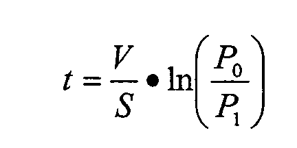
- t =
- Pumpzeit
- V =
- Volumen
- S =
- Saugvermögen
- P0 =
- Startdruck (Atmosphärendruck)
- P1 =
- Zieldruck (Übergabedruck, Umschleusdruck)
- t =
- pumping time
- V =
- volume
- S =
- Pumping speed
- P 0 =
- Starting pressure (atmospheric pressure)
- P 1 =
- Target pressure (transfer pressure, transfer pressure)
Da beiden Möglichkeiten technische und wirtschaftliche Grenzen gesetzt sind, ist man bei
Inline-Beschichtungsanlagen mit hoher Produktivität und entsprechend kurzer Zykluszeit
dazu übergegangen den Evakuier-/Belüftungsvorgang auf zwei oder mehr Schleusenkammern
aufzuteilen. Für z. B. die Einschleusseite bedeutet dies, dass in einer ersten Einschleuskammer
von Atmosphäre bis zu einem Zwischendruck z. B. 10 hPa evakuiert wird
und in einer zweiten Schleusenkammer dann vom Zwischendruck (bzw. Ausgleichsdruck)
bis zum Übergabedruck z.B. 5E-2 hPa. In solch einer 5-Kammeranlage (2 Eintrittsschleusen,
2 Austrittsschleusen, 1 Prozesskammer) wird das Ein- und Ausschleusen auf jeweils
zwei Kammern verteilt, erfolgt also in zwei Schritten und ist auf zwei Zyklen verteilt. Damit
war es zum Bsp. bei Architekturglasbeschichtungsanlagen mit Schleusenvolumen von ca. 2
m3 bis 5 m3 möglich, die Zykluszeit von ca. 60 s bis 90 s auf ca. 40 s bis 50 s zu senken. Um
zu noch kürzeren Zykluszeiten zu gelangen, z.B. t < 30 s, wurde das Prinzip des zweistufigen
Schleusens um eine weitere Stufe ergänzt und Anlagen mit je drei Ein-/ bzw. Ausschleuskammem
gebaut. Diese sogenannten 7-Kammeranlagen und auch die schnellen 5-Kammeranlagen
haben gegenüber den 3-Kammeranlagen die Eigenschaft, dass die reine
Pumpzeit (Evakuierzeit) nur ca. die halbe (z.B. 17 s von 35 s) oder bei noch schnelleren
Anlagen z.B. nur noch 25% der Zylduszeit (5 s von 20 s) einnimmt, während bei langsamen
und älteren Anlagen die Pumpzeit noch den größten Teil der Zykluszeit einnahm (z.B. 60 s
von 90 s). Stand der Technik ist es, jeder Schleusenkammer (Schleusenstufe) einen für den
jeweiligen Arbeitsbereich geeigneten Vakuumpumpstand zuzuordnen, d.h. z.B. der ersten
Einschleuskammer (1) einen atmosphärentauglichen Pumpstand für den Druckbereich 1000
hPa bis z.B. 10 hPa und der zweiten Einschleuskammer (2) einen mehrstufigen z.B. 3-stufigen
Rootspumpstand für den Druckbereich 10 hPa bis 2E-2 hPa.Since both possibilities have technical and economic limits, in in-line coating systems with high productivity and correspondingly short cycle time, the evacuation / aeration process has been split over two or more lock chambers. For z. B. the Einschleusseite this means that in a first Einschleuskammer from atmosphere to an intermediate pressure z. B. 10 hPa is evacuated and in a second lock chamber then from the intermediate pressure (or compensation pressure) to the transfer pressure, for example, 5E-2 hPa. In such a 5-chamber system (2 entrance locks, 2 exit locks, 1 process chamber) is the in and out distributed in two chambers, thus takes place in two steps and is distributed over two cycles. For example, it was possible to reduce the cycle time from approx. 60 s to 90 s to approx. 40 s to 50 s for architectural glass coating systems with a lock volume of approx. 2 m 3 to 5 m 3 . In order to achieve even shorter cycle times, eg t <30 s, the principle of the two-stage lock has been extended by a further stage and systems with three in / out and Ausschleuskammem built. These so-called 7-chamber plants and also the fast 5-chamber plants have the property compared to the 3-chamber plants that the pure pumping time (evacuation time) is only about half (eg 17 s of 35 s) or with even faster plants eg only 25 % of the cylinder time (5 s of 20 s), while in slow and older systems, the pumping time was still the largest part of the cycle time (eg 60 s of 90 s). The state of the art is to assign each lock chamber (lock stage) a vacuum pumping station which is suitable for the respective working area, ie the first in-pass chamber (1) an atmospheric pumping station for the pressure range 1000 hPa to
Aufgabe der vorliegenden Erfindung ist somit die Leistungsfähigkeit einer Schleusenanordnung für Vakuumbehandlungsanlagen insbesondere der bestehenden 5-Kammer- bzw. 7-Kammersysteme, also mit zwei bis drei Einschleus- und Ausschleuskammern sowie einer Prozesskammer zu verbessern und insbesondere kürzere Evakuierzeiten und somit kürzere Taktzeiten für die Schleusenanordnung zu realisieren. Durch die höhere Leistungsfähigkeit sollen auch die Kosten für die Pumpanordnungen der Schleusenkammern reduziert werden, bzw. Schleusenkammern eingespart werden, was wiederum einen Kosten- und Platzvorteil bieten soll. Weiterhin besteht ein Aspekt der vorliegenden Erfindung darin, niedrigere Übergabedrücke bei gegebenen Zyklus- und Pumpzeiten zu erreichen.The object of the present invention is thus the performance of a lock arrangement for vacuum treatment plants, in particular the existing 5-chamber or 7-chamber systems, So with two to three Einschleus- and Ausschleuskammern and a Process chamber to improve and in particular shorter evacuation and thus shorter To realize cycle times for the lock arrangement. Due to the higher efficiency should also be reduced the cost of the pumping arrangements of the lock chambers, Lock chambers are saved, which in turn a cost and space advantage should offer. Furthermore, one aspect of the present invention is lower transfer pressures to achieve at given cycle and pumping times.
Diese Aufgabe wird gelöst durch eine Schleusenanordnung mit den Merkmalen des Anspruchs
1 oder 14, sowie einem Verfahren zum Betrieb einer Schleusenanordnung mit den
Merkmalen des Anspruchs 25 oder 28. Vorteilhafte Ausgestaltungen sind Gegenstand der
abhängigen Ansprüche. This object is achieved by a lock arrangement with the features of the
Die vorliegende Erfindung beruht nach einem ersten Aspekt auf der Erkenntnis, dass die Leistungsfähigkeit der Pumpanordnungen und somit die Zeit für das Evakuieren von Schleusenkammern verbessert bzw. verkürzt werden kann, wenn die Pumpanordnungen variabel den entsprechenden Bedürfnissen an den einzelnen Einschleuskammern angepasst werden, insofern als ein möglichst hoher zeitlicher Einsatz der Pumpanordnungen angestrebt wird. Damit kann durch Ausnutzung bestehender Pumpressourcen eine Erhöhung der effektiven Pumpleistung bzw. eine frühere Übergabe des Substrats von einer Einschleuskammer zur anderen realisiert werden. Gemäß der Erfindung wird somit nicht mehr starr daran festgehalten, dass eine Pumpeinrichtung für eine bestimmte Einschleuskammer zur Verfügung steht, sondern die Grundidee der Erfindung besteht darin, dass verschiedene Pumpeinrichtungen während des Einschleusvorgangs in geeigneter Weise mit einander gruppiert oder verbunden bzw. umgruppiert werden, um eine optimale Absaugleistung zu erreichen bzw. ein möglichst frühzeitiges Übergeben von einer Schleusenkammer zur anderen bei noch hohen Übergabedrücken zu ermöglichen.The present invention is based on a first aspect of the finding that the Performance of the pumping arrangements and thus the time for the evacuation of Lock chambers can be improved or shortened when the pumping arrangements variably adapted to the corresponding needs at the individual sluice chambers be sought insofar as the highest possible temporal use of the pumping arrangements becomes. Thus, by exploiting existing pumping resources, an increase in the effective pump power or earlier transfer of the substrate from a Einschleuskammer to be realized to the other. According to the invention is thus no longer rigid noted that a pumping device for a particular Einschleuskammer to Is available, but the basic idea of the invention is that different Pumping devices during the Einschleusvorgangs in a suitable manner with each other grouped or connected or regrouped to provide optimal suction performance reach as early as possible from one lock chamber to another to allow for even high transfer pressures.
Entsprechend wird eine erste Pumpeinrichtung, die primär für eine erste Schleusenkammer vorgesehen ist, nicht nur für diese verwendet, sondern auch für eine zweite Schleusenkammer, wobei lediglich entsprechende Verbindungen von der Pumpeinrichtung zu der ersten Schleusenkammer und zur zweiten Schleusenkammer vorgesehen werden müssen. Auf diese Weise ist es möglich, je nach Bedarf und Stadium des Einschleusprozesses die Pumpleistung bzw. Saugvermögen der ersten Pumpeinrichtung entweder der ersten Einschleuskammer oder der zweiten Einschleuskammer oder beiden gleichzeitig zur Verfügung zu stellen.Accordingly, a first pumping device, which is primarily for a first lock chamber is provided, not only used for this, but also for a second lock chamber, only corresponding connections from the pumping device to the first Lock chamber and the second lock chamber must be provided. To this It is possible, depending on the needs and stage of the Einschleusprozesses the pump power or pumping speed of the first pumping device either the first Einschleuskammer or the second infeed chamber or both at the same time put.
Ferner wird diese erste Pumpeinrichtung nicht nur direkt und unmittelbar der zweiten Einschleuskammer zur Verfügung gestellt, sondern die erste Pumpeinrichtung wird gemäß einer bevorzugten Alternative zusätzlich bzw. alternativ als Vorpumpstufe für eine zweite Pumpeinrichtung dieser nachgeschaltet, die primär für das Abpumpen der zweiten Schleusenkammer vorgesehen ist.Furthermore, this first pumping device is not only directly and immediately the second Einschleuskammer provided, but the first pumping device is according to a preferred alternative additionally or alternatively as a pre-pumping stage for a second Pumping device downstream of this, the primary for the pumping of the second lock chamber is provided.
Somit kann die Einsatzmöglichkeit der ersten Pumpeinrichtung weiter erhöht und die Pumpleistung besser verteilt werden. Thus, the possible use of the first pumping device further increases and the Pumping power to be better distributed.
Nach einer weiteren bevorzugten Ausführungsform wird eine dritte Pumpeinrichtung vorgesehen, die als nachgeschaltete Pumpstufe für die zweite Pumpeinrichtung, insbesondere im Bereich der Schleusenkammer mit niedrigeren Drücken die zweite Pumpeinrichtung unterstützt und zwar insbesondere dann, wenn die erste Pumpeinrichtung als Vorpumpstufe nicht mehr zur Verfügung steht, da sie hauptsächlich für die erste Schleusenkammer Verwendung finden soll.According to a further preferred embodiment, a third pumping device is provided, as a downstream pumping stage for the second pumping device, in particular in Area of the lock chamber with lower pressures the second pumping device supports and in particular when the first pumping means not as a pre-pumping stage More is available as they are mainly used for the first lock chamber should find.
Alternativ hierzu kann nach einer weiteren Ausführungsform eine dritte Pumpeinrichtung als gemeinsame Vorpumpstufe für die erste Pumpeinrichtung und die zweite Pumpeinrichtung vorgesehen sein, wobei die dritte Pumpeinrichtung entweder als Vorpumpstufe für die erste Pumpeinrichtung oder die zweite Pumpeinrichtung oder für beide zusammen eingesetzt werden kann. Auch damit ist also gewährleistet, dass die dritte Pumpeinrichtung ähnlich wie die erste Pumpeinrichtung die Pumpleistung veränderbar, insbesondere mit dem Verlauf des Einschleusprozesses veränderbar den Einschleuskammern zur Verfügung stellen kann. Entsprechend wird entweder dadurch die gewonnene Pumpleistung zur Reduzierung der Evakuierzeit verwendet oder es werden niedrigere Übergabedrücke ermöglicht.Alternatively, according to another embodiment, a third pumping device as a common pre-pumping stage for the first pumping device and the second pumping device be provided, wherein the third pumping device either as a pre-pumping stage for the first pumping device or the second pumping device or used together for both can be. This also ensures that the third pumping device is similar as the first pumping device, the pump power variable, in particular with the Course of Einschleusprozesses changeable provide the Einschleuskammern can. Accordingly, either the recovered pump power is thereby reduced the evacuation time is used or it allows lower transfer pressures.
Gemäß einer weiteren vorteilhaften Ausgestaltung der vorliegenden Erfindung kann bei parallel nebeneinander geschalteten Pumpen einer Pumpeinrichtung ein entsprechender Bypass vorgesehen werden, so dass eine der parallel geschalteten Pumpen durch entsprechendes Freischalten des Bypasses und geeignetes Abtrennen der übrigen Verbindungsleitungen diese Pumpe zu den vorher parallel geschalteten Pumpen in Reihe nachgeschaltet wird, um einen mehrstufigen Pumpstand zu erzeugen. Dies hat den Vorteil, dass je nach erforderlicher Pumpleistung bzw. Druckverhältnissen durch einfache Umgruppierung der Pumpen die Pumpleistung dem Bedarf angepasst werden kann. Beispielsweise für den Fall, dass die erste Pumpeinrichtung als Vorpumpstufe für die zweite Pumpeinrichtung zur Verfügung steht, kann die entsprechende Pumpe parallel mit den anderen Pumpen in der zweiten Pumpeinrichtung betrieben werden, während bei einem Abschalten der ersten Pumpeinrichtung als Vorpumpstufe die Pumpe mit dem Bypass den anderen Pumpen der zweiten Pumpeneinrichtung nachgeschaltet wird, um mit diesen einen mehrstufigen Pumpstand zu bilden. According to a further advantageous embodiment of the present invention can at parallel side by side connected pumps a pumping device a corresponding bypass be provided so that one of the pumps connected in parallel by appropriate Disconnecting the bypass and suitable separation of the remaining connecting lines this pump is connected in series with the previously parallel connected pumps in series to create a multi-stage pumping station. This has the advantage that, depending on the required Pumping power or pressure ratios by simply regrouping the pumps Pump power can be adjusted to the needs. For example, in case the first pumping device as a pre-pumping stage for the second pumping device available the corresponding pump can be in parallel with the other pumps in the second Pumping device are operated while at a shutdown of the first pumping device as pre-pumping pump with the bypass the other pumps of the second Pump device is connected downstream, with this a multi-stage pumping station to form.
Gemäß einer weiteren vorteilhaften Gestaltung kann bei parallel nebeneinander geschalteten Pumpen insbesondere der zweiten Pumpeinrichtung für die zweite Schleusenkammer parallel zu diesen Pumpen eine differenzdruckgesteuerte Umwegklappe vorgesehen werden, so dass automatisch nach den vorherrschenden Druckverhältnissen die parallelen Pumpeinrichtungen, insbesondere die zweite Pumpeinrichtung auch bei hohen Ansaugdrücken betrieben werden können. Durch die Differenzdruckklappe K2 wird nämlich die Ausblasseite der parallel geschalteten Pumpen mit der Ansaugseite, beispielsweise über die zweite Schleusenkammer, verbunden bzw. kurzgeschlossen, um einen maximalen Differenzdruck einzurichten. Dadurch wir die maximale Kompression der parallel geschalteten Pumpen und damit auch ihre mechanische bzw. elektrische Leistungsaufnahme begrenzt, so dass diese Pumpen bereits bei viel höheren Ansaugdrücken verwendet werden können, als ohne Umwegklappe. Dadurch können derartige parallel geschaltete Pumpen, beispielsweise Rootspumpen, auch bei relativ hohen Drücken schon mitpumpen und ihr Saugvermögen in einer frühen Abpumpphase zur Verfügung stellen. Auf diese Weise kann auf aufwändige Pumpen für die zweite Pumpeinrichtung, wie beispielsweise voreinlassgekühlte Wälzkolbenpumpen (Rootspumpen), die einen hohen zulässigen Differenzdruck von beispielsweise > 800 hPa beherrschen können, verzichtet werden. Außerdem ist es damit möglich die zweite Pumpeinrichtung ständig an der zweiten Schleusenkammer angeschlossen zu lassen, ohne dass entsprechende Ventile in den Leitungen zu der Schleusenkammer geschlossen werden müssten. Auch dadurch ergibt sich eine bessere Auslastung der Pumpen der zweiten Pumpeinrichtung bzw. eine vereinfachte Gestaltung der Pumpanordnung. Statt einer einzigen parallel geschalteten Umwegklappe kann jeder Pumpe eine eigene Differenzdruckklappe zugeordnet werden oder es können Pumpen mit integrierten Umwegklappen (Differenzdruckventilen) eingesetzt werden.According to a further advantageous embodiment can be connected in parallel side by side Pumping in particular the second pumping device for the second lock chamber in parallel to these pumps a differential pressure controlled Umwegklappe be provided so that automatically after the prevailing pressure conditions the parallel pumping devices, in particular, the second pumping device operated even at high suction pressures can be. By the differential pressure flap K2 namely the Ausblasseite the pumps connected in parallel with the suction side, for example via the second Lock chamber, connected or short-circuited to a maximum differential pressure to set up. This gives us the maximum compression of the pumps in parallel and so that their mechanical or electrical power consumption is limited so that this Pumps can already be used at much higher suction pressures, as without detour flap. As a result, such parallel-connected pumps, for example Roots pumps, even at relatively high pressures already pump and their pumping speed in provide an early pumping phase. In this way can be elaborate Pumps for the second pumping device, such as pre-inlet-cooled Roots pumps (Roots pumps), which have a high allowable differential pressure of, for example > 800 hPa can be dispensed with. It is also possible with the second pumping device to be constantly connected to the second lock chamber, without corresponding valves in the lines closed to the lock chamber would have to be. This also results in a better utilization of the second pump Pumping device or a simplified design of the pumping arrangement. Instead of a single one Parallel bypass valve can each pump its own differential pressure flap or pumps with integrated bypass valves (differential pressure valves) be used.
Es ist selbstverständlich, dass die verschiedenen Pumpeinrichtungen ein oder mehrere parallel zueinander geschaltete ein- oder mehrstufige Vakuumpumpen umfassen können, wie z. B. ölabgedichtete oder trockenverdichtende Vakuumpumpen, insbesondere Drehschieberpumpen, Kreiskolbenpumpen, Sperrschieberpumpen, Wälzkolbenpumpen, Trockenläufer, insbesondere Schraubenpumpen, Rootspumpen, insbesondere voreinlassgekühlte Rootspumpen usw. It is understood that the various pumping means one or more parallel may comprise single or multi-stage vacuum pumps connected to one another, such as z. As oil-sealed or dry-compressing vacuum pumps, in particular rotary vane pumps, Rotary piston pumps, gate valves, Roots pumps, dry runner, in particular screw pumps, Roots pumps, in particular pre-inlet cooled Roots pumps etc.
Durch die variable Gestaltung der Pumpleistung ist es insbesondere auch möglich ganz auf ölabgedichtete Pumpeinrichtungen zu verzichten und nur trockenverdichtende Vakuumpumpen wie z. B. Schraubenpumpen zu verwenden.Due to the variable design of the pump power, it is also possible in particular completely oil-sealed pumping devices and only dry-compressing vacuum pumps such as B. to use screw pumps.
Nach einem zweiten Aspekt wird eine Beschleunigung des Schleusenvorgangs dadurch erreicht, dass Puffereinrichtungen vorgesehen werden, die ein Puffervolumen zur Verfügung stellen, welches beispielsweise in Zeiten, in denen das Saugvermögen bestimmter Pumpeinrichtungen für den unmittelbaren Evakuierprozess nicht benötigt wird, oder ein direktes Abpumpen noch nicht möglich ist, evakuiert wird. Auf diese Weise wird sozusagen das Saugvermögen bzw. die Pumpleistung in der Puffereinrichtung gespeichert und im richtigen Zeitpunkt durch einen schlagartigen Druckausgleich für die Evakuierung bzw. Druckabsenkung der Schleusenkammern zur Verfügung gestellt. Der schlagartige Druckausgleich ermöglicht eine sehr schnelle Evakuierung innerhalb von Bruchteilen von Sekunden, also nahezu in "Nullzeit".According to a second aspect, an acceleration of the lock operation is achieved by that buffer means are provided which provide a buffer volume which, for example, in times when the pumping speed of certain pumping devices is not needed for the immediate evacuation process, or a direct one Pumping off is not possible, is evacuated. In this way, so to speak Suction or the pump power stored in the buffer device and in the right Time by a sudden pressure equalization for the evacuation or pressure reduction the lock chambers provided. The sudden pressure equalization allows a very fast evacuation within fractions of seconds, so close in no time.
Vorzugsweise kann für jede Schleusenkammer eine eigene Puffereinrichtung mit einem entsprechenden Puffervolumen zur Verfügung gestellt werden, wobei zusätzlich zu diesen externen Puffereinrichtungen die Schleusenkammern selbst ebenfalls als Puffer dienen können, wenn nämlich die dem Vakuumbereich näherliegende Schleusenkammer vorevakuiert wird, um dann durch einen Druckausgleich mit einer vorgeschalteten Schleusenkammer für eine schlagartige Druckabsenkung zu sorgen.Preferably, for each lock chamber its own buffer means with a corresponding buffer volume are provided, in addition to these external buffer devices, the lock chambers themselves can also serve as a buffer, namely, if the vacuum chamber closer to the lock chamber pre-evacuated is then, by a pressure equalization with an upstream lock chamber for to provide a sudden pressure reduction.
Die externen Puffereinrichtungen können mit separaten Pumpeinrichtungen versehen sein, wobei es jedoch besonders zweckmäßig ist für die für die Schleusenkammern bereits vorhandenen Pumpeinrichtungen alleine oder zusätzlich zu separaten Pumpeinrichtungen der Puffereinrichtungen mit einzusetzen. Auf diese Weise kann eine optimale Ausnutzung der Pumpeinrichtungen der Schleusenanordnung gewährleistet werden.The external buffer means may be provided with separate pumping means, but it is particularly useful for those already existing for the lock chambers Pumping devices alone or in addition to separate pumping devices of Use buffer devices with. In this way, optimal utilization of the Pumping devices of the lock arrangement can be ensured.
Es ist für den Fachmann selbstverständlich, dass die beschriebenen Maßnahmen sowohl an der Einschleus- als auch an der Ausschleusseite verwirklicht werden können. It is natural for the expert that the measures described both to the Einschleus- and on the Ausschleusseite can be realized.
Weitere Vorteile, Kennzeichen und Merkmale der vorliegenden Erfindung werden bei der nachfolgenden, detaillierten Beschreibung bevorzugter Ausführungsformen anhand der beigefügten Zeichnungen deutlich. Die Zeichnungen zeigen dabei in rein schematischer Weise in
- Fig. 1
- eine schematische Darstellung des Einschleusbereichs einer Glasbeschichtungsanlage mit entsprechender Pumpanordnung;
- Fig. 2
- eine weitere Ausführungsform einer Schleusenanordnung in einem Einschleusbereich vergleichbar der Darstellung in Fig. 1,
- Fig. 3
- eine dritte Ausführungsform eines Einschleusbereichs mit einer zu Fig. 1 ähnlichen Darstellung; und in
- Fig. 4
- eine vierte Ausführungsform einer Schleusenanordnung.
- Fig. 1
- a schematic representation of the Einschleusbereichs a glass coating plant with appropriate pumping arrangement;
- Fig. 2
- a further embodiment of a lock arrangement in a Einschleusbereich comparable to the representation in Fig. 1,
- Fig. 3
- a third embodiment of a Einschleusbereichs with a similar to Figure 1 representation; and in
- Fig. 4
- A fourth embodiment of a lock arrangement.
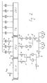
Fig. 1 zeigt in einer schematischen Darstellung den Einschleusbereich einer Vakuumbehandlungsanlage, hier Glasbeschichtungsanlage mit zwei Einschleuskammern EK1 und EK2, sowie eine Transferkammer TK und eine Sputterkammer SK1. An der Sputterkammer SK1 und der Transferkammer TK sind eine Vielzahl Hochvakuumpumpen angeordnet, um die Hochvakuumbedingungen für den Beschichtungsbereich einzustellen.1 shows a schematic representation of the Einschleusbereich a vacuum treatment plant, here glass coating plant with two inlet chambers EK1 and EK2, as well as a transfer chamber TK and a sputtering chamber SK1. At the sputtering chamber SK1 and the transfer chamber TK are a variety of high vacuum pumps arranged to to set the high vacuum conditions for the coating area.
Die Einschleuskammern EK1 und EK2 sind gegenüber der äußeren Umgebung durch die Ventilklappe VK1, sowie gegenüber der Transferkammer TK über die Ventiklappe VK3 abgetrennt. Untereinander wird die Trennung durch die Ventilklappe VK2 bewirkt.The Einschleakammern EK1 and EK2 are compared to the external environment through the Valve flap VK1, as well as with respect to the transfer chamber TK via the valve flap VK3 separated. Separation is effected by the valve flap VK2.
An der Einschleuskammer EK1 ist ein Ventil VFlut zum Belüften der Einschleuskammer EK1 angeordnet.At the inward EK1 a valve V flood is arranged for aerating the inward EK1.
An der Einschleuskammer EK1 ist ferner eine erste Pumpeinrichtung P1 mit fünf parallel
geschalteten Drehschieberpumpen vorgesehen, die über die Leitung 1 und das Ventil V1 mit
der Einschleuskammer EK1 verbunden ist. Die Pumpeinrichtung P1 ist darüber hinaus über
die Leitung 2 und das Ventil V2 mit der Einschleuskammer EK2 verbunden. Ferner ist die
Pumpeinrichtung P1 noch über die Leitung 3, welche durch das Ventil V5 abschließbar ist,
mit der zweiten Pumpeinrichtung P2, P3, die durch die parallel geschalteten Rootspumpen
P2 und P3 gebildet wird, verbunden.At the Einschleuskammer EK1 is also a first pumping device P1 with five parallel
switched rotary vane pumps provided via the
Die Rootspumpen P2 und P3 der zweiten Pumpeinrichtung sind untereinander über die
Leitung 5 an der Ausblasseite miteinander verbunden, wobei die Leitung 5 über das Ventil
V7 absperrbar ist. Im übrigen sind die Pumpen P2 und P3 über die Leitungen 4 und den
darin vorgesehenen Ventilen V3 und V4 mit der Einschleuskammer EK2 verbunden. Darüber
hinaus ist eine dritte Pumpeinrichtung P4 aus einem zweistufigen Rootspumpenstand
mit einer Rootspumpe und einer nachgeschalteten Drehschieberpumpe vorgesehen, die über
die Leitung 6, welche das Ventil V6 aufweist, mit der zweiten Pumpeinrichtung und hier
insbesondere mit der Leitung 5 verbunden ist.The Roots pumps P2 and P3 of the second pumping means are interconnected via the
Darüber hinaus sind an der Einschleuskammer EK2 Hochvakuumpumpen vorgesehen, die
parallel zueinander geschaltet sind und über die Ventile Vh1 bis Vh3 an die Einschleuskammer
2 zuschaltbar sind.In addition, high-vacuum pumps are provided at the Einschleuskammer EK2, the
are connected in parallel to each other and via the valves Vh1 to Vh3 to the
Das Einschleusen in eine derartige Schleusenanordnung erfolgt in der Weise, dass zunächst die Ventilklappe VK1 der ersten Einschleuskammer EK1 geöffnet wird und das Substrat in die Einschleuskammer EK1 transportiert wird. Danach wird die Ventilklappe VK1 geschlossen und das Ventil V1 zum Pumpstand P1 geöffnet, so dass die Einschleuskammer EK1 abgepumpt werden kann.The introduction into such a lock arrangement takes place in such a way that first the valve flap VK1 of the first Einschleuskammer EK1 is opened and the substrate in the Einschleuskammer EK1 is transported. Thereafter, the valve VK1 is closed and the valve V1 is opened to the pumping station P1, so that the Einschleuskammer EK1 can be pumped out.
Danach werden die Ventile V3, V4 und V5 geschlossen und das Ventil V2, sowie die Ventilklappe VK2 geöffnet. Dies geschieht beispielsweise bei einem Druck von 200 hPa. Gleichzeitig wird das Substrat nun von der ersten Einschleuskammer EK1 in die zweite Einschleuskammer EK2 transportiert.Thereafter, the valves V3, V4 and V5 are closed and the valve V2, and the valve flap VK2 opened. This happens, for example, at a pressure of 200 hPa. At the same time, the substrate is now from the first Einschleuskammer EK1 in the second Einschleuskammer EK2 transported.
Wenn ein geeigneter Druck erreicht ist, beispielsweise 80 hPa, werden die Ventile V5 und V3 geöffnet und die Ventile V1 und V2 geschlossen. Gleichzeitig oder mit geringer Verzögerung werden die Ventile V4 und V7 geöffnet. Nunmehr wird auch das Ventil V6 geöffnet, wobei jedoch dieses Ventil V6 optional vorhanden ist und nur bei einer bestimmten Art des Pumpstandes P4 vorhanden sein muss. Wird beispielsweise die dritten Pumpeinrichtung P4 aus einer Vorpumpe und einer Rootspumpe mit Umwegleitung gebildet, kann aus das optionale Ventil V6 verzichtet werden, da dann die dritte Pumpeinrichtung P4 bei Atmosphäre oder sehr hohen Ansaugdrücken, z. B. 100 hPa bis 300 hPa zugeschaltet bzw. durchgängig betrieben werden kann.When a suitable pressure is reached, for example 80 hPa, the valves V5 and V3 open and the valves V1 and V2 closed. At the same time or with a slight delay the valves V4 and V7 are opened. Now also the valve V6 is opened, however, this valve V6 is optionally present and only for a certain type of Pumping station P4 must be present. If, for example, the third pumping device P4 formed from a backing pump and a Roots pump with detour line, can be made from the optional V6 valve are omitted, since then the third pumping device P4 at atmosphere or very high suction pressures, eg. B. 100 hPa to 300 hPa switched on or continuously can be operated.
Anschließend werden die Ventile V1 und die Ventilklappe VK2 geschlossen, so dass die Einschleuskammer EK1 wieder belüftet und die Ventilklappe VK1 geöffnet werden kann, um das nächste Substrat in der Einschleuskammer EK1 aufzunehmen.Subsequently, the valves V1 and the valve flap VK2 are closed, so that the Einschleuskammer EK1 re-vented and the valve flap VK1 can be opened, to pick up the next substrate in the infeed chamber EK1.
Ferner wird nun das Ventil V5 geschlossen, so dass nicht mehr die erste Pumpeinrichtung P1 als Vorpumpstand für die zweite Pumpeinrichtung P2, P3 bzw. parallel zur dritten Pumpeinrichtung P4 arbeitet, sondern nur noch die dritte Pumpeinrichtung P4 als Haltepumpstand der zweiten Pumpeinrichtung P2, P3 nachgeschaltet ist, während die erste Pumpeinrichtung durch das Öffnen des Ventils V1 wieder zum Evakuieren der ersten Einschleuskammer EK1 eingesetzt wird.Furthermore, now the valve V5 is closed, so that no longer the first pumping device P1 as Vorpumpstand for the second pumping device P2, P3 or parallel to the third Pumping device P4 works, but only the third pumping device P4 as Haltepumpstand the second pumping device P2, P3 is connected downstream, while the first Pumping device by opening the valve V1 again to evacuate the first Einschleuskammer EK1 is used.
In der zweiten Einschleuskammer EK2 können nunmehr die optionalen Hochvakuumventile Vh1 bis Vh3 geöffnet werden, um die Einschleuskammer EK2 auf Hochvakuumbedingungen zu bringen. Bei einem Druck von ca. 0,3 hPa können die Ventile V3 und V4 geschlossen werden und nach Erreichen der entsprechenden Vakuumbedingungen z. B. bei einem Druck von 2 x 10 -3 hPa kann die Ventilklappe VK3 geöffnet werden, um das Substrat in den Prozessbereich (Transferkammer) überzuführen.In the second infeed chamber EK2, the optional high-vacuum valves Vh1 to Vh3 can now be opened in order to bring the infeed chamber EK2 to high-vacuum conditions. At a pressure of about 0.3 hPa valves V3 and V4 can be closed and after reaching the appropriate vacuum conditions z. B. at a pressure of 2 x 10 -3 hPa, the valve flap VK3 can be opened to transfer the substrate in the process area (transfer chamber).
Wichtig hierbei ist, dass die oben beschriebenen Vorgänge in bzw. an den beiden Einschleuskammern zum Teil gleichzeitig ablaufen, so dass eine möglichst geringe Zykluszeit erreicht wird. Dadurch, dass die ersten Pumpeinrichtung P1 nicht nur mit der Einschleuskammer EK1, sondern auch mit der zweiten Einschleuskammer EK2 verbunden ist, kann die erste Pumpeinrichtung P1 für einen längeren Zeitraum genutzt werden, um damit zu einer verkürzten Einschleuszeit beizutragen. It is important that the processes described above in or at the two Einschleuskammern run partly at the same time, so that the lowest possible cycle time is reached. Characterized in that the first pumping device P1 not only with the Einschleuskammer EK1, but also connected to the second Einschleuskammer EK2 can the first pumping device P1 can be used for a longer period of time to order To contribute to a shortened Einschleuszeit.
Vorteilhaft ist bei der beschriebenen Anordnung, bzw. dem beschriebenen Vorgehen, dass die Ventilklappe VK2 zwischen der Einschleuskammer EK1 und Einschleuskammer EK2 nicht erst bei dem Übernahmedruck der Rootspumpen P2 und P3 der zweiten Pumpeinrichtung, also bei ca. 15 hPa geöffnet werden kann, sondern schon bei höheren Drücken, im Bereich von 100 hPa bis 200 hPa insbesondere 150 hPa. Dadurch verringert sich die Pumpzeit in der Einschleuskammer EK1 um beispielsweise ein Drittel oder die Pumpeinrichtung P1 könnte hinsichtlich des Saugvermögens um ein Drittel verkleinert werden.It is advantageous in the described arrangement, or the procedure described that the valve flap VK2 between the Einschleuskammer EK1 and Einschleuskammer EK2 not only at the takeover pressure of the roots pumps P2 and P3 of the second pumping device, So at about 15 hPa can be opened, but even at higher pressures, in Range from 100 hPa to 200 hPa, in particular 150 hPa. This reduces the pumping time in the Einschleuskammer EK1 for example, a third or the pumping device P1 could be reduced by one third in terms of pumping speed.
Darüber hinaus ist vorteilhaft, dass die erste Pumpeinrichtung P1 über das Ventil V5 als Vorpumpstand der zweiten Pumpeinrichtung mit den Pumpen P2 und P3 eingesetzt werden kann, so dass die zweite Pumpeinrichtung mit den Pumpen P2 und P3 bei viel höheren Drücken eingesetzt werden kann. Hier ist schon ein Einsatz ab ca. 100 hPa statt bei 10 hPa möglich.Moreover, it is advantageous that the first pumping device P1 via the valve V5 as Pre-pumping the second pumping device with the pumps P2 and P3 are used can, so that the second pumping device with the pumps P2 and P3 at much higher pressures can be used. Here is already a use from about 100 hPa instead of 10 hPa possible.
Insbesondere können die Öffnungs- und Schließzeiten der verschiedenen Ventile, insbesondere das Öffnen von V5, V7, V3 und V4, sowie das Schließen von V2 so aufeinander abgestimmt werden, dass keine Unterbrechung des Saugvermögens entsteht und die Schaltzeiten die Zykluszeit nicht negativ beeinflussen.In particular, the opening and closing times of the various valves, in particular opening V5, V7, V3 and V4, as well as closing V2 so matched be made that no interruption of the pumping speed and the switching times do not negatively influence the cycle time.
Die dritte Pumpeinrichtung P4 hat die Aufgabe mit der zweiten Pumpeinrichtung P2, P3 einen mehrstufigen Pumpstand zu bilden, bis der notwendige Übergabedruck bzw. der Einschaltdruck für die optionalen Hochvakuumpumpen PH1 bis PH3 erreicht ist. Außerdem dient die dritte Pumpeinrichtung P4 dazu die zweite Pumpeinrichtung P2, P3 zu unterstützen, wenn die ersten Pumpeinrichtung P1 zum Evakuieren der Einschleuskammer EK1 benötigt wird und deshalb als Vorpumpstand für die zweite Pumpeinrichtung P2, P3 nicht mehr zur Verfügung steht.The third pumping device P4 has the task with the second pumping device P2, P3 to form a multi-stage pumping station until the necessary transfer pressure or the switch-on pressure for the optional high-vacuum pumps P H1 to P H3 is reached. In addition, the third pumping device P4 is used to support the second pumping device P2, P3, when the first pumping device P1 is required for evacuating the Einschleuskammer EK1 and therefore is no longer available as Vorpumpstand for the second pumping device P2, P3.
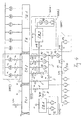
Bei der alternativen Ausführungsform der Fig. 3, die in weiten Teilen derjenigen der Fig. 1
entspricht und von daher im Folgenden nur bezüglich der Unterschiede beschrieben werden
soll, ist bei der zweiten Pumpeinrichtung zusätzlich zu den Rootspumpen P2 und P3 eine
dritte Rootspumpe P5 parallel geschaltet, die über eine weitere Leitung 14 und dem darin
angeordneten Ventil V 10 mit der Einschleuskammer EK2 verbunden ist. Darüber hinaus ist
parallel zur dritten Pumpe P5 eine Leitung 8 vorgesehen, die zwischen der Einschleuskammerleitung
14 und der die Ausblasseite der Pumpen P2, P3 und P5 verbindenden Leitung 5
angeordnet ist, wobei wiederum ein Ventil V11 in der Leitung 8 vorgesehen ist. Die Leitung
8 mündet zwischen dem Ventil V10 und der Pumpe P5 in die Leitung 14. Außerdem ist ein
Ventil V12 zwischen der Einmündung der Leitung 8 in die Leitung 5 und der Einmündung
der Leitung 6 in die Leitung 5 vorgesehen. Diese Bypassanordung zur Pumpe P5 ermöglichst
es, die Pumpe P5 durch Schließen des Ventils V10, sowie des Ventils V12 und Öffnen
des Ventils V11 den Rootspumpen P2 und P3 nachzuschalten, so dass die Pumpe P5 mit der
dritten Pumpeinrichtung P4, die hier durch eine einstufige Pumpanordnung aus einer Drehschieberpumpe
gebildet ist, einen mehrstufigen Rootspumpenstand bildet.In the alternative embodiment of Fig. 3, which in many parts of that of FIG
and therefore described below only in terms of differences
is, in the second pumping device in addition to the roots pumps P2 and P3 a
third Roots pump P5 connected in parallel, via another
Insofern ist es möglich zu dem Zeitpunkt, an dem die erste Pumpeinrichtung P1 nicht mehr als nachgeschaltete Pumpstufe für die zweite Pumpeinrichtung zur Verfügung steht, weil die erste Pumpeinrichtung P1 wieder die Einschleuskammer EK1 abpumpen muss, eine leistungsfähige mehrstufige Pumpanordnung für die Einschleuskammer EK2 durch Umgruppierung der Pumpe P5 bzw. Nachschaltung der Pumpe P5 zu den Pumpen P2 und P3 zu erreichen. Entsprechend werden bevor das Ventil V5 oder V7 geschlossen wird, die Ventile V10 und V12 geschlossen und das Ventil V11 geöffnet, um die Pumpe P5 den Pumpen P2 und P3 in Reihe nachzuschalten. Ansonsten entspricht der Ablauf demjenigen des Einschleusens in den Einschleusbereich der Fig. 1. Der Vorteil dieser Variante liegt jedoch darin, dass während des Abpumpens mit der zweiten Pumpeinrichtung P2, P3, P5 durch Schließen der Ventile V10 und V12 und Öffnen des Ventils V11 einen dreistufiger Rootspumpenstand mit der zweiten sowie dritten Pumpeinrichtung P4 als Vorpumpe bilden kann. Die dritte Stufe mit den Rootspumpen P2 und P3 kann durch Öffen/Schließen von V7 verdoppelt bzw. halbiert werden bzw. zwischen der ersten Pumpeinrichtung P1 und der dritten Pumpeinrichtung P4 aufgeteilt werden.In this respect, it is possible at the time at which the first pumping device P1 is no longer as a downstream pumping stage for the second pumping device is available, because the first pumping device P1 must again pump down the Einschleuskammer EK1, a powerful Multi-stage pumping arrangement for the infeed chamber EK2 by regrouping Pump P5 or downstream of the pump P5 to reach the pumps P2 and P3. Accordingly, before the valve V5 or V7 is closed, the valves V10 and V12 are closed and valve V11 is opened to pump P5 to pumps P2 and P3 in series. Otherwise, the procedure is the same as that of the infiltration in the Einschleusbereich of Fig. 1. The advantage of this variant, however, is that during Abpumpens with the second pumping device P2, P3, P5 by closing the Valves V10 and V12 and opening the valve V11 a three-stage root pump stand with can form the second and third pumping device P4 as a backing pump. The third stage with the roots pumps P2 and P3 can be doubled or halved by opening / closing V7 or between the first pumping device P1 and the third pumping device P4 be split.
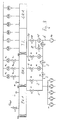
Bei der Ausführungsform der Fig. 2 ist die erste Pumpeinrichtung durch zwei parallel geschaltete,
einstufig ausgebildete voreinlassgekühlte Rootspumpen gebildet, die über die
Leitung 1 und das Ventil V1 mit der Einschleuskammer EK1 und über die Leitung 2 und
das Ventil V2 mit der Einschleuskammer EK2 verbunden sind. (Die Voreinlassgaskühlung
ist nicht dargestellt) In the embodiment of FIG. 2, the first pump device is connected by two parallel,
single-stage, pre-inlet cooled roots pumps are formed over the
Die zweite Pumpeinrichtung besteht aus den zweistufigen parallelen Rootspumpen P2 und
P3, die wiederum über die Leitungen 4 und entsprechende Ventile V3 und V4 mit der Einschleusklammer
EK2 verbunden sind.The second pumping means consists of the two-stage parallel Roots pumps P2 and
P3, in turn, via the
An der Ausblasseite der ersten Pumpeinrichtung P1 und der zweiten Pumpeinrichtung P2,
P3 ist eine dritte Pumpeinrichtung P4a, P4b aus parallel geschalteten einstufigen Trockenläufem
z. B. in Form von Schraubenpumpen vorgesehen, welche über die Leitung 6 mit der
zweiten Pumpeinrichtung P2, P3 bzw. deren gemeinsamen Leitung 5 verbunden sind, bzw.
über die Leitung 7 mit der ersten Pumpeinrichtung P1. In der Leitung 6 befindet sich das
Ventil V6 und in der Leitung 7 das Ventil V8, so dass die entsprechenden Verbindungen
abgetrennt werden können. Zusätzlich befindet sich in der Verbindungsleitung zwischen den
parallel geschalteten Schraubenpumpen P4a und P4b ein Ventil V9. Mit der Ausführungsform
der Fig. 2 kann sowohl die Einschleuskammer EK1 als auch die Einschleuskammer
EK2 über mehrstufige Pumpenstände abgepumpt werden, wobei insbesondere durch diese
Anordnung auf ölgedichtete Vorpumpen verzichtet werden kann, sondern alternativ in besonders
vorteilhafter Weise ausschließlich trockenverdichtende Pumpen eingesetzt werden
können.At the outlet side of the first pumping device P1 and the second pumping device P2,
P3 is a third pumping device P4a, P4b from parallel-connected single-stage dry rotors
z. B. provided in the form of screw pumps, which via the
Das Einschleusen eines Substrats in die Vakuumbehandlungsanlage der Fig. 2 erfolgt in der Weise, dass zunächst die Ventilklappe VK1 der ersten Einschleuskammer EK1 geöffnet wird und das Substrat in die Einschleusammer EK1 transportiert wird. Danach wird die Ventilklappe VK1 geschlossen und das Ventil V1 zur ersten Pumpeinrichtung P1 geöffnet, das bei hohem Drücken geförderte Gas, z. B. bei 500 bis 1000 hPa wird abhängig vom Vorpumpstand der dritten Pumpeinrichtung P4 über die Ausblasklappe K1 an die Atmosphäre ausgeblasen. Ab einem Übernahmedruck Pü von beispielsweise 300 hPa wird das Ventil V8 bzw. V8 und V9 geöffnet, so dass eine mehrstufige Pumpanordnung zum Abpumpen der Einschleuskammer EK1 gebildet wird.The introduction of a substrate into the vacuum treatment plant of FIG. 2 takes place in the Way, that initially the valve flap VK1 the first Einschleuskammer EK1 opened is and the substrate is transported into the Einschleusammer EK1. After that, the Valve flap VK1 closed and the valve V1 to the first pumping device P1 opened, the promoted at high pressure gas, z. B. at 500 to 1000 hPa depends on the Vorpumpstand the third pumping device P4 via the exhaust flap K1 to the atmosphere blown out. From a takeover pressure Pü of, for example, 300 hPa, the valve V8 or V8 and V9 open, so that a multi-stage pumping arrangement for pumping the Einschleuskammer EK1 is formed.
Nunmehr werden die Ventile V3 und V4 geschlossen, während das Ventil V2 und die Ventilklappe VK2 zwischen der Einschleuskammer EK1 und der Einschleuskammer EK2 geöffnet werden. Das Substrat wird nun von der ersten Einschleuskammer EK1 in die zweite Einschleuskammer EK2 transportiert.Now, the valves V3 and V4 are closed, while the valve V2 and the valve flap VK2 between the Einschleuskammer EK1 and the Einschleuskammer EK2 opened become. The substrate is now from the first Einschleuskammer EK1 in the second Transporting chamber EK2 transported.
Danach werden die Ventile V6, V3 und V4 geöffnet und ggf. die Ventile V8 und V9 geschlossen.
Dann wird die Ventilklappe VK2 und das Ventil V1 wieder geschlossen, so dass
die Eintrittskammer bzw. Einschleuskammer EK1 belüftet und die Ventilklappe VK1 geöffnet
werden kann, um das nächste Substrat in die Einschleuskammer EK1 einzubringen. Danach
werden die Ventile V8 und V2 geschlossen und V1 zum Evakuieren der ersten Einschleuskammer
EK1 geöffnet. Die Hochvakuumpumpen PH1 bis PH3 können entsprechend
dem Betrieb des ersten Ausführungsbeispiels gemäß der Fig. 1 über die Ventile Vh1 bis
Vh3 mit der Einschleuskammer EK2 verbunden werden, so dass dann die Ventile V3 und
V4 geschlossen werden können. Wenn die Einschleuskammer EK2 den Vakuumbedingungen
der Sputterkammer 1 entspricht, wird die Ventilklappe VK3 geöffnet und das Substrat
wird in den Prozessbereich eingeschleust. Auch hier laufen selbstverständlich die Vorgänge
in den beiden Schleusenkammern EK1 und EK2 zum Teil zeitgleich ab.Thereafter, the valves V6, V3 and V4 are opened and possibly the valves V8 and V9 closed. Then the valve flap VK2 and the valve V1 is closed again, so that the inlet chamber or inlet chamber EK1 can be ventilated and the valve flap VK1 can be opened in order to introduce the next substrate into the inlet chamber EK1. Thereafter, the valves V8 and V2 are closed and V1 opened to evacuate the first Einschleuskammer EK1. The high vacuum pumps P H1 to P H3 can be connected in accordance with the operation of the first embodiment shown in FIG. 1 via the valves Vh1 to Vh3 with the Einschleuskammer EK2, so that then the valves V3 and V4 can be closed. When the Einschleuskammer EK2 corresponds to the vacuum conditions of the sputtering
Der Vorteil dieser Anordnung besteht darin, dass die erste Pumpeinrichtung P1 und zudem auch die dritte Pumpeinrichtung P4 nahezu zu 100 % genutzt werden können, also nahezu über den gesamten Einschleuszyklus. Außerdem kann auch hier das Kammerventil VK2 bereits bei höheren Drücken, beispielsweise bei 100 bis 400 hPa, insbesondere 250 hPa geöffnet werden, was gegenüber einer Öffnung bei ca. 15 hPa, welcher dem Übernahmedruck der Rootspumpen P2 und P3 entspricht, eine deutlich verkürzte Pumpzeit für das Abpumpen der Einschleuskammer EK1 entspricht bzw. eine verkleinerte Ausbildung des entsprechenden Pumpstands ermöglicht.The advantage of this arrangement is that the first pumping device P1 and also The third pumping device P4 can be used almost 100%, so almost over the entire Einschleuszyklus. In addition, here can the chamber valve VK2 already opened at higher pressures, for example at 100 to 400 hPa, in particular 250 hPa which is opposite to an opening at about 15 hPa, which is the takeover pressure the root pumps P2 and P3 corresponds, a significantly shorter pumping time for pumping the Einschleuskammer EK1 corresponds or a reduced training of the corresponding Pumping possible.
Durch die variable Einsetzbarkeit einer dritten Pumpeinrichtung P4 als Vorpumpstand sowohl der ersten Pumpeinrichtung P1 als auch der zweiten Pumpeinrichtung P2, P3, wird zudem sowohl für die Einschleuskammer EK1 als auch für die Einschleuskammer EK2 ein variabel zu nutzender mehrstufiger Pumpstand bereitgestellt. Insbesondere kann bei allen gezeigten Ausführungsformen die Pumpleistung bzw. das Saugvermögen sozusagen mit dem Substrat auf der Einschleusseite oder allgemein mit der Evakuierungsrichtung von Atmosphäre zum Vakuum bzw. dem örtlichen Bedürfnis an Pumpleistung mitwandern, so dass von daher eine erhebliche Leistungssteigerung und Zeitverminderung einhergeht.Due to the variable applicability of a third pumping device P4 as Vorpumpstand both the first pumping device P1 and the second pumping device P2, P3, is In addition, both for the Einschleuskammer EK1 and for the Einschleuskammer EK2 provided variable to use multistage pumping station. In particular, at all shown embodiments, the pump power and the suction, so to speak with the substrate on the inlet side or in general with the evacuation direction of the atmosphere migrate to the vacuum or the local need for pump power, so that Therefore, a significant increase in performance and time reduction is accompanied.
Die Fig. 4 zeigt eine weitere Ausführungsform einer erfmdungsgemäßen Schleusenanordnung, die in großen Teilen mit derjenigen der Fig. 3 übereinstimmt.4 shows a further embodiment of a lock arrangement according to the invention, which largely coincides with that of FIG. 3.
Ein erster Unterschied besteht darin, dass die zweite Pumpeinrichtung mit den parallel geschalteten
Pumpen P2, P3 und P5 keinen Bypass 8 parallel zur Pumpe P5 wie in Fig. 3 aufweist,
sondern dass parallel zu den Leitungen 4, mit denen die Pumpen P2, P3 und P5 an der
zweiten Einschleuskammer EK2 angeschlossen sind, eine druckdifferenzgesteuerte Umwegklappe
K2 vorgesehen ist, die über die Leitung 9 und das Ventil V17 mit der zweiten
Einschleuskammer EK2 verbunden ist. Mittels dieser Anordnung ist es möglich, die parallel
geschalteten Rootspumpen P2, P3 und P5 bei relativ hohem Ansaugdruck zuzuschalten, um
entsprechend dem eingestellten Differenzdruck auch schon bei hohen Ansaugdrücken einen
Teil ihres Saugvermögens zum raschen Evakuieren zu nutzen. Die Umwegklappe K2 sorgt
nämlich durch eine Verbindung der Ausblasseite der Pumpen P2, P3 und P5 mit der Ansaugseite
über die zweite Einschleuskammer EK2 dafür, dass die Pumpen P2, P3 und P5
lediglich einen an der Umwegklappe K2 einstellbaren Differenzdruck bewältigen müssen.
Hierzu kann beispielsweise die Umwegklappe aus einem federbelasteten oder gewichtsbelasteten
Ventil bestehen, das sich bei einem festgelegten Überdruck auf der Ausblasseite der
Rootspumpen P2, P3 und P5 in Kammerrichtung öffnet. Auf diese Weise können die Ventile
V3, V4 und V 10 bei höheren Ansaugdrücken geöffnet werden bzw. offen stehen bleiben
und/oder es kann auf die Verwendung von voreinlassgekühlten Wälzkolbenpumpen, die
ebenfalls bei höheren Drücken Verwendung finden könnten, verzichtet werden, so dass der
Aufwand für die zweite Pumpeinrichtung bei gleichzeitiger Bereitstellung von höherem
Saugvermögen reduziert werden kann. Selbstverständlich können statt der einen differenzdruckgesteuerten
Umwegklappe K2 mehrere Differenzdruckklappen, beispielsweise für jede
Pumpe P2, P3 oder P5 vorgesehen werden oder Rootspumpen mit integrierter Umwegklappe
eingesetzt werden.A first difference is that the second pump means connected in parallel
Pumps P2, P3 and P5 has no
Die Anordnung der Umwegklappe K2 hat weiterhin den Vorteil, dass die Ventile V17, V3, V4 und V10 im Betrieb ständig geöffnet bleiben können, also nicht zwangsläufig in jedem Zyklus geschlossen werden müssen, insbesondere wenn auf die Hochvakuumpumpen PH1 bis PH3 verzichtet wird. Auf diese Weise wird der Betrieb ebenfalls vereinfacht.The arrangement of the Umwegklappe K2 also has the advantage that the valves V17, V3, V4 and V10 can remain open during operation, so do not necessarily have to be closed in each cycle, especially when the high vacuum pumps P H1 to P H3 is omitted. In this way, the operation is also simplified.
Ein zweiter Unterschied der Ausführungsform der Fig. 4 gegenüber derjenigen der Fig. 3 ist
dadurch gegeben, dass die parallel geschalteten Vakuumpumpen der ersten Pumpeneinrichtung
P1 über eine Leitung 10 und den darin vorgesehenen Ventilen V13 und V15 als
nachgeschaltete Stufe zur dritten Pumpeinrichtung P4 oder parallel zu weiteren Pumpen P9
über Ventil V16 und P10 über V13 zugeschaltet werden kann. Auf diese Weise ist es möglich,
durch Schließen des Ventils V5 und Öffnen der Ventile V6, V13, V15 und eventuell
V9 während des Abpumpens einen mehrstufigen Pumpstand mit der ersten Pumpeinrichtung
P1, der vierten Pumpeinrichtung P4 und der zweiten Pumpeinrichtung P2, P3 und P5
zu bilden. So kann aus dem zweistufigen Pumpstand ohne Unterbrechung des Saugvermögens
ein nahtloser Übergang zu einem dreistufigen Pumpstand erfolgen oder allgemein aus
einem n-stufigen Pumpstand ein n+1-stufiger Pumpstand gebildet werden. Es ist klar, dass
somit die Pumpe P9 mit dem Ventil V16 lediglich optional vorgesehen sein kann.A second difference of the embodiment of FIG. 4 from that of FIG. 3 is
Given that the parallel-connected vacuum pumps of the first pump device
P1 via a
Ein weiterer wesentlicher Unterschied der Ausführungsform der Fig. 4 gegenüber den vorangegangen
Ausführungsformen besteht darin, dass sie zusätzlich eine externe Puffereinrichtung
EB1 aufweist, die über das Ventil V 14 und die Leitung 8 sowie die Leitung 1 mit
der ersten Schleusenkammer EK1 verbunden ist. Die Puffereinrichtung EB1 stellt ein Puffervolumen
bereit, welches über die optional vorgesehene fünfte Pumpeinrichtung P6 oder
über die erste Pumpeinrichtung P1 abgesaugt werden kann. Mit dem so vorhandenen evakuierten
Puffervolumen kann der Druck in der ersten Schleusenkammer EK1 nach Öffnen
der Ventile V1 und V14 schlagartig abgesenkt werden. Auf diese Weise ist es möglich
Pumpleistung bzw. Saugvermögen in Zeiten zu nutzen, in denen die Pumpleistung bzw. das
Saugvermögen für die direkte Evakuierung der Einschleuskammern EK1 und EK2 nicht
benötigt wird oder das zusätzliche Versehen der fünften Pumpeinrichtung P6 an der Schleusenkammer
EK1 auf Grund der Druckverhältnisse nicht vorteilhaft ist. Diese Pumpleistung
bzw. das Saugvermögen wird sozusagen in der Puffereinrichtung EB1 gespeichert und dann
bei Bedarf der ersten Schleusenkammer EK1 zur Verfügung gestellt. Another essential difference of the embodiment of Fig. 4 with respect to the preceding
Embodiments consist in that they additionally an external buffer device
EB1, via the
In gleicher Weise kann auch die zweite Schleusenkammer EK2 als interne Puffereinrichtung wirken, wenn nämlich durch Öffnen der Ventile V1 und V2 ein Druckausgleich zwischen den Einschleuskammern EK1 und EK2 vorgenommen wird, so dass auch hier schlagartig der Druck abfällt. Insbesondere bei einer aufeinander abgestimmten Kombination eines Druckausgleichs zwischen erster Schleusenkammer EK1 und Puffereinrichtung EB1 und nachfolgendem Druckausgleich zwischen erster Schleusenkammer EK1 und zweiter Schleusenkammer EK2 können zwei Stufen einer raschen Druckabsenkung erzielt werden, wobei auch hier das Saugvermögen bezüglich der zweiten Schleusenkammer EK2 während eines größeren Zeitraumes des Schleusenprozesses Verwendung finden kann.In the same way, the second lock chamber EK2 as an internal buffer device act, if namely by opening the valves V1 and V2, a pressure equalization between the infiltration chambers EK1 and EK2 is made, so that abruptly the pressure drops. In particular, in a coordinated combination of a Pressure equalization between first lock chamber EK1 and buffer device EB1 and subsequent pressure equalization between first lock chamber EK1 and second Lock chamber EK2 can be achieved two stages of rapid pressure reduction, wherein also here the suction capacity with respect to the second lock chamber EK2 during a longer period of the lock process can be used.
Zusätzlich kann optional eine zweite externe Puffereinrichtung EB2 mit entsprechend optional
vorgesehener zusätzlicher sechster Pumpeinrichtung P7 vorgesehen werden, mittels der
ein Druckausgleich zwischen der zweiten Einschleuskammer 2 und der zweiten Puffereinrichtung
EB2 ebenfalls für eine schlagartige Druckabsenkung sorgt. Anstelle der sechsten
Pumpeinrichtung P7 kann das Puffervolumen der zweiten Puffereinrichtung EB2 auch
durch die zweite (P2, P3, P5), dritte (P4) und/oder weitere für die zweite Schleusenkammer
EK2 bereits vorgesehene Pumpeinrichtungen, wie beispielsweise P9 evakuiert werden.In addition, optionally a second external buffer device EB2 with corresponding optional
provided additional sixth pumping device P7 are provided by means of
a pressure equalization between the
In der Ausführungsform der Fig. 4 ist auch angedeutet, dass die Hochvakuumpumpen PH1 bis PH3 in allen Ausführungsformen weggelassen werden können, und von daher also nur optional sind, wenn über das Saugvermögen für die zweite Schleusenkammer EK2 ein ausreichendes Vakuum erzielt werden kann.In the embodiment of Fig. 4 is also indicated that the high vacuum pumps P H1 to P H3 can be omitted in all embodiments, and therefore therefore only optional, if on the pumping speed for the second lock chamber EK2 a sufficient vacuum can be achieved.
Die Ventile V3, V4, V10 und V17 dienen dazu, die zweite Schleusenkammer EK2 vom Pumpstand trennen zu können und erlauben eine unabhängige Belüftung der Kammer bzw. des Pumpstands. Sofern dies nicht als erforderlich angesehen wird, können diese Ventile auch entfallen. Die Ventile V3, V4, V10 und V17 sind jedoch auf jeden Fall notwendig, wenn die zweite Puffereinrichtung EB2 über die zweite Pumpeinrichtung P2, P3, P5 evakuiert werden soll, da dann eine Abtrennung von der zweiten Schleusenkammer EK2 notwendig ist. Sollte jedoch die zweite Puffereinrichtung EB2 nur durch die sechste Pumpeinrichtung P7 evakuiert werden, könnte die zweite Puffereinrichtung EB2 auch direkt mittels V 18 mit der zweiten Schleusenkammer EK2 verbunden sein. The valves V3, V4, V10 and V17 serve the second lock chamber EK2 from Separate pumping station and allow independent ventilation of the chamber or the pumping station. Unless this is considered necessary, these valves can also omitted. However, the valves V3, V4, V10 and V17 are definitely necessary when the second buffer device EB2 is evacuated via the second pumping device P2, P3, P5 should be, since then a separation of the second lock chamber EK2 necessary is. However, should the second buffer device EB2 only by the sixth pumping device P7 be evacuated, the second buffer device EB2 could also directly by means V 18 be connected to the second lock chamber EK2.
Der Schleusenvorgang läuft bei der Ausfamngsform gemäß der Fig. 4 in der folgenden Weise ab. Zunächst wird die Ventilklappe VK1 der ersten Schleusenkammer EK1 geöffnet und das Substrat wird in die erste Schleusenkammer EK1 transportiert. Dann wird die Ventilklappe VK1 geschlossen und das Ventil V1 zum Pumpenstand P1 geöffnet. Ventil V14 ist hierbei offen und die Ventile V2, V5 sowie V13 oder V15 sind geschlossen. Durch den Druckausgleich mit dem evakuierten Puffervolumen der ersten Puffereinrichtung EB1 wird der Druck in der ersten Schleusenkammer EK1 schlagartig von der Atmosphäre auf ca. 400 hPa gesenkt. Nunmehr wird V14 geschlossen und V2 geöffnet, so dass sich ein zweiter Druckausgleich anschließt, und zwar zwischen der ersten Schleusenkammer EK1 und der evakuierten zweiten Schleusenkammer EK2. Bei ungefähr gleichgroßen Kammervolumina von erster und zweiter Schleusenkammer EK1 und EK2 wird der Druck in beiden Kammern schlagartig auf ca. 200 hPa gebracht. Nunmehr wird die Ventilklappe VK2 geöffnet und das Substrat von der ersten Schleusenkammer EK1 in die zweite Schleusenkammer EK2 transportiert. Währenddessen wird das Ventil V5 geöffnet und die Ventile V1 und V2 werden geschlossen.The lock operation in the Ausfamngsform according to the Fig. 4 in the following Way off. First, the valve flap VK1 of the first lock chamber EK1 is opened and the substrate is transported into the first lock chamber EK1. Then the valve flap VK1 closed and the valve V1 to the pump stand P1 opened. Valve V14 is open and valves V2, V5 and V13 or V15 are closed. By the Pressure equalization with the evacuated buffer volume of the first buffer device EB1 is the pressure in the first lock chamber EK1 abruptly from the atmosphere to about 400 lowered hPa. Now V14 is closed and V2 opened, leaving a second Pressure equalization connects, between the first lock chamber EK1 and the evacuated second lock chamber EK2. At approximately equal chamber volumes of first and second lock chamber EK1 and EK2, the pressure in both chambers abruptly brought to about 200 hPa. Now, the valve flap VK2 is opened and the Substrate transported from the first lock chamber EK1 in the second lock chamber EK2. Meanwhile, valve V5 is opened and valves V1 and V2 become closed.
Gleichzeitig oder mit geringer Verzögerung werden die Ventile V6 und V15 und gegebenenfalls V13 geöffnet und das Ventil V5 geschlossen, so dass kein Bypass mehr zur dritten Pumpeinrichtung P4 besteht und nunmehr ein mehrstufiger Pumpbestand mit den Pumpstufen aus erster Pumpeinrichtung P1, zweiter Pumpeinrichtung P2, P3, P5 und dritter Pumpeinrichtung P4 besteht. Nunmehr wird die Ventilklappe VK2 geschlossen und die erste Schleusenkammer EK1 über das Ventil VFlut belüftet. Danach kann die Ventilklappe VK1 geöffnet und das nächste Substrat in die erste Schleusenkammer EK1 transportiert werden. Die optional vorhandenen Hochvakuumpumpen PH1 bis PH3 können nun durch das Öffnen der Ventile VH1 bis VH3 mit der zweiten Schleusenkammer EK2 in Verbindung gebracht werden. In diesem Fall werden die Ventile V3, V4, V10 und V17 geschlossen. Sind keine Hochvakuumpumpen an der zweiten Schleusenkammer EK2 vorgesehen, können diese Ventile im Betrieb ggf. durchgehend offen bleiben. Nunmehr kann die Ventilkappe VK3 geöffnet werden und das Substrat in den Prozessbereich bzw. die Transferkammer TK überführt werden. Die Ventile V 13 und V 15 werden geschlossen und das Ventil V14 wird geöffnet, so dass die erste Pumpeinrichtung das Puffervolumen der ersten Puffereinrichtung EB1 evakuieren kann. Falls die fünfte Pumpeinrichtung P6 vorhanden ist, kann das Puffervolumen der ersten Puffereinrichtung EB1 zusammen durch die erste Pumpeinrichtung P1 und die fünfte Pumpeinrichtung P6 evakuiert werden. Dann beginnt der Einschleusprozess von neuem.At the same time or with a slight delay, the valves V6 and V15 and optionally V13 are opened and the valve V5 is closed, so that there is no longer a bypass to the third pumping device P4 and now a multi-stage pumping stock with the pumping stages of the first pumping device P1, second pumping device P2, P3, P5 and third pumping device P4 exists. Now, the valve flap VK2 is closed and the first lock chamber EK1 vented via the valve V flood . Thereafter, the valve flap VK1 can be opened and the next substrate can be transported into the first lock chamber EK1. The optionally present high-vacuum pumps P H1 to P H3 can now be brought into contact with the second lock chamber EK2 by opening the valves VH1 to VH3. In this case, the valves V3, V4, V10 and V17 are closed. If no high-vacuum pumps are provided at the second lock chamber EK2, these valves may possibly remain open during operation, if necessary. Now, the valve cap VK3 can be opened and the substrate can be transferred into the process area or the transfer chamber TK. The valves V 13 and V 15 are closed and the valve V14 is opened, so that the first pumping means can evacuate the buffer volume of the first buffer device EB1. If the fifth pumping means P6 is present, the buffer volume of the first buffering means EB1 may be evacuated together by the first pumping means P1 and the fifth pumping means P6. Then the smuggling process starts again.
Wird bei der Schleusenanordnung der Fig. 4 die zweite externe Puffereinrichtung EB2 vorgesehen, so wird das Ventil V18 zum Druckausgleich zwischen zweiter Schleusenkammer EK2 und dem vorevakuierten Puffervolumen der zweiten Puffereinrichtung EB2 geöffnet, nachdem das Substrat die zweite Schleusenkammer EK2 erreicht hat und die Ventilklappe VK2 geschlossen wurde. Dadurch kann der Druck in der zweiten Schleusenkammer EK2 schlagartig von ca. 30 hPa auf 10 hPa abgesenkt werden.If the second external buffer device EB2 is provided in the lock arrangement of FIG. 4, so the valve V18 is for pressure equalization between the second lock chamber EK2 and the pre-evacuated buffer volume of the second buffer device EB2, after the substrate has reached the second lock chamber EK2 and the valve flap VK2 was closed. As a result, the pressure in the second lock chamber EK2 abruptly lowered from about 30 hPa to 10 hPa.
Während des Transports des Substrats von der zweiten Schleusenkammer EK2 in die Transferkammer
TK werden die Ventile V3, V4, V 10 und V17 geschlossen, um die zweite
Pumpeinrichtung mit den Pumpen P2, P3 und P5 zum Evakuieren des Puffervolumens der
zweiten Puffereinrichtung EB2 zu nutzen.During transport of the substrate from the second lock chamber EK2 into the transfer chamber
TK valves V3, V4,
Mit der vorgeschlagenen Lösung gemäß der Ausführungsform der Fig. 4 ist es aufgrund der Pufferlösungen möglich, in sehr kurzen Zeiten, d. h. Zeiten sehr viel kleiner als eine Sekunde, die Druckabsenkung über einen zweistufigen Druckausgleich in der ersten Schleusenkammer zu bewirken, um dann sofort das Substrat in die zweite Schleusenkammer überführen zu können. Mit einer zweiten Puffereinrichtung kann diese Wirkung auch für die zweite Schleusenkammer EK2 genutzt werden.With the proposed solution according to the embodiment of Fig. 4, it is due to the Buffer solutions possible, in very short times, d. H. Times much less than a second, the pressure reduction via a two-stage pressure equalization in the first lock chamber then immediately transfer the substrate into the second lock chamber to be able to. With a second buffer device, this effect for the second Lock chamber EK2 be used.
Die hier vorgestellten Vorgänge im Einschleusbereich können entsprechend analog auch für den Ausschleusbereich eingesetzt werden, ohne dass es hierfür einer näheren Beschreibung bedürfte, da der Fachmann die entsprechende Adaption in einfacher Weise vornehmen kann.The processes presented here in the Einschleusbereich can analogously also for the Ausschleusbereich be used without it for a closer description would require, since the expert can make the appropriate adaptation in a simple manner.
Claims (31)
Priority Applications (10)
| Application Number | Priority Date | Filing Date | Title |
|---|---|---|---|
| EP04007820.6A EP1582607B2 (en) | 2004-03-31 | 2004-03-31 | Loadlock arrangement for a vacuum treatment apparatus and method of operating it |
| DE502004008341T DE502004008341D1 (en) | 2004-03-31 | 2004-03-31 | Lock arrangement for a vacuum treatment plant and method for operating this |
| ES04007820T ES2316892T3 (en) | 2004-03-31 | 2004-03-31 | CLOSURE PROVISION FOR A VACUUM TREATMENT INSTALLATION AND PROCEDURE FOR OPERATION. |
| AT04007820T ATE412789T1 (en) | 2004-03-31 | 2004-03-31 | LOCK ARRANGEMENT FOR A VACUUM TREATMENT SYSTEM AND METHOD FOR OPERATING THE SAME |
| PL04007820T PL1582607T3 (en) | 2004-03-31 | 2004-03-31 | Loadlock arrangement for a vacuum treatment apparatus and method of operating it |
| TW094107833A TWI284699B (en) | 2004-03-31 | 2005-03-15 | Lock chamber device for vacuum treatment unit and procedures for its operation |
| JP2005075753A JP4551251B2 (en) | 2004-03-31 | 2005-03-16 | Lock chamber apparatus for vacuum coating plant and its operation process |
| KR1020050025623A KR20060044866A (en) | 2004-03-31 | 2005-03-28 | Lock chamber device for vacuum treatment unit and procedures for its operation |
| CNB2005100595338A CN100529173C (en) | 2004-03-31 | 2005-03-29 | Lock chamber device for vacuum treatment unit and procedures for its operation |
| US11/093,799 US20050217993A1 (en) | 2004-03-31 | 2005-03-30 | Lock chamber device for vacuum treatment unit and procedures for its operation |
Applications Claiming Priority (1)
| Application Number | Priority Date | Filing Date | Title |
|---|---|---|---|
| EP04007820.6A EP1582607B2 (en) | 2004-03-31 | 2004-03-31 | Loadlock arrangement for a vacuum treatment apparatus and method of operating it |
Publications (3)
| Publication Number | Publication Date |
|---|---|
| EP1582607A1 true EP1582607A1 (en) | 2005-10-05 |
| EP1582607B1 EP1582607B1 (en) | 2008-10-29 |
| EP1582607B2 EP1582607B2 (en) | 2016-07-06 |
Family
ID=34878226
Family Applications (1)
| Application Number | Title | Priority Date | Filing Date |
|---|---|---|---|
| EP04007820.6A Expired - Lifetime EP1582607B2 (en) | 2004-03-31 | 2004-03-31 | Loadlock arrangement for a vacuum treatment apparatus and method of operating it |
Country Status (10)
| Country | Link |
|---|---|
| US (1) | US20050217993A1 (en) |
| EP (1) | EP1582607B2 (en) |
| JP (1) | JP4551251B2 (en) |
| KR (1) | KR20060044866A (en) |
| CN (1) | CN100529173C (en) |
| AT (1) | ATE412789T1 (en) |
| DE (1) | DE502004008341D1 (en) |
| ES (1) | ES2316892T3 (en) |
| PL (1) | PL1582607T3 (en) |
| TW (1) | TWI284699B (en) |
Cited By (6)
| Publication number | Priority date | Publication date | Assignee | Title |
|---|---|---|---|---|
| WO2009004048A1 (en) * | 2007-07-03 | 2009-01-08 | Von Ardenne Anlagentechnik Gmbh | Method and device for transferring over-long substrates in a vacuum coating installation |
| WO2014154746A1 (en) * | 2013-03-28 | 2014-10-02 | Von Ardenne Gmbh | Locking method and vacuum substrate treatment system |
| DE102015116965A1 (en) * | 2015-10-06 | 2017-04-06 | Von Ardenne Gmbh | Chamber arrangement and method |
| DE102016107830A1 (en) * | 2016-04-27 | 2017-11-02 | Von Ardenne Gmbh | Vacuum chamber assembly and method of operating a vacuum chamber assembly |
| WO2019228592A1 (en) * | 2018-05-29 | 2019-12-05 | Meyer Burger (Germany) Gmbh | Ventilation device and vacuum production plant |
| CN110645809A (en) * | 2019-10-23 | 2020-01-03 | 国电科学技术研究院有限公司 | Vacuumizing system for ultralow back pressure operation of direct air cooling unit |
Families Citing this family (15)
| Publication number | Priority date | Publication date | Assignee | Title |
|---|---|---|---|---|
| CN101428973B (en) * | 2008-11-19 | 2013-01-30 | 苏州新爱可镀膜设备有限公司 | Magnetic controlled film coating chamber for film coating glass |
| CN101428972B (en) * | 2008-11-19 | 2013-01-30 | 苏州新爱可镀膜设备有限公司 | Magnetic controlled film coating vacuum chamber for film coating glass |
| AR076167A1 (en) * | 2009-03-30 | 2011-05-26 | Sumitomo Metal Ind | APPLIANCE AND METHOD FOR THE APPLICATION OF A LUBRICANT TO A THREADED PORTION OF A STEEL PIPE |
| DE102011114852A1 (en) | 2010-10-06 | 2012-05-03 | Von Ardenne Anlagentechnik Gmbh | Transferring device for separate transferring of a substrate to be treated in a vacuum plant of a continuous coating system, comprises a transferring container having a transferring direction, and a further transferring container |
| GB2497957B (en) * | 2011-12-23 | 2018-06-27 | Edwards Ltd | Vacuum pumping |
| JP5099573B1 (en) * | 2012-01-23 | 2012-12-19 | 有限会社スコットプランニング | Vacuum pump system for energy saving of multiple vacuum devices |
| DE202012012359U1 (en) * | 2012-12-22 | 2014-03-24 | Oerlikon Leybold Vacuum Gmbh | Pumping station for pumping light gases |
| US20150206741A1 (en) * | 2014-01-17 | 2015-07-23 | Taiwan Semiconductor Manufacturing Co., Ltd. | Apparatus and method for in situ steam generation |
| CN104556723B (en) * | 2014-12-23 | 2017-10-27 | 深圳达实智能股份有限公司 | Coating film on glass outlet point pot control method and system |
| RU2651838C2 (en) * | 2016-09-08 | 2018-04-24 | Акционерное общество "КВАРЦ" | Shutter |
| DE102018004086A1 (en) | 2018-05-18 | 2019-11-21 | Singulus Technologies Ag | Continuous flow system and method for coating substrates |
| EP3590551A1 (en) * | 2018-07-04 | 2020-01-08 | Koninklijke Philips N.V. | A pump arrangement, configured to be used with a breast pump device |
| JP6808690B2 (en) * | 2018-07-25 | 2021-01-06 | 株式会社Screenホールディングス | Vacuum drying device, substrate processing device and vacuum drying method |
| KR20210053351A (en) * | 2018-09-28 | 2021-05-11 | 램 리써치 코포레이션 | Vacuum pump protection from deposition by-product buildup |
| CN110964599B (en) * | 2019-10-22 | 2022-10-28 | 江西开源香料有限公司 | Oak purifying device and using method and application thereof |
Citations (3)
| Publication number | Priority date | Publication date | Assignee | Title |
|---|---|---|---|---|
| US4504194A (en) * | 1982-05-24 | 1985-03-12 | Varian Associates, Inc. | Air lock vacuum pumping methods and apparatus |
| DE19808163C1 (en) * | 1998-02-27 | 1999-07-15 | Ardenne Anlagentech Gmbh | Airlock system for transfer chamber of vacuum coating installation |
| DE10048210A1 (en) * | 2000-09-28 | 2002-05-08 | Singulus Technologies Ag | Evacuating device comprises a high vacuum pump for evacuating a second chamber, and a one-stage fore-vacuum pump for evacuating a first chamber and for producing a fore-vacuum for the high vacuum pump |
Family Cites Families (14)
| Publication number | Priority date | Publication date | Assignee | Title |
|---|---|---|---|---|
| US2652188A (en) * | 1948-07-08 | 1953-09-15 | Cyr Rob Roy | Automatic tank pump down |
| US2823518A (en) * | 1953-11-19 | 1958-02-18 | Thompson Prod Inc | Aircraft fuel pumping system |
| JPS60187485A (en) * | 1984-03-06 | 1985-09-24 | Raifu Technol Kenkyusho | Joining device |
| AU572375B2 (en) * | 1985-01-31 | 1988-05-05 | Boc Group, Inc., The | Transporting of workpiece to and from vacuum coating apparatus |
| US4850806A (en) * | 1988-05-24 | 1989-07-25 | The Boc Group, Inc. | Controlled by-pass for a booster pump |
| JPH03183767A (en) * | 1989-12-11 | 1991-08-09 | Canon Inc | Thin film forming device and thin film forming method using this device |
| JPH04262865A (en) * | 1991-01-22 | 1992-09-18 | Kenji Kondo | Soldering device |
| JPH0598434A (en) * | 1991-10-04 | 1993-04-20 | Matsushita Electron Corp | Multichamber type sputtering apparatus |
| DE4207525C2 (en) * | 1992-03-10 | 1999-12-16 | Leybold Ag | High vacuum coating system |
| DE4213763B4 (en) * | 1992-04-27 | 2004-11-25 | Unaxis Deutschland Holding Gmbh | Process for evacuating a vacuum chamber and a high vacuum chamber, and high vacuum system for carrying it out |
| DE4432730A1 (en) * | 1994-09-14 | 1996-03-21 | Emitec Emissionstechnologie | Process for the production of a metallic structure |
| JP3390579B2 (en) * | 1995-07-03 | 2003-03-24 | アネルバ株式会社 | Method and apparatus for producing thin film for liquid crystal display |
| KR0183912B1 (en) * | 1996-08-08 | 1999-05-01 | 김광호 | Pumping facility connected to the multi-reaction chamber and method thereof |
| JP3763193B2 (en) * | 1997-09-22 | 2006-04-05 | アイシン精機株式会社 | Multistage vacuum pump |
-
2004
- 2004-03-31 ES ES04007820T patent/ES2316892T3/en not_active Expired - Lifetime
- 2004-03-31 PL PL04007820T patent/PL1582607T3/en unknown
- 2004-03-31 DE DE502004008341T patent/DE502004008341D1/en not_active Expired - Lifetime
- 2004-03-31 AT AT04007820T patent/ATE412789T1/en not_active IP Right Cessation
- 2004-03-31 EP EP04007820.6A patent/EP1582607B2/en not_active Expired - Lifetime
-
2005
- 2005-03-15 TW TW094107833A patent/TWI284699B/en not_active IP Right Cessation
- 2005-03-16 JP JP2005075753A patent/JP4551251B2/en not_active Expired - Fee Related
- 2005-03-28 KR KR1020050025623A patent/KR20060044866A/en active Search and Examination
- 2005-03-29 CN CNB2005100595338A patent/CN100529173C/en active Active
- 2005-03-30 US US11/093,799 patent/US20050217993A1/en not_active Abandoned
Patent Citations (3)
| Publication number | Priority date | Publication date | Assignee | Title |
|---|---|---|---|---|
| US4504194A (en) * | 1982-05-24 | 1985-03-12 | Varian Associates, Inc. | Air lock vacuum pumping methods and apparatus |
| DE19808163C1 (en) * | 1998-02-27 | 1999-07-15 | Ardenne Anlagentech Gmbh | Airlock system for transfer chamber of vacuum coating installation |
| DE10048210A1 (en) * | 2000-09-28 | 2002-05-08 | Singulus Technologies Ag | Evacuating device comprises a high vacuum pump for evacuating a second chamber, and a one-stage fore-vacuum pump for evacuating a first chamber and for producing a fore-vacuum for the high vacuum pump |
Cited By (8)
| Publication number | Priority date | Publication date | Assignee | Title |
|---|---|---|---|---|
| WO2009004048A1 (en) * | 2007-07-03 | 2009-01-08 | Von Ardenne Anlagentechnik Gmbh | Method and device for transferring over-long substrates in a vacuum coating installation |
| WO2014154746A1 (en) * | 2013-03-28 | 2014-10-02 | Von Ardenne Gmbh | Locking method and vacuum substrate treatment system |
| DE102015116965A1 (en) * | 2015-10-06 | 2017-04-06 | Von Ardenne Gmbh | Chamber arrangement and method |
| DE102016107830A1 (en) * | 2016-04-27 | 2017-11-02 | Von Ardenne Gmbh | Vacuum chamber assembly and method of operating a vacuum chamber assembly |
| DE102016107830B4 (en) | 2016-04-27 | 2022-02-03 | VON ARDENNE Asset GmbH & Co. KG | Vacuum chamber assembly and method of operating a vacuum chamber assembly |
| WO2019228592A1 (en) * | 2018-05-29 | 2019-12-05 | Meyer Burger (Germany) Gmbh | Ventilation device and vacuum production plant |
| CN110645809A (en) * | 2019-10-23 | 2020-01-03 | 国电科学技术研究院有限公司 | Vacuumizing system for ultralow back pressure operation of direct air cooling unit |
| CN110645809B (en) * | 2019-10-23 | 2024-04-19 | 国家能源集团科学技术研究院有限公司 | Vacuum pumping system for ultralow back pressure operation of direct air cooling unit |
Also Published As
| Publication number | Publication date |
|---|---|
| US20050217993A1 (en) | 2005-10-06 |
| EP1582607B1 (en) | 2008-10-29 |
| JP2005290558A (en) | 2005-10-20 |
| ATE412789T1 (en) | 2008-11-15 |
| DE502004008341D1 (en) | 2008-12-11 |
| JP4551251B2 (en) | 2010-09-22 |
| TW200537027A (en) | 2005-11-16 |
| CN100529173C (en) | 2009-08-19 |
| PL1582607T3 (en) | 2009-04-30 |
| TWI284699B (en) | 2007-08-01 |
| KR20060044866A (en) | 2006-05-16 |
| ES2316892T3 (en) | 2009-04-16 |
| CN1676485A (en) | 2005-10-05 |
| EP1582607B2 (en) | 2016-07-06 |
Similar Documents
| Publication | Publication Date | Title |
|---|---|---|
| EP1582607A1 (en) | Loadlock arrangement for a vacuum treatment apparatus and method of operating it | |
| EP0752531B2 (en) | Apparatus for rapid evacuation of a vacuum chamber | |
| DE102004008598B4 (en) | Method for operating an in-line coating system | |
| DE102007058052B4 (en) | Vacuum coating system | |
| EP1065385B1 (en) | Method of operating a multi-chamber vacuum system | |
| DE102016107830B4 (en) | Vacuum chamber assembly and method of operating a vacuum chamber assembly | |
| DE102005024180B4 (en) | Transfer chamber and vacuum coating system | |
| DE112008001620B4 (en) | Method and device for sluicing long substrates in a vacuum coating system, vacuum coating system and method for their operation | |
| DE102017214687A1 (en) | Processing apparatus for substrates and method for operating such a treatment apparatus | |
| DE10348639B4 (en) | Lock system for a vacuum system | |
| WO2005045092A2 (en) | Elongate vacuum system for coating one or both sides of a flat substrate | |
| EP1956111A1 (en) | Transport device in a facility for processing substrates | |
| EP2039941B1 (en) | Vacuum pump | |
| DE112009001885T5 (en) | Vacuum processing apparatus and vacuum processing method | |
| DE102008009715A1 (en) | Vacuum pumping system and use of a multi-stage vacuum pump | |
| WO2009000813A1 (en) | Process and apparatus for the introduction and removal of a substrate into and from a vacuum coating unit | |
| DE112020001762T5 (en) | Dry vacuum pump and pumping system | |
| EP0541989B1 (en) | Multi-stage vacuum pumping system | |
| WO2016128581A1 (en) | Method for operating an inline coating system and inline coating system | |
| DE102015116965A1 (en) | Chamber arrangement and method | |
| DE102011015464B4 (en) | Vacuum pumping device and method for dusty gases | |
| DE102011007619A1 (en) | System, useful for processing a substrate in a continuous process, comprises lock areas arranged at two opposite ends of the system, a process region arranged between the lock areas, and a transport unit | |
| EP1278962A1 (en) | Device for delivering moist gases | |
| DE102013205709B4 (en) | Locking method and vacuum substrate treatment system | |
| DE102016109510A1 (en) | Vacuum processing plant and method for the batch introduction and removal of substrates |
Legal Events
| Date | Code | Title | Description |
|---|---|---|---|
| PUAI | Public reference made under article 153(3) epc to a published international application that has entered the european phase |
Free format text: ORIGINAL CODE: 0009012 |
|
| 17P | Request for examination filed |
Effective date: 20040331 |
|
| AK | Designated contracting states |
Kind code of ref document: A1 Designated state(s): AT BE BG CH CY CZ DE DK EE ES FI FR GB GR HU IE IT LI LU MC NL PL PT RO SE SI SK TR |
|
| AX | Request for extension of the european patent |
Extension state: AL LT LV MK |
|
| AKX | Designation fees paid |
Designated state(s): AT BE BG CH CY CZ DE DK EE ES FI FR GB GR HU IE IT LI LU MC NL PL PT RO SE SI SK TR |
|
| RAP1 | Party data changed (applicant data changed or rights of an application transferred) |
Owner name: APPLIED MATERIALS GMBH & CO. KG |
|
| 17Q | First examination report despatched |
Effective date: 20071112 |
|
| GRAP | Despatch of communication of intention to grant a patent |
Free format text: ORIGINAL CODE: EPIDOSNIGR1 |
|
| GRAS | Grant fee paid |
Free format text: ORIGINAL CODE: EPIDOSNIGR3 |
|
| GRAA | (expected) grant |
Free format text: ORIGINAL CODE: 0009210 |
|
| AK | Designated contracting states |
Kind code of ref document: B1 Designated state(s): AT BE BG CH CY CZ DE DK EE ES FI FR GB GR HU IE IT LI LU MC NL PL PT RO SE SI SK TR |
|
| REG | Reference to a national code |
Ref country code: GB Ref legal event code: FG4D Free format text: NOT ENGLISH |
|
| REG | Reference to a national code |
Ref country code: CH Ref legal event code: EP |
|
| REG | Reference to a national code |
Ref country code: IE Ref legal event code: FG4D Free format text: LANGUAGE OF EP DOCUMENT: GERMAN |
|
| REF | Corresponds to: |
Ref document number: 502004008341 Country of ref document: DE Date of ref document: 20081211 Kind code of ref document: P |
|
| REG | Reference to a national code |
Ref country code: RO Ref legal event code: EPE |
|
| REG | Reference to a national code |
Ref country code: CH Ref legal event code: NV Representative=s name: TROESCH SCHEIDEGGER WERNER AG |
|
| REG | Reference to a national code |
Ref country code: SE Ref legal event code: TRGR |
|
| REG | Reference to a national code |
Ref country code: ES Ref legal event code: FG2A Ref document number: 2316892 Country of ref document: ES Kind code of ref document: T3 |
|
| PG25 | Lapsed in a contracting state [announced via postgrant information from national office to epo] |
Ref country code: BG Free format text: LAPSE BECAUSE OF FAILURE TO SUBMIT A TRANSLATION OF THE DESCRIPTION OR TO PAY THE FEE WITHIN THE PRESCRIBED TIME-LIMIT Effective date: 20090129 |
|
| REG | Reference to a national code |
Ref country code: PL Ref legal event code: T3 |
|
| PG25 | Lapsed in a contracting state [announced via postgrant information from national office to epo] |
Ref country code: SI Free format text: LAPSE BECAUSE OF FAILURE TO SUBMIT A TRANSLATION OF THE DESCRIPTION OR TO PAY THE FEE WITHIN THE PRESCRIBED TIME-LIMIT Effective date: 20081029 Ref country code: PT Free format text: LAPSE BECAUSE OF FAILURE TO SUBMIT A TRANSLATION OF THE DESCRIPTION OR TO PAY THE FEE WITHIN THE PRESCRIBED TIME-LIMIT Effective date: 20090330 Ref country code: FI Free format text: LAPSE BECAUSE OF FAILURE TO SUBMIT A TRANSLATION OF THE DESCRIPTION OR TO PAY THE FEE WITHIN THE PRESCRIBED TIME-LIMIT Effective date: 20081029 |
|
| REG | Reference to a national code |
Ref country code: HU Ref legal event code: AG4A Ref document number: E005040 Country of ref document: HU |
|
| REG | Reference to a national code |
Ref country code: IE Ref legal event code: FD4D |
|
| PG25 | Lapsed in a contracting state [announced via postgrant information from national office to epo] |
Ref country code: DK Free format text: LAPSE BECAUSE OF FAILURE TO SUBMIT A TRANSLATION OF THE DESCRIPTION OR TO PAY THE FEE WITHIN THE PRESCRIBED TIME-LIMIT Effective date: 20081029 Ref country code: EE Free format text: LAPSE BECAUSE OF FAILURE TO SUBMIT A TRANSLATION OF THE DESCRIPTION OR TO PAY THE FEE WITHIN THE PRESCRIBED TIME-LIMIT Effective date: 20081029 Ref country code: IE Free format text: LAPSE BECAUSE OF FAILURE TO SUBMIT A TRANSLATION OF THE DESCRIPTION OR TO PAY THE FEE WITHIN THE PRESCRIBED TIME-LIMIT Effective date: 20081029 |
|
| PLBI | Opposition filed |
Free format text: ORIGINAL CODE: 0009260 |
|
| 26 | Opposition filed |
Opponent name: VON ARDENNE ANLAGENTECHNIK Effective date: 20090729 |
|
| PLAX | Notice of opposition and request to file observation + time limit sent |
Free format text: ORIGINAL CODE: EPIDOSNOBS2 |
|
| PG25 | Lapsed in a contracting state [announced via postgrant information from national office to epo] |
Ref country code: SK Free format text: LAPSE BECAUSE OF FAILURE TO SUBMIT A TRANSLATION OF THE DESCRIPTION OR TO PAY THE FEE WITHIN THE PRESCRIBED TIME-LIMIT Effective date: 20081029 |
|
| PG25 | Lapsed in a contracting state [announced via postgrant information from national office to epo] |
Ref country code: MC Free format text: LAPSE BECAUSE OF NON-PAYMENT OF DUE FEES Effective date: 20090331 |
|
| NLR1 | Nl: opposition has been filed with the epo |
Opponent name: VON ARDENNE ANLAGENTECHNIK |
|
| PLAF | Information modified related to communication of a notice of opposition and request to file observations + time limit |
Free format text: ORIGINAL CODE: EPIDOSCOBS2 |
|
| PLBB | Reply of patent proprietor to notice(s) of opposition received |
Free format text: ORIGINAL CODE: EPIDOSNOBS3 |
|
| PG25 | Lapsed in a contracting state [announced via postgrant information from national office to epo] |
Ref country code: AT Free format text: LAPSE BECAUSE OF NON-PAYMENT OF DUE FEES Effective date: 20090331 |
|
| PG25 | Lapsed in a contracting state [announced via postgrant information from national office to epo] |
Ref country code: GR Free format text: LAPSE BECAUSE OF FAILURE TO SUBMIT A TRANSLATION OF THE DESCRIPTION OR TO PAY THE FEE WITHIN THE PRESCRIBED TIME-LIMIT Effective date: 20090130 |
|
| PGFP | Annual fee paid to national office [announced via postgrant information from national office to epo] |
Ref country code: TR Payment date: 20110308 Year of fee payment: 8 |
|
| PG25 | Lapsed in a contracting state [announced via postgrant information from national office to epo] |
Ref country code: CY Free format text: LAPSE BECAUSE OF FAILURE TO SUBMIT A TRANSLATION OF THE DESCRIPTION OR TO PAY THE FEE WITHIN THE PRESCRIBED TIME-LIMIT Effective date: 20081029 |
|
| APBM | Appeal reference recorded |
Free format text: ORIGINAL CODE: EPIDOSNREFNO |
|
| APBP | Date of receipt of notice of appeal recorded |
Free format text: ORIGINAL CODE: EPIDOSNNOA2O |
|
| APAH | Appeal reference modified |
Free format text: ORIGINAL CODE: EPIDOSCREFNO |
|
| APBQ | Date of receipt of statement of grounds of appeal recorded |
Free format text: ORIGINAL CODE: EPIDOSNNOA3O |
|
| APBY | Invitation to file observations in appeal sent |
Free format text: ORIGINAL CODE: EPIDOSNOBA2O |
|
| APCA | Receipt of observations in appeal recorded |
Free format text: ORIGINAL CODE: EPIDOSNOBA4O |
|
| APBU | Appeal procedure closed |
Free format text: ORIGINAL CODE: EPIDOSNNOA9O |
|
| PGFP | Annual fee paid to national office [announced via postgrant information from national office to epo] |
Ref country code: ES Payment date: 20130314 Year of fee payment: 10 Ref country code: RO Payment date: 20130226 Year of fee payment: 10 Ref country code: CH Payment date: 20130322 Year of fee payment: 10 Ref country code: LU Payment date: 20130328 Year of fee payment: 10 Ref country code: FR Payment date: 20130408 Year of fee payment: 10 Ref country code: CZ Payment date: 20130220 Year of fee payment: 10 Ref country code: HU Payment date: 20130325 Year of fee payment: 10 Ref country code: GB Payment date: 20130321 Year of fee payment: 10 |
|
| PGFP | Annual fee paid to national office [announced via postgrant information from national office to epo] |
Ref country code: PL Payment date: 20130226 Year of fee payment: 10 Ref country code: NL Payment date: 20130320 Year of fee payment: 10 |
|
| PGFP | Annual fee paid to national office [announced via postgrant information from national office to epo] |
Ref country code: BE Payment date: 20130320 Year of fee payment: 10 |
|
| PGFP | Annual fee paid to national office [announced via postgrant information from national office to epo] |
Ref country code: IT Payment date: 20130327 Year of fee payment: 10 |
|
| PG25 | Lapsed in a contracting state [announced via postgrant information from national office to epo] |
Ref country code: TR Free format text: LAPSE BECAUSE OF NON-PAYMENT OF DUE FEES Effective date: 20120331 |
|
| REG | Reference to a national code |
Ref country code: NL Ref legal event code: V1 Effective date: 20141001 |
|
| PG25 | Lapsed in a contracting state [announced via postgrant information from national office to epo] |
Ref country code: RO Free format text: LAPSE BECAUSE OF NON-PAYMENT OF DUE FEES Effective date: 20140331 Ref country code: LU Free format text: LAPSE BECAUSE OF NON-PAYMENT OF DUE FEES Effective date: 20140331 Ref country code: CZ Free format text: LAPSE BECAUSE OF NON-PAYMENT OF DUE FEES Effective date: 20140331 |
|
| REG | Reference to a national code |
Ref country code: CH Ref legal event code: PL |
|
| GBPC | Gb: european patent ceased through non-payment of renewal fee |
Effective date: 20140331 |
|
| REG | Reference to a national code |
Ref country code: FR Ref legal event code: ST Effective date: 20141128 |
|
| PG25 | Lapsed in a contracting state [announced via postgrant information from national office to epo] |
Ref country code: FR Free format text: LAPSE BECAUSE OF NON-PAYMENT OF DUE FEES Effective date: 20140331 Ref country code: GB Free format text: LAPSE BECAUSE OF NON-PAYMENT OF DUE FEES Effective date: 20140331 Ref country code: LI Free format text: LAPSE BECAUSE OF NON-PAYMENT OF DUE FEES Effective date: 20140331 Ref country code: CH Free format text: LAPSE BECAUSE OF NON-PAYMENT OF DUE FEES Effective date: 20140331 |
|
| PG25 | Lapsed in a contracting state [announced via postgrant information from national office to epo] |
Ref country code: HU Free format text: LAPSE BECAUSE OF NON-PAYMENT OF DUE FEES Effective date: 20140401 Ref country code: NL Free format text: LAPSE BECAUSE OF NON-PAYMENT OF DUE FEES Effective date: 20141001 |
|
| PG25 | Lapsed in a contracting state [announced via postgrant information from national office to epo] |
Ref country code: IT Free format text: LAPSE BECAUSE OF NON-PAYMENT OF DUE FEES Effective date: 20140331 |
|
| REG | Reference to a national code |
Ref country code: ES Ref legal event code: FD2A Effective date: 20150427 |
|
| PG25 | Lapsed in a contracting state [announced via postgrant information from national office to epo] |
Ref country code: PL Free format text: LAPSE BECAUSE OF NON-PAYMENT OF DUE FEES Effective date: 20140331 |
|
| PGFP | Annual fee paid to national office [announced via postgrant information from national office to epo] |
Ref country code: SE Payment date: 20150319 Year of fee payment: 12 |
|
| REG | Reference to a national code |
Ref country code: PL Ref legal event code: LAPE |
|
| PG25 | Lapsed in a contracting state [announced via postgrant information from national office to epo] |
Ref country code: ES Free format text: LAPSE BECAUSE OF NON-PAYMENT OF DUE FEES Effective date: 20140401 |
|
| PUAH | Patent maintained in amended form |
Free format text: ORIGINAL CODE: 0009272 |
|
| STAA | Information on the status of an ep patent application or granted ep patent |
Free format text: STATUS: PATENT MAINTAINED AS AMENDED |
|
| 27A | Patent maintained in amended form |
Effective date: 20160706 |
|
| AK | Designated contracting states |
Kind code of ref document: B2 Designated state(s): AT BE BG CH CY CZ DE DK EE ES FI FR GB GR HU IE IT LI LU MC NL PL PT RO SE SI SK TR |
|
| REG | Reference to a national code |
Ref country code: DE Ref legal event code: R102 Ref document number: 502004008341 Country of ref document: DE |
|
| REG | Reference to a national code |
Ref country code: SE Ref legal event code: EUG |
|
| PG25 | Lapsed in a contracting state [announced via postgrant information from national office to epo] |
Ref country code: SE Free format text: LAPSE BECAUSE OF NON-PAYMENT OF DUE FEES Effective date: 20160401 |
|
| PG25 | Lapsed in a contracting state [announced via postgrant information from national office to epo] |
Ref country code: BE Free format text: LAPSE BECAUSE OF NON-PAYMENT OF DUE FEES Effective date: 20140331 |
|
| PGFP | Annual fee paid to national office [announced via postgrant information from national office to epo] |
Ref country code: DE Payment date: 20190321 Year of fee payment: 16 |
|
| REG | Reference to a national code |
Ref country code: DE Ref legal event code: R119 Ref document number: 502004008341 Country of ref document: DE |
|
| PG25 | Lapsed in a contracting state [announced via postgrant information from national office to epo] |
Ref country code: DE Free format text: LAPSE BECAUSE OF NON-PAYMENT OF DUE FEES Effective date: 20201001 |