EP1582467B1 - Vorrichtung zum dosierten Abfüllen von Schüttgut - Google Patents
Vorrichtung zum dosierten Abfüllen von Schüttgut Download PDFInfo
- Publication number
- EP1582467B1 EP1582467B1 EP05101280A EP05101280A EP1582467B1 EP 1582467 B1 EP1582467 B1 EP 1582467B1 EP 05101280 A EP05101280 A EP 05101280A EP 05101280 A EP05101280 A EP 05101280A EP 1582467 B1 EP1582467 B1 EP 1582467B1
- Authority
- EP
- European Patent Office
- Prior art keywords
- closing
- filling tube
- region
- measuring
- shaft
- Prior art date
- Legal status (The legal status is an assumption and is not a legal conclusion. Google has not performed a legal analysis and makes no representation as to the accuracy of the status listed.)
- Expired - Lifetime
Links
Images
Classifications
-
- B—PERFORMING OPERATIONS; TRANSPORTING
- B65—CONVEYING; PACKING; STORING; HANDLING THIN OR FILAMENTARY MATERIAL
- B65B—MACHINES, APPARATUS OR DEVICES FOR, OR METHODS OF, PACKAGING ARTICLES OR MATERIALS; UNPACKING
- B65B39/00—Nozzles, funnels or guides for introducing articles or materials into containers or wrappers
- B65B39/001—Nozzles, funnels or guides for introducing articles or materials into containers or wrappers with flow cut-off means, e.g. valves
- B65B39/004—Nozzles, funnels or guides for introducing articles or materials into containers or wrappers with flow cut-off means, e.g. valves moving linearly
Definitions
- the invention relates to a device for the metered filling of bulk material according to the preamble of patent claim 1.
- Such devices have a vertically extending filling tube with a movable and rotatable in the axial direction metering screw. Bulk material to be filled into pouches or other containers is introduced into the filling tube at the top and conveyed into the pouches in metered portions at the lower end of the filling tube by means of the metering screw. To interrupt the flow and portioning, the lower end of the filling tube can be closed with a closure means.
- the closure means is an integral part of the metering screw. So revealed DE-A-102'21'567 a device in which the metering screw has a frusto-conical closing head with a seal. In the raised state of the metering screw, this seal is located on the lower end face of the filling tube.
- EP-A-0'967'149 shows a metering screw with a double-cone-shaped closing head, which rests in the lowered state on a conical inner surface of the filling tube and thus closes the outlet opening.
- the bulk material tends to deposit and agglomerate in the outlet area on the inner wall of the filling tube.
- clumps interfere with the further flow and thus the exact dosage.
- the deposits also prevent complete closure of the outlet opening.
- EP-A-0'514'770 discloses an apparatus for conveying pastes, the apparatus having a feed screw which is mounted at its lower end in a cone-shaped bearing.
- the device according to the invention has a filling tube and a metering element rotatable in the filling tube, wherein the metering element is movable along a longitudinal axis of the filling tube and wherein the metering element has a closing head for closing a lower outlet region of the filling tube.
- the closing head has at least one closing area with a cylindrical lateral surface on.
- the filling tube is hollow-cylindrical at least in the outlet region.
- This design of the closing head and the outlet area allows a quick closure of the outlet opening without having to overcome large distances.
- the space requirement is extremely low.
- this design allows a self-cleaning of the outlet of the filling tube. As a result, deposits can be removed, the closing quality is maintained and the dosing accuracy is ensured. Nevertheless, means which are used for self-cleaning do not increase the space requirement of the device in the filling area of the bags. This is the case in particular when the metering element is designed as a metering screw with a shaft and at least one screw turn running along it.
- the at least one closing region merges upward into an upper region which is tapered relative to it.
- this upper taper facilitates the retraction of the closing head into the filling tube when the metering element is lifted to close the outlet opening.
- the at least one cylinder-shaped closure region also goes down into a tapered lower region.
- the closing head takes up minimal space within the bag to be filled and the dipping of the closing head in the bag is facilitated.
- the device has an air conditioning unit for cooling or heating the bulk material.
- an air conditioning unit for cooling or heating the bulk material.
- this increases the accuracy of the dosage, since the temperature changes, for example, the flowability and the adhesion properties.
- the inventive device is suitable for all bulk materials, but especially for bulk materials with relatively small particle sizes of a few hundredths to a few tenths of a millimeter in diameter.
- the device is used for filling of bulk material in the medical and food sectors, for example, for filling powdered medicines, sugar or spices.
- the bulk material is preferably packaged in bags, in particular vertically produced tubular bags or sealed edge bags. But there are others Use packaging types.
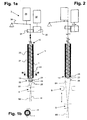
- FIG. 1 a shows a device V according to the invention in a state during the filling of a bag B 1.
- the device V has a filling tube 1, which is designed substantially hollow cylindrical.
- the entire filling tube 1 is designed as a hollow cylinder.
- Other shapes are possible, but at least one lower outlet region 14 is formed as a hollow cylinder.
- the filling tube 1 is aligned vertically. This corresponds to the preferred arrangement.
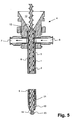
- the filling tube 1 has an upper inlet opening 10 and a lower outlet opening 11. As is visible in FIG. 5, the inlet opening 10 opens into a filling funnel 12. By means of this filling funnel 12 pourable material can be introduced into the filling tube 1.
- the bulk material is filled into vertically produced tubular bags B1, B2.
- the tube H is withdrawn along the lower outlet opening 11 and this enclosing.
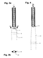
- the desired cutting of a filled bag B2 is achieved by means of sealing jaws S, which in the example shown here are movable in the vertical direction and remove the individual bags after filling. Their movement is shown in Figure 2 with a double arrow.
- a metering element 2 here a metering screw arranged. It is movable along a longitudinal axis L of the filling tube 1 and rotatable about its own longitudinal axis.
- metering element 2 here a metering screw arranged. It is movable along a longitudinal axis L of the filling tube 1 and rotatable about its own longitudinal axis.
- the longitudinal and rotational movement of the metering element 21 can be achieved in various ways.
- the person skilled in the art is well-known for this purpose.
- a lifting and rotation unit 3 is shown schematically. It comprises a rotary drive 32, for example a servomotor, a first and a second gearwheel 30, 31 connected thereto and a lifting drive 33, eg a servomotor, which acts on a pivoting lever 34 mounted on one side.
- the metering element 2 has a closing head 22 at its lower end adjacent to the outlet opening. This protrudes in the filling position, i. in the position in which the outlet opening 11 is released on the lower side of the filling tube 1 out of this. This position is shown in Figures 1a and 3a.
- the closing head 22 has at least one, here exactly one closing area 23 with a cylindrical lateral surface, i. a cylindrical outer surface, on.
- this closing area is circular-cylindrical and extends over a length of 0.2 to 10 mm at a diameter of the closing head 22 at this point of 5 to 60 mm.
- the closing area 23 can be designed as a sealing flange and be provided with a sealing ring or another sealing element. The sealing flange can, but does not necessarily have to rest against the hollow-cylindrical outlet region 14 of the filling tube 1.
- the closing head 22 tapers above the closing area 23, i. to the interior of the filling tube 1, to a neck 24.
- this tapered portion or neck 24 is frusto-conical.
- other shapes for example a concave or convex outer surface of the tapered portion 24, are also possible.
- the upper tapered region 24 preferably has a diameter which is at most half the diameter of the cylindrical closing region 23.
- the closing head 22 also tapers below the closing area 23, i. outwardly.
- a conical shape is preferred, such as a truncated cone or a cone.
- other shapes such as convex or concave lateral surfaces, are not excluded.
- the metering element 2 is a metering screw. It has a shaft 20 and at least one helically extending over at least approximately the entire length of the shaft 20 extending screw flight 21.
- the screw 2 at least in its lower region an outer Diameter up, measured to the outer edge of the screw winding, which is at least approximately equal to or only a few percent smaller than the outer diameter of the closing portion 23.
- the diameter of the shaft 24 preferably corresponds at least in the lower region of the smallest diameter of the upper tapered portion 24th ,
- the metering element 21 may have a shaft, at the lower, the outlet opening 11 facing region of the shaft projecting flange is arranged, which at least approximately bridges the distance between the shaft and inner wall of the filling tube 1.
- this flange preferably extends only over a part of the outer circumference of the shaft 20.
- the flange may be arranged on the shaft 20 or above the closing area 23 on the closing head 22.
- the metering element 2 rotates while the bulk material is being filled into the bag B1. Thanks to the tapered upper portion 24, the bulk material is distributed evenly, hurling the bulk material into both corner regions of the bag (see Figures 1b and 3b).
- the rotational movement is stopped and the dosing element 2 is raised.
- the tapered upper portion 24 facilitates the lifting.
- the lifting and rotating movements are thus carried out intermittently.
- the raised position is shown in FIGS. 2 and 4.
- FIG. 5 shows a further aspect of the device according to the invention, which could also be used without the cylindrical closing head 23.
- the filling tube 1 is here provided with at least one air conditioning duct 5, which cools or heats the bulk material located in the tube 1. Cooling, in particular water cooling, is preferred.
- the air-conditioning duct 5 can be designed differently. It can spiral around the tube 1, extend radially or axially around the tube 1 in several subchannels or, as shown here, can be formed as an annular gap which extends at least approximately over the entire length of the filling tube 1. In the latter case, an outer with respect to the filling tube 1 coaxial cooling tube can be used.
- the filling tube itself can also be double-walled, as shown here.
- the temperature influence of the bulk material can preferably be achieved by water, which is passed through the air conditioning duct 5.
- a feed channel 6 and a corresponding discharge channel 7 are present in the area of an upper flange-on means 4 of the filling pipe 1, which are both connected to the air-conditioning duct 5.
- the device according to the invention thus enables a quick and well-defined closure of the outlet opening and offers self-cleaning when opening.
Landscapes
- Engineering & Computer Science (AREA)
- Mechanical Engineering (AREA)
- Basic Packing Technique (AREA)
- Supply Of Fluid Materials To The Packaging Location (AREA)
Description
- Die Erfindung betrifft eine Vorrichtung zum dosierten Abfüllen von Schüttgut gemäss Oberbegriff des Patentanspruchs 1.
- Derartige Vorrichtungen weisen ein vertikal verlaufendes Füllrohr mit einer darin in axialer Richtung bewegbaren und rotierbaren Dosierschnecke auf. In Beutel oder anderweitige Behälter abzufüllendes Schüttgut wird oben in das Füllrohr eingefüllt und mittels der Dosierschnecke in dosierten Portionen am unteren Ende des Füllrohrs in die Beutel gefördert. Zur Unterbrechung des Flusses und Portionierung lässt sich das untere Ende des Füllrohrs mit einem Verschlussmittel verschliessen.
- Es sind Vorrichtungen bekannt, bei welchen ein von der Dosierschnecke unabhängiges Verschlussmittel verwendet wird. Beispiele hierfür sind in
EP-A-0'201'777 ,CH-A-690'572 DE-A-195'19'682 gegeben. Diese weisen den Nachteil auf, dass die Verschlussmittel eine separate Steuerung benötigen und zudem im Auslassbereich des Füllrohrs Platz beanspruchen. - In anderen Vorrichtungen ist das Verschlussmittel integraler Bestandteil der Dosierschnecke. So offenbart
DE-A-102'21'567 eine Vorrichtung, bei welcher die Dosierschnecke einen kegelstumpfförmigen Schliesskopf mit einer Dichtung aufweist. Im angehobenen Zustand der Dosierschnecke liegt diese Dichtung an der unteren Stirnfläche des Füllrohrs an. -
EP-A-0'967'149 zeigt eine Dosierschnecke mit einem doppelkegelförmigen Schliesskopf, wobei dieser im abgesenkten Zustand an einer konischen Innenfläche des Füllrohrs aufliegt und somit die Auslassöffnung verschliesst. - Auch bei
EP-A-0'808'795 liegt der kegelförmige Schliesskopf im abgesenkten Zustand im Bereich der Auslassöffnung des Füllrohrs an dessen Innenfläche auf. BeiUS-A-3'486'664 liegt er hingegen im angehobenen Zustand an. - Bei diesen Vorrichtungen neigt das Schüttgut dazu, sich im Auslassbereich an der Innenwand des Füllrohrs abzulagern und zu verklumpen. Derartige Verklumpungen stören jedoch den weiteren Fluss und somit auch die genaue Dosierung. Die Ablagerungen verhindern zudem eine vollständige Schliessung der Auslassöffnung.
-
EP-A-0'514'770 offenbart eine Vorrichtung zur Förderung von Pasten, wobei die Vorrichtung eine Förderschnecke aufweist, welche an ihrem unteren Ende in einem konusförmigen Lager gelagert ist. -
US 2003/0155382 zeigt zylindrische Bereiche in Füllrohr und Schliesskopf, diese bilden aber nicht den eigentlichen Schliessbereich. - Es ist eine Aufgabe der Erfindung, eine Vorrichtung zu schaffen, welche die oben genannten Nachteile behebt.
- Diese Aufgabe löst eine Vorrichtung mit den Merkmalen des Patentanspruchs 1.
- Die erfindungsgemässe Vorrichtung weist ein Füllrohr und ein im Füllrohr rotierbares Dosierelement auf, wobei das Dosierelement entlang einer Längsachse des Füllrohrs bewegbar ist und wobei das Dosierelement einen Schliesskopf zum Verschluss eines unteren Auslassbereichs des Füllrohrs aufweist. Der Schliesskopf weist dabei erfindungsgemäss mindestens einen Schliessbereich mit einer zylindrischen Mantelfläche auf. Als Gegenstück dazu ist das Füllrohr mindestens im Auslassbereich hohlzylinderförmig ausgebildet.
- Diese Ausbildung des Schliesskopfes und des Auslassbereichs ermöglicht eine schnelle Schliessung der Auslassöffnung, ohne dass grosse Distanzen überwunden werden müssen. Zudem ist der Platzbedarf äusserst gering.
- Des weiteren erlaubt diese Ausbildung eine Selbstreinigung des Auslassbereichs des Füllrohrs. Dadurch lassen sich Ablagerungen entfernen, die Schliessqualität bleibt erhalten und die Dosiergenauigkeit gewährleistet. Trotzdem erhöhen Mittel, welche zur Selbstreinigung verwendet werden, den Platzbedarf der Vorrichtung im Füllbereich der Beutel nicht. Dies ist insbesondere dann der Fall, wenn das Dosierelement als Dosierschnecke mit einer Welle und mindestens einer entlang dieser verlaufenden Schneckenwindung ausgebildet ist.
- In einer bevorzugten Ausführungsform geht der mindestens eine Schliessbereich nach oben in einen relativ zu ihm verjüngten oberen Bereich über. Dadurch wird eine gleichmässige Verteilung des Schüttguts beim Abfüllen in den Beutel erzielt. Zudem erleichtert diese obere Verjüngung das Einfahren des Schliesskopfes in das Füllrohr, wenn das Dosierelement zum verschliessen der Auslassöffnung angehoben wird.
- Vorzugsweise geht der mindestens eine zylinderförmig ausgebildete Schliessbereich auch nach unten in einen verjüngten unteren Bereich über. Dadurch beansprucht der Schliesskopf einen minimalen Raum innerhalb des zu befüllenden Beutels und das Eintauchen des Schliesskopfes in den Beutel wird erleichtert.
- In einer bevorzugten Ausführungsform verfügt die Vorrichtung über eine Klimaeinheit zum Kühlen bzw. Wärmen des Schüttguts. Je nach Art des Schüttguts erhöht dies die Genauigkeit der Dosierung, da sich mit der Temperatur beispielsweise die Rieselfähigkeit und die Adhäsionseigenschaften ändern.
- Weitere vorteilhafte Ausführungsformen gehen aus den abhängigen Patentansprüchen hervor.
- Im folgenden wird der Erfindungsgegenstand anhand eines bevorzugten Ausführungsbeispiels, welches in den beiliegenden Zeichnungen dargestellt ist, erläutert. Es zeigen:
- Figur 1a
- eine schematische Darstellung einer erfindungsgemässen Vorrichtung im abgesenkten Zustand des Dosierelements von einer ersten Seite;
- Figur 1b
- einen Schnitt entlang B-B gemäss Figur 1a;
- Figur 2
- die Vorrichtung gemäss Figur 1 a mit angehobenem Dosierelement;
- Figur 3a
- die Vorrichtung gemäss Figur 1a mit abgesenktem Dosierelement von einer zweiten Seite;
- Figur 3b
- einen Schnitt entlang A-A gemäss Figur 3a;
- Figur 4
- die Vorrichtung gemäss Figur 3a mit angehobenem Dosierelement und
- Figur 5
- einen Längsschnitt durch die Vorrichtung gemäss Figur 1 a.
- Die erfindungsgemässe Vorrichtung eignet sich für alle Schüttgüter, insbesondere jedoch für Schüttgüter mit relativ kleinen Korngrössen von einigen wenigen Hundertstel bis einigen Zehntel Millimeter Durchmesser. Vorzugsweise wird die Vorrichtung zum Abfüllen von Schüttgut im Medizinal- und im Lebensmittelbereich eingesetzt, beispielsweise zum Abfüllen von pulverförmigen Medikamenten, Zucker oder Gewürzen. Das Schüttgut wird vorzugsweise in Beutel, insbesondere von vertikal erzeugten Schlauchbeuteln oder Siegelrandbeuteln, abgepackt. Es lassen sich jedoch auch andere Verpackungstypen einsetzen.
- In Figur 1a ist eine erfindungsgemässe Vorrichtung V in einem Zustand während des Befüllens eines Beutels B 1 dargestellt. Die Vorrichtung V weist ein Füllrohr 1 auf, welches im wesentlichen hohlzylinderförmig ausgestaltet ist. Hier ist das gesamte Füllrohr 1 als Hohlzylinder gestaltet. Andere Formen sind möglich, wobei jedoch mindestens ein unterer Auslassbereich 14 hohlzylinderförmig ausgebildet ist.
- Im hier dargestellten Beispiel ist das Füllrohr 1 vertikal stehend ausgerichtet. Dies entspricht der bevorzugten Anordnung. Das Füllrohr 1 weist eine obere Einlassöffnung 10 und eine untere Auslassöffnung 11 auf Die Einlassöffnung 10 mündet, wie in Figur 5 sichtbar ist, in einen Einfülltrichter 12. Durch diesen Einfülltrichter 12 lässt sich schüttfähiges Material in das Füllrohr 1 einfüllen.
- Im dargestellten Beispiel wird das Schüttgut in vertikal erzeugte Schlauchbeutel B1, B2 abgefüllt. Der Schlauch H wird entlang der unteren Auslassöffnung 11 und diese umschliessend abgezogen. Die gewünschte Ablängung eines gefüllten Beutels B2 wird mittels Siegelbacken S erzielt, welche im hier dargestellten Beispiel in vertikaler Richtung bewegbar sind und die einzelnen Beutel nach dem Befüllen abziehen. Ihre Bewegung ist in Figur 2 mit einem Doppelpfeil dargestellt.
- Im Füllrohr 1 ist ein Dosierelement 2, hier eine Dosierschnecke, angeordnet. Es ist entlang einer Längsachse L des Füllrohrs 1 bewegbar und um seine eigene Längsachse drehbar. Es lassen sich jedoch auch anders geformte Dosierelemente und insbesondere auch nicht rotierende Dosierelemente verwenden.
- Die Längs- und Rotationsbewegung des Dosierelements 21 lässt sich auf verschiedene Arten erreichen. Dem Fachmann sind hierzu hinlänglich Mittel bekannt. In den Figuren 1a und 2 ist deshalb lediglich schematisch eine Hub- und Rotationseinheit 3 dargestellt. Sie umfasst einen Rotationsantrieb 32, z.B. ein Servomotor, ein damit verbundenes erstes und eine zweites Zahnrad 30, 31 und einen Hubantrieb 33, z.B. ein Servomotor, welcher auf einen einseitig gelagerten Schwenkhebel 34 wirkt.
- Das Dosierelement 2 weist an seinem unteren, der Auslassöffnung benachbarten Ende einen Schliesskopf 22 auf. Dieser ragt in der Befüllposition, d.h. in der Position, in welcher die Auslassöffnung 11 freigegeben ist, auf der unteren Seite des Füllrohrs 1 aus diesem heraus. Diese Position ist in den Figuren 1a und 3 a dargestellt.
- Der Schliesskopf 22 weist mindestens einen, hier genau einen Schliessbereich 23 mit einer zylinderförmigen Mantelfläche, d.h. einer zylinderförmigen äusseren Oberfläche, auf. Vorzugsweise ist dieser Schliessbereich kreiszylinderförmig ausgebildet und erstreckt sich über eine Länge von 0.2 bis 10 mm bei einem Durchmesser des Schliesskopfes 22 an dieser Stelle von 5 bis 60 mm. Der Schliessbereich 23 kann als Dichtflansch ausgebildet und mit einem Dichtring oder einem anderen Dichtelement versehen sein. Der Dichtflansch kann, muss jedoch nicht zwingend am hohlzylinderförmig ausgebildeten Auslassbereich 14 des Füllrohrs 1 anliegen.
- Vorzugsweise verjüngt sich der Schliesskopf 22 oberhalb des Schliessbereichs 23, d.h. zum Innern des Füllrohrs 1 hin, zu einem Hals 24. Im hier dargestellten Beispiel ist dieser verjüngte Bereich oder Hals 24 kegelstumpfförmig ausgebildet. Andere Formen, beispielsweise eine konkav oder konvex ausgebildete Mantelfläche des verjüngten Bereichs 24, sind jedoch auch möglich. Der obere verjüngte Bereich 24 weist vorzugsweise einen Durchmesser auf, welcher maximal die Hälfte des Durchmessers des zylinderförmigen Schliessbereichs 23 beträgt.
- Vorzugsweise verjüngt sich der Schliesskopf 22 auch unterhalb des Schliessbereichs 23, d.h. nach aussen hin. Auch hier ist eine konische Form bevorzugt, beispielsweise ein Kegelstumpf oder ein Kegel. Es sind jedoch auch andere Formen, beispielsweise konvexe oder konkave Mantelflächen, nicht ausgeschlossen.
- In einer bevorzugten Ausführungsform ist das Dosierelement 2 eine Dosierschnecke. Sie verfügt über eine Welle 20 und mindestens eine sich spiralförmig über mindestens annähernd die gesamte Länge der Welle 20 erstreckende Schneckenwindung 21. Vorzugsweise weist die Schnecke 2 mindestens in ihrem unteren Bereich einen äusseren Durchmesser auf, gemessen bis zur äusseren Kante der Schneckenwindung, welcher mindestens annähernd gleich gross oder nur um wenige Prozente kleiner ist als der äussere Durchmesser des Schliessbereichs 23. Der Durchmesser der Welle 24 entspricht vorzugsweise zumindest im unteren Bereich dem kleinsten Durchmesser des oberen verjüngten Bereichs 24.
- Andere Formen von Dosierelementen lassen sich jedoch auch verwenden. So kann das Dosierelement 21 beispielsweise eine Welle aufweisen, an deren unterem, der Auslassöffnung 11 zugewandten Bereich ein der Welle vorstehender Flansch angeordnet ist, welcher den Abstand zwischen Welle und Innenwandung des Füllrohrs 1 mindestens annähernd überbrückt. Dieser Flansch erstreckt sich jedoch vorzugsweise nur über einen Teil des äusseren Umfangs der Welle 20. Der Flansch kann an der Welle 20 oder oberhalb des Schliessbereichs 23 am Schliesskopf 22 angeordnet sein.
- In der Position gemäss den Figuren 1a und 3a dreht sich das Dosierelement 2, während das Schüttgut in den Beutel B1 abgefüllt wird. Dank des verjüngten oberen Bereichs 24 wird das Schüttgut gleichmässig verteilt, wobei es das Schüttgut in beide Eckbereiche des Beutels (siehe Figuren 1b und 3b) schleudert.
- Ist die gewünschte Dosierung erreicht, wird die Rotationsbewegung gestoppt und das Dosierelement 2 angehoben. Der verjüngte obere Bereich 24 erleichtert dabei die Anhebung. Die Hub- und Rotationsbewegungen werden somit intermittierend ausgeführt. Die angehobene Position ist in den Figuren 2 und 4 dargestellt. Durch Anlage des zylinderförmigen Schliessbereichs 23 an die zylinderförmige Innenwandung 13 des Füllrohrs 1 im Auslassbereich 14 ist ein Unterbruch des Schüttgutstroms gewährleistet. Die Bewegung kann aufgrund des kurzen Weges und ihrer Einfachheit relativ schnell ausgeführt werden, so dass ein gezieltes Unterbrechen und somit Dosieren ermöglicht ist und der Abfüllvorgang lediglich während einer minimalen Zeitspanne unterbrochen werden muss. Dies optimiert die Leistungsfähigkeit der Vorrichtung und ihre Produktivität.
- Beim erneuten Absenken des Dosierelements 2 in den nächstfolgenden zu befüllenden Schlauchbeutel B1 erleichtert der untere verjüngte Bereich 25 die Einführung in den Beutel B1. Des weiteren wird der untere Auslassbereich 14 zugleich von allfälligen Schüttgutablagerungen, welche sich an der Innenwand des Füllrohrs 1 angesetzt haben könnten, gereinigt. Dies wird vor allem durch den unteren Bereich der Schneckenwindung 21 oder im Falle eines Flansches durch diesen erzielt. Diese Selbstreinigung kann auch durch andere der Welle vorstehende Mittel zur Selbstreinigung erzielt werden, beispielsweise indem der Schliesskopf zwei oder mehr über einander angeordnete zylinderförmige Bereiche aufweist.
- In Figur 5 ist ein weiterer Aspekt der erfindungsgemässen Vorrichtung dargestellt, welcher sich auch ohne den zylinderförmigen Schliesskopf 23 verwenden lassen könnte. Das Füllrohr 1 ist hier mit mindestens einem Klimakanal 5 versehen, welcher das im Rohr 1 befindliche Schüttgut kühlt bzw. wärmt. Eine Kühlung, insbesondere eine Wasserkühlung, ist bevorzugt. Der Klimakanal 5 kann verschieden ausgebildet sein. Er kann sich spiralförmig um das Rohr 1 wickeln, in mehreren Teilkanälen radial oder axial um das Rohr 1 verlaufen oder wie hier dargestellt als Ringspalt ausgebildet sein, welcher sich mindestens annähernd über die gesamte Länge des Füllrohrs 1 erstreckt. Im letzteren Fall kann ein äusseres bezüglich des Füllrohrs 1 koaxiales Kühlrohr verwendet werden. Das Füllrohr selber kann auch, wie hier dargestellt, doppelwandig ausgebildet sein.
- Die Temperaturbeeinflussung des Schüttguts lässt sich vorzugsweise durch Wasser erzielen, welches durch den Klimakanal 5 geleitet wird. Hierzu ist im Bereich eines oberen Anflanschmittels 4 des Füllrohrs 1 ein Zuführkanal 6 und ein entsprechender Abführkanal 7 vorhanden, welche beide mit dem Klimakanal 5 verbunden sind.
- Die erfindungsgemässe Vorrichtung ermöglicht somit eine schnelle und wohldefinierte Schliessung der Auslassöffnung und bietet beim Öffnen eine Selbstreinigung.
Claims (10)
- Vorrichtung zum dosierten Abfüllen von Schüttgut, wobei die Vorrichtung ein Füllrohr (1) und ein darin angeordnetes Dosierelement (2) aufweist, das entlang einer Längsachse (A) des Füllrohrs (1) bewegbar ist und einen Schliesskopf (22) zum Verschluss eines unteren Auslassbereichs (14) des Füllrohrs (1) aufweist, dadurch gekennzeichnet, dass der Schliesskopf (22) mindestens einen Schliessbereich (23) mit einer zylindrischen Mantelfläche aufweist und dass das Füllrohr (1) mindestens im Auslassbereich (14) hohlzylinderförmig ausgebildet ist, wobei die zylindrischen Bereiche in Schliessstellung einander überlappen.
- Vorrichtung nach Anspruch 1, wobei das Dosierelement (2) eine Dosierschnecke mit einer Welle (20) und mindestens einer entlang dieser Welle verlaufenden Schneckenwindung (21) ist.
- Vorrichtung nach einem der Ansprüche 1 oder 2, wobei der mindestens eine Schliessbereich (23) nach oben in einen relativ zu ihm oberen verjüngten Bereich (24) übergeht.
- Vorrichtung nach Anspruch 3, wobei der obere verjüngte Bereich (24) kegelstumpfförmig ist oder eine konische oder konkav ausgebildete Mantelfläche aufweist.
- Vorrichtung nach einem der Ansprüche 1 bis 4, wobei der mindestens eine Schliessbereich (23) als Dichtfläche ausgebildet ist und vorzugsweise mit einem Dichtelement versehen ist.
- Vorrichtung nach einem der Ansprüche 1 bis 5, wobei sich der Schliesskopf (22) auf beiden Seiten des mindestens einen Schliessbereichs (23) verjüngt.
- Vorrichtung nach Anspruch 2, wobei die Welle (20) mindestens annähernd denselben Durchmesser aufweist wie der obere verjüngte Bereich (24) an seinem oberen Ende.
- Vorrichtung nach einem der Ansprüche 1 bis 7, wobei das Dosierelement (2) rotierbar ist.
- Vorrichtung nach einem der Ansprüche 1 bis 8, wobei das Füllrohr (1) mindestens einen Klimakanal (5), insbesondere für eine Wasserkühlung, aufweist.
- Vorrichtung nach Anspruch 9, wobei der mindestens eine Klimakanal (5) das Dosierelement (2) umgibt und sich mindestens annähernd über die gesamte Länge des Füllrohrs (1) erstreckt.
Applications Claiming Priority (2)
| Application Number | Priority Date | Filing Date | Title |
|---|---|---|---|
| CH5662004 | 2004-04-01 | ||
| CH5662004 | 2004-04-01 |
Publications (2)
| Publication Number | Publication Date |
|---|---|
| EP1582467A1 EP1582467A1 (de) | 2005-10-05 |
| EP1582467B1 true EP1582467B1 (de) | 2007-08-29 |
Family
ID=34866035
Family Applications (1)
| Application Number | Title | Priority Date | Filing Date |
|---|---|---|---|
| EP05101280A Expired - Lifetime EP1582467B1 (de) | 2004-04-01 | 2005-02-21 | Vorrichtung zum dosierten Abfüllen von Schüttgut |
Country Status (5)
| Country | Link |
|---|---|
| EP (1) | EP1582467B1 (de) |
| JP (1) | JP4944385B2 (de) |
| AT (1) | ATE371584T1 (de) |
| DE (1) | DE502005001342D1 (de) |
| ES (1) | ES2289651T3 (de) |
Cited By (1)
| Publication number | Priority date | Publication date | Assignee | Title |
|---|---|---|---|---|
| WO2011051066A1 (de) | 2009-11-02 | 2011-05-05 | Robert Bosch Gmbh | Vorrichtung zum dosierten abfüllen von schüttgut |
Families Citing this family (10)
| Publication number | Priority date | Publication date | Assignee | Title |
|---|---|---|---|---|
| DE102005046627A1 (de) * | 2005-09-29 | 2007-04-05 | Robert Bosch Gmbh | Dosiereinheit zum Dosieren eines Substrats |
| US8141751B2 (en) * | 2005-10-03 | 2012-03-27 | Mettler-Toledo Ag | Dosage-dispensing device for substances in powder-or paste form |
| DE102005048176B4 (de) * | 2005-10-06 | 2018-06-14 | S.S.T.-Schüttguttechnik GmbH | Dosiervorrichtung mit einem Förderkanal und Dosierverfahren |
| CN102633001A (zh) * | 2012-05-02 | 2012-08-15 | 无锡市耐特机电一体化技术有限公司 | 带搅拌机构的物料装袋装置 |
| CN103587736B (zh) * | 2013-11-06 | 2015-11-18 | 瑞安市恺鸿包装机械有限公司 | 一种加料机 |
| CN103921964B (zh) * | 2014-05-04 | 2017-01-04 | 上海陆达包装机械制造有限公司 | 一种新型的超细粉包装机 |
| CN107074383B (zh) | 2014-10-15 | 2019-08-27 | I.M.A.工业机械自动化股份公司 | 用于向滤袋进给和按剂量分配浸泡或萃取产品的设备和方法 |
| IT201700045807A1 (it) | 2017-04-28 | 2017-07-28 | Hero Europe S R L | Dispositivo, sistema di dosaggio per prodotti in polvere, liquidi, pastosi o cremosi e macchina dispensatrice comprendente tale dispositivo |
| WO2020165165A1 (en) | 2019-02-11 | 2020-08-20 | Gea Process Engineering Nv | A feeder device for feeding a powder material |
| DE102020113955B4 (de) | 2020-05-25 | 2022-06-23 | Syntegon Technology Gmbh | Vorrichtung zum Mischen und Dosieren von Substanzen und Verfahren zum Betrieb einer solchen Vorrichtung |
Family Cites Families (11)
| Publication number | Priority date | Publication date | Assignee | Title |
|---|---|---|---|---|
| DE2803310A1 (de) * | 1978-01-26 | 1979-08-02 | Hick & Co Gmbh | Dosiereinrichtung fuer abfuellanlagen |
| JPS6191508A (ja) * | 1984-10-12 | 1986-05-09 | Sumitomo Metal Ind Ltd | 表面欠陥検出装置 |
| JPS6191507A (ja) * | 1984-10-12 | 1986-05-09 | Sumitomo Metal Ind Ltd | 傾斜角測定装置 |
| DE3605245A1 (de) * | 1986-02-19 | 1987-08-20 | Bosch Gmbh Robert | Dosier- und abfuellvorrichtung fuer fliessfaehiges gut |
| JPH01240424A (ja) * | 1988-03-10 | 1989-09-26 | Shin Etsu Chem Co Ltd | 流体の充填方法及びその装置 |
| JP3973000B2 (ja) * | 1998-02-10 | 2007-09-05 | 株式会社南陽 | 化粧剤の充填用ノズル |
| DE19962475C5 (de) * | 1999-12-24 | 2009-09-24 | Erin Intellectual Property Ltd., Birr | Verfahren und Vorrichtung zur Befüllung eines Sackes |
| US6244309B1 (en) * | 2000-07-06 | 2001-06-12 | Wendell S. Martin | Rugged high flow rate valve for bottle filling machines |
| DE50204173D1 (de) * | 2002-02-20 | 2005-10-13 | Bmh Chronos Richardson Gmbh | Verfahren und Vorrichtung zum Dosieren von Schüttgut |
| DE10221567B4 (de) * | 2002-05-15 | 2007-06-21 | Bmh Chronos Richardson Gmbh | Verfahren und Vorrichtung zum Befüllen eines Sackes mit Luftabsaugung |
| JP4125050B2 (ja) * | 2002-06-19 | 2008-07-23 | 株式会社東京自働機械製作所 | 粉粒体供給装置 |
-
2005
- 2005-02-21 EP EP05101280A patent/EP1582467B1/de not_active Expired - Lifetime
- 2005-02-21 ES ES05101280T patent/ES2289651T3/es not_active Expired - Lifetime
- 2005-02-21 DE DE502005001342T patent/DE502005001342D1/de not_active Expired - Lifetime
- 2005-02-21 AT AT05101280T patent/ATE371584T1/de not_active IP Right Cessation
- 2005-04-01 JP JP2005106634A patent/JP4944385B2/ja not_active Expired - Fee Related
Cited By (2)
| Publication number | Priority date | Publication date | Assignee | Title |
|---|---|---|---|---|
| WO2011051066A1 (de) | 2009-11-02 | 2011-05-05 | Robert Bosch Gmbh | Vorrichtung zum dosierten abfüllen von schüttgut |
| DE102009046288A1 (de) | 2009-11-02 | 2011-05-05 | Robert Bosch Gmbh | Vorrichtung zum dosierten Abfüllen von Schüttgut |
Also Published As
| Publication number | Publication date |
|---|---|
| ATE371584T1 (de) | 2007-09-15 |
| EP1582467A1 (de) | 2005-10-05 |
| JP2005289517A (ja) | 2005-10-20 |
| ES2289651T3 (es) | 2008-02-01 |
| JP4944385B2 (ja) | 2012-05-30 |
| DE502005001342D1 (de) | 2007-10-11 |
Similar Documents
| Publication | Publication Date | Title |
|---|---|---|
| EP1931950B1 (de) | Dosiereinrichtung für pulver- oder pastenförmige substanzen | |
| EP2059464B1 (de) | Vorrichtung zum austragen von länglichen, grobschüttfähigen produkte | |
| EP2794462B1 (de) | Füllelement sowie füllsystem | |
| EP1582467B1 (de) | Vorrichtung zum dosierten Abfüllen von Schüttgut | |
| EP2218331B1 (de) | Mischvorrichtung für Lebensmittel-Massen wie Wurstbrät sowie Füllmaschine | |
| EP4281395B1 (de) | System zum transport von sterilen schüttfähigen verschlusselementen | |
| EP2065174B1 (de) | Füllvorrichtung für eine Rundlauf-Tablettenpresse | |
| EP0897864A2 (de) | Vorrichtung und Verfahren zum dosierten Abfüllen von flüssigen bis pastösen Produkten | |
| DE19929180C2 (de) | Beschickungsvorrichtung für einen Schachtofen | |
| EP2458345A1 (de) | Dosiervorrichtung | |
| EP1931952B1 (de) | Dosiereinrichtung für pulver- oder pastenförmige substanzen | |
| EP3041746B1 (de) | Vorrichtung zur steuerung der durchflussmenge | |
| DE19706407C1 (de) | Dosier- und Austragsvorrichtung für Schüttgüter | |
| DE19918711A1 (de) | Darmführungsrohr mit Begrenzung der Darmspannung von Naturdärmen | |
| EP2496478B1 (de) | Vorrichtung zum dosierten abfüllen von schüttgut | |
| DE1757225B1 (de) | Vorrichtung zum Einhuellen eines eine Fuellung bildenden Nahrungsmittels in ein elastisches,teigartiges Material | |
| EP3523201B1 (de) | Fülleinrichtung für eine packmaschine zum füllen von schüttgütern in gebinde | |
| EP3270747B1 (de) | Kaffeevollautomat mit einer einrichtung zur portionierung von kaffeebohnen | |
| AT506464B1 (de) | Vorrichtung zum befüllen eines lagerraumes mit stückeligem brennstoff | |
| DE8808369U1 (de) | Drehverschluß für Behälter | |
| WO2020156946A1 (de) | Mischwerkzeug für eine industrielle mischmaschine, mischwerkzeugsatz mit derartigen mischwerkzeugen sowie mischmaschine mit einem solchen mischwerkzeugsatz | |
| DE19749917A1 (de) | Verfahren und Vorrichtung zum Dosieren | |
| DE4420084C1 (de) | Vorrichtung zum Einfüllen von stückchenförmigem Lebensmittel-Füllgut in becherförmige Behälter von ein- oder mehrbahnigen Lebensmittel-Abfüllvorrichtungen | |
| DE102024107822A1 (de) | Dosiervorrichtung für ein Schüttgut und Verfahren zum Einstellen und/oder zur Steuerung der Abgabe eines Schüttgutes und/oder der Größe eines Schüttgutstromes, insbesondere zum Dosieren des Schüttgutes | |
| DE102004035924A1 (de) | Dosier-und/oder Abfüllvorrichtung für fließfähiges Schüttgut |
Legal Events
| Date | Code | Title | Description |
|---|---|---|---|
| PUAI | Public reference made under article 153(3) epc to a published international application that has entered the european phase |
Free format text: ORIGINAL CODE: 0009012 |
|
| AK | Designated contracting states |
Kind code of ref document: A1 Designated state(s): AT BE BG CH CY CZ DE DK EE ES FI FR GB GR HU IE IS IT LI LT LU MC NL PL PT RO SE SI SK TR |
|
| AX | Request for extension of the european patent |
Extension state: AL BA HR LV MK YU |
|
| 17P | Request for examination filed |
Effective date: 20060405 |
|
| AKX | Designation fees paid |
Designated state(s): AT BE BG CH CY CZ DE DK EE ES FI FR GB GR HU IE IS IT LI LT LU MC NL PL PT RO SE SI SK TR |
|
| GRAP | Despatch of communication of intention to grant a patent |
Free format text: ORIGINAL CODE: EPIDOSNIGR1 |
|
| RIN1 | Information on inventor provided before grant (corrected) |
Inventor name: ALTERMATT, WILLY |
|
| GRAS | Grant fee paid |
Free format text: ORIGINAL CODE: EPIDOSNIGR3 |
|
| GRAA | (expected) grant |
Free format text: ORIGINAL CODE: 0009210 |
|
| AK | Designated contracting states |
Kind code of ref document: B1 Designated state(s): AT BE BG CH CY CZ DE DK EE ES FI FR GB GR HU IE IS IT LI LT LU MC NL PL PT RO SE SI SK TR |
|
| REG | Reference to a national code |
Ref country code: GB Ref legal event code: FG4D Free format text: NOT ENGLISH |
|
| REG | Reference to a national code |
Ref country code: CH Ref legal event code: NV Representative=s name: SCINTILLA AG, DIREKTION Ref country code: CH Ref legal event code: EP |
|
| REG | Reference to a national code |
Ref country code: IE Ref legal event code: FG4D Free format text: LANGUAGE OF EP DOCUMENT: GERMAN |
|
| REF | Corresponds to: |
Ref document number: 502005001342 Country of ref document: DE Date of ref document: 20071011 Kind code of ref document: P |
|
| GBT | Gb: translation of ep patent filed (gb section 77(6)(a)/1977) |
Effective date: 20071205 |
|
| PG25 | Lapsed in a contracting state [announced via postgrant information from national office to epo] |
Ref country code: IS Free format text: LAPSE BECAUSE OF FAILURE TO SUBMIT A TRANSLATION OF THE DESCRIPTION OR TO PAY THE FEE WITHIN THE PRESCRIBED TIME-LIMIT Effective date: 20071229 Ref country code: LT Free format text: LAPSE BECAUSE OF FAILURE TO SUBMIT A TRANSLATION OF THE DESCRIPTION OR TO PAY THE FEE WITHIN THE PRESCRIBED TIME-LIMIT Effective date: 20070829 Ref country code: NL Free format text: LAPSE BECAUSE OF FAILURE TO SUBMIT A TRANSLATION OF THE DESCRIPTION OR TO PAY THE FEE WITHIN THE PRESCRIBED TIME-LIMIT Effective date: 20070829 Ref country code: FI Free format text: LAPSE BECAUSE OF FAILURE TO SUBMIT A TRANSLATION OF THE DESCRIPTION OR TO PAY THE FEE WITHIN THE PRESCRIBED TIME-LIMIT Effective date: 20070829 |
|
| NLV1 | Nl: lapsed or annulled due to failure to fulfill the requirements of art. 29p and 29m of the patents act | ||
| REG | Reference to a national code |
Ref country code: ES Ref legal event code: FG2A Ref document number: 2289651 Country of ref document: ES Kind code of ref document: T3 |
|
| PG25 | Lapsed in a contracting state [announced via postgrant information from national office to epo] |
Ref country code: PL Free format text: LAPSE BECAUSE OF FAILURE TO SUBMIT A TRANSLATION OF THE DESCRIPTION OR TO PAY THE FEE WITHIN THE PRESCRIBED TIME-LIMIT Effective date: 20070829 |
|
| REG | Reference to a national code |
Ref country code: IE Ref legal event code: FD4D |
|
| ET | Fr: translation filed | ||
| PG25 | Lapsed in a contracting state [announced via postgrant information from national office to epo] |
Ref country code: GR Free format text: LAPSE BECAUSE OF FAILURE TO SUBMIT A TRANSLATION OF THE DESCRIPTION OR TO PAY THE FEE WITHIN THE PRESCRIBED TIME-LIMIT Effective date: 20071130 Ref country code: DK Free format text: LAPSE BECAUSE OF FAILURE TO SUBMIT A TRANSLATION OF THE DESCRIPTION OR TO PAY THE FEE WITHIN THE PRESCRIBED TIME-LIMIT Effective date: 20070829 |
|
| PG25 | Lapsed in a contracting state [announced via postgrant information from national office to epo] |
Ref country code: PT Free format text: LAPSE BECAUSE OF FAILURE TO SUBMIT A TRANSLATION OF THE DESCRIPTION OR TO PAY THE FEE WITHIN THE PRESCRIBED TIME-LIMIT Effective date: 20080129 Ref country code: IE Free format text: LAPSE BECAUSE OF FAILURE TO SUBMIT A TRANSLATION OF THE DESCRIPTION OR TO PAY THE FEE WITHIN THE PRESCRIBED TIME-LIMIT Effective date: 20070829 |
|
| PG25 | Lapsed in a contracting state [announced via postgrant information from national office to epo] |
Ref country code: SE Free format text: LAPSE BECAUSE OF FAILURE TO SUBMIT A TRANSLATION OF THE DESCRIPTION OR TO PAY THE FEE WITHIN THE PRESCRIBED TIME-LIMIT Effective date: 20071129 Ref country code: RO Free format text: LAPSE BECAUSE OF FAILURE TO SUBMIT A TRANSLATION OF THE DESCRIPTION OR TO PAY THE FEE WITHIN THE PRESCRIBED TIME-LIMIT Effective date: 20070829 |
|
| PLBE | No opposition filed within time limit |
Free format text: ORIGINAL CODE: 0009261 |
|
| STAA | Information on the status of an ep patent application or granted ep patent |
Free format text: STATUS: NO OPPOSITION FILED WITHIN TIME LIMIT |
|
| 26N | No opposition filed |
Effective date: 20080530 |
|
| BERE | Be: lapsed |
Owner name: ROBERT BOSCH G.M.B.H. Effective date: 20080228 |
|
| PG25 | Lapsed in a contracting state [announced via postgrant information from national office to epo] |
Ref country code: MC Free format text: LAPSE BECAUSE OF NON-PAYMENT OF DUE FEES Effective date: 20080228 |
|
| PG25 | Lapsed in a contracting state [announced via postgrant information from national office to epo] |
Ref country code: EE Free format text: LAPSE BECAUSE OF FAILURE TO SUBMIT A TRANSLATION OF THE DESCRIPTION OR TO PAY THE FEE WITHIN THE PRESCRIBED TIME-LIMIT Effective date: 20070829 |
|
| PG25 | Lapsed in a contracting state [announced via postgrant information from national office to epo] |
Ref country code: BE Free format text: LAPSE BECAUSE OF NON-PAYMENT OF DUE FEES Effective date: 20080228 |
|
| PG25 | Lapsed in a contracting state [announced via postgrant information from national office to epo] |
Ref country code: AT Free format text: LAPSE BECAUSE OF NON-PAYMENT OF DUE FEES Effective date: 20080221 |
|
| PG25 | Lapsed in a contracting state [announced via postgrant information from national office to epo] |
Ref country code: SI Free format text: LAPSE BECAUSE OF FAILURE TO SUBMIT A TRANSLATION OF THE DESCRIPTION OR TO PAY THE FEE WITHIN THE PRESCRIBED TIME-LIMIT Effective date: 20070829 |
|
| PG25 | Lapsed in a contracting state [announced via postgrant information from national office to epo] |
Ref country code: CY Free format text: LAPSE BECAUSE OF FAILURE TO SUBMIT A TRANSLATION OF THE DESCRIPTION OR TO PAY THE FEE WITHIN THE PRESCRIBED TIME-LIMIT Effective date: 20070829 |
|
| PG25 | Lapsed in a contracting state [announced via postgrant information from national office to epo] |
Ref country code: BG Free format text: LAPSE BECAUSE OF FAILURE TO SUBMIT A TRANSLATION OF THE DESCRIPTION OR TO PAY THE FEE WITHIN THE PRESCRIBED TIME-LIMIT Effective date: 20071129 |
|
| PG25 | Lapsed in a contracting state [announced via postgrant information from national office to epo] |
Ref country code: HU Free format text: LAPSE BECAUSE OF FAILURE TO SUBMIT A TRANSLATION OF THE DESCRIPTION OR TO PAY THE FEE WITHIN THE PRESCRIBED TIME-LIMIT Effective date: 20080301 Ref country code: LU Free format text: LAPSE BECAUSE OF NON-PAYMENT OF DUE FEES Effective date: 20080221 |
|
| REG | Reference to a national code |
Ref country code: FR Ref legal event code: PLFP Year of fee payment: 12 |
|
| REG | Reference to a national code |
Ref country code: FR Ref legal event code: PLFP Year of fee payment: 13 |
|
| REG | Reference to a national code |
Ref country code: FR Ref legal event code: PLFP Year of fee payment: 14 |
|
| PGFP | Annual fee paid to national office [announced via postgrant information from national office to epo] |
Ref country code: CH Payment date: 20180221 Year of fee payment: 14 |
|
| PGFP | Annual fee paid to national office [announced via postgrant information from national office to epo] |
Ref country code: DE Payment date: 20180426 Year of fee payment: 14 |
|
| REG | Reference to a national code |
Ref country code: DE Ref legal event code: R119 Ref document number: 502005001342 Country of ref document: DE |
|
| REG | Reference to a national code |
Ref country code: CH Ref legal event code: PL |
|
| PG25 | Lapsed in a contracting state [announced via postgrant information from national office to epo] |
Ref country code: CH Free format text: LAPSE BECAUSE OF NON-PAYMENT OF DUE FEES Effective date: 20190228 Ref country code: LI Free format text: LAPSE BECAUSE OF NON-PAYMENT OF DUE FEES Effective date: 20190228 |
|
| PG25 | Lapsed in a contracting state [announced via postgrant information from national office to epo] |
Ref country code: DE Free format text: LAPSE BECAUSE OF NON-PAYMENT OF DUE FEES Effective date: 20190903 |
|
| PGFP | Annual fee paid to national office [announced via postgrant information from national office to epo] |
Ref country code: TR Payment date: 20200218 Year of fee payment: 16 |
|
| REG | Reference to a national code |
Ref country code: GB Ref legal event code: 732E Free format text: REGISTERED BETWEEN 20201217 AND 20201223 |
|
| REG | Reference to a national code |
Ref country code: SK Ref legal event code: PC4A Ref document number: E 2584 Country of ref document: SK Owner name: SYNTEGON PACKAGING SYSTEMS AG, BERINGEN, CH Free format text: FORMER OWNER: ROBERT BOSCH GMBH, STUTTGART, DE Effective date: 20210118 |
|
| REG | Reference to a national code |
Ref country code: ES Ref legal event code: PC2A Owner name: SYNTEGON PACKAGING SYSTEMS AG Effective date: 20210311 Ref country code: ES Ref legal event code: PC2A Owner name: SYNTEGON PACKAGING SYSTEMS AG Effective date: 20210312 |
|
| PGFP | Annual fee paid to national office [announced via postgrant information from national office to epo] |
Ref country code: SK Payment date: 20220209 Year of fee payment: 18 Ref country code: CZ Payment date: 20220211 Year of fee payment: 18 |
|
| REG | Reference to a national code |
Ref country code: SK Ref legal event code: MM4A Ref document number: E 2584 Country of ref document: SK Effective date: 20230221 |
|
| PG25 | Lapsed in a contracting state [announced via postgrant information from national office to epo] |
Ref country code: CZ Free format text: LAPSE BECAUSE OF NON-PAYMENT OF DUE FEES Effective date: 20230221 |
|
| PG25 | Lapsed in a contracting state [announced via postgrant information from national office to epo] |
Ref country code: SK Free format text: LAPSE BECAUSE OF NON-PAYMENT OF DUE FEES Effective date: 20230221 |
|
| PGFP | Annual fee paid to national office [announced via postgrant information from national office to epo] |
Ref country code: ES Payment date: 20240319 Year of fee payment: 20 |
|
| PGFP | Annual fee paid to national office [announced via postgrant information from national office to epo] |
Ref country code: GB Payment date: 20240222 Year of fee payment: 20 |
|
| PGFP | Annual fee paid to national office [announced via postgrant information from national office to epo] |
Ref country code: IT Payment date: 20240229 Year of fee payment: 20 Ref country code: FR Payment date: 20240221 Year of fee payment: 20 |
|
| PG25 | Lapsed in a contracting state [announced via postgrant information from national office to epo] |
Ref country code: TR Free format text: LAPSE BECAUSE OF NON-PAYMENT OF DUE FEES Effective date: 20210221 |
|
| REG | Reference to a national code |
Ref country code: ES Ref legal event code: FD2A Effective date: 20250228 |
|
| REG | Reference to a national code |
Ref country code: GB Ref legal event code: PE20 Expiry date: 20250220 |
|
| PG25 | Lapsed in a contracting state [announced via postgrant information from national office to epo] |
Ref country code: ES Free format text: LAPSE BECAUSE OF EXPIRATION OF PROTECTION Effective date: 20250222 |
|
| PG25 | Lapsed in a contracting state [announced via postgrant information from national office to epo] |
Ref country code: GB Free format text: LAPSE BECAUSE OF EXPIRATION OF PROTECTION Effective date: 20250220 |