EP1580951A2 - Récepteur - Google Patents
Récepteur Download PDFInfo
- Publication number
- EP1580951A2 EP1580951A2 EP05251027A EP05251027A EP1580951A2 EP 1580951 A2 EP1580951 A2 EP 1580951A2 EP 05251027 A EP05251027 A EP 05251027A EP 05251027 A EP05251027 A EP 05251027A EP 1580951 A2 EP1580951 A2 EP 1580951A2
- Authority
- EP
- European Patent Office
- Prior art keywords
- channel
- frequency
- pilot
- interpolation filter
- estimate
- Prior art date
- Legal status (The legal status is an assumption and is not a legal conclusion. Google has not performed a legal analysis and makes no representation as to the accuracy of the status listed.)
- Granted
Links
Images

Classifications
-
- H—ELECTRICITY
- H04—ELECTRIC COMMUNICATION TECHNIQUE
- H04L—TRANSMISSION OF DIGITAL INFORMATION, e.g. TELEGRAPHIC COMMUNICATION
- H04L25/00—Baseband systems
- H04L25/02—Details ; arrangements for supplying electrical power along data transmission lines
- H04L25/03—Shaping networks in transmitter or receiver, e.g. adaptive shaping networks
- H04L25/03006—Arrangements for removing intersymbol interference
- H04L25/03159—Arrangements for removing intersymbol interference operating in the frequency domain
-
- H—ELECTRICITY
- H04—ELECTRIC COMMUNICATION TECHNIQUE
- H04L—TRANSMISSION OF DIGITAL INFORMATION, e.g. TELEGRAPHIC COMMUNICATION
- H04L25/00—Baseband systems
- H04L25/02—Details ; arrangements for supplying electrical power along data transmission lines
- H04L25/0202—Channel estimation
- H04L25/0212—Channel estimation of impulse response
- H04L25/0216—Channel estimation of impulse response with estimation of channel length
-
- H—ELECTRICITY
- H04—ELECTRIC COMMUNICATION TECHNIQUE
- H04L—TRANSMISSION OF DIGITAL INFORMATION, e.g. TELEGRAPHIC COMMUNICATION
- H04L25/00—Baseband systems
- H04L25/02—Details ; arrangements for supplying electrical power along data transmission lines
- H04L25/0202—Channel estimation
- H04L25/0222—Estimation of channel variability, e.g. coherence bandwidth, coherence time, fading frequency
-
- H—ELECTRICITY
- H04—ELECTRIC COMMUNICATION TECHNIQUE
- H04L—TRANSMISSION OF DIGITAL INFORMATION, e.g. TELEGRAPHIC COMMUNICATION
- H04L25/00—Baseband systems
- H04L25/02—Details ; arrangements for supplying electrical power along data transmission lines
- H04L25/0202—Channel estimation
- H04L25/0224—Channel estimation using sounding signals
- H04L25/0228—Channel estimation using sounding signals with direct estimation from sounding signals
- H04L25/023—Channel estimation using sounding signals with direct estimation from sounding signals with extension to other symbols
- H04L25/0232—Channel estimation using sounding signals with direct estimation from sounding signals with extension to other symbols by interpolation between sounding signals
-
- H—ELECTRICITY
- H04—ELECTRIC COMMUNICATION TECHNIQUE
- H04L—TRANSMISSION OF DIGITAL INFORMATION, e.g. TELEGRAPHIC COMMUNICATION
- H04L27/00—Modulated-carrier systems
- H04L27/26—Systems using multi-frequency codes
- H04L27/2601—Multicarrier modulation systems
- H04L27/2647—Arrangements specific to the receiver only
- H04L27/2655—Synchronisation arrangements
- H04L27/2662—Symbol synchronisation
- H04L27/2665—Fine synchronisation, e.g. by positioning the FFT window
-
- H—ELECTRICITY
- H04—ELECTRIC COMMUNICATION TECHNIQUE
- H04L—TRANSMISSION OF DIGITAL INFORMATION, e.g. TELEGRAPHIC COMMUNICATION
- H04L5/00—Arrangements affording multiple use of the transmission path
- H04L5/003—Arrangements for allocating sub-channels of the transmission path
- H04L5/0048—Allocation of pilot signals, i.e. of signals known to the receiver
Definitions
- the present invention relates to receivers operable to recover data from a received symbol of signal samples, the symbol having been generated in accordance with Orthogonal Frequency Division Multiplexing (OFDM).
- the present invention also relates to methods of detecting and recovering data from received signal samples generated in accordance with OFDM.
- pilot symbols are often embedded at known positions within the transmitted signal matrix. These pilot symbols can be used in pilot-assisted channel estimation [4] during demodulation of the OFDM signal. As the pilots only occur at fixed known intervals in both the frequency and time dimensions, pilot interpolation is used to estimate the amplitude and phase response of the channel at points where a pilot carrier is not provided within a currently received OFDM symbol. This interpolation can introduce noise into the channel estimate thereby degrading the performance of the demodulator.
- a receiver for recovering data from a symbol of signal samples generated in accordance with Orthogonal Frequency Division Multiplexing (OFDM).
- the OFDM symbol includes pilot carrier signals.
- the receiver includes a pilot assisted channel estimator comprising a pilot extractor operable to extract the pilot carrier signals from the signal samples and to generate from the extracted pilots samples of the channel frequency response or channel transfer function estimate.
- the channel frequency response generator is operable to compare the extracted pilot carrier signals with a predetermined version of the pilot carrier signals.
- the pilot assisted channel estimator includes a frequency dimension interpolation filter operable to interpolate the pilot-derived samples of the channel frequency response in the frequency dimension, and a filter controller.
- the frequency response of the frequency interpolation filter has a pass bandwidth, which is adjustable, and the filter controller is operable to adjust the bandwidth of the frequency interpolation filter to the effect of reducing noise in the channel frequency response estimate.
- an adjustable pass bandwidth for a frequency dimension interpolation filter can reduce noise in the channel frequency response estimate by enabling an appropriate selection of the bandwidth of the frequency dimension interpolation filter according to currently experienced characteristics of the propagation channel.
- the invention recognises that an appropriate selection of the frequency dimension interpolation filter bandwidth can be made on the basis of the delay spread of the channel impulse response. Accordingly, an embodiment of the invention provides that the filter controller is operable to adapt the bandwidth of the interpolation filter in accordance with a delay spread of the channel impulse response, the bandwidth being adjusted in proportion to the length of the delay spread of the channel impulse response estimate which can be computed and provided in the manner described in [5] and [7].
- the adjustable bandwidth of the frequency interpolation filter may be provided by generating a frequency dimension interpolation filter according to an algorithm.
- the frequency interpolation filter comprises a plurality of interpolation filters each having a predetermined bandwidth, the filter controller being operable to select one of the plurality of interpolation filters to adjust the bandwidth of the frequency interpolation filter.
- Frequency dimension interpolation may be combined with time dimension processing to provide a more accurate estimate of the channel frequency response. Such time dimension processing might include time dimension pilot interpolation. However, frequency dimension interpolation may give rise to aliases of the channel frequency response. These aliases could potentially become a source of noise if not corrected. Accordingly, an embodiment of the invention provides a phase offset calculator to operate in conjunction with the frequency dimension interpolation filter.
- the phase offset calculator is operable to calculate a phase adjustment to the frequency domain samples of the channel frequency response estimate for input into a phase adjuster.
- the phase adjuster is operable to apply the phase offset to the channel frequency response estimate.
- the phase offset when applied has the effect of reducing energy from aliases of the channel frequency response estimate within the pass band window of the frequency dimension interpolation filter.
- Embodiments of the present invention provide an improved technique for estimating the frequency response of a channel through which an Orthogonal Frequency Division (OFDM) signal has passed.
- OFDM Orthogonal Frequency Division
- the channel frequency response or channel transfer function (CTF) is estimated using pilot symbols which are transmitted with each OFDM symbol (see below and Figure 1).
- a pilot assisted channel estimator interpolates samples of the CTF derived from the pilot signals. As will be explained interpolation may be performed in one or both of the time and the frequency dimensions.
- Embodiments of the present invention can provide an adaptation of the frequency dimension interpolation filter to improve the channel transfer function estimate, thereby improving the integrity of the data recovered from each OFDM symbol.
- a COFDM symbol which is modulated in accordance with DVB standard is generated by modulating K narrow band carriers in parallel with the data to be communicated.
- the OFDM symbols are formed in the frequency domain and then converted to the time domain using an Inverse Fourier Transform.
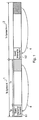
- Figure 1 A diagram representing the time domain OFDM symbols is shown in Figure 1.
- each OFDM symbol 1, 2 has a useful part of the symbol during which the data is transmitted. This part of the symbol has duration of T u seconds and has N u samples.
- a guard interval G.1, G.2 of duration T g seconds separates the current symbol from the previous one.
- the guard interval has N g samples.
- the guard interval G.1, G.2 therefore precedes the useful part of the symbol and is formed, as indicated by an arrow 4, by replicating the samples in the last T g seconds of the useful part of the symbol.
- the receiver In order to recover the data within the OFDM symbols, the receiver must detect the data bearing signal samples from within the set of received signal samples corresponding to each OFDM symbol.
- a receiver for detecting and recovering data from a OFDM symbol is shown in Figure 2.
- an analogue to digital converter 100 is arranged to receive an intermediate frequency (IF) signal representing the detected radio signal on which the OFDM symbol has been modulated.
- the receiver also includes down conversion means and detection means in order to convert the radio frequency signal into an intermediate frequency signal, which is fed to the analogue to digital converter 100 via an input 102.
- the receiver may also include radio frequency receiving and down converting means which are not shown in Figure 2.
- the received signal is processed by an intermediate frequency to base band conversion means 104 before being processed by a re-sampling and carrier offset correction processor 106.
- the radio frequency signal may be directly converted to base-band.
- the intermediate frequency input to the analogue to digital converter 100 is zero Hertz and so there is no need for the intermediate frequency to base band conversion means 104.
- the re-sampling and carrier offset correction processor 106 is arranged to track in the frequency domain the K carriers of the OFDM modulation.
- the base band received signal samples are then fed to a Fast Fourier transform processor 108 which serves to convert the time domain received signal samples into the frequency domain.
- the data is then recovered from the frequency domain signal samples by a post FFT processor 110.
- the data is then fed to a forward error correction processor 112 which operates to decode the error correction encoded data to produce the recovered data at an output 114.
- the receiver locates an FFT window time from which the data bearing signal samples are processed by the FFT processor 108.
- the FFT window position is adjusted in order that the window includes the maximum energy representative of the data bearing signal samples.
- an FFT symbol timing recovery processor 116 is arranged to generate a signal indicative of a symbol sync time which is fed to the FFT processor 108 via a connecting channel 118.
- the FFT symbol timing recovery processor 116 is arranged to detect the Symbol Sync Time (SST) from the received set of signal samples which represent each OFDM symbol. These are received from the re-sampling and carrier offset correction processor 106 via a connecting channel 120.
- SST Symbol Sync Time
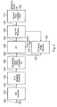
- the FFT symbol-timing recovery processor 116 and the post-FFT processor 110 are shown in more detail in Figure 3.
- the FFT symbol-timing recovery processor 116 and the post-FFT processor 110 operate to provide a symbol timing recovery process, which is described in [1].
- the time domain samples representing the OFDM symbol are received by the FFT processor 108.
- the FFT processor 108 converts the time domain samples into the frequency domain.
- the frequency domain samples are then fed to the post-FFT processor 110.
- the time domain samples are also fed to a symbol timing recovery processor 116, and in particular to a symbol time adjustment estimator 220.
- the symbol time adjustment estimator 220 includes a filter matched to the samples of the guard interval.
- the matched filter is excited by the OFDM symbol to produce an output signal from which the SST is calculated, assisted by a signal provided by the pilot assisted symbol time estimator 230.
- the output of the matched filter includes prominent pulses representing the discrete propagation paths existing on the channel.
- the SST is computed from the relative time of arrival of the earliest arriving prominent path.
- the difference between the relative times of arrival of the earliest and latest arriving paths is also calculated. This difference is an estimate of the channel response delay spread that is sent to the channel corrector 250 the operation of which is the main subject of this application.
- each OFDM symbol or row of the matrix of Figure 4 is converted into the time domain using an inverse Fourier transform.
- Such distortions may include:
- a pilot-assisted channel estimator 240 is arranged to use the combined known transmissions at the pilot cells to estimate and reduce the effects of H(n,k) within a given budget of time, complexity, power consumption and cost.
- the effects are estimated in both time and frequency dimension by interpolation of the samples of the CTF derived from the pilot cells.
- distortion from frequency selective fading and noise can be estimated by calculations on the pilot cells of individual symbols along the frequency dimension.
- Distortions from Doppler shifts and time variation of the channel can be calculated across symbols along the time dimension. It is possible to combine both these calculations in a kind of two-dimensional channel estimation process but the computations required would be rather intensive [3]. Practical demodulators therefore carry out these calculations in sequence, often estimating the time dimension distortions first, followed by those in the frequency dimension.
- the above equation is used at the pilot cells to estimate the sample of the CTF at the given cell.
- the OFDM symbol includes a number of pilot cells, the positions, expected amplitudes and phases of which are known to the receiver.
- the post-FFT processor 110 is able to extract these received pilot cells from the frequency domain samples output from the FFT processor 108.
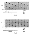
- Figure 4 schematically illustrates a multi-carrier signal matrix representing the transmission of data using OFDM.
- the matrix is composed of symbols of duration T u seconds each symbol having bandwidth of N u /T u where N u is the number of OFDM sub-carriers or cells in the signal.
- N u is 1705 for the so-called 2K system, 3409 for a 4K system and 6817 for the 8K system.
- the values for T u are respectively 224us, 448us and 896us.
- the rows of the matrix represent the individual symbols in time whilst the columns show the sub-carriers (in the frequency domain) of the given symbol.
- Each cell in the signal matrix of Figure 4 is sent as a QAM symbol with varying amplitudes and phases dependent on the data at the transmitter.
- the expected amplitudes and phases of the pilot symbol cells are known both to the transmitter and the receiver.
- the amplitude and phase of a sub-carrier at the position of the continuous pilot is known for all symbols.
- the position of the scattered pilots within each symbol vary in accordance with a predetermined pattern.
- There may be other sub-carriers such as those that convey the transmission parameters signalling (TPS) whose phases and amplitudes can be readily derived at the receiver.
- TPS transmission parameters signalling
- the other cells are modulated with QAM symbols that carry the actual payload of the transmission system in their phases and amplitudes. It is the extraction of this payload that is the job of the demodulator.
- the pilot assisted channel estimator 240 operates on the frequency domain carriers from the FFT block 108. From amongst all the carriers, the pilot carriers are identified and extracted. There are only a limited number of pilot carriers per OFDM symbol, which in the example of DVB-T are spaced nominally every twelve carriers.
- the channel estimator computes the value of the CTF at each pilot cell by dividing the complex value of each received pilot by its known or expected complex value. The result of this for a given OFDM symbol is in effect a twelve-fold decimated version of the CTF designated as H 12 (k).
- the pilot cells are distributed between successive OFDM symbols in a manner that allows further reduction of this sample spacing by use of time dimension processing such as described in [2].
- This additional time-dimension processing has the effect of interpolating the CTF estimates over a number of successive OFDM symbols in the time dimension.
- Such time dimension processing is not the subject of the current application but in the example of DVB-T such techniques can be applied to successive estimates of H 12 (k) to produce a 3-fold decimation of the CTF estimate H 3 (k).
- the channel estimator then interpolates the CTF in the frequency dimension by a factor of three so that a CTF estimate is provided for every carrier including the data-bearing carriers.
- Figure 5 schematically illustrates the matrix after time dimension processing to obtain H 3 (k) .
- the CTF is not known yet and so is set to zero.
- the CTF samples at these cells will be calculated subsequently by the frequency dimension processing.
- the frequency dimension processing to compute the full CTF H(k) is a filtering operation to complete the 3-fold interpolation along the frequency dimension of H 3 (k) .
- these CTF estimates are sent to the Channel Corrector block 250 where they are used to equalise the effect of the channel on the data.
- Noise can be introduced into the interpolated signal not only by the choice of F c relative to B and F 1 but also inadequate stop-band attenuation.
- stop-band attenuation is largely a function of filter order, adequate attenuation can be assured by choice of appropriate order for the interpolation filter.
- the signal to be filtered by the interpolation filter is composed of frequency domain samples. Accordingly, the signal to be windowed by the interpolation filter's transfer function is a time domain signal - the channel impulse response.
- the bandwidth of the filter can therefore be expressed as the duration of the window formed from the frequency response of the filter.
- the sampling rate F 1 of H 3 (k) is a third of the ultimate sampling rate of the full CTF H(k) , this means that the estimated H(k) is only resolvable to one third of the output sampling rate of 3F 1 .
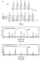
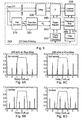
- Figures 7A and 7B schematically illustrate the frequency interpolation filter's transfer function G(k) as a window over the channel impulse response (CIR) as explained above.
- the horizontal axes in Figures 7A and 7B are therefore in units of T u / 6 seconds.
- the CIR is composed of two paths.
- Figure 7A the main path at zero delay is followed by a -2dB echo T u / 11 seconds later whilst in Figure 7B there is a -2dB path at zero relative delay followed by the main path 2T u /11 seconds later.
- the filter frequency response window also has a maximum duration (bandwidth) of T u / 3 seconds implying a maximum cut-off frequency of ⁇ T u /6 seconds for the filter.
- the CIR has a delay spread of 2T u / 11 seconds that is larger than T u /6 seconds. This results in the main path of the target CIR replica lying just beyond the -3dB point ( T u /6 seconds) of the frequency response window whilst also pulling in the main path component of the CIR replica that starts at - 2T u /6 seconds.
- T u /6 seconds the main path component of the CIR replica that starts at - 2T u /6 seconds.
- the tracker includes a time domain based mode which uses a guard interval adapted matched filter (MF) to estimate and then track the CIR by finding the TOA of all paths that lie within Tg seconds of the main path where T g is the duration of the guard interval in use.
- MF guard interval adapted matched filter
- this range was extended to cover all propagation paths that lie within ⁇ 7T u /24 seconds of the main path.
- Figure 7B illustrates the problem of noise arising from frequency interpolation of H 3 (k) when the CIR delay spread is longer than T u /6 seconds.
- the last impulse in the CIR would lie just beyond the -3dB point of the filter frequency response window whilst on the other hand, the last path of the CIR replica starting at -2T u /6 seconds will fall under the window contributing noise.
- the CIR delay spread it is possible according to the present technique to shift the required CIR replica in a manner as to centre it underneath the window thereby avoiding both degradations.
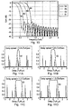
- Figures 8A to 8D schematically illustrate the frequency interpolation filter's transfer function G (k) as a window over the channel impulse response (CIR) as explained above.
- Figures 8A and 8B illustrate a so-called “pre-echo” CIR in which the main path follows a -2dB path that arrived 2T u / 11 seconds previously.
- Figures 8C and 8D illustrate a so-called "post-echo” CIR in which the main path is followed 2T u /11 seconds later by a -2dB echo.
- Figures 8A and 8C illustrate the windowing of the CIR if it were un-centred whilst Figures 8B and 8D illustrate the centred CIR windowing for each CIR, respectively.
- the wider the duration (bandwidth) of the interpolation filter frequency response window the more of this noise is incorporated into the frequency interpolation. Therefore, reducing the window duration (interpolation filter bandwidth) from its maximum T u / 3 seconds, would also reduce the amount of backstop noise in the interpolation.
- the interpolation filter's frequency response When seen as a window over the CIR, the interpolation filter's frequency response only has to be as wide as the CIR delay spread of the channel. With the delay spread provided by the symbol tracker summarised above, it is thus possible to dimension the bandwidth of the frequency interpolation filter accordingly. It is possible to re-compute the coefficients of such a filter every time the CIR delay spread changes by changing for example a Kaiser factor in the window design method for FIR filters [9]. Another way of adapting the frequency interpolation filter's cut-off frequency to the CIR delay spread is to switch-in different pre-designed filters of varying cut-off frequencies dependent on the current value of the CIR delay spread.
- Figure 9 schematically illustrates an example of a pilot assisted channel estimator 240 according to the present technique.
- the pilot assisted channel estimator 240 receives the frequency domain symbol samples from the FFT.
- the pilot carriers are extracted from the received symbol by a Pilot Extractor 310 and used to form an estimate of the channel.
- the estimate of the channel transfer function H 12 (k) provides a discretely sub-sampled Channel Transfer Function (CTF) in accordance with a sampling rate of one twelfth that of the symbol samples from the FFT.
- CTF Channel Transfer Function
- Interpolation of the CTF in the time dimension is then performed by a time axis interpolator 320, by utilising CTF estimates from successive symbols.
- the time axis interpolation provides a facility of increasing the sampling rate of the CTF to one in three. Accordingly, the time axis interpolator 320 forms CTF samples H 3 (k), which are received by a phase adjuster 340.
- the phase adjuster 340 spins H 3 (k) to center the CIR under the frequency interpolator filter window prior to frequency interpolation filtering by the frequency axis interpolator 360. This spinning is achieved by using the CIR delay spread ⁇ for the current channel conditions provided by the symbol time adjustment estimator 220 to generate a phase spin ⁇ /2 provided by the phase offset calculator 350.
- the phase offset calculator 350 includes a look up table providing sine and cosine coefficients that represent the required phase spin ⁇ /2according to Euler's equation.
- the frequency axis interpolator 360 then forms a centered interpolated full-band version of the CTF by interpolating in the frequency dimension the phase adjusted sub-sampled version of the channel transfer function.
- the Channel Estimator is provided with a filter selector 370 which receives the CIR delay spread ⁇ from the symbol time adjustment estimator and which selects a predetermined interpolation filter of an appropriate bandwidth for use by the Frequency Axis Interpolator 360.
- the noise degradations identified above are thus inhibited by centering the CIR and using a frequency interpolation filter appropriate to the delay spread of the channel.
- the channel corrector 250 then applies the CTF estimate to correct for the effects of the channel impulse response on the received symbol.
- the Delay block 330 is used to store the data carriers whilst channel estimation takes place.
- the phase adjuster 380 applies the same phase spin to the data-bearing carriers as is applied to H 3 (k).
- Figure 10 shows the frequency characteristics of four example interpolation filters, having varying cut-off frequencies, that can be selected by a filter controller 370 for use by the Frequency Axis Interpolator 360.
- FIGs 11A to 11D illustrates the window function of the four filters illustrated in Figure 10, each filter being selected according to the CIR delay spread. Each CIR has undergone the appropriate phase spin whose result is to centre the CIR under its particular interpolation filter window. Notice the reduced level of backstop noise falling under the filter of narrowest bandwidth ( Figure 11A) as compared with filters of greater bandwidth ( Figures 11B to 11D).
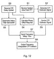
- Figure 12 schematically illustrates a method of performing frequency interpolation of a channel impulse response (CIR) estimate signal including pilots signals.
- CIR channel impulse response
- symbol data including pilot signals is received from an FFT processor.
- pilot signals are extracted from the symbol data and used to generate a CTF estimate signal.
- an indication of the channel impulse response (CIR) delay spread is received at the frequency interpolation apparatus.
- the received CIR delay spread is used to calculate a phase offset required to reduce energy from aliases which may be present in the CTF estimate signal while retaining desired signal components within a pass band window of a frequency interpolation filter.
- the CTF estimate signal is shifted in accordance with the phase offset calculated in the step S4.
- the CIR delay spread received in step S3 is used to determine a suitable bandwidth for the frequency interpolation filter.
- a frequency interpolation filter having a bandwidth as determined in step S6 is applied to the shifted CTF estimate signal generated in step S5. This results in a frequency interpolated CTF estimate signal, which is output at a step S8.
- pilot should be interpreted broadly as meaning any signal or data symbols, which are transmitted with the data to be communicated, and which are known to the receiver.
- embodiments of the present invention may use either frequency interpolation or time interpolation or both, one of the time or frequency dimension channel response interpolation techniques being used without the other. For example, if an OFDM signal includes only continuous pilots then time dimension interpolation may not be required.
Applications Claiming Priority (2)
| Application Number | Priority Date | Filing Date | Title |
|---|---|---|---|
| GB0406875 | 2004-03-26 | ||
| GB0406875A GB2412551A (en) | 2004-03-26 | 2004-03-26 | Receiver |
Publications (3)
| Publication Number | Publication Date |
|---|---|
| EP1580951A2 true EP1580951A2 (fr) | 2005-09-28 |
| EP1580951A3 EP1580951A3 (fr) | 2006-10-04 |
| EP1580951B1 EP1580951B1 (fr) | 2010-01-20 |
Family
ID=32188790
Family Applications (1)
| Application Number | Title | Priority Date | Filing Date |
|---|---|---|---|
| EP05251027A Not-in-force EP1580951B1 (fr) | 2004-03-26 | 2005-02-23 | Récepteur |
Country Status (6)
| Country | Link |
|---|---|
| US (1) | US7440506B2 (fr) |
| EP (1) | EP1580951B1 (fr) |
| JP (1) | JP2005312027A (fr) |
| AT (1) | ATE456233T1 (fr) |
| DE (1) | DE602005018985D1 (fr) |
| GB (1) | GB2412551A (fr) |
Cited By (9)
| Publication number | Priority date | Publication date | Assignee | Title |
|---|---|---|---|---|
| EP1814274A1 (fr) * | 2006-01-30 | 2007-08-01 | Sony Corporation | Démodulateur, récepteur et procédé OFDM |
| GB2441887A (en) * | 2006-09-13 | 2008-03-19 | Sunplus Technology Co Ltd | OFDM frequency domain channel estimator using peaks of time interpolated pilot estimate and symbol feedback to determine relative time corrections |
| WO2008086063A2 (fr) * | 2007-01-05 | 2008-07-17 | Qualcomm Incorporated | Station hautes performances |
| EP1936901A3 (fr) * | 2006-12-21 | 2008-07-30 | Samsung Electronics Co., Ltd. | Appareil et procédé d'estimation de canal dans un système de communication à accès sans fil à large bande |
| WO2009032385A1 (fr) * | 2007-09-05 | 2009-03-12 | Newport Media, Inc. | Interpolation adaptative de domaine temporel pour symboles pilotes dispersés ofdm |
| EP2077649A1 (fr) * | 2008-01-04 | 2009-07-08 | Ali Corporation | Procédé d'évaluation de canal et estimateur de canal l'utilisant |
| GB2470767A (en) * | 2009-06-03 | 2010-12-08 | Sony Corp | OFDM channel estimation using pilots and a filter cascade |
| EP2157753A3 (fr) * | 2008-08-21 | 2010-12-15 | Sony Corporation | Réglage d'interpolation pour l'estimation de canal |
| CN103595678A (zh) * | 2012-08-08 | 2014-02-19 | 北京泰美世纪科技有限公司 | 数字音频广播信号的离散导频信号生成方法和装置 |
Families Citing this family (61)
| Publication number | Priority date | Publication date | Assignee | Title |
|---|---|---|---|---|
| KR100770924B1 (ko) * | 2005-02-04 | 2007-10-26 | 삼성전자주식회사 | 무선 통신 시스템에서 주파수 오차 보상 장치 및 방법 |
| WO2006098011A1 (fr) * | 2005-03-16 | 2006-09-21 | Fujitsu Limited | Dispositif de communication radio dans un systeme a entrees multiples et procede d'estimation et de separation de voies |
| US7848463B2 (en) * | 2005-04-07 | 2010-12-07 | Qualcomm Incorporated | Adaptive time-filtering for channel estimation in OFDM system |
| TW200705913A (en) * | 2005-05-27 | 2007-02-01 | Mediaphy Corp | Adaptive interpolator for channel estimation |
| JP2009502077A (ja) * | 2005-07-20 | 2009-01-22 | エヌエックスピー ビー ヴィ | Dvb‐h信号受信方法及びdvb‐h受信機 |
| JP3841819B1 (ja) * | 2005-11-08 | 2006-11-08 | 三菱電機株式会社 | 直交周波数分割多重信号の受信装置および受信方法 |
| JP4264550B2 (ja) * | 2005-11-15 | 2009-05-20 | ソニー株式会社 | 受信装置並びにチャネル推定装置 |
| FR2895605A1 (fr) * | 2005-12-22 | 2007-06-29 | Thomson Licensing Sas | Procede de reception d'un signal a porteuses multiples, procede d'emission, recepteur et emetteur correspondants |
| CN101371251A (zh) * | 2005-12-28 | 2009-02-18 | 意大利电信股份公司 | 通信系统中用于信道估计的插值方法及相关设备 |
| IL173069A0 (en) * | 2006-01-10 | 2006-06-11 | Zion Hadad Dr | Cellular system and method |
| CN101406016A (zh) * | 2006-03-17 | 2009-04-08 | 松下电器产业株式会社 | 无线通信基站装置及导频配置方法 |
| US8077784B2 (en) * | 2006-05-24 | 2011-12-13 | Panasonic Corporation | OFDM demodulation device |
| JP4664234B2 (ja) * | 2006-05-24 | 2011-04-06 | 富士通セミコンダクター株式会社 | Ofdm受信機 |
| US7580468B2 (en) * | 2006-07-28 | 2009-08-25 | Samsung Electronics Co., Ltd. | Synchronization circuits, orthogonal frequency division multiplexing (OFDM) receivers, and related methods and computer program products |
| US8290031B1 (en) * | 2006-08-14 | 2012-10-16 | The Board Of Trustees Of The Leland Stanford Junior University | Arrangements and methods for providing compensation for non-idealities of components in communications systems |
| US7940849B1 (en) * | 2006-08-25 | 2011-05-10 | Marvell International Ltd. | Method and apparatus for estimation of carrier frequency offset and/or sampling frequency offset |
| JP4747064B2 (ja) * | 2006-09-29 | 2011-08-10 | 富士通株式会社 | プリアンブル検出装置および無線受信機 |
| US7830994B2 (en) * | 2006-10-18 | 2010-11-09 | Analog Devices, Inc. | Channel estimation system and method |
| US7961806B2 (en) * | 2007-01-23 | 2011-06-14 | Mediatek Inc. | Power adaptive channel estimation for a multi-path receiving |
| EP2109974B1 (fr) * | 2007-01-29 | 2019-10-16 | III Holdings 6, LLC | Procédé d'estimation de la voie de transmission d'un signal à porteuses multiples à sélection temporelle ou interpolation de domaine de fréquence selon le décalage de fréquence pilote en continu |
| DE602007014174D1 (de) * | 2007-02-05 | 2011-06-09 | Sequans Comm | Verfahren und Vorrichtung zur Zeitsynchronisation und Scanning von Nachbarzellen für zelluläre OFDM-Systeme |
| WO2008096322A1 (fr) * | 2007-02-09 | 2008-08-14 | Nxp B.V. | Procédé de synchronisation de systèmes multiporteuses et système multiporteuse |
| US9391813B2 (en) * | 2007-02-16 | 2016-07-12 | Maxlinear, Inc. | Long echo detection and channel estimation for OFDM systems |
| WO2008129825A1 (fr) | 2007-03-27 | 2008-10-30 | Panasonic Corporation | Dispositif de réception par modulation par répartition orthogonale de la fréquence (ofdm), procédé de réception ofdm, circuit de réception ofdm, circuit intégré et programme |
| US8000399B2 (en) * | 2007-06-14 | 2011-08-16 | Bhaskar Patel | Adaptive joint channel estimation and data demodulation for OFDM systems |
| JP2009044364A (ja) * | 2007-08-08 | 2009-02-26 | Hitachi Kokusai Electric Inc | Ofdm受信装置 |
| JP5098553B2 (ja) * | 2007-10-10 | 2012-12-12 | 富士通セミコンダクター株式会社 | Ofdm受信装置およびofdm受信方法 |
| CN101843061B (zh) | 2007-11-01 | 2012-12-19 | Nxp股份有限公司 | 区分实际回波峰与混叠回波峰的方法 |
| EP2071784B1 (fr) * | 2007-12-10 | 2013-05-22 | TELEFONAKTIEBOLAGET LM ERICSSON (publ) | Procédé et appareil d'évaluation de dispersion de délai |
| EP2071787B1 (fr) * | 2007-12-10 | 2013-03-13 | TELEFONAKTIEBOLAGET LM ERICSSON (publ) | Procédé et appareil de positionnement d'une fenêtre FFT dans un récepteur OFDM |
| KR100900640B1 (ko) | 2007-12-27 | 2009-06-02 | 삼성전기주식회사 | 디지털 방송 수신 시스템의 ofdm 수신 장치 |
| US20090185630A1 (en) * | 2008-01-23 | 2009-07-23 | Mediatek Inc. | Method and apparatus for estimating the channel impulse response of multi-carrier communicating systems |
| JP4600559B2 (ja) | 2008-02-29 | 2010-12-15 | ソニー株式会社 | 受信装置、受信方法、およびプログラム |
| US8340220B2 (en) * | 2008-04-11 | 2012-12-25 | Panasonic Corporation | Receiver, integrated circuit, digital television receiver, reception method, and reception program |
| JP5169423B2 (ja) * | 2008-04-16 | 2013-03-27 | 富士通株式会社 | 移動局装置及び伝送路推定方法 |
| JP2009278448A (ja) * | 2008-05-15 | 2009-11-26 | Fujitsu Microelectronics Ltd | Ofdm受信機およびofdm受信方法 |
| GB2460417B (en) | 2008-05-28 | 2011-04-06 | Mirics Semiconductor Ltd | Broadcast receiver system |
| GB2460418B (en) * | 2008-05-28 | 2010-04-14 | Mirics Semiconductor Ltd | Broadcast receiver system |
| US8174958B2 (en) * | 2008-08-01 | 2012-05-08 | Broadcom Corporation | Method and system for a reference signal (RS) timing loop for OFDM symbol synchronization and tracking |
| US8559296B2 (en) * | 2008-08-01 | 2013-10-15 | Broadcom Corporation | Method and system for an OFDM joint timing and frequency tracking system |
| JP4623180B2 (ja) * | 2008-09-19 | 2011-02-02 | ソニー株式会社 | 受信装置、受信方法、およびプログラム |
| JP2010114883A (ja) * | 2008-10-10 | 2010-05-20 | Hitachi Kokusai Electric Inc | Ofdm受信装置および中継装置 |
| CN101741778B (zh) * | 2008-11-11 | 2013-06-05 | 中兴通讯股份有限公司 | 一种数据子载波上的信道估计方法 |
| WO2010081896A2 (fr) * | 2009-01-16 | 2010-07-22 | Abilis Systems Sarl | Évaluation interpolée des canaux pour systèmes ofdm mobiles |
| KR100978672B1 (ko) | 2009-01-19 | 2010-08-30 | 삼성전기주식회사 | Ofdm 채널 매트릭스 생성 장치 및 그 방법 |
| US8312346B2 (en) | 2009-05-01 | 2012-11-13 | Mirics Semiconductor Limited | Systems and methods for communications |
| GB2470768A (en) * | 2009-06-03 | 2010-12-08 | Sony Corp | Receiver for OFDM symbols in a MISO system with Alamouti-type encoding |
| GB2470753A (en) | 2009-06-03 | 2010-12-08 | Sony Corp | Receiver and method for processing pilot data in an ofdm system |
| US8325790B2 (en) * | 2009-08-03 | 2012-12-04 | Analog Devices, Inc. | Equalization for OFDM communication |
| US20130039303A1 (en) | 2010-02-11 | 2013-02-14 | Sony Corporation | Mapping apparatus and method for transmission of data in a multi-carrier broadcast system |
| JP5577884B2 (ja) * | 2010-06-28 | 2014-08-27 | ソニー株式会社 | 受信装置、及び、受信方法、並びに、受信システム |
| US9124396B2 (en) * | 2011-07-28 | 2015-09-01 | Allen LeRoy Limberg | COFDM digital television receivers for iterative-diversity reception |
| US8718210B2 (en) | 2011-09-20 | 2014-05-06 | Qualcomm Incorporated | Channel impulse response estimation for wireless receiver |
| US9197400B1 (en) | 2012-05-21 | 2015-11-24 | Marvell International Ltd. | Method and apparatus for joint estimation of carrier frequency offset and sampling frequency offset |
| US9350587B1 (en) | 2012-11-30 | 2016-05-24 | Marvell International Ltd. | System and method for timing error estimation |
| US9008203B2 (en) | 2013-03-13 | 2015-04-14 | Sony Corporation | Transmitters, receivers and methods of transmitting and receiving |
| US20140294124A1 (en) * | 2013-03-28 | 2014-10-02 | Sony Corporation | Transmitter and method of transmitting and receiver and method of detecting ofdm signals |
| CN105284068B (zh) | 2013-06-05 | 2019-08-27 | 索尼公司 | 用于传输有效载荷数据和紧急信息的传输器和传输方法 |
| GB2515801A (en) | 2013-07-04 | 2015-01-07 | Sony Corp | Transmitter and receiver and methods of transmitting and receiving |
| EP3900284B1 (fr) * | 2018-12-17 | 2023-11-08 | U-blox AG | Estimation d'une ou plusieurs caractéristiques d'un canal de communication |
| CN111835314B (zh) * | 2020-08-06 | 2023-06-13 | 四川安迪科技实业有限公司 | 用于1~2倍间任意倍数抽取的抗干扰抽取器及其设计方法 |
Citations (5)
| Publication number | Priority date | Publication date | Assignee | Title |
|---|---|---|---|---|
| EP0998068A1 (fr) * | 1998-02-20 | 2000-05-03 | Sony Corporation | Procede et appareil de reception de signaux et support associe |
| US20030012308A1 (en) * | 2001-06-13 | 2003-01-16 | Sampath Hemanth T. | Adaptive channel estimation for wireless systems |
| US6614852B1 (en) * | 1999-02-26 | 2003-09-02 | Thomson-Csf | System for the estimation of the complex gain of a transmission channel |
| WO2004100413A1 (fr) * | 2003-05-12 | 2004-11-18 | Mitsubishi Denki Kabushiki Kaisha | Dispositif de demodulation et procede de demodulation |
| US20050105647A1 (en) * | 2003-11-13 | 2005-05-19 | Leif Wilhelmsson | Channel estimation by adaptive interpolation |
Family Cites Families (9)
| Publication number | Priority date | Publication date | Assignee | Title |
|---|---|---|---|---|
| JP2772286B2 (ja) * | 1996-08-30 | 1998-07-02 | 株式会社次世代デジタルテレビジョン放送システム研究所 | 直交周波数分割多重信号復調装置 |
| IT1288778B1 (it) * | 1996-10-25 | 1998-09-24 | Rai Radiotelevisione Italiana | Procedimento e apparato di ricezione di segnali numerici in multiplex codificato e divisione di frequenze. |
| JP2001308760A (ja) * | 2000-04-27 | 2001-11-02 | Nec Eng Ltd | 受信装置 |
| SG99310A1 (en) * | 2000-06-16 | 2003-10-27 | Oki Techno Ct Singapore Pte | Methods and apparatus for reducing signal degradation |
| JP4460738B2 (ja) * | 2000-08-21 | 2010-05-12 | 株式会社ケンウッド | 直交周波数分割多重信号受信装置及び直交周波数分割多重信号受信方法 |
| JP2002261729A (ja) * | 2001-03-06 | 2002-09-13 | Hitachi Ltd | Ofdm受信装置 |
| US20030063678A1 (en) * | 2001-08-21 | 2003-04-03 | Crawford James A. | OFDM pilot tone tracking to reduce performance loss due to frequency pulling and pushing |
| US8553822B2 (en) * | 2004-01-28 | 2013-10-08 | Qualcomm Incorporated | Time filtering for excess delay mitigation in OFDM systems |
| GB2412552A (en) * | 2004-03-26 | 2005-09-28 | Sony Uk Ltd | Receiver |
-
2004
- 2004-03-26 GB GB0406875A patent/GB2412551A/en not_active Withdrawn
-
2005
- 2005-02-23 DE DE602005018985T patent/DE602005018985D1/de active Active
- 2005-02-23 AT AT05251027T patent/ATE456233T1/de not_active IP Right Cessation
- 2005-02-23 EP EP05251027A patent/EP1580951B1/fr not_active Not-in-force
- 2005-03-24 US US11/088,310 patent/US7440506B2/en active Active
- 2005-03-28 JP JP2005092967A patent/JP2005312027A/ja active Pending
Patent Citations (5)
| Publication number | Priority date | Publication date | Assignee | Title |
|---|---|---|---|---|
| EP0998068A1 (fr) * | 1998-02-20 | 2000-05-03 | Sony Corporation | Procede et appareil de reception de signaux et support associe |
| US6614852B1 (en) * | 1999-02-26 | 2003-09-02 | Thomson-Csf | System for the estimation of the complex gain of a transmission channel |
| US20030012308A1 (en) * | 2001-06-13 | 2003-01-16 | Sampath Hemanth T. | Adaptive channel estimation for wireless systems |
| WO2004100413A1 (fr) * | 2003-05-12 | 2004-11-18 | Mitsubishi Denki Kabushiki Kaisha | Dispositif de demodulation et procede de demodulation |
| US20050105647A1 (en) * | 2003-11-13 | 2005-05-19 | Leif Wilhelmsson | Channel estimation by adaptive interpolation |
Non-Patent Citations (3)
| Title |
|---|
| FRIEDER S, SPEIDEL J: "An Adaptive Two-Dimensional Channel Estimator for Wireless OFDM with Application to Mobile DVB-T" IEEE TRANSACTIONS ON BROADCASTING, vol. 46, no. 2, June 2000 (2000-06), XP011006127 IEEE, PISCATAWAY, NJ, US ISSN: 0018-9316 * |
| MIGNONE V, MORELLO A: "CD3-OFDM: A Novel Demodulation Scheme for Fixed and Mobile Receivers" IEEE TRANSACTIONS ON COMMUNICATIONS, vol. 44, no. 9, September 1996 (1996-09), XP011008784 IEEE, PISCATAWAY, NJ, US ISSN: 0090-6778 * |
| RAMASUBRAMANIAN K, BAUM K: "An OFDM timing recovery scheme with inherent delay-spread estimation" IEEE GLOBAL TELECOMMUNICATIONS CONFERENCE (GLOBECOM'01), vol. 5 of 6, 25 November 2001 (2001-11-25), pages 3111-3115, XP010747382 IEEE, NEW YORK, NY, US ISBN: 0-7803-7206-9 * |
Cited By (19)
| Publication number | Priority date | Publication date | Assignee | Title |
|---|---|---|---|---|
| EP1814274A1 (fr) * | 2006-01-30 | 2007-08-01 | Sony Corporation | Démodulateur, récepteur et procédé OFDM |
| US7664189B2 (en) | 2006-01-30 | 2010-02-16 | Sony Corporation | OFDM demodulator, receiver, and method |
| GB2441887B (en) * | 2006-09-13 | 2009-02-11 | Sunplus Technology Co Ltd | Channel estimation apparatus with the optimal search and method thereof |
| GB2441887A (en) * | 2006-09-13 | 2008-03-19 | Sunplus Technology Co Ltd | OFDM frequency domain channel estimator using peaks of time interpolated pilot estimate and symbol feedback to determine relative time corrections |
| DE102007043645A1 (de) | 2006-09-13 | 2008-07-10 | Sunplus Technology Co., Ltd. | Vorrichtung für das Schätzen von Kanälen mit der optimalen Suche und Verfahren derselben |
| US7936844B2 (en) | 2006-09-13 | 2011-05-03 | Sunplus Technology Co., Ltd. | Channel estimation apparatus with the optimal search and method thereof |
| EP1936901A3 (fr) * | 2006-12-21 | 2008-07-30 | Samsung Electronics Co., Ltd. | Appareil et procédé d'estimation de canal dans un système de communication à accès sans fil à large bande |
| US7936848B2 (en) | 2006-12-21 | 2011-05-03 | Samsung Electronics Co., Ltd. | Apparatus and method for estimating channel in broadband wireless access (BWA) communication system |
| WO2008086063A3 (fr) * | 2007-01-05 | 2008-11-20 | Qualcomm Inc | Station hautes performances |
| WO2008086063A2 (fr) * | 2007-01-05 | 2008-07-17 | Qualcomm Incorporated | Station hautes performances |
| US9253009B2 (en) | 2007-01-05 | 2016-02-02 | Qualcomm Incorporated | High performance station |
| WO2009032385A1 (fr) * | 2007-09-05 | 2009-03-12 | Newport Media, Inc. | Interpolation adaptative de domaine temporel pour symboles pilotes dispersés ofdm |
| EP2077649A1 (fr) * | 2008-01-04 | 2009-07-08 | Ali Corporation | Procédé d'évaluation de canal et estimateur de canal l'utilisant |
| EP2157753A3 (fr) * | 2008-08-21 | 2010-12-15 | Sony Corporation | Réglage d'interpolation pour l'estimation de canal |
| US8175204B2 (en) | 2008-08-21 | 2012-05-08 | Sony Corporation | Receiving device, signal processing method, and program |
| CN101656703B (zh) * | 2008-08-21 | 2012-10-03 | 索尼株式会社 | 接收设备、信号处理方法和程序 |
| GB2470767A (en) * | 2009-06-03 | 2010-12-08 | Sony Corp | OFDM channel estimation using pilots and a filter cascade |
| CN103595678A (zh) * | 2012-08-08 | 2014-02-19 | 北京泰美世纪科技有限公司 | 数字音频广播信号的离散导频信号生成方法和装置 |
| CN103595678B (zh) * | 2012-08-08 | 2017-07-25 | 北京泰美世纪科技有限公司 | 数字音频广播信号的离散导频信号生成方法和装置 |
Also Published As
| Publication number | Publication date |
|---|---|
| EP1580951B1 (fr) | 2010-01-20 |
| JP2005312027A (ja) | 2005-11-04 |
| ATE456233T1 (de) | 2010-02-15 |
| DE602005018985D1 (de) | 2010-03-11 |
| GB2412551A (en) | 2005-09-28 |
| EP1580951A3 (fr) | 2006-10-04 |
| US20050213680A1 (en) | 2005-09-29 |
| US7440506B2 (en) | 2008-10-21 |
| GB0406875D0 (en) | 2004-04-28 |
Similar Documents
| Publication | Publication Date | Title |
|---|---|---|
| EP1580951B1 (fr) | Récepteur | |
| US7388922B2 (en) | Receiver | |
| JP4159030B2 (ja) | Ofdmを用いる無線ネットワーク用のタイミング同期方法 | |
| US8437426B2 (en) | Receiving apparatus, receiving method, and program | |
| KR20170084081A (ko) | 프리앰블 기반의 ofdm 미세 주파수 오프셋 추정 | |
| US20170026219A1 (en) | Receiver and method of receiving | |
| EP1416693A2 (fr) | Récupération de l'horloge de symboles dans un récepteur multiporteur | |
| EP2290893A1 (fr) | Synchronisation de fréquence dans un recepteur OFDM par utilisation d'une transformée de Fourrier glissante | |
| JPWO2008126356A1 (ja) | Ofdm受信装置及びofdm受信方法 | |
| EP2204958B1 (fr) | Procédé et système pour la récupération de la temporisation du symbole ofdm | |
| US20170026221A1 (en) | Receiver and method of receiving | |
| KR101468514B1 (ko) | 통신 시스템에서의 잔류 주파수 에러를 추정하는 방법 및 장치 | |
| KR100213100B1 (ko) | Ofdm 전송 신호의 주파수 오류 정정기와 그 방법 | |
| US8483323B2 (en) | Methods and apparatuses for channel estimation of OFDM systems to combat multipath fading | |
| EP1821407B1 (fr) | Système d'estimation de canal d'OFDM | |
| WO2007096663A2 (fr) | Systemes mrof d'estimation de canal | |
| JP3993441B2 (ja) | Ofdm信号受信装置 | |
| EP1387544B1 (fr) | Synchronisation dans des récepteurs multiporteuses | |
| WO2011086609A1 (fr) | Appareil de réception de diffusion numérique et procédé de génération de profil de retard | |
| JP2002344411A (ja) | Ofdm復調装置及び方法 | |
| JP5274210B2 (ja) | Ofdm復調装置 | |
| JP2003264527A (ja) | Ofdm用周波数誤差検出装置、検出方法、および、ofdm用受信装置 | |
| KR20040107831A (ko) | Tds-ofdm 시스템에서 동기세그먼트 신호와fft를 이용한 반송파주파수복원장치 및 그 방법 | |
| KR20070117810A (ko) | 등화기 및 등화방법 | |
| GB2419263A (en) | OFDM receiver coarse FFT window synch using centre of mass of correlation function and fine synch using weighted channel impulse response |
Legal Events
| Date | Code | Title | Description |
|---|---|---|---|
| PUAI | Public reference made under article 153(3) epc to a published international application that has entered the european phase |
Free format text: ORIGINAL CODE: 0009012 |
|
| AK | Designated contracting states |
Kind code of ref document: A2 Designated state(s): AT BE BG CH CY CZ DE DK EE ES FI FR GB GR HU IE IS IT LI LT LU MC NL PL PT RO SE SI SK TR |
|
| AX | Request for extension of the european patent |
Extension state: AL BA HR LV MK YU |
|
| PUAL | Search report despatched |
Free format text: ORIGINAL CODE: 0009013 |
|
| AK | Designated contracting states |
Kind code of ref document: A3 Designated state(s): AT BE BG CH CY CZ DE DK EE ES FI FR GB GR HU IE IS IT LI LT LU MC NL PL PT RO SE SI SK TR |
|
| AX | Request for extension of the european patent |
Extension state: AL BA HR LV MK YU |
|
| 17P | Request for examination filed |
Effective date: 20070319 |
|
| AKX | Designation fees paid |
Designated state(s): AT BE BG CH CY CZ DE DK EE ES FI FR GB GR HU IE IS IT LI LT LU MC NL PL PT RO SE SI SK TR |
|
| 17Q | First examination report despatched |
Effective date: 20070518 |
|
| GRAP | Despatch of communication of intention to grant a patent |
Free format text: ORIGINAL CODE: EPIDOSNIGR1 |
|
| GRAS | Grant fee paid |
Free format text: ORIGINAL CODE: EPIDOSNIGR3 |
|
| GRAA | (expected) grant |
Free format text: ORIGINAL CODE: 0009210 |
|
| AK | Designated contracting states |
Kind code of ref document: B1 Designated state(s): AT BE BG CH CY CZ DE DK EE ES FI FR GB GR HU IE IS IT LI LT LU MC NL PL PT RO SE SI SK TR |
|
| REG | Reference to a national code |
Ref country code: GB Ref legal event code: FG4D |
|
| REG | Reference to a national code |
Ref country code: CH Ref legal event code: EP |
|
| REG | Reference to a national code |
Ref country code: IE Ref legal event code: FG4D |
|
| REF | Corresponds to: |
Ref document number: 602005018985 Country of ref document: DE Date of ref document: 20100311 Kind code of ref document: P |
|
| REG | Reference to a national code |
Ref country code: NL Ref legal event code: VDEP Effective date: 20100120 |
|
| LTIE | Lt: invalidation of european patent or patent extension |
Effective date: 20100120 |
|
| PG25 | Lapsed in a contracting state [announced via postgrant information from national office to epo] |
Ref country code: AT Free format text: LAPSE BECAUSE OF FAILURE TO SUBMIT A TRANSLATION OF THE DESCRIPTION OR TO PAY THE FEE WITHIN THE PRESCRIBED TIME-LIMIT Effective date: 20100120 |
|
| PG25 | Lapsed in a contracting state [announced via postgrant information from national office to epo] |
Ref country code: PT Free format text: LAPSE BECAUSE OF FAILURE TO SUBMIT A TRANSLATION OF THE DESCRIPTION OR TO PAY THE FEE WITHIN THE PRESCRIBED TIME-LIMIT Effective date: 20100520 Ref country code: LT Free format text: LAPSE BECAUSE OF FAILURE TO SUBMIT A TRANSLATION OF THE DESCRIPTION OR TO PAY THE FEE WITHIN THE PRESCRIBED TIME-LIMIT Effective date: 20100120 Ref country code: IS Free format text: LAPSE BECAUSE OF FAILURE TO SUBMIT A TRANSLATION OF THE DESCRIPTION OR TO PAY THE FEE WITHIN THE PRESCRIBED TIME-LIMIT Effective date: 20100520 Ref country code: ES Free format text: LAPSE BECAUSE OF FAILURE TO SUBMIT A TRANSLATION OF THE DESCRIPTION OR TO PAY THE FEE WITHIN THE PRESCRIBED TIME-LIMIT Effective date: 20100501 Ref country code: NL Free format text: LAPSE BECAUSE OF FAILURE TO SUBMIT A TRANSLATION OF THE DESCRIPTION OR TO PAY THE FEE WITHIN THE PRESCRIBED TIME-LIMIT Effective date: 20100120 |
|
| PG25 | Lapsed in a contracting state [announced via postgrant information from national office to epo] |
Ref country code: SI Free format text: LAPSE BECAUSE OF FAILURE TO SUBMIT A TRANSLATION OF THE DESCRIPTION OR TO PAY THE FEE WITHIN THE PRESCRIBED TIME-LIMIT Effective date: 20100120 Ref country code: PL Free format text: LAPSE BECAUSE OF FAILURE TO SUBMIT A TRANSLATION OF THE DESCRIPTION OR TO PAY THE FEE WITHIN THE PRESCRIBED TIME-LIMIT Effective date: 20100120 Ref country code: FI Free format text: LAPSE BECAUSE OF FAILURE TO SUBMIT A TRANSLATION OF THE DESCRIPTION OR TO PAY THE FEE WITHIN THE PRESCRIBED TIME-LIMIT Effective date: 20100120 |
|
| REG | Reference to a national code |
Ref country code: CH Ref legal event code: PL |
|
| PG25 | Lapsed in a contracting state [announced via postgrant information from national office to epo] |
Ref country code: BE Free format text: LAPSE BECAUSE OF FAILURE TO SUBMIT A TRANSLATION OF THE DESCRIPTION OR TO PAY THE FEE WITHIN THE PRESCRIBED TIME-LIMIT Effective date: 20100120 Ref country code: EE Free format text: LAPSE BECAUSE OF FAILURE TO SUBMIT A TRANSLATION OF THE DESCRIPTION OR TO PAY THE FEE WITHIN THE PRESCRIBED TIME-LIMIT Effective date: 20100120 Ref country code: GR Free format text: LAPSE BECAUSE OF FAILURE TO SUBMIT A TRANSLATION OF THE DESCRIPTION OR TO PAY THE FEE WITHIN THE PRESCRIBED TIME-LIMIT Effective date: 20100421 Ref country code: LI Free format text: LAPSE BECAUSE OF NON-PAYMENT OF DUE FEES Effective date: 20100228 Ref country code: MC Free format text: LAPSE BECAUSE OF NON-PAYMENT OF DUE FEES Effective date: 20100301 Ref country code: RO Free format text: LAPSE BECAUSE OF FAILURE TO SUBMIT A TRANSLATION OF THE DESCRIPTION OR TO PAY THE FEE WITHIN THE PRESCRIBED TIME-LIMIT Effective date: 20100120 Ref country code: SE Free format text: LAPSE BECAUSE OF FAILURE TO SUBMIT A TRANSLATION OF THE DESCRIPTION OR TO PAY THE FEE WITHIN THE PRESCRIBED TIME-LIMIT Effective date: 20100120 Ref country code: CY Free format text: LAPSE BECAUSE OF FAILURE TO SUBMIT A TRANSLATION OF THE DESCRIPTION OR TO PAY THE FEE WITHIN THE PRESCRIBED TIME-LIMIT Effective date: 20100120 Ref country code: CH Free format text: LAPSE BECAUSE OF NON-PAYMENT OF DUE FEES Effective date: 20100228 |
|
| PLBE | No opposition filed within time limit |
Free format text: ORIGINAL CODE: 0009261 |
|
| STAA | Information on the status of an ep patent application or granted ep patent |
Free format text: STATUS: NO OPPOSITION FILED WITHIN TIME LIMIT |
|
| PG25 | Lapsed in a contracting state [announced via postgrant information from national office to epo] |
Ref country code: SK Free format text: LAPSE BECAUSE OF FAILURE TO SUBMIT A TRANSLATION OF THE DESCRIPTION OR TO PAY THE FEE WITHIN THE PRESCRIBED TIME-LIMIT Effective date: 20100120 Ref country code: BG Free format text: LAPSE BECAUSE OF FAILURE TO SUBMIT A TRANSLATION OF THE DESCRIPTION OR TO PAY THE FEE WITHIN THE PRESCRIBED TIME-LIMIT Effective date: 20100420 Ref country code: CZ Free format text: LAPSE BECAUSE OF FAILURE TO SUBMIT A TRANSLATION OF THE DESCRIPTION OR TO PAY THE FEE WITHIN THE PRESCRIBED TIME-LIMIT Effective date: 20100120 |
|
| 26N | No opposition filed |
Effective date: 20101021 |
|
| PG25 | Lapsed in a contracting state [announced via postgrant information from national office to epo] |
Ref country code: DK Free format text: LAPSE BECAUSE OF FAILURE TO SUBMIT A TRANSLATION OF THE DESCRIPTION OR TO PAY THE FEE WITHIN THE PRESCRIBED TIME-LIMIT Effective date: 20100120 Ref country code: IE Free format text: LAPSE BECAUSE OF NON-PAYMENT OF DUE FEES Effective date: 20100223 |
|
| PG25 | Lapsed in a contracting state [announced via postgrant information from national office to epo] |
Ref country code: IT Free format text: LAPSE BECAUSE OF FAILURE TO SUBMIT A TRANSLATION OF THE DESCRIPTION OR TO PAY THE FEE WITHIN THE PRESCRIBED TIME-LIMIT Effective date: 20100120 |
|
| PG25 | Lapsed in a contracting state [announced via postgrant information from national office to epo] |
Ref country code: HU Free format text: LAPSE BECAUSE OF FAILURE TO SUBMIT A TRANSLATION OF THE DESCRIPTION OR TO PAY THE FEE WITHIN THE PRESCRIBED TIME-LIMIT Effective date: 20100721 Ref country code: LU Free format text: LAPSE BECAUSE OF NON-PAYMENT OF DUE FEES Effective date: 20100223 |
|
| PG25 | Lapsed in a contracting state [announced via postgrant information from national office to epo] |
Ref country code: TR Free format text: LAPSE BECAUSE OF FAILURE TO SUBMIT A TRANSLATION OF THE DESCRIPTION OR TO PAY THE FEE WITHIN THE PRESCRIBED TIME-LIMIT Effective date: 20100120 |
|
| PGFP | Annual fee paid to national office [announced via postgrant information from national office to epo] |
Ref country code: DE Payment date: 20130219 Year of fee payment: 9 Ref country code: GB Payment date: 20130218 Year of fee payment: 9 Ref country code: FR Payment date: 20130301 Year of fee payment: 9 |
|
| REG | Reference to a national code |
Ref country code: DE Ref legal event code: R119 Ref document number: 602005018985 Country of ref document: DE |
|
| GBPC | Gb: european patent ceased through non-payment of renewal fee |
Effective date: 20140223 |
|
| REG | Reference to a national code |
Ref country code: FR Ref legal event code: ST Effective date: 20141031 |
|
| REG | Reference to a national code |
Ref country code: DE Ref legal event code: R119 Ref document number: 602005018985 Country of ref document: DE Effective date: 20140902 |
|
| PG25 | Lapsed in a contracting state [announced via postgrant information from national office to epo] |
Ref country code: DE Free format text: LAPSE BECAUSE OF NON-PAYMENT OF DUE FEES Effective date: 20140902 Ref country code: FR Free format text: LAPSE BECAUSE OF NON-PAYMENT OF DUE FEES Effective date: 20140228 Ref country code: GB Free format text: LAPSE BECAUSE OF NON-PAYMENT OF DUE FEES Effective date: 20140223 |