EP1580889B1 - Induktiver Annäherungssensor - Google Patents
Induktiver Annäherungssensor Download PDFInfo
- Publication number
- EP1580889B1 EP1580889B1 EP04360032A EP04360032A EP1580889B1 EP 1580889 B1 EP1580889 B1 EP 1580889B1 EP 04360032 A EP04360032 A EP 04360032A EP 04360032 A EP04360032 A EP 04360032A EP 1580889 B1 EP1580889 B1 EP 1580889B1
- Authority
- EP
- European Patent Office
- Prior art keywords
- coil
- inductance
- circuit
- state
- proximity sensor
- Prior art date
- Legal status (The legal status is an assumption and is not a legal conclusion. Google has not performed a legal analysis and makes no representation as to the accuracy of the status listed.)
- Expired - Lifetime
Links
Images



Classifications
-
- H—ELECTRICITY
- H03—ELECTRONIC CIRCUITRY
- H03K—PULSE TECHNIQUE
- H03K17/00—Electronic switching or gating, i.e. not by contact-making and –breaking
- H03K17/94—Electronic switching or gating, i.e. not by contact-making and –breaking characterised by the way in which the control signals are generated
- H03K17/945—Proximity switches
- H03K17/95—Proximity switches using a magnetic detector
- H03K17/952—Proximity switches using a magnetic detector using inductive coils
- H03K17/9537—Proximity switches using a magnetic detector using inductive coils in a resonant circuit
Definitions
- the present invention concerns the field of electromagnetic based detection and sensing, in particular in an industrial environment, and relates particularly to an inductive proximity sensor or switch.
- the present invention concerns an inductive sensor of the type comprising:
- the measuring circuit comprised of an oscillator working at resonance conditions oscillates at its maximum amplitude.
- the measuring circuit When a metallic object approaches the active part of the switch, it generates losses by Foucault currents induced in said object and thus a decrease of the amplitude of the resonance.
- the stainless steel plate modifies not only the quality of the oscillator but also the frequency of the signal oscillations.
- This metal part must therefore be treated not only as a mechanical or physical part of the sensor but also as an essential part of the electric components forming the oscillating circuit, said plate strongly influencing on the quality and the frequency of the oscillator.
- inductive proximity switch Another type of inductive proximity switch is known from European patent specification EP-A-0 492 029 .
- a coil is directly supplied with periodical transmitting current pluses.
- the effective signal is obtained by a suitable electronic circuit which responds to the received voltage induced in said coil by the decaying of the current which previously flows in the detected body due to the voltage induced therein by the transmitting current pulse.
- the aforementioned voltage induced in the coil is integrated over a relatively short time window in order to obtain a smoothened useful signal after suitable processing.
- This signal is compared to a reference voltage in order to generate an output signal which signals the presence of a detected body in the vicinity of the proximity switch if such a body is present.
- Such a proximity switch provides a good switch distance in the detection of metallic bodies, e.g. of aluminium or steel.
- the inductive proximity switch of EP-A-0 492 029 needs a precise signal generator able to deliver the periodic current to the coil and evaluates measurement values acquired almost immediately after interruption of the current in the coil, and thus during a transitional state which is not necessarily reproduced identically from one period to the next. This results in errors in detection and sensing.
- US-A-6 133 654 discloses an inductive proximity switch of the kind described in European patent specification EP-A-0 492 029 which is suitable for use under conditions of mechanical stresses exerted on the active surface of the proximity switch, in aggressive environments, and under high ambient pressure, and which still provides a good switching distance in the detection of metallic bodies, e.g. of aluminium or steel.
- this US document provides an inductive proximity switch of the kind described in European patent specification EP-A-0 492 029 wherein said coil, said circuit for supplying the coil with a periodical transmitting current, and said means for processing said signals are arranged in a cylindrical housing which is closed on the side of the active surface of the proximity switch and which consists of a metal which is not ferromagnetic and whose specific electric resistance is relatively high.
- the present invention concerns such an inductive proximity sensor characterised in that the supplying means consist basically of the capacity or capacitor of the LC circuit, and in that the LC circuit is repeatedly switched between two states, namely a first state in which the coil or inductance is disconnected from the capacity and said capacity is charged and a second state in which the coil or inductance is connected to the capacity and said capacity discharges through said coil or inductance, the LC circuit being allowed to freely oscillate while in said second state and until the following change of state and the effective circuit parameters, and thus the oscillating voltage signal, being modified by the object(s) and/or body(ies) located within the detection area, and in that a voltage signal amplitude measurement is performed at a certain predefined point of said oscillating voltage signal after each switching from the first to the second state (i.e.
- the result of said measurement is computed in connection with reference measurements in order to calculate the distance to the active surface or end of the sensor, the nature of the constituting material(s), and/or a mass indicative value of the object(s) or body(ies) located within the detection area.
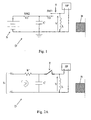
- the inductive proximity sensor D comprises:
- said supplying means consist basically of the capacity or capacitor C of the LC circuit.
- the LC circuit is repeatedly switched between two states, namely a first state in which the coil or inductance L is disconnected from the capacity C and said capacity C is charged and a second state in which the coil or inductance L is connected to the capacity C and said capacity C discharges through said coil or inductance L, the LC circuit being allowed to freely oscillate while in said second state and until the following change of state and the effective circuit parameters, and thus the oscillating voltage signal, being modified by the possible object(s) and/or body(ies) B located within the detection area, and in that a voltage signal amplitude measurement is performed at a certain predefined point of said oscillating voltage signal after each switching from the first to the second state and the result of said measurement is computed in connection with reference measurements in order to calculate the distance to the front working plane forming the active surface or end of the sensor D, the nature of the constituting material(s), and/or a mass indicative value of the object(s) or
- Said sensor D is preferably mounted in a tight stainless steel housing.
- the inductive coil may be placed in the open side of a ferrite cap, a metal plate being placed on the opened (working) surface of this cap, said surface forming the front working plane of the sensor D.
- the state of the LC circuit is defined by a switching means SM1 able to mutually connect or disconnect from each other the capacity C and the coil L, said switching means SM1 being driven by a periodical, for example rectangular or square, pulse signal with a predefined period T.
- the capacity C is connected to the opposite terminals of a DC voltage source S adapted to ensure its repeated charge during the first state durations of the LC circuit, a resistance R' being possibly serial connected between said source S and said capacitance C, said resistance R' possibly being the resistance of any component of said circuit or the sum of several of such resistances (switch, connections, ).
- the senor D can be designed with a single switching means SM1 controlling charge and discharge of the capacity C.
- the sensor D can comprise a second switching means SM2 able to mutually connect and disconnect from each other the source S and the capacitance C, said second switching means SM2 being driven in antiphase in comparison with the switching means SM1 connecting/disconnecting capacity C and coil L.
- Said sensor D is then operated as follows:
- the value of the capacity C and, should the case occur, the value of the resistance R' is(are) defined in such a way that the RC-constant, where R is the sum of the internal resistances of a source S and of the capacitance C with possibly the separate resistance R', is several times smaller than the pulse signal period T.
- the RC-constant is 2 to 10 times, preferably 3 to 5 times, smaller than the pulse signal period T.
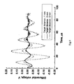
- the given moment at which the voltage amplitude measurement is performed at the opposite terminals of the coil or inductance L corresponds approximately to the maximum absolute amplitude value of the second or any further completely formed alternation of the decaying oscillating voltage signal recorded during a second state duration at said terminals, when the amplitude values are still important.
- the rank of the concerned alternation for measurement purposes in connection with the invention is preferably a compromise between a significant amplitude value and a reliable modulation depth, which becomes better as the rank of the considered alternation increases.
- the measurements can be done between the second and the fourth absolute maximum value.
- the recorded voltage signal at the terminals of the coil L is advantageously used to produce a differential signal (difference of coil voltages without and with an object or body in the proximity of the sensor) on which the topical voltage measurement can be performed. Said measured value is then transformed by the processing means SP into a linear value allowing to deduct the distance of the given object using a prerecorded linear function as shown by way of example on figure 5.
- the oscillation frequency of the LC or LRC circuit is preferably comprised between 10 kHz and 50 kHz, whereas the repetition frequency or switching frequency is comprised between 2 kHz and 10 kHz, the ratio between said frequencies being comprised between 1/4 and 1/6, preferably being around 1/5.
- the coil L had a diameter of 5,6 mm and an internal resistance of 2,6 ⁇ . Said coil was placed in a ferrite structure with an external diameter of 7, 25 mm. All the components were mounted in a stainless steel non magnetic housing with a front wall which was 1 mm thick (active surface of the sensor D) and the sensor D was used in a flush mounted configuration.
- the inductive proximity sensor D can non limitatively be used:
- the repeatedly acquired information about (an) object(s) or body(ies), in particular moving ones, located in the sensing or detection area of the sensor can be exploited either to give continuously data about the concerned object or body (distance, type of material, ...) or to issue binary data (by comparing the continuously acquired data to a threshold value).
- the present invention proposes an inductive sensor in a metal housing, based on a pulse oscillation technology.
Landscapes
- Electronic Switches (AREA)
- Switches That Are Operated By Magnetic Or Electric Fields (AREA)
- Geophysics And Detection Of Objects (AREA)
- Measurement Of Length, Angles, Or The Like Using Electric Or Magnetic Means (AREA)
Claims (11)
- Induktiver Näherungssensor (D) umfassend:- eine Induktionsspule (L), die eine vordere Arbeitsebene des Sensors (D) definiert und einer Abdeckplatte oder einem flachen Teil des Gehäuses des Sensors zugeordnet ist, wobei die Platte oder der Teil aus einem nicht magnetischen Metall mit geringer elektrischer Leitfähigkeit gefertigt ist und die Platte oder der Teil senkrecht zur Spulenachse und parallel zu ihrer vorderen Arbeitsebene angeordnet ist und somit Teil der magnetischen Ersatzschaltung bildet;- Mittel (C,S) zum mehrmaligen Zuführen von Strom an die Spule oder Induktivität;- Mittel (SP) zum Verarbeiten von Signalen, die den in die Spule oder Induktivität (L) beim Einspeisen induzierten Spannungen (V) entsprechen,wobei die induzierten Spannungen (V) durch die Anwesenheit von Objekten oder Körpern (B) innerhalb eines vorbestimmten Detektionsbereichs in Abhängigkeit deren Abstands und deren Materials oder deren Materialien, aus denen diese gebildet sind, beeinflusst werden, und wobei die Spule oder Induktivität (L) Teil einer parallelen LC-Schaltung ist;
wobei der Sensor dadurch gekennzeichnet ist, dass die Zuführmittel im Wesentlichen aus der Kapazität oder dem Kondensator (C) der LC-Schaltung besteht, und dass die LC-Schaltung mehrmalig zwischen zwei Zuständen geschaltet wird, nämlich einem ersten Zustand, in welchem die Spule oder Induktivität (L) von der Kapazität (C) getrennt ist und die Kapazität (C) geladen ist, und einem zweiten Zustand, in welchem die Spule oder Induktivität (L) mit der Kapazität (C) verbunden ist und die Kapazität (C) durch die Spule oder Induktivität (L) entlädt, wobei die LC-Schaltung, wenn sie in dem zweiten Zustand ist, bis zu der darauf folgenden Änderung des Zustands frei oszillieren kann, und die effektiven Schaltungsparameter und somit das oszillierende Spannungssignal durch das Objekt oder die Objekte und/oder dem oder die Körper (B), die innerhalb des Detektionsbereichs angeordnet sind, modifiziert werden, und dass eine Messung der Spannungsoszillationsamplitude an einem bestimmten, vorab definierten Punkt des Spannungssignals nach jedem Schalten von dem ersten in den zweiten Zustand ausgeführt wird und das Messergebnis in Verbindung mit Referenzmessungen berechnet wird, um den Abstand zu der vorderen Arbeitsebene, die die aktive Oberfläche oder das Ende des Sensors (D) bildet, die Beschaffenheit des/der diese bildenden Materials/Materialien und/oder einen die Masse anzeigenden Wert des Objekts oder der Objekte oder Körper (B), die innerhalb des Detektionsbereichs angeordnet sind, zu berechnen. - Induktiver Näherungssensor nach Anspruch 1, dadurch gekennzeichnet, dass der Zustand der LC-Schaltung durch eine Schalteinrichtung (SM1) definiert ist, die die Kapazität (C) und die Spule (L) beidseitig verbinden oder trennen kann, wobei die Schalteinrichtung (SM1) von einem periodischen, z.B. rechteckigen oder quadratischen, Impulssignal mit einer vorbestimmten Periode (T) angesteuert wird.
- Induktiver Näherungssensor nach Anspruch 1 oder 2, dadurch gekennzeichnet, dass die Kapazität (C) mit den gegenüberliegenden Anschlüssen einer Gleichspannungsquelle (S) verbunden ist, die so ausgebildet ist, dass sie ihre mehrmalige Ladung während der Dauer des ersten Zustands der LC-Schaltung sicherstellt, wobei ein Widerstand (R') möglicherweise in Reihe zwischen der Quelle (S) und der Kapazität (C) geschaltet ist.
- Induktiver Näherungssensor nach Anspruch 3 in Abhängigkeit von Anspruch 2, dadurch gekennzeichnet, dass er eine zweite Schalteinrichtung (SM2) aufweist, die die Quelle (S) und die Kapazität (C) beidseitig verbinden und trennen kann, wobei die zweite Schalteinrichtung (SM2) gegenphasig zu der Schalteinrichtung (SM1) Verbindungs/Trennkapazität (C) und Spule (L) angesteuert wird.
- Induktiver Näherungssensor nach Anspruch 2 oder einem der Ansprüche 3 und 4, in Abhängigkeit von Anspruch 2, dadurch gekennzeichnet, dass die Größe der Kapazität (C) und gegebenenfalls die Größe des Widerstands (R') so definiert sind/ist, dass die RC-Konstante ein mehrfaches kleiner als die Impulssignalperiode (T) ist, wobei R die Summe der Innenwiderstände einer Quelle (S) und der Kapazität (C) mit möglicherweise dem Trennwiderstand (R') ist.
- Induktiver Näherungssensor nach Anspruch 5, dadurch gekennzeichnet, dass die RC-Konstante 2 bis 10 mal, vorzugsweise 3 bis 5 mal kleiner als die Impulssignalperiode (T) ist.
- Induktiver Näherungssensor nach einem der Ansprüche 1 bis 6, dadurch gekennzeichnet, dass der vorgegebene Moment, in welchem die Spannungsamplitudenmessung an den gegenüberliegenden Anschlüssen der Spule oder Induktivität (L) ausgeführt wird, ungefähr dem maximalen absoluten Amplitudenwert der zweiten oder jeglichen weiteren vollständig gebildeten Halbwelle des abfallenden, während der Dauer eines zweiten Zustands an den Anschlüssen aufgezeichneten Oszillationsspannungssignals entspricht.
- Induktiver Näherungssensor nach einem der Ansprüche 1 bis 7, dadurch gekennzeichnet, dass die Verzögerung zum Ausführen der Messung des Spannungswerts an der Spule oder Induktivität (L) gegenüber den Anschlüssen nach dem Schalten der LC- oder LRC-Schaltung von ihrem ersten Zustand in ihren zweiten Zustand berechnet wird unter Verwendung der Zeitabhängigkeit der Modulationstiefe oder des Modulationsgrades, um ihren Wert auf der Basis einer linearen Funktion zu optimieren.
 UL0(t) ist die Spulenspannung ohne jegliche Beeinflussung, undUL1(t) ist die Spulenspannung, wobei ein Objekt oder Körper sich innerhalb des Detektionsbereichs befindet und die Spannung beeinflusst.
 - Induktiver Näherungssensor nach einem der Ansprüche 1 bis 8, dadurch gekennzeichnet, dass der Sensor (D) in einem engen Edelstahlgehäuse angebracht ist.
- Verwendung eines induktiven Näherungssensors zum Detektieren der Anwesenheit und des Abstands eines vorgegebenen ferromagnetischen oder nicht ferromagnetischen Metallobjektes oder -körpers in einem vorbestimmten Detektionsbereich.
- Verwendung eines induktiven Näherungssensors zum Detektieren und Unterscheiden von Objekten oder Körpern, die aus unterschiedlichen ferromagnetischen und/oder nicht ferromagnetischen Metallmaterialien gefertigt sind oder zumindest teilweise damit überzogen sind, und in einem vorbestimmten Detektionsbereich vorhanden sind.
Priority Applications (7)
| Application Number | Priority Date | Filing Date | Title |
|---|---|---|---|
| EP04360032A EP1580889B1 (de) | 2004-03-26 | 2004-03-26 | Induktiver Annäherungssensor |
| ES04360032T ES2297359T3 (es) | 2004-03-26 | 2004-03-26 | Sensor de proximidad inductivo. |
| PT04360032T PT1580889E (pt) | 2004-03-26 | 2004-03-26 | Sensor de proximidade indutivo |
| AT04360032T ATE380411T1 (de) | 2004-03-26 | 2004-03-26 | Induktiver annäherungssensor |
| DE602004010486T DE602004010486T2 (de) | 2004-03-26 | 2004-03-26 | Induktiver Annäherungssensor |
| JP2005078653A JP4750439B2 (ja) | 2004-03-26 | 2005-03-18 | 誘導近接センサ |
| US11/090,161 US7586303B2 (en) | 2004-03-26 | 2005-03-28 | Inductive proximity sensor |
Applications Claiming Priority (1)
| Application Number | Priority Date | Filing Date | Title |
|---|---|---|---|
| EP04360032A EP1580889B1 (de) | 2004-03-26 | 2004-03-26 | Induktiver Annäherungssensor |
Publications (2)
| Publication Number | Publication Date |
|---|---|
| EP1580889A1 EP1580889A1 (de) | 2005-09-28 |
| EP1580889B1 true EP1580889B1 (de) | 2007-12-05 |
Family
ID=34854737
Family Applications (1)
| Application Number | Title | Priority Date | Filing Date |
|---|---|---|---|
| EP04360032A Expired - Lifetime EP1580889B1 (de) | 2004-03-26 | 2004-03-26 | Induktiver Annäherungssensor |
Country Status (7)
| Country | Link |
|---|---|
| US (1) | US7586303B2 (de) |
| EP (1) | EP1580889B1 (de) |
| JP (1) | JP4750439B2 (de) |
| AT (1) | ATE380411T1 (de) |
| DE (1) | DE602004010486T2 (de) |
| ES (1) | ES2297359T3 (de) |
| PT (1) | PT1580889E (de) |
Families Citing this family (25)
| Publication number | Priority date | Publication date | Assignee | Title |
|---|---|---|---|---|
| US6812718B1 (en) | 1999-05-27 | 2004-11-02 | Nanonexus, Inc. | Massively parallel interface for electronic circuits |
| DE102005061868A1 (de) * | 2005-12-23 | 2007-07-05 | Robert Bosch Gmbh | Vorrichtung zur Bestimmung eines Gegenstands, insbesondere Ortungsgerät und Materialerkennungsgerät |
| ES2763573T3 (es) | 2007-02-27 | 2020-05-29 | Senstronic S A | Sensor inductivo de presencia o posición |
| DE102007009994A1 (de) * | 2007-03-01 | 2008-09-04 | Robert Bosch Gmbh | Induktiver Sensor |
| US8427137B2 (en) * | 2007-12-14 | 2013-04-23 | Mts Systems Corporation | Magnetostrictive displacement transducer with suppression of switching power supply noise |
| IT1392204B1 (it) * | 2008-11-24 | 2012-02-22 | M D Micro Detectors S P A | Sensore induttivo ad uscita indipendente dal tipo di materiale metallico rilevato |
| JP2010167147A (ja) * | 2009-01-23 | 2010-08-05 | Technos Japan:Kk | 寝具から人が離床したことを識別する識別装置およびその識別方法 |
| US8115498B1 (en) | 2009-10-02 | 2012-02-14 | The Boeing Company | Proximity sensor interface device and method for its use |
| US8766649B1 (en) | 2009-10-02 | 2014-07-01 | The Boeing Company | Proximity sensor interface device and method for its use |
| US20110101967A1 (en) * | 2009-11-02 | 2011-05-05 | Rockwell Automation Technologies, Inc. | Enhanced performance proximity sensor |
| FR2960068B1 (fr) * | 2010-05-12 | 2013-06-07 | Senstronic | Dispositif de detection et de denombrement d'elements metalliques |
| US8631168B2 (en) * | 2010-06-28 | 2014-01-14 | VIZIO Inc. | Input selection mechanism for a display device |
| KR101206069B1 (ko) | 2010-12-30 | 2012-11-28 | 주식회사 트루윈 | 스위칭소자를 이용한 인덕턴스방식 변위감지센서 |
| US8606424B2 (en) * | 2011-04-05 | 2013-12-10 | King Fahd University Of Petroleum And Minerals | Particle swarm optimization system and method for microgrids |
| FR2974175B1 (fr) | 2011-04-14 | 2013-10-11 | Mecanique Magnetique Sa | Dispositif de detection de la position axiale d'un arbre tournant et application a une pompe turbo-moleculaire |
| DE102011102796A1 (de) * | 2011-05-23 | 2012-11-29 | Trw Automotive Electronics & Components Gmbh | Positionssensor, Aktor-Sensor-Vorrichtung und Verfahren zur induktiven Erfassung einer Position |
| US10523199B2 (en) * | 2011-12-20 | 2019-12-31 | Robert Hooper | Housings for inductive proximity sensors |
| ITUB20153537A1 (it) * | 2015-09-10 | 2017-03-10 | St Microelectronics Srl | Procedimento di funzionamento di sensori lc, sistema ed apparecchiatura corrispondenti |
| FR3049068B1 (fr) | 2016-03-16 | 2018-04-06 | Senstronic | Dispositif detecteur inductif de facteur 1 |
| DE102018211029A1 (de) | 2017-12-20 | 2019-06-27 | Gerd Reime | Verfahren und Sensor zur Erkennung einer Bewegung eines metallischen Gegenstandes mit extrem geringem Stromverbrauch |
| CN108983086B (zh) * | 2018-09-06 | 2023-11-17 | 佛山市顺德区美的洗涤电器制造有限公司 | 旋钮开关状态检测方法、装置、系统及设备 |
| CN109557175A (zh) * | 2018-12-17 | 2019-04-02 | 南京宏光汽车附件有限公司 | 槽型座断爪与变形无损检测装置 |
| EP3923478A1 (de) | 2020-06-10 | 2021-12-15 | Simmonds Precision Products, Inc. | Näherungssensor und verwendungsverfahren dafür |
| FR3147364B1 (fr) * | 2023-03-31 | 2025-05-09 | Commissariat Energie Atomique | Capteur inductif à haute résolution |
| FR3152874B1 (fr) | 2023-09-12 | 2025-10-03 | Senstronic | Détecteur avec fonction de maintien intégrée |
Family Cites Families (14)
| Publication number | Priority date | Publication date | Assignee | Title |
|---|---|---|---|---|
| FR2561001B1 (fr) * | 1984-03-09 | 1986-10-31 | Petercem Sa | Capteur de la position relative d'une cible par rapport a une cible de reference |
| FR2604251B1 (fr) * | 1986-09-19 | 1990-11-16 | Telemecanique Electrique | Detecteur inductif de proximite muni d'un circuit oscillant a relaxation |
| FR2614431B1 (fr) * | 1987-04-23 | 1989-06-16 | Telemecanique Electrique | Circuit de traitement d'un signal pseudo-oscillatoire, notamment pour detecteur de proximite inductif |
| FR2614432B1 (fr) * | 1987-04-23 | 1989-07-28 | Telemecanique Electrique | Detecteur de proximite inductif |
| JPS63316515A (ja) * | 1987-06-19 | 1988-12-23 | Nec Corp | 近接センサ |
| DE3733943A1 (de) * | 1987-10-07 | 1989-04-20 | Andrae Leonberg Gmbh | Verfahren und vorrichtung zur erregung eines schwingkreises |
| JPH0613876A (ja) * | 1992-06-26 | 1994-01-21 | Omron Corp | 近接スイッチ |
| JPH06164358A (ja) * | 1993-02-18 | 1994-06-10 | Omron Corp | 近接センサ |
| US5801530A (en) * | 1995-04-17 | 1998-09-01 | Namco Controls Corporation | Proximity sensor having a non-ferrous metal shield for enhanced sensing range |
| AT412636B (de) * | 2000-02-23 | 2005-05-25 | Vae Eisenbahnsysteme Gmbh | Einrichtung zur überwachung und prognose der ausfallwahrscheinlichkeit von induktiven näherungssensoren |
| FR2806808B1 (fr) * | 2000-03-24 | 2002-05-24 | Ela Medical Sa | Circuit de detection de la presence d'un aimant permanent au voisinage d'un dispositif medical actif, notamment d'un stimulateur cardiaque, defibrillateur, cardioverteur et/ou dispositif multisite |
| DE10030952A1 (de) * | 2000-06-24 | 2002-01-03 | Atmel Germany Gmbh | Verfahren zur Reduzierung der Abkling- und Einschwingzeiten bei Schwingkreisen |
| US6650111B2 (en) * | 2001-07-18 | 2003-11-18 | Eaton Corporation | Pulsed excited proximity sensor |
| FR2827677B1 (fr) * | 2001-07-19 | 2003-10-31 | Senstronic Sa | Procede de detection d'un objet en un materiau conducteur et capteur correspondant |
-
2004
- 2004-03-26 PT PT04360032T patent/PT1580889E/pt unknown
- 2004-03-26 EP EP04360032A patent/EP1580889B1/de not_active Expired - Lifetime
- 2004-03-26 ES ES04360032T patent/ES2297359T3/es not_active Expired - Lifetime
- 2004-03-26 DE DE602004010486T patent/DE602004010486T2/de not_active Expired - Lifetime
- 2004-03-26 AT AT04360032T patent/ATE380411T1/de active
-
2005
- 2005-03-18 JP JP2005078653A patent/JP4750439B2/ja not_active Expired - Lifetime
- 2005-03-28 US US11/090,161 patent/US7586303B2/en active Active
Also Published As
| Publication number | Publication date |
|---|---|
| US20050212510A1 (en) | 2005-09-29 |
| ATE380411T1 (de) | 2007-12-15 |
| US7586303B2 (en) | 2009-09-08 |
| EP1580889A1 (de) | 2005-09-28 |
| PT1580889E (pt) | 2008-03-17 |
| JP4750439B2 (ja) | 2011-08-17 |
| JP2005287020A (ja) | 2005-10-13 |
| DE602004010486T2 (de) | 2008-11-13 |
| DE602004010486D1 (de) | 2008-01-17 |
| ES2297359T3 (es) | 2008-05-01 |
Similar Documents
| Publication | Publication Date | Title |
|---|---|---|
| EP1580889B1 (de) | Induktiver Annäherungssensor | |
| US6882162B2 (en) | System for the wireless transmission of information and/or energy between a removable vehicle seat and the vehicle body | |
| US4950985A (en) | Apparatus for measuring electromagnetic values of a coil, in particular for measuring the position of armature of a coil/armature magnetic system | |
| US11027619B2 (en) | Charging station, motor vehicle and method for inductive charging of a battery of a motor vehicle | |
| US20210164766A1 (en) | Electronic appliance with inductive sensor | |
| AU2003227757A1 (en) | Phase discrimination for micro electrical measurement in non-conductive fluid | |
| GB2063485A (en) | Contactless Detection of the Distance of a Metal Surface from a Counter-surface | |
| US7574924B1 (en) | Magnetic flow meter | |
| US5198764A (en) | Position detector apparatus and method utilizing a transient voltage waveform processor | |
| EP0529181A2 (de) | Methode und Gerät zum Auffinden von Stahlarmierungen in Beton | |
| EP0856722B1 (de) | Längenmessapparat unter Verwendung einer magnetostriktiven Verzögerungsleitung | |
| EP3096457A1 (de) | Näherungssensor | |
| US5574366A (en) | Proximity switch having a variable sensing resistor for maintaining a constant total resistance | |
| US4475089A (en) | Proximity detector | |
| US6304075B1 (en) | Magnetic resonance sensor | |
| JP2001241983A (ja) | 電磁流量計 | |
| EP1143225A3 (de) | Kapazitiver Sensor | |
| JPH0634307A (ja) | 静電容量形変位センサ | |
| GB2169710A (en) | Process and apparatus for measuring the distance between a target and a sensor | |
| US6597186B2 (en) | Through tank level gauging | |
| JP3075432B2 (ja) | タイヤ監視装置 | |
| EP3141871B1 (de) | Verfahren für den betrieb von lc-sensoren, entsprechendes system und vorrichtung | |
| KR100370484B1 (ko) | 금속물체의 검출장치 | |
| JP2003156304A (ja) | 流体圧シリンダにおける位置検出器 | |
| JPH0729466A (ja) | 近接スイッチ |
Legal Events
| Date | Code | Title | Description |
|---|---|---|---|
| PUAI | Public reference made under article 153(3) epc to a published international application that has entered the european phase |
Free format text: ORIGINAL CODE: 0009012 |
|
| AK | Designated contracting states |
Kind code of ref document: A1 Designated state(s): AT BE BG CH CY CZ DE DK EE ES FI FR GB GR HU IE IT LI LU MC NL PL PT RO SE SI SK TR |
|
| AX | Request for extension of the european patent |
Extension state: AL LT LV MK |
|
| 17P | Request for examination filed |
Effective date: 20051214 |
|
| AKX | Designation fees paid |
Designated state(s): AT BE BG CH CY CZ DE DK EE ES FI FR GB GR HU IE IT LI LU MC NL PL PT RO SE SI SK TR |
|
| GRAP | Despatch of communication of intention to grant a patent |
Free format text: ORIGINAL CODE: EPIDOSNIGR1 |
|
| GRAS | Grant fee paid |
Free format text: ORIGINAL CODE: EPIDOSNIGR3 |
|
| GRAA | (expected) grant |
Free format text: ORIGINAL CODE: 0009210 |
|
| AK | Designated contracting states |
Kind code of ref document: B1 Designated state(s): AT BE BG CH CY CZ DE DK EE ES FI FR GB GR HU IE IT LI LU MC NL PL PT RO SE SI SK TR |
|
| REG | Reference to a national code |
Ref country code: GB Ref legal event code: FG4D |
|
| REG | Reference to a national code |
Ref country code: IE Ref legal event code: FG4D |
|
| REG | Reference to a national code |
Ref country code: CH Ref legal event code: EP |
|
| REF | Corresponds to: |
Ref document number: 602004010486 Country of ref document: DE Date of ref document: 20080117 Kind code of ref document: P |
|
| REG | Reference to a national code |
Ref country code: PT Ref legal event code: SC4A Free format text: AVAILABILITY OF NATIONAL TRANSLATION Effective date: 20080303 |
|
| REG | Reference to a national code |
Ref country code: CH Ref legal event code: NV Representative=s name: ABACUS PATENTANWAELTE KLOCKE SPAETH BARTH |
|
| PG25 | Lapsed in a contracting state [announced via postgrant information from national office to epo] |
Ref country code: SE Free format text: LAPSE BECAUSE OF FAILURE TO SUBMIT A TRANSLATION OF THE DESCRIPTION OR TO PAY THE FEE WITHIN THE PRESCRIBED TIME-LIMIT Effective date: 20080305 Ref country code: NL Free format text: LAPSE BECAUSE OF FAILURE TO SUBMIT A TRANSLATION OF THE DESCRIPTION OR TO PAY THE FEE WITHIN THE PRESCRIBED TIME-LIMIT Effective date: 20071205 |
|
| REG | Reference to a national code |
Ref country code: ES Ref legal event code: FG2A Ref document number: 2297359 Country of ref document: ES Kind code of ref document: T3 |
|
| PG25 | Lapsed in a contracting state [announced via postgrant information from national office to epo] |
Ref country code: SI Free format text: LAPSE BECAUSE OF FAILURE TO SUBMIT A TRANSLATION OF THE DESCRIPTION OR TO PAY THE FEE WITHIN THE PRESCRIBED TIME-LIMIT Effective date: 20071205 Ref country code: PL Free format text: LAPSE BECAUSE OF FAILURE TO SUBMIT A TRANSLATION OF THE DESCRIPTION OR TO PAY THE FEE WITHIN THE PRESCRIBED TIME-LIMIT Effective date: 20071205 Ref country code: FI Free format text: LAPSE BECAUSE OF FAILURE TO SUBMIT A TRANSLATION OF THE DESCRIPTION OR TO PAY THE FEE WITHIN THE PRESCRIBED TIME-LIMIT Effective date: 20071205 |
|
| NLV1 | Nl: lapsed or annulled due to failure to fulfill the requirements of art. 29p and 29m of the patents act | ||
| PG25 | Lapsed in a contracting state [announced via postgrant information from national office to epo] |
Ref country code: CZ Free format text: LAPSE BECAUSE OF FAILURE TO SUBMIT A TRANSLATION OF THE DESCRIPTION OR TO PAY THE FEE WITHIN THE PRESCRIBED TIME-LIMIT Effective date: 20071205 |
|
| ET | Fr: translation filed | ||
| PG25 | Lapsed in a contracting state [announced via postgrant information from national office to epo] |
Ref country code: SK Free format text: LAPSE BECAUSE OF FAILURE TO SUBMIT A TRANSLATION OF THE DESCRIPTION OR TO PAY THE FEE WITHIN THE PRESCRIBED TIME-LIMIT Effective date: 20071205 Ref country code: RO Free format text: LAPSE BECAUSE OF FAILURE TO SUBMIT A TRANSLATION OF THE DESCRIPTION OR TO PAY THE FEE WITHIN THE PRESCRIBED TIME-LIMIT Effective date: 20071205 |
|
| REG | Reference to a national code |
Ref country code: HU Ref legal event code: AG4A Ref document number: E003389 Country of ref document: HU |
|
| PLBE | No opposition filed within time limit |
Free format text: ORIGINAL CODE: 0009261 |
|
| STAA | Information on the status of an ep patent application or granted ep patent |
Free format text: STATUS: NO OPPOSITION FILED WITHIN TIME LIMIT |
|
| PG25 | Lapsed in a contracting state [announced via postgrant information from national office to epo] |
Ref country code: DK Free format text: LAPSE BECAUSE OF FAILURE TO SUBMIT A TRANSLATION OF THE DESCRIPTION OR TO PAY THE FEE WITHIN THE PRESCRIBED TIME-LIMIT Effective date: 20071205 Ref country code: MC Free format text: LAPSE BECAUSE OF NON-PAYMENT OF DUE FEES Effective date: 20080331 |
|
| 26N | No opposition filed |
Effective date: 20080908 |
|
| PG25 | Lapsed in a contracting state [announced via postgrant information from national office to epo] |
Ref country code: EE Free format text: LAPSE BECAUSE OF FAILURE TO SUBMIT A TRANSLATION OF THE DESCRIPTION OR TO PAY THE FEE WITHIN THE PRESCRIBED TIME-LIMIT Effective date: 20071205 Ref country code: GR Free format text: LAPSE BECAUSE OF FAILURE TO SUBMIT A TRANSLATION OF THE DESCRIPTION OR TO PAY THE FEE WITHIN THE PRESCRIBED TIME-LIMIT Effective date: 20080306 Ref country code: IE Free format text: LAPSE BECAUSE OF NON-PAYMENT OF DUE FEES Effective date: 20080326 |
|
| PG25 | Lapsed in a contracting state [announced via postgrant information from national office to epo] |
Ref country code: BG Free format text: LAPSE BECAUSE OF FAILURE TO SUBMIT A TRANSLATION OF THE DESCRIPTION OR TO PAY THE FEE WITHIN THE PRESCRIBED TIME-LIMIT Effective date: 20080305 |
|
| PG25 | Lapsed in a contracting state [announced via postgrant information from national office to epo] |
Ref country code: CY Free format text: LAPSE BECAUSE OF FAILURE TO SUBMIT A TRANSLATION OF THE DESCRIPTION OR TO PAY THE FEE WITHIN THE PRESCRIBED TIME-LIMIT Effective date: 20071205 |
|
| PG25 | Lapsed in a contracting state [announced via postgrant information from national office to epo] |
Ref country code: LU Free format text: LAPSE BECAUSE OF NON-PAYMENT OF DUE FEES Effective date: 20080326 |
|
| PG25 | Lapsed in a contracting state [announced via postgrant information from national office to epo] |
Ref country code: TR Free format text: LAPSE BECAUSE OF FAILURE TO SUBMIT A TRANSLATION OF THE DESCRIPTION OR TO PAY THE FEE WITHIN THE PRESCRIBED TIME-LIMIT Effective date: 20071205 |
|
| REG | Reference to a national code |
Ref country code: FR Ref legal event code: PLFP Year of fee payment: 13 |
|
| REG | Reference to a national code |
Ref country code: FR Ref legal event code: PLFP Year of fee payment: 14 |
|
| REG | Reference to a national code |
Ref country code: FR Ref legal event code: PLFP Year of fee payment: 15 |
|
| PGFP | Annual fee paid to national office [announced via postgrant information from national office to epo] |
Ref country code: FR Payment date: 20230322 Year of fee payment: 20 Ref country code: AT Payment date: 20230322 Year of fee payment: 20 |
|
| PGFP | Annual fee paid to national office [announced via postgrant information from national office to epo] |
Ref country code: PT Payment date: 20230316 Year of fee payment: 20 Ref country code: HU Payment date: 20230323 Year of fee payment: 20 Ref country code: GB Payment date: 20230321 Year of fee payment: 20 Ref country code: DE Payment date: 20230321 Year of fee payment: 20 Ref country code: BE Payment date: 20230321 Year of fee payment: 20 |
|
| P01 | Opt-out of the competence of the unified patent court (upc) registered |
Effective date: 20230621 |
|
| PGFP | Annual fee paid to national office [announced via postgrant information from national office to epo] |
Ref country code: IT Payment date: 20230328 Year of fee payment: 20 Ref country code: ES Payment date: 20230527 Year of fee payment: 20 Ref country code: CH Payment date: 20230401 Year of fee payment: 20 |
|
| REG | Reference to a national code |
Ref country code: DE Ref legal event code: R071 Ref document number: 602004010486 Country of ref document: DE |
|
| REG | Reference to a national code |
Ref country code: CH Ref legal event code: PL |
|
| REG | Reference to a national code |
Ref country code: BE Ref legal event code: MK Effective date: 20240326 Ref country code: ES Ref legal event code: FD2A Effective date: 20240404 |
|
| PG25 | Lapsed in a contracting state [announced via postgrant information from national office to epo] |
Ref country code: ES Free format text: LAPSE BECAUSE OF EXPIRATION OF PROTECTION Effective date: 20240327 |
|
| REG | Reference to a national code |
Ref country code: GB Ref legal event code: PE20 Expiry date: 20240325 |
|
| PG25 | Lapsed in a contracting state [announced via postgrant information from national office to epo] |
Ref country code: ES Free format text: LAPSE BECAUSE OF EXPIRATION OF PROTECTION Effective date: 20240327 Ref country code: GB Free format text: LAPSE BECAUSE OF EXPIRATION OF PROTECTION Effective date: 20240325 |
|
| REG | Reference to a national code |
Ref country code: AT Ref legal event code: MK07 Ref document number: 380411 Country of ref document: AT Kind code of ref document: T Effective date: 20240326 |
|
| PG25 | Lapsed in a contracting state [announced via postgrant information from national office to epo] |
Ref country code: PT Free format text: LAPSE BECAUSE OF EXPIRATION OF PROTECTION Effective date: 20240404 |
|
| PG25 | Lapsed in a contracting state [announced via postgrant information from national office to epo] |
Ref country code: PT Free format text: LAPSE BECAUSE OF EXPIRATION OF PROTECTION Effective date: 20240404 |