EP3141871B1 - Verfahren für den betrieb von lc-sensoren, entsprechendes system und vorrichtung - Google Patents
Verfahren für den betrieb von lc-sensoren, entsprechendes system und vorrichtung Download PDFInfo
- Publication number
- EP3141871B1 EP3141871B1 EP16162411.9A EP16162411A EP3141871B1 EP 3141871 B1 EP3141871 B1 EP 3141871B1 EP 16162411 A EP16162411 A EP 16162411A EP 3141871 B1 EP3141871 B1 EP 3141871B1
- Authority
- EP
- European Patent Office
- Prior art keywords
- sensor
- energy
- ref
- switch
- reference capacitor
- Prior art date
- Legal status (The legal status is an assumption and is not a legal conclusion. Google has not performed a legal analysis and makes no representation as to the accuracy of the status listed.)
- Active
Links
Images


Classifications
-
- G—PHYSICS
- G01—MEASURING; TESTING
- G01R—MEASURING ELECTRIC VARIABLES; MEASURING MAGNETIC VARIABLES
- G01R27/00—Arrangements for measuring resistance, reactance, impedance, or electric characteristics derived therefrom
- G01R27/02—Measuring real or complex resistance, reactance, impedance, or other two-pole characteristics derived therefrom, e.g. time constant
- G01R27/26—Measuring inductance or capacitance; Measuring quality factor, e.g. by using the resonance method; Measuring loss factor; Measuring dielectric constants ; Measuring impedance or related variables
-
- G—PHYSICS
- G01—MEASURING; TESTING
- G01D—MEASURING NOT SPECIALLY ADAPTED FOR A SPECIFIC VARIABLE; ARRANGEMENTS FOR MEASURING TWO OR MORE VARIABLES NOT COVERED IN A SINGLE OTHER SUBCLASS; TARIFF METERING APPARATUS; MEASURING OR TESTING NOT OTHERWISE PROVIDED FOR
- G01D5/00—Mechanical means for transferring the output of a sensing member; Means for converting the output of a sensing member to another variable where the form or nature of the sensing member does not constrain the means for converting; Transducers not specially adapted for a specific variable
- G01D5/12—Mechanical means for transferring the output of a sensing member; Means for converting the output of a sensing member to another variable where the form or nature of the sensing member does not constrain the means for converting; Transducers not specially adapted for a specific variable using electric or magnetic means
- G01D5/14—Mechanical means for transferring the output of a sensing member; Means for converting the output of a sensing member to another variable where the form or nature of the sensing member does not constrain the means for converting; Transducers not specially adapted for a specific variable using electric or magnetic means influencing the magnitude of a current or voltage
- G01D5/20—Mechanical means for transferring the output of a sensing member; Means for converting the output of a sensing member to another variable where the form or nature of the sensing member does not constrain the means for converting; Transducers not specially adapted for a specific variable using electric or magnetic means influencing the magnitude of a current or voltage by varying inductance, e.g. by a movable armature
-
- H—ELECTRICITY
- H03—ELECTRONIC CIRCUITRY
- H03K—PULSE TECHNIQUE
- H03K17/00—Electronic switching or gating, i.e. not by contact-making and –breaking
- H03K17/94—Electronic switching or gating, i.e. not by contact-making and –breaking characterised by the way in which the control signals are generated
- H03K17/945—Proximity switches
- H03K17/95—Proximity switches using a magnetic detector
- H03K17/952—Proximity switches using a magnetic detector using inductive coils
- H03K17/9537—Proximity switches using a magnetic detector using inductive coils in a resonant circuit
-
- H—ELECTRICITY
- H03—ELECTRONIC CIRCUITRY
- H03K—PULSE TECHNIQUE
- H03K17/00—Electronic switching or gating, i.e. not by contact-making and –breaking
- H03K17/94—Electronic switching or gating, i.e. not by contact-making and –breaking characterised by the way in which the control signals are generated
- H03K17/945—Proximity switches
- H03K17/95—Proximity switches using a magnetic detector
- H03K17/952—Proximity switches using a magnetic detector using inductive coils
- H03K17/9537—Proximity switches using a magnetic detector using inductive coils in a resonant circuit
- H03K17/954—Proximity switches using a magnetic detector using inductive coils in a resonant circuit controlled by an oscillatory signal
Definitions
- the description relates to inductive (LC) sensors.
- One or more embodiments may apply to LC sensors for use, e.g. in fluid metering applications, such as water and gas meters.
- Inductive sensing is based on an inductor-capacitor resonant circuit (which explains the current designation of "LC sensing") which is pumped by an oscillator with the inductor acting as a sensing coil.
- LC sensing current designation of "LC sensing”
- a conductive (e.g. metal) object comes in the vicinity of the coil, currents are generated in the object depending on various parameters such as e.g. the material and dimensions of the object and/or the distance to the sensing coil.
- the currents thus generated form a magnetic field which reduces the oscillation amplitude of the resonant circuit (tank) thus changing the parallel resonance impedance of the circuit. Detecting/measuring such change may be exploited for various sensing purposes.
- Inductive/LC sensing may be used in various industrial fields for e.g. various types of contactless sensing of moving parts for various purposes such as detecting/measuring distance, speed or flow.
- inductive/LC sensing is being increasingly applied e.g. in water and gas meter applications with the possibility of offering power/efficient solution adapted to be directly embedded e.g.in MicroController Units - MCUs.
- factors such as e.g. reducing the number of (analog) components coupled with the sensor, facilitating digital processing of the sensing signals and simplifying control logic while providing reduced consumption may play a significant role.
- Time-based LC sensor excitation using e.g. a high-speed (e.g. 4MHz) clock source to control transfer of energy during excitation has been used with potential drawbacks represented e.g. by power consumption and total measurement times in the range of e.g. 50 microseconds.
- the present invention relates to a method of operating LC sensors according to the preamble of claim 1, which is known, e.g. from US 4618835 A . Also, documents GB 2204135 A and US 2008/204206 A1 are of interest for the invention.
- An object of one or more embodiments is to provide a response to such a need.
- such an object may be achieved thanks to a method having the features set forth in claim 1 that follows.
- One or more embodiments may also relate to a corresponding device according to claim 4 as well as to apparatus (e.g. metering device such as a water or gas meter) according to claim 8 including such a device.
- apparatus e.g. metering device such as a water or gas meter
- references to "an embodiment” or “one embodiment” in the framework of the present description is intended to indicate that a particular configuration, structure, or characteristic described in relation to the embodiment is comprised in at least one embodiment.
- phrases such as “in an embodiment” or “in one embodiment” that may be present in one or more points of the present description do not necessarily refer to one and the same embodiment.
- particular conformations, structures, or characteristics may be combined in any adequate way in one or more embodiments.
- FIG. 1 The schematic diagram of Figure 1 is generally exemplary of possible applications of inductive/LC sensing: these designations will be hereinafter used as synonyms having regard to the general principle of operation of such sensors as summarized in the introduction of this description.
- FIG. 1 The schematic diagram of Figure 1 is exemplary of a possible application of inductive/LC sensors 10 in a fluid metering device such as a flow-meter (e.g. water or gas meter) in order to detect/measure fluid flow in a conduit C. This may take place, in manner known per se, by detecting/measuring movement of a rotary sensing plate P which is driven in rotation by fluid flow in the conduit C.
- a fluid metering device such as a flow-meter (e.g. water or gas meter)
- a fluid meter e.g. water or gas meter
- the rotary plate P may include complementary portions of different materials (e.g. conductive and non-conductive).
- One or more LC sensors 10 arranged facing the plate P may thus produce signals indicative of rotation of the plate P (and thus of the flow in the conduit C) for processing in e.g. a MicroController Unit - MCU.
- operation of an LC sensor 10 as exemplified herein may generally involve at least one charging phase wherein excitation energy for the sensor 10 is accumulated.
- the LC sensor (here exemplified as the parallel connection of an inductor L s and a capacitor C s ) may thus oscillate energized by the energy accumulated to permit sensing to take place as outlined in the introduction to this description.
- energy accumulation may be stopped at a certain time as defined e.g. by a high-frequency (e.g. 4MHz clock source).
- a high-frequency e.g. 4MHz clock source
- one or more embodiments as exemplified herein may provide for detecting (e.g. by a charge sensor/energy meter 12) the fact that the energy accumulated has reached a certain charge accumulation threshold, with operation switched towards the sensing phase when the charge threshold is detected to be reached.
- the excitation energy from an electric energy source V may be accumulated by charging a reference capacitor C ref .
- One or more embodiments as exemplified in Figure 2 may include a first switch S1 ad a second switch S2 (e.g. electronic switches such as MOSFETs) switchable under the control of an energy meter 12 configured for sensing the charge on the reference capacitor C ref (e.g. the voltage across the reference capacitor Cref).
- a first switch S1 ad e.g. electronic switches such as MOSFETs
- a second switch S2 e.g. electronic switches such as MOSFETs
- an energy meter 12 configured for sensing the charge on the reference capacitor C ref (e.g. the voltage across the reference capacitor Cref).
- the switch S1 When the switch S1 is closed, that is conductive, the reference capacitor C ref is set between the source V and ground, and the sensor 10 may be set between the source V and the switch S2, with the switch S2 set between the sensor 10 and ground.
- operation of the circuit layout exemplified in Figure 2 may include:
- the circuit may then be reset and the sequence exemplified in the foregoing repeated for a new measurement.
- operation of the circuit layout exemplified in Figure 3 may again include:
- a reference capacitor C ref may again be used, by coupling it in series with the LC sensor 10, with the series connection of the sensor 10 and the reference capacitor C ref set between a switch S1 (again an electronic switch such as a MOSFET: the same designation of Figure 2 is used for simplicity) and ground with the reference capacitor C ref between the sensor 10 and ground.
- a switch S1 an electronic switch such as a MOSFET: the same designation of Figure 2 is used for simplicity
- an energy sensing meter 12 may again be provided capable of sensing the charge on the reference capacitor C ref (e.g. the voltage across the reference capacitor C ref ) and driving the switch S1 which is arranged between the source V and the sensor 10.
- the switch S1 between the source V and the sensor 10 may be closed (that is, conductive) while energy is being accumulated on the reference capacitor C ref via the sensor 10.
- the energy meter 12 may open the switch S1.
- operation as described above may involve both excitation of the sensor 10 and charging the capacitor C ref (that is the sensor 10 is excited by the current flowing through Cref).
- Such a charging/excitation process terminates when the charge, that is the voltage on C ref reaches a target threshold value.
- the arrangement exemplified in Figure 4 may be regarded as somewhat joining pre-charge and energy transfer (charge sharing) with excitation of the sensor and generation of the voltage C ref about which oscillation will occur taking place in a single step.
- measurement may involve opening the switch S1, with the sensor 10 starting oscillating about the value of the voltage charged onto C ref , and the pin towards S1 (which remains floating since S1 is open) adapted to be used for monitoring the (damped) oscillation, with C ref primarily providing a reference for the voltage about which sensor oscillation will take place
- the circuit may then be reset and the sequence exemplified in the foregoing repeated for a new measurement.
- Figure 5 is exemplary of the possibility of implementing a similar mode of operation by making sensor excitation independent of generation of the oscillation voltage on C ref .
- operation of the circuit layout exemplified in Figure 5 may include:
- the switch S2 may connect directly C ref to the generator V, so that VC ref_FIN may be generated directly instead of via the sensor 10.
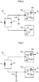
- FIG. 6 and 7 provide further details of possible embodiments along the lines of Figures 2-3 and 4-5 , wherein the I/O PADs of e.g. a microcontroller such as D in Figure 1 may include internal switches S1, S2 (possibly admitting connection to a source Vdd, to ground GND and "open", e.g. floating) as well as Schmitt triggers 141, 142.
- the I/O PADs of e.g. a microcontroller such as D in Figure 1 may include internal switches S1, S2 (possibly admitting connection to a source Vdd, to ground GND and "open", e.g. floating) as well as Schmitt triggers 141, 142.
- circuit diagrams of Figures 6 and 7 are exemplary of arrangements providing good power efficiency by resorting to "clock-less" operation where the excitation time may be controlled by the PAD's via Schmitt triggers and the capacitors Cs and C ref , thus dispensing with high frequency clock sources, with the measurement process adapted to be driven e.g. by a low speed RTC clock (e.g. LSE) that has the basic task of triggering new measurements.
- a low speed RTC clock e.g. LSE
- circuit diagrams of Figures 6 and 7 are exemplary of two implementation schemes:
- a direct charge mechanism may permit to use a smaller C ref with respect to a charge-sharing scheme.
- the senor 10 will be charged by means of a controlled transfer of charge from C ref .
- C ref may be selected with a capacity large enough to store an adequate amount of charge for exciting the sensor 10 and to hold a residual energy in the capacitor (Vmid voltage).
- One or more embodiments as exemplified in Figure 6 may involve two different charge steps: in the former C ref is fully loaded at Vdd and in the latter the accumulated energy is transferred to the sensor 10.
- operation of an arrangement as exemplified in Figure 6 may involve the following steps performed to complete a measurement stage:
- a single sensor 10 may be set between two PADs 101 and 102: in one or more embodiments, that configuration may be extended to cover multiple sensors 10 both in 4 PAD or 6 PAD configurations).
- the PAD 101 may have two main tasks:
- the PAD 102 may have the following main tasks:
- operation of an arrangement as exemplified in Figure 7 may involve the following steps performed to complete a measurement stage:
- the final part of the smooth oscillation may cross the trigger threshold (Vth) with a reduced slope, which may expose the device at the noise: some extra pulse can be generated if a noise with a sufficient amplitude occurs near the Vth crossing.
- noise immunity may be pursued by reducing the time over which the smooth oscillation is near the Vth threshold.
- that result may be achieved by moving the detection phase near the first phase of the oscillation where the slope of the waveform is sharpest and/or by moving dynamically the Vmid voltage during the measurement time.
- the first solution may be applied by reducing the Vmid voltage value.
- a clock-less charge-sharing solution as exemplified in Figure 6 one may activate the PD on the PAD 102 to decrease the Vmid voltage during the oscillation.
- a register may be used to select how many pulses are counted before the PD is enabled, and a register may be similarly used to enable the dynamic PD feature.
- the I02/ZI feedback can be "stretched" to reduce the Vmid voltage with a programmable delay (e.g. a register).
Landscapes
- Physics & Mathematics (AREA)
- General Physics & Mathematics (AREA)
- Electronic Switches (AREA)
- Measurement Of Resistance Or Impedance (AREA)
- Semiconductor Integrated Circuits (AREA)
Claims (8)
- Verfahren zum Betreiben von LC-Sensoren (10), umfassend:- Speichern von Anregungsenergie für einen LC-Sensor (10), und- wobei der LC-Sensor (10) gespeist durch gespeicherte Energie schwingt,wobei das Verfahren umfasst:- Erkennen (12), dass die gespeicherte Energie eine Ladungsschwelle erreicht, und- Beenden des Speicherns von Anregungsenergie für den Sensor (10), wenn erkannt wird (12), dass die Ladungsschwelle erreicht wird,wobei das Verfahren dadurch gekennzeichnet ist, dass es ein Koppeln eines Referenzkondensators (Cref) in Reihe mit dem LC-Sensor (10) umfasst, und- a) Speichern von Anregungsenergie für den Sensor (10) durch Koppeln (S1) der Reihenkopplung des Sensors (10) und des Referenzkondensators (Cref) mit einer Energiequelle (V), oder- b) Beginnen mit dem Speichern von Anregungsenergie für den Sensor (10) durch Koppeln (S1) des Sensors (10) mit einer Energiequelle (V), wobei der Referenzkondensator (Cref) kurzgeschlossen wird (S2), und Entfernen des Kurzschlusses über den Referenzkondensator (Cref), während der LC-Sensor (10) mit der Energiequelle (V) gekoppelt gehalten wird.
- Verfahren nach Anspruch 1, umfassend ein Erkennen (12), dass die gespeicherte Energie eine Ladungsschwelle erreicht, durch Erkennen, dass die Spannung über den Referenzkondensator (Cref) eine Spannungsschwelle erreicht.
- Verfahren nach Anspruch 1 oder 2, umfassend einen Rücksetzschritt, wobei ein Nullspannungsabfall über den LC-Sensor (10) angewendet wird (S1, S2).
- LC-Sensorgerät, umfassend:- Energiespeichermittel zum Speichern von Anregungsenergie,- einen LC-Sensor (10), der so ausgelegt ist, dass er gespeist durch gespeicherte Energie schwingt,wobei das Gerät umfasst:- einen Energiedetektor (12) zum Erkennen, dass die gespeicherte Energie im Energiespeichermittel eine Ladungsschwelle erreicht, und- mindestens einen Schalter (S1, S2), der mit dem Energiedetektor (12) gekoppelt ist, zum Beenden des Speicherns von Anregungsenergie für den Sensor (10) im Energiespeichermittel, wenn durch den Energiedetektor (12) bestimmt wird, dass die Ladungsschwelle erreicht wird,wobei das Gerät dadurch gekennzeichnet ist, dass es umfasst:- einen Referenzkondensator (Cref) in Reihe mit dem LC-Sensor (10) zum Speichern von Anregungsenergie für den Sensor (10), und- eine Energiequelle (V), wobei- a) die Reihenkopplung des Sensors (10) und des Referenzkondensators (Cref) mit der Energiequelle (V) gekoppelt ist, oder- b) der mindestens eine Schalter einen ersten und einen zweiten Schalter umfasst, wobei der erste Schalter (S1) den Sensor (10) mit der Energiequelle (Vdd) koppelt (S1) , wobei der Referenzkondensator (Cref) durch den zweiten Schalter (S2) kurzgeschlossen wird, wobei der zweite Schalter (S2) zum Entfernen des Kurzschlusses über den Referenzkondensator (Cref) geschaltet werden kann, wobei der LC-Sensor (10) durch den ersten Schalter (S1) mit der Energiequelle (Vdd) gekoppelt ist.
- LC-Sensorgerät nach Anspruch 4, wobei der Energiedetektor (12) so ausgelegt ist, dass er durch Erkennen, dass die Spannung über den Referenzkondensator (Cref) eine Spannungsschwelle erreicht, erkennt, dass die gespeicherte Energie eine Ladungsschwelle erreicht.
- LC-Sensorgerät nach einem der Ansprüche 4 oder 5, umfassend Schaltermittel (S1, S2) zum selektiven Anwenden eines Nullspannungsabfalls über den LC-Sensor (10).
- LC-Sensorgerät nach einem der Ansprüche 4 bis 6, umfassend eine Steuereinheit (D), die mindestens eines bereitstellt von:- dem mindestens einen Schalter (S1, S2), der mit dem Energiedetektor (12) gekoppelt ist, zum Beenden des Speicherns von Anregungsenergie für den Sensor (10) im Energiespeichermittel, wenn durch den Energiedetektor (12) bestimmt wird, dass die Ladungsschwelle erreicht wird, und/oder- Erfassungsmittel (141, 142) zum Erfassen der Schwingung des LC-Sensors (10), der gespeist durch gespeicherte Energie schwingt.
- Vorrichtung, vorzugsweise ein Fluidströmungserfassungsgerät, umfassend ein Gerät nach einem der Ansprüche 4 bis 7.
Applications Claiming Priority (1)
| Application Number | Priority Date | Filing Date | Title |
|---|---|---|---|
| ITUB2015A003537A ITUB20153537A1 (it) | 2015-09-10 | 2015-09-10 | Procedimento di funzionamento di sensori lc, sistema ed apparecchiatura corrispondenti |
Publications (2)
| Publication Number | Publication Date |
|---|---|
| EP3141871A1 EP3141871A1 (de) | 2017-03-15 |
| EP3141871B1 true EP3141871B1 (de) | 2020-04-29 |
Family
ID=54601960
Family Applications (1)
| Application Number | Title | Priority Date | Filing Date |
|---|---|---|---|
| EP16162411.9A Active EP3141871B1 (de) | 2015-09-10 | 2016-03-24 | Verfahren für den betrieb von lc-sensoren, entsprechendes system und vorrichtung |
Country Status (3)
| Country | Link |
|---|---|
| US (2) | US10120006B2 (de) |
| EP (1) | EP3141871B1 (de) |
| IT (1) | ITUB20153537A1 (de) |
Families Citing this family (2)
| Publication number | Priority date | Publication date | Assignee | Title |
|---|---|---|---|---|
| US11961665B2 (en) | 2018-11-22 | 2024-04-16 | Behr-Hella Thermocontrol Gmbh | Method and device for controlling an armature solenoid |
| DE102020100939A1 (de) * | 2020-01-16 | 2021-07-22 | Turck Holding Gmbh | Näherungsschalter und Verfahren zur Detektion eines zu erfassenden Objektes |
Family Cites Families (13)
| Publication number | Priority date | Publication date | Assignee | Title |
|---|---|---|---|---|
| US4001718A (en) * | 1975-05-12 | 1977-01-04 | Electro Corporation | Linear oscillator for proximity sensor |
| US4618835A (en) * | 1984-11-27 | 1986-10-21 | Maranantha Research Ltd. | Proximity sensor oscillator utilizing controlled charge |
| US4851770A (en) * | 1985-02-11 | 1989-07-25 | Sensor Technologies, Inc. | Displacement sensor having dual tank circuits |
| FR2614432B1 (fr) * | 1987-04-23 | 1989-07-28 | Telemecanique Electrique | Detecteur de proximite inductif |
| DE4325406B4 (de) * | 1992-09-02 | 2006-02-23 | Tiefenbach Gmbh | Näherungsschalter |
| US5576628A (en) * | 1994-09-30 | 1996-11-19 | Telcom Semiconductor, Inc. | Method and apparatus to measure capacitance |
| DE10130572B4 (de) * | 2001-06-27 | 2010-01-07 | Ifm Electronic Gmbh | Induktiver Wegsensor zur Bestimmung der Position eines Beeinflussungselements und Verfahren zur Bestimmung der Position eines Beeinflussungselements mit einem induktiven Wegsensor |
| US6646454B2 (en) * | 2002-01-07 | 2003-11-11 | Test-Um, Inc. | Electronic apparatus and method for measuring length of a communication cable |
| US7528597B2 (en) * | 2004-03-08 | 2009-05-05 | Digisensors, Inc. | Induction sensor |
| PT1580889E (pt) * | 2004-03-26 | 2008-03-17 | Senstronic S A | Sensor de proximidade indutivo |
| DE102004039401A1 (de) * | 2004-08-13 | 2006-03-09 | Siemens Ag | Transceiver-Transponder-System |
| US7511476B2 (en) * | 2005-01-04 | 2009-03-31 | Digisensors, Inc. | Electromagnetic sensor systems and methods of use thereof |
| DE102007003374A1 (de) * | 2006-02-22 | 2007-09-20 | Pepperl + Fuchs Gmbh | Induktiver Näherungsschalter sowie Verfahren zum Betreiben eines solchen |
-
2015
- 2015-09-10 IT ITUB2015A003537A patent/ITUB20153537A1/it unknown
-
2016
- 2016-03-15 US US15/070,509 patent/US10120006B2/en active Active
- 2016-03-24 EP EP16162411.9A patent/EP3141871B1/de active Active
-
2018
- 2018-09-19 US US16/136,121 patent/US10859617B2/en active Active
Non-Patent Citations (1)
| Title |
|---|
| None * |
Also Published As
| Publication number | Publication date |
|---|---|
| US20190018051A1 (en) | 2019-01-17 |
| US10120006B2 (en) | 2018-11-06 |
| US10859617B2 (en) | 2020-12-08 |
| US20170074914A1 (en) | 2017-03-16 |
| ITUB20153537A1 (it) | 2017-03-10 |
| EP3141871A1 (de) | 2017-03-15 |
Similar Documents
| Publication | Publication Date | Title |
|---|---|---|
| US10852451B2 (en) | System for interfacing an LC sensor, related method and computer program product | |
| EP1382938B1 (de) | Positionsdetektor | |
| US7586303B2 (en) | Inductive proximity sensor | |
| US20130093436A1 (en) | Electromagnetic method for sensing the relative position of two items using coupled tuned circuits | |
| JP6228543B2 (ja) | 漏れ電流の存在下でイオン電流を判定するための差動電流測定 | |
| US10859617B2 (en) | Method of operating LC sensors, corresponding system and apparatus | |
| CN107229277A (zh) | 一种悬崖检测电路及其扫地机器人 | |
| US7574924B1 (en) | Magnetic flow meter | |
| US10756732B2 (en) | Inductive sensor and method for operating an inductive sensor | |
| US11588353B2 (en) | Quality factor estimation of an inductive element | |
| US9038480B2 (en) | Integrated circuit and apparatus for detecting oscillations | |
| US20080084203A1 (en) | Pulsed coil drive circuit for a sampled inductive transducer | |
| CN105319599B (zh) | 对接lc传感器的方法及其系统 | |
| CN106093457B (zh) | 转速传感器 | |
| JP2002527718A5 (de) | ||
| KR100370484B1 (ko) | 금속물체의 검출장치 | |
| JP2000321248A (ja) | オイルチェックセンサ | |
| JP2003329404A (ja) | 液圧流量制御弁における位置検出器 | |
| JP2003328846A (ja) | ディーゼルエンジン用溢流式燃料噴射ポンプ装置における燃料噴射量検出器 | |
| CN101187543A (zh) | 用于采样电感式换能器的脉冲线圈驱动电路 |
Legal Events
| Date | Code | Title | Description |
|---|---|---|---|
| PUAI | Public reference made under article 153(3) epc to a published international application that has entered the european phase |
Free format text: ORIGINAL CODE: 0009012 |
|
| STAA | Information on the status of an ep patent application or granted ep patent |
Free format text: STATUS: THE APPLICATION HAS BEEN PUBLISHED |
|
| AK | Designated contracting states |
Kind code of ref document: A1 Designated state(s): AL AT BE BG CH CY CZ DE DK EE ES FI FR GB GR HR HU IE IS IT LI LT LU LV MC MK MT NL NO PL PT RO RS SE SI SK SM TR |
|
| AX | Request for extension of the european patent |
Extension state: BA ME |
|
| STAA | Information on the status of an ep patent application or granted ep patent |
Free format text: STATUS: REQUEST FOR EXAMINATION WAS MADE |
|
| 17P | Request for examination filed |
Effective date: 20170906 |
|
| RBV | Designated contracting states (corrected) |
Designated state(s): AL AT BE BG CH CY CZ DE DK EE ES FI FR GB GR HR HU IE IS IT LI LT LU LV MC MK MT NL NO PL PT RO RS SE SI SK SM TR |
|
| GRAP | Despatch of communication of intention to grant a patent |
Free format text: ORIGINAL CODE: EPIDOSNIGR1 |
|
| STAA | Information on the status of an ep patent application or granted ep patent |
Free format text: STATUS: GRANT OF PATENT IS INTENDED |
|
| INTG | Intention to grant announced |
Effective date: 20191120 |
|
| GRAS | Grant fee paid |
Free format text: ORIGINAL CODE: EPIDOSNIGR3 |
|
| GRAA | (expected) grant |
Free format text: ORIGINAL CODE: 0009210 |
|
| STAA | Information on the status of an ep patent application or granted ep patent |
Free format text: STATUS: THE PATENT HAS BEEN GRANTED |
|
| AK | Designated contracting states |
Kind code of ref document: B1 Designated state(s): AL AT BE BG CH CY CZ DE DK EE ES FI FR GB GR HR HU IE IS IT LI LT LU LV MC MK MT NL NO PL PT RO RS SE SI SK SM TR |
|
| REG | Reference to a national code |
Ref country code: GB Ref legal event code: FG4D |
|
| REG | Reference to a national code |
Ref country code: CH Ref legal event code: EP |
|
| REG | Reference to a national code |
Ref country code: DE Ref legal event code: R096 Ref document number: 602016034904 Country of ref document: DE |
|
| REG | Reference to a national code |
Ref country code: AT Ref legal event code: REF Ref document number: 1263990 Country of ref document: AT Kind code of ref document: T Effective date: 20200515 |
|
| REG | Reference to a national code |
Ref country code: IE Ref legal event code: FG4D |
|
| REG | Reference to a national code |
Ref country code: NL Ref legal event code: MP Effective date: 20200429 |
|
| REG | Reference to a national code |
Ref country code: LT Ref legal event code: MG4D |
|
| PG25 | Lapsed in a contracting state [announced via postgrant information from national office to epo] |
Ref country code: GR Free format text: LAPSE BECAUSE OF FAILURE TO SUBMIT A TRANSLATION OF THE DESCRIPTION OR TO PAY THE FEE WITHIN THE PRESCRIBED TIME-LIMIT Effective date: 20200730 Ref country code: LT Free format text: LAPSE BECAUSE OF FAILURE TO SUBMIT A TRANSLATION OF THE DESCRIPTION OR TO PAY THE FEE WITHIN THE PRESCRIBED TIME-LIMIT Effective date: 20200429 Ref country code: NO Free format text: LAPSE BECAUSE OF FAILURE TO SUBMIT A TRANSLATION OF THE DESCRIPTION OR TO PAY THE FEE WITHIN THE PRESCRIBED TIME-LIMIT Effective date: 20200729 Ref country code: IS Free format text: LAPSE BECAUSE OF FAILURE TO SUBMIT A TRANSLATION OF THE DESCRIPTION OR TO PAY THE FEE WITHIN THE PRESCRIBED TIME-LIMIT Effective date: 20200829 Ref country code: SE Free format text: LAPSE BECAUSE OF FAILURE TO SUBMIT A TRANSLATION OF THE DESCRIPTION OR TO PAY THE FEE WITHIN THE PRESCRIBED TIME-LIMIT Effective date: 20200429 Ref country code: PT Free format text: LAPSE BECAUSE OF FAILURE TO SUBMIT A TRANSLATION OF THE DESCRIPTION OR TO PAY THE FEE WITHIN THE PRESCRIBED TIME-LIMIT Effective date: 20200831 Ref country code: FI Free format text: LAPSE BECAUSE OF FAILURE TO SUBMIT A TRANSLATION OF THE DESCRIPTION OR TO PAY THE FEE WITHIN THE PRESCRIBED TIME-LIMIT Effective date: 20200429 |
|
| REG | Reference to a national code |
Ref country code: AT Ref legal event code: MK05 Ref document number: 1263990 Country of ref document: AT Kind code of ref document: T Effective date: 20200429 |
|
| PG25 | Lapsed in a contracting state [announced via postgrant information from national office to epo] |
Ref country code: RS Free format text: LAPSE BECAUSE OF FAILURE TO SUBMIT A TRANSLATION OF THE DESCRIPTION OR TO PAY THE FEE WITHIN THE PRESCRIBED TIME-LIMIT Effective date: 20200429 Ref country code: HR Free format text: LAPSE BECAUSE OF FAILURE TO SUBMIT A TRANSLATION OF THE DESCRIPTION OR TO PAY THE FEE WITHIN THE PRESCRIBED TIME-LIMIT Effective date: 20200429 Ref country code: BG Free format text: LAPSE BECAUSE OF FAILURE TO SUBMIT A TRANSLATION OF THE DESCRIPTION OR TO PAY THE FEE WITHIN THE PRESCRIBED TIME-LIMIT Effective date: 20200729 Ref country code: LV Free format text: LAPSE BECAUSE OF FAILURE TO SUBMIT A TRANSLATION OF THE DESCRIPTION OR TO PAY THE FEE WITHIN THE PRESCRIBED TIME-LIMIT Effective date: 20200429 |
|
| PG25 | Lapsed in a contracting state [announced via postgrant information from national office to epo] |
Ref country code: AL Free format text: LAPSE BECAUSE OF FAILURE TO SUBMIT A TRANSLATION OF THE DESCRIPTION OR TO PAY THE FEE WITHIN THE PRESCRIBED TIME-LIMIT Effective date: 20200429 Ref country code: NL Free format text: LAPSE BECAUSE OF FAILURE TO SUBMIT A TRANSLATION OF THE DESCRIPTION OR TO PAY THE FEE WITHIN THE PRESCRIBED TIME-LIMIT Effective date: 20200429 |
|
| PG25 | Lapsed in a contracting state [announced via postgrant information from national office to epo] |
Ref country code: SM Free format text: LAPSE BECAUSE OF FAILURE TO SUBMIT A TRANSLATION OF THE DESCRIPTION OR TO PAY THE FEE WITHIN THE PRESCRIBED TIME-LIMIT Effective date: 20200429 Ref country code: EE Free format text: LAPSE BECAUSE OF FAILURE TO SUBMIT A TRANSLATION OF THE DESCRIPTION OR TO PAY THE FEE WITHIN THE PRESCRIBED TIME-LIMIT Effective date: 20200429 Ref country code: RO Free format text: LAPSE BECAUSE OF FAILURE TO SUBMIT A TRANSLATION OF THE DESCRIPTION OR TO PAY THE FEE WITHIN THE PRESCRIBED TIME-LIMIT Effective date: 20200429 Ref country code: CZ Free format text: LAPSE BECAUSE OF FAILURE TO SUBMIT A TRANSLATION OF THE DESCRIPTION OR TO PAY THE FEE WITHIN THE PRESCRIBED TIME-LIMIT Effective date: 20200429 Ref country code: ES Free format text: LAPSE BECAUSE OF FAILURE TO SUBMIT A TRANSLATION OF THE DESCRIPTION OR TO PAY THE FEE WITHIN THE PRESCRIBED TIME-LIMIT Effective date: 20200429 Ref country code: AT Free format text: LAPSE BECAUSE OF FAILURE TO SUBMIT A TRANSLATION OF THE DESCRIPTION OR TO PAY THE FEE WITHIN THE PRESCRIBED TIME-LIMIT Effective date: 20200429 Ref country code: IT Free format text: LAPSE BECAUSE OF FAILURE TO SUBMIT A TRANSLATION OF THE DESCRIPTION OR TO PAY THE FEE WITHIN THE PRESCRIBED TIME-LIMIT Effective date: 20200429 Ref country code: DK Free format text: LAPSE BECAUSE OF FAILURE TO SUBMIT A TRANSLATION OF THE DESCRIPTION OR TO PAY THE FEE WITHIN THE PRESCRIBED TIME-LIMIT Effective date: 20200429 |
|
| REG | Reference to a national code |
Ref country code: DE Ref legal event code: R097 Ref document number: 602016034904 Country of ref document: DE |
|
| PG25 | Lapsed in a contracting state [announced via postgrant information from national office to epo] |
Ref country code: PL Free format text: LAPSE BECAUSE OF FAILURE TO SUBMIT A TRANSLATION OF THE DESCRIPTION OR TO PAY THE FEE WITHIN THE PRESCRIBED TIME-LIMIT Effective date: 20200429 Ref country code: SK Free format text: LAPSE BECAUSE OF FAILURE TO SUBMIT A TRANSLATION OF THE DESCRIPTION OR TO PAY THE FEE WITHIN THE PRESCRIBED TIME-LIMIT Effective date: 20200429 |
|
| PLBE | No opposition filed within time limit |
Free format text: ORIGINAL CODE: 0009261 |
|
| STAA | Information on the status of an ep patent application or granted ep patent |
Free format text: STATUS: NO OPPOSITION FILED WITHIN TIME LIMIT |
|
| 26N | No opposition filed |
Effective date: 20210201 |
|
| PG25 | Lapsed in a contracting state [announced via postgrant information from national office to epo] |
Ref country code: SI Free format text: LAPSE BECAUSE OF FAILURE TO SUBMIT A TRANSLATION OF THE DESCRIPTION OR TO PAY THE FEE WITHIN THE PRESCRIBED TIME-LIMIT Effective date: 20200429 |
|
| PG25 | Lapsed in a contracting state [announced via postgrant information from national office to epo] |
Ref country code: MC Free format text: LAPSE BECAUSE OF FAILURE TO SUBMIT A TRANSLATION OF THE DESCRIPTION OR TO PAY THE FEE WITHIN THE PRESCRIBED TIME-LIMIT Effective date: 20200429 |
|
| REG | Reference to a national code |
Ref country code: CH Ref legal event code: PL |
|
| GBPC | Gb: european patent ceased through non-payment of renewal fee |
Effective date: 20210324 |
|
| REG | Reference to a national code |
Ref country code: BE Ref legal event code: MM Effective date: 20210331 |
|
| PG25 | Lapsed in a contracting state [announced via postgrant information from national office to epo] |
Ref country code: CH Free format text: LAPSE BECAUSE OF NON-PAYMENT OF DUE FEES Effective date: 20210331 Ref country code: LU Free format text: LAPSE BECAUSE OF NON-PAYMENT OF DUE FEES Effective date: 20210324 Ref country code: LI Free format text: LAPSE BECAUSE OF NON-PAYMENT OF DUE FEES Effective date: 20210331 Ref country code: FR Free format text: LAPSE BECAUSE OF NON-PAYMENT OF DUE FEES Effective date: 20210331 Ref country code: IE Free format text: LAPSE BECAUSE OF NON-PAYMENT OF DUE FEES Effective date: 20210324 Ref country code: GB Free format text: LAPSE BECAUSE OF NON-PAYMENT OF DUE FEES Effective date: 20210324 |
|
| PG25 | Lapsed in a contracting state [announced via postgrant information from national office to epo] |
Ref country code: BE Free format text: LAPSE BECAUSE OF NON-PAYMENT OF DUE FEES Effective date: 20210331 |
|
| PG25 | Lapsed in a contracting state [announced via postgrant information from national office to epo] |
Ref country code: HU Free format text: LAPSE BECAUSE OF FAILURE TO SUBMIT A TRANSLATION OF THE DESCRIPTION OR TO PAY THE FEE WITHIN THE PRESCRIBED TIME-LIMIT; INVALID AB INITIO Effective date: 20160324 |
|
| PG25 | Lapsed in a contracting state [announced via postgrant information from national office to epo] |
Ref country code: CY Free format text: LAPSE BECAUSE OF FAILURE TO SUBMIT A TRANSLATION OF THE DESCRIPTION OR TO PAY THE FEE WITHIN THE PRESCRIBED TIME-LIMIT Effective date: 20200429 |
|
| PG25 | Lapsed in a contracting state [announced via postgrant information from national office to epo] |
Ref country code: MK Free format text: LAPSE BECAUSE OF FAILURE TO SUBMIT A TRANSLATION OF THE DESCRIPTION OR TO PAY THE FEE WITHIN THE PRESCRIBED TIME-LIMIT Effective date: 20200429 |
|
| PG25 | Lapsed in a contracting state [announced via postgrant information from national office to epo] |
Ref country code: MT Free format text: LAPSE BECAUSE OF FAILURE TO SUBMIT A TRANSLATION OF THE DESCRIPTION OR TO PAY THE FEE WITHIN THE PRESCRIBED TIME-LIMIT Effective date: 20200429 |
|
| PGFP | Annual fee paid to national office [announced via postgrant information from national office to epo] |
Ref country code: DE Payment date: 20250218 Year of fee payment: 10 |
|
| PG25 | Lapsed in a contracting state [announced via postgrant information from national office to epo] |
Ref country code: TR Free format text: LAPSE BECAUSE OF FAILURE TO SUBMIT A TRANSLATION OF THE DESCRIPTION OR TO PAY THE FEE WITHIN THE PRESCRIBED TIME-LIMIT Effective date: 20200429 |