EP1580555A1 - Magnetische teilchen aufsammelnder körper mit magnetkraft und seine verwendung - Google Patents
Magnetische teilchen aufsammelnder körper mit magnetkraft und seine verwendung Download PDFInfo
- Publication number
- EP1580555A1 EP1580555A1 EP03810654A EP03810654A EP1580555A1 EP 1580555 A1 EP1580555 A1 EP 1580555A1 EP 03810654 A EP03810654 A EP 03810654A EP 03810654 A EP03810654 A EP 03810654A EP 1580555 A1 EP1580555 A1 EP 1580555A1
- Authority
- EP
- European Patent Office
- Prior art keywords
- magnetic
- magnetic material
- magnetic particles
- liquid
- reaction
- Prior art date
- Legal status (The legal status is an assumption and is not a legal conclusion. Google has not performed a legal analysis and makes no representation as to the accuracy of the status listed.)
- Granted
Links
Images


Classifications
-
- G—PHYSICS
- G01—MEASURING; TESTING
- G01N—INVESTIGATING OR ANALYSING MATERIALS BY DETERMINING THEIR CHEMICAL OR PHYSICAL PROPERTIES
- G01N35/00—Automatic analysis not limited to methods or materials provided for in any single one of groups G01N1/00 - G01N33/00; Handling materials therefor
- G01N35/0098—Automatic analysis not limited to methods or materials provided for in any single one of groups G01N1/00 - G01N33/00; Handling materials therefor involving analyte bound to insoluble magnetic carrier, e.g. using magnetic separation
-
- B—PERFORMING OPERATIONS; TRANSPORTING
- B03—SEPARATION OF SOLID MATERIALS USING LIQUIDS OR USING PNEUMATIC TABLES OR JIGS; MAGNETIC OR ELECTROSTATIC SEPARATION OF SOLID MATERIALS FROM SOLID MATERIALS OR FLUIDS; SEPARATION BY HIGH-VOLTAGE ELECTRIC FIELDS
- B03C—MAGNETIC OR ELECTROSTATIC SEPARATION OF SOLID MATERIALS FROM SOLID MATERIALS OR FLUIDS; SEPARATION BY HIGH-VOLTAGE ELECTRIC FIELDS
- B03C1/00—Magnetic separation
- B03C1/02—Magnetic separation acting directly on the substance being separated
- B03C1/28—Magnetic plugs and dipsticks
- B03C1/288—Magnetic plugs and dipsticks disposed at the outer circumference of a recipient
-
- G—PHYSICS
- G01—MEASURING; TESTING
- G01N—INVESTIGATING OR ANALYSING MATERIALS BY DETERMINING THEIR CHEMICAL OR PHYSICAL PROPERTIES
- G01N1/00—Sampling; Preparing specimens for investigation
- G01N1/28—Preparing specimens for investigation including physical details of (bio-)chemical methods covered elsewhere, e.g. G01N33/50, C12Q
- G01N1/40—Concentrating samples
- G01N1/405—Concentrating samples by adsorption or absorption
-
- G—PHYSICS
- G01—MEASURING; TESTING
- G01N—INVESTIGATING OR ANALYSING MATERIALS BY DETERMINING THEIR CHEMICAL OR PHYSICAL PROPERTIES
- G01N33/00—Investigating or analysing materials by specific methods not covered by groups G01N1/00 - G01N31/00
- G01N33/48—Biological material, e.g. blood, urine; Haemocytometers
- G01N33/50—Chemical analysis of biological material, e.g. blood, urine; Testing involving biospecific ligand binding methods; Immunological testing
- G01N33/53—Immunoassay; Biospecific binding assay; Materials therefor
- G01N33/543—Immunoassay; Biospecific binding assay; Materials therefor with an insoluble carrier for immobilising immunochemicals
- G01N33/551—Immunoassay; Biospecific binding assay; Materials therefor with an insoluble carrier for immobilising immunochemicals the carrier being inorganic
- G01N33/553—Metal or metal coated
-
- B—PERFORMING OPERATIONS; TRANSPORTING
- B03—SEPARATION OF SOLID MATERIALS USING LIQUIDS OR USING PNEUMATIC TABLES OR JIGS; MAGNETIC OR ELECTROSTATIC SEPARATION OF SOLID MATERIALS FROM SOLID MATERIALS OR FLUIDS; SEPARATION BY HIGH-VOLTAGE ELECTRIC FIELDS
- B03C—MAGNETIC OR ELECTROSTATIC SEPARATION OF SOLID MATERIALS FROM SOLID MATERIALS OR FLUIDS; SEPARATION BY HIGH-VOLTAGE ELECTRIC FIELDS
- B03C2201/00—Details of magnetic or electrostatic separation
- B03C2201/26—Details of magnetic or electrostatic separation for use in medical or biological applications
Definitions
- the present invention relates to a magnetic material for collecting magnetic particles, a method of collecting magnetic particles using the magnetic material, and an apparatus for using the magnetic material.
- the present invention can be used in analyses using magnetic particles, such as an immunoassay.
- B/F separation means a step of separating an antigen-antibody reaction product from an unreacted substance by discarding the reaction mixture containing the unreacted substance from a reaction vessel such as a reaction tube or wells of a microtiter plate and repeating a washing operation that includes supplying and discarding a washing solution.
- the magnetic particles and a sample are mixed to perform an antigen-antibody reaction, and then B/F separation including a step of collecting the magnetic particles that contain the generated immune complex and a step of separating and washing unreacted antigen or antibody can be performed easily and quickly using magnetic force.
- a method that involves contacting the magnetic material with a reaction vessel or the like that is in a state of stand still, such as a reaction tube or wells of a microtiter plate, and collecting magnetic particles see, for example, JP 3-144367 A
- a method which involves collecting magnetic particles by contacting a magnetic material with a tip, a stainless steel pipe, or a flexible tube used as a flow line for sucking/discharging liquid from/into a vessel see, for example, JP 3115501 B
- many other reports have been made.
- the micro-magnetic particles are useful for performing various reactions at a high efficiency, they tend to float in the solution, which tends to lead to a reduced recovery rate.
- the recovery rate decreases, the magnetic particles may flow outward in the processes of washing, separation and so on to cause an error. This may reduce the reliability of measured values.
- the washing is insufficient with a view to preventing the magnetic particles from flowing outward, complete separation cannot be attained.
- samples after separation for example, pretreated samples are used, contamination may occur.
- the B/F separation is performed a plurality of times and if the outward flow of the magnetic particles or errors occur, the measured values are greatly influenced.
- the present invention has been made to provide a magnetic material for collecting magnetic particles that collects the magnetic particles with ease and at a high efficiency, a method of collecting magnetic particles using the magnetic material, and an apparatus having provided therewith the magnetic material.
- the inventors of the present invention have made extensive study to achieve the above-mentioned problems. As a result, the inventors have found that a magnetic material capable of collecting magnetic particles efficiently can be produced by assembling a plurality of magnets in parallel to the direction of magnetization in such a manner that the south and north poles of adjacent magnets alternately reversed. The present invention has been accomplished based on these findings.
- Magnetic material for collecting magnetic particles according to the present invention
- the magnetic material for collecting magnetic particles according to the present invention includes a plurality of magnets arranged in such a manner that adjacent magnets contact each other.
- the magnets in the magnetic material of the present invention has such a feature that they are arranged in parallel to the direction of magnetization in such a manner that the south and north poles of the adjacent magnetic poles are reversed alternately (hereinafter, this being also referred to as "layered").
- the term “parallel” does not mean that the direction of magnetization of each magnet constituting the magnetic material is the same.
- the term “parallel” also includes the case in which the direction of magnetization of one magnet is opposite to the direction of magnetization of another magnet.
- the magnetic force of a magnet is strong at the end portion of a side from which the magnet generates magnetic force (a side vertical to the direction of magnetization of the magnet constituting the magnetic material: hereinafter, this being also referred to as a "magnetic pole surface"), and weak in the central portion of the side. Therefore, when, for example, a magnetic material composed of a single magnet (hereinafter, this being also referred to as a “single magnet-magnetic material”) is used, a strong magnetic force is obtained only at the end portion of the magnetic material even if a large magnet is used. Strong magnetic force therefore cannot be obtained over the entire pole surface of the magnet. This makes collection of the magnetic particles inefficient.
- a plurality of magnets are arranged in parallel to the direction of magnetization in such a manner that the south and north poles of adjacent magnets are reversed alternately.
- strong magnetic force can be obtained at the sites where the magnets contact each other in the magnetic material (hereinafter, this being also referred to as "layered portion") and the magnetic force is weak in the central portion of each magnet. That is, in the single magnet-magnetic material, a strong magnetic force can be obtained only at the end portion of the magnet in a pole surface having a certain fixed area.
- the magnetic material of the present invention has such a feature that strong magnetic force is obtained at a plurality of sites of the pole surface of the magnetic material since a plurality of the magnets are layered to constitute the magnetic material.
- the magnetic material of the present invention has at least one peak of magnetic force in the pole surface. "Having a peak” means that the magnetic force at a point in the magnetic pole surface is greater than the magnetic forces at points on both sides of the above-mentioned point in the cross-sectional direction of the magnets, with this point being called a "peak".
- the single magnet-magnetic material has sites where strong magnets are obtained only on both ends of the magnetic pole surface.
- strong magnetic forces are obtained (the magnetic material has peaks) at one layered portion as well as at the both ends.
- the magnetic material having layered three magnets strong magnetic forces are obtained (the magnetic material has peaks) at two layered portions as well as at the both ends.
- the magnetic material of the present invention includes a plurality of magnets combined with each other, so each magnet can have an appropriately small size. This makes the distance in which the magnet lines reach short and the magnet lines accumulate near the magnetic pole surface, resulting in a decreased stray magnetic field. Therefore, for example, when the magnetic material of the present invention is used as a magnetic material for collecting magnetic particles and contacted to a liquid suction line having a thin flow path, the magnetic particles can be collected efficiently.
- the magnetic material of the present invention can very efficiently collect magnet particles on the inner wall of the liquid suction line or vessel, and hence is very suitable as a magnetic material for collecting magnetic particles.
- any magnet having an S pole (south pole) and an N pole (north pole) and capable of generating magnetic force that can collect magnetic particles may be used.
- the magnets include permanent magnets and electromagnets. Permanent magnets are preferably used in view of intensity and stability of the generated magnetic field and because no power source is necessary. Examples of the permanent magnet include those obtained by molding suitable magnetic materials, such as Alnico, barium ferrite, neodymium, and samarium cobalt, into any desired shapes, such as rod, plate, cube, disk, and horseshoe arch, and magnetizing the molded magnetic materials.
- the rod-shaped permanent magnet preferably has a rectangular cross-section.
- a neodymium magnet molded into a rod or a plate is preferably used.
- the magnetic material of the present invention can be produced by arranging a plurality of the above-mentioned magnets in contact with each other in parallel to the direction of magnetization in such a manner that the south and north poles of adjacent magnetic poles are reversed alternately. Even when a space is present between the magnets, the magnets are considered to substantially contact with each other as long as the magnetic material is constituted integrally and the desired magnetic force is sufficiently obtained.
- the term "in contact" in the present invention includes the case in which the magnets substantially contact each other in this manner. However, it is preferable that no space is present between the magnets.
- At least two magnets preferably at least three magnets, are used in combination.
- the upper limit of the number of the magnets depends on the size of the magnet used and the designed size (outer size) of the magnetic material of the present invention to be produced from a plurality of the magnets.
- the sizes of the magnets may be the same or different from each other. It is preferable that the magnets have the same size.
- the magnetic force generated is weak and the efficiency of collecting the magnetic particles may decrease.
- the preferable number and size of magnets may be determined by measuring the magnetic force at the site where the magnetic material contacts by the technique explained later, or actually obtaining the recovery rate of the magnetic particles, and confirming that the magnetic force of the magnetic material is sufficient for collecting the magnetic particles.
- the outer size may be determined in view of the size of the reaction vessel or the like to which the magnetic material is contacted and the specification of the apparatus in which the magnetic material is arranged.
- the outer size of the magnetic material must not be too large with respect to the apparatus, and that the portions of the apparatus that are susceptible to the influence of magnetic force, such as photomultipliers, must not be influenced by the magnetic force.
- the outer size of the magnetic material may be determined depending on the length, inner diameter, wall thickness, material and the like of the tips used as the line.
- the length of face (magnetic pole surface) of a single magnet that contacts the line is determined depending on the wall thickness and so on. It is important to use a magnetic material that generates magnetic lines between the adjacent magnets appropriately reach the moving line of the magnetic particles. More particularly, when tips having a wall thickness of 0.75 mm are used, the longitudinal length of a single magnet (longitudinal length of the magnet in the direction of lamination) is preferably 3 mm or more.
- the longitudinal length of the magnet may be determined depending on, for example, the length, inner diameter, wall thickness, and material of the reaction tube, or the size of the microtiter plate and the size of wells thereon.
- disposable tips having an inner diameter of about 2 to 3 mm and a wall thickness of about 0.5 to 1 mm are arranged as a liquid suction line for sucking and discharging a liquid.
- polypropylene-made disposable tips having an inner diameter of 2.25 mm and a wall thickness of 0.75 mm are preferable used.
- the magnetic material for collecting magnetic particles that is used in contact with the liquid suction line as described above has a size of, for example, 50 mm or less, preferably 20 mm or less in longitudinal length (direction of lamination) and 20 mm or less, preferably 15 mm or less in transverse length (direction of magnetization).
- the magnetic material has a width of 10 mm or less, preferably 5 mm or less.
- the lower limits of the size may be any desired size so far as the object of collecting the magnetic particles is achieved.
- the number of magnets to be layered is preferably 2 to 4, particularly preferably 3 when producing a magnetic material having an outer size of, for example, 15 mm in longitudinal length x 14 mm in transversal length x 4 mm in width. That is, the longitudinal length of one magnet is suitably about 3.75 to 7.5 mm.
- each magnet that constitutes the magnetic material of the present invention can be determined reliably, for example, by measuring the magnetic force on the inner wall surface of the liquid suction line, which is a site where the magnetic particles are adsorbed to confirm that the measured magnetic force is sufficient for adsorbing the magnetic particles. Also, a method that involves actually measuring the recovery rate (collection efficiency) of the magnetic particles to confirm that the measured recovery rate is preferably 80% or more, particularly preferably 90% or more is preferably used.
- Examples of the method of measuring the magnetic force on the inner wall surface includes a method of actually measuring the magnetic force exerted on the inner wall surface of the liquid suction line using a commonly used magnetic force measuring apparatus, such as a handy gauss meter (MODEL 4048: manufactured by F. W. BELL). More particularly, for example, a measuring probe (for example, in the case of the above-mentioned measuring apparatus, T-4048-001 (manufactured by F. W. BELL)) is set near the pole surface of the magnetic material and the magnetic force is measured. In this case, the probe is set advantageously at a small distance from the magnetic pole surface taking into consideration that the tip has actually a wall thickness. Also, the magnetic force may be measured, for example, by actually contacting the magnetic material with the outer wall surface of the tip and setting the probe on the inner wall surface to measure the magnetic force on the inner wall surface of the tip.
- a measuring probe for example, in the case of the above-mentioned measuring apparatus, T-4048-001 (manu
- the pole surface of the magnetic material of the present invention has a strong peak at the site where the magnets contact each other (layered portion) and a weak magnetic force in the central portion of each magnet. That is, when the magnetic material of the present invention is produced, it is preferable that an indicator is adopted that a sufficient magnetic force can be obtained not only at the end portions but also at each layered portion.
- the magnetic material of the present invention preferably includes a plurality of layered portions and has a sufficient size for the magnetic force in each layered portion to collect the magnetic particles.
- the term "sufficient magnetic force at each layered portion" means, for example, 600 gausses or more, preferably 800 gausses or more, more preferably 1,000 gausses or more.
- the measurement is performed at a plurality of sites on the magnetic pole surface to confirm that a sufficient magnetic force can be obtained over the plurality of the sites.
- the probe may be set either vertically or in parallel to the magnetic pole surface so far as the measurement is performed according to a predetermined technique and the measured values can be compared.
- the measuring portion of the probe generally has a certain area and it is difficult to measure the magnetic force at a single point.
- the magnetic force at the layered portions is measured. More preferably, continuous measurements are made at a plurality of points including those in the layered portions and the number of peaks of the magnetic force and the intensity of the magnetic force are analyzed.
- the recovery of the magnetic particles can be obtained by actually providing a commercially available magnetic particle dispersion in an automatic measuring apparatus having arranged therein the magnetic material of the present invention and performing experiments in the same manner as the target measuring method.
- the magnetic particles include HTLV-1 magnetic particle reagent Lumipulse HTLV-1 (manufactured by FUJIREBIO, INC.), TP-N magnetic particle reagent Lumipulse II TP-N (manufactured by FUJIREBIO, INC.), and magnetic particle RP-M1 (manufactured by Rohne-Poulenc).
- the method of producing the magnetic material of the present invention by contacting a plurality of magnets in parallel each other may utilize the holding powers of the magnets in binding the magnets to each other since the magnets are adjacently arranged with the south and north magnetic poles being reversed alternately, or may utilize bonding adhesive or the like. As described above, so far as the magnetic material has a sufficient magnetic force, a space may be present between adjacent magnets.
- the method of collecting magnetic particles of the present invention involves adsorbing and holding the magnetic particles in a liquid on the wall surface by the magnetic force and then making the magnetic particles unaffected by the magnetic force to release the magnetic particles and is characterized in that the magnetic force is generated by the above-mentioned magnetic material of the present invention.
- the magnetic material used in the present invention is the above-mentioned magnetic material of the present invention.
- the above-mentioned magnetic material can generate strong magnetic force in the layered portion of the magnets and has a feature that the magnetic lines accumulate near the magnetic material, so the stray magnetic field decreases, and hence the magnetic force is increased in the side (magentic pole surface) vertical to the direction of magnetization of the magnets constituting the magnetic material. Accordingly, the magnetic particles can be collected effectively using the magnetic pole surface.
- wall surface means an inner wall surface and the like of a reaction vessel such as a reaction tube or wells of a microtiter plate, and of the liquid suction line of a dispenser that sucks liquid from a vessel and discharges the liquid.
- the wall surface is the inner wall surface of the above-mentioned liquid suction line.
- the magnetic particles can be simply and easily released from the inner wall surface.
- Conventional technique has a problem that the magnetic particles tend to be lost.
- high recovery rates are achieved, which solves the problem.
- the magnetic material is held off the wall surface when the magnetic material is a permanent magnet and when the magnetic material is an electromagnet, the object is achieved by the same method as described above or by stopping the application of current to the electromagnet in the same manner as described above.
- any magnetic particles may be used so far as the magnetic particles have properties of being collected under the influence of magnetic force generated by the magnetic material.
- the diameter is not limited.
- the shape of the magnetic particles is not limited to spherical and those magnetic particles that have a suitable material, coating, and size depending on the objective measurement, analysis, reaction and so on may be selected and used.
- magnetic particles made of metals such as triiron tetraoxide (Fe 3 O 4 ), diiron trioxide (Fe 2 O 3 ), various types of ferrites, iron, manganese, nickel, cobalt, and chromium, alloys of cobalt, nickel, and manganese are preferably used.
- These magnetic particles may be prepared as included in latex of a polymer such as polystyrene, gelatin, liposomes, or as immobilized on the surface thereof.
- the shape of the magnetic particles is preferably spherical.
- the particle size of the magnetic particles may be any particle size so far as the B/F separation can be performed with a high accuracy using the magnetic material of the present invention.
- the lower limit of the particle size is 0.05 ⁇ m, preferably 0.1 ⁇ m while the upper limit of the particle size is 10 ⁇ m, preferably 4 ⁇ m, more preferably 2 ⁇ m.
- the ranges of the particle size are selected from combinations of the upper and lower limits. Specific example of the particle size is usually from 0.05 to 10 ⁇ m, preferably from 0.05 to 4 ⁇ m, more preferably 0.1 to 2 ⁇ m.
- An antigen or an antibody is carried on the magnetic particles by a method that is commonly used and known per se and the resultant is used in the immunoassay.
- Examples of the method of carrying an antigen or an antibody on the magnetic particles include a physical adsorption method and a chemical binding method.
- the amount of adsorption, the kind of the solution in which the magnetic particles are suspended, the concentration of the magnetic particles in the solution, and so on may be appropriately selected depending on the magnetic particles used, antigen or antibody, target of measurement, sample, and so on.
- magnetic particles as described above and the magnetic particles that carry any antigen or antibody are offered commercially as magnetic particles or reagents and are readily available.
- those magnetic particles used for extracting and analyzing nucleic acids may be any magnetic particles so far as they can be mixed with a solution containing a nucleic acid and subjected to a reaction as necessary to have the nucleic acid attached to the surface thereof.
- the site and method of collecting the magnetic particles may be performed according to the method of collecting the magnetic particles by a magnetic material that is known per se and commonly used.
- the magnetic material is used in such a manner that the side (magnetic pole surface) which is vertical to the direction of magnetization of the magnets constituting the magnetic material of the present invention contacts the outer wall surface of the reactor or the like presented for the target measurement, analysis, and reaction. More particularly, for example, when the magnetic particles are collected in a vessel that is used in a state of stand still, such as a reaction tube or a microtiter plate, the magnetic material of the present invention can be used by contacting the magnetic material with the reaction tube or wells of the microtiter plate at the side or bottom thereof.
- the magnetic material of the present invention can be used by contacting it with the side of the tip, stainless steel pipe, or flexible tube.
- the method of the present invention is used particularly advantageously in an automatic measuring apparatus in which a liquid suction line is arranged.
- the method of the present invention can be applied to various measurements, analyses, reactions and so on that are performed using magnetic particles.
- the substances to be tested, which are targets of measurement include, for example, immunological substances, biological substances, molecular substances, and so on such as antigens, antibodies, proteins, ligands, enzymes, substrates, DNAs, vector DNAs, RNAs, and plasmids.
- immunological substances such as antigens, antibodies, proteins, ligands, enzymes, substrates, DNAs, vector DNAs, RNAs, and plasmids.
- various kinds of labeled substances used for isotopes, enzymes, chemiluminescence, fluorescence, electrochemiluminescence, and so on are employed.
- the measuring method and apparatus that can be used may be those known per se and commonly used.
- the method of the present invention is advantageously used in, for example, an immunoassay, method of extracting and analyzing nucleic acids, method of analyzing proteins/ligands, combinatorial chemistry, chemical reactions such as pretreatments of various samples.
- an immunoassay the method of collecting the magnetic particles according to the present invention is applied to the step of B/F separation.
- the method of extracting/analyzing nucleic acids the method of the present invention is applied to the step of separating/purifying nucleic acids.
- the cells are solubilized by a known method to prepare a cell extract solution, which is then mixed with the magnetic particles to adhere the nucleic acid on the surface of the magnetic particles.
- the nucleic acid can simply and easily be separated/purified from the cell extract solution that contains contaminants in large amounts.
- the method of the present invention is applied to the step of separating/purifying the product synthesized by the chemical reaction.
- the method of collecting the magnetic particles of the present invention is applied to particularly preferably B/F separation in an immunoassays.
- the immunoassay of the present invention is featured by using the above-mentioned magnetic material for collecting the magnetic particles in B/F separation.
- a method that includes: (a) a first reaction step of adding, to a sample from a patient, magnetic particles having carried thereon a first substance capable of specifically binding to a substance to be tested contained in the sample to cause reaction; (b) a first separation step of separating a first reaction product formed in the first reaction step from the reaction system; (c) a second reaction step of adding a second substance capable of specifically binding to the separated first reaction product to cause reaction to form a second reaction product in the reaction system; (d) a second separation step of separating the second reaction product formed in the second reaction step from the reaction system; and (e) a measuring step of measuring the amount of the separated second reaction product, the separation (B/F separation) of the first and second reaction products from the reaction system in the steps (b) and (d) above is performed by the method of collecting magnetic particles using the magnetic material of the present invention.
- the immunoassay can also be performed using an automatic immunoassay apparatus.
- the first and second substances are an antigen and an antibody and the reaction product means an immune complex.
- the sample contains a substance to be tested that specifically reacts with the first substance, for example, a biological sample, environmental sample, a food sample, and so on.
- the biological samples are samples obtained from living organisms, for example humans, preferably samples obtained from patients.
- the samples obtained from patients may be any samples from the patients requiring measurements or analyses, for example, body fluids such as blood, blood serum, plasma, urine, and saliva, various cells, tissues or extracted solutions therefrom.
- the environmental samples include waters of rivers, seas, lakes, or the like and soils and so on.
- the measurement of the amount of the reaction product can be performed by a method known per se and is used commonly.
- the assay can be performed by reacting an enzyme which labeled a secondary antibody with its substrate and measuring the amount of the reaction product by an optical technique or the like.
- chemiluminescent immunoassay the amount of luminescence by a luminescent reaction system is measured.
- fluorescent antibody method the intensity of fluorescence due to the fluorescent substance is measured.
- the amount of radio activity due to the radioactive substance is measured.
- the labeling substance include enzymes such as peroxidase, alkaline phosphatase, ⁇ -D-galactosidase, and glucose oxidase; fluorescent substances such as fluorescein isothiocyanate and rare earth metal chelates; radioisotopes such as 3 H, 14 C, and 125 I ; and chemiluninescent substances.
- the enzymes and chemiluminescent substances cannot give signals that can be measured by themselves and hence suitable substrates that correspond to them are selected and used. Also, biotin, avidin, and so on may be used in these reactions.
- enzymes are used in enzyme chemiluminescent enzyme immunoassay (CLEIA).
- CLIA enzyme chemiluminescent enzyme immunoassay
- examples of such enzymes include alkaline phosphatase, peroxidase, galactosidase, and glucose oxidase.
- the substrates that can be used therefor are those corresponding thereto.
- adamantylmethoxyphenylphosphoryldioxetane AMPPD
- 2-chloro-5-(4-methoxyspiro ⁇ 1,2-dioxetane-3,2'-(5'-chloro)-tricyclo[3.3.1.13 3,7 ]decan ⁇ -4-yl)-1-phenylphosphate disodium (trade name "CDP-STAR": manufactured by Tropix), which are chemiluminescent substrates derived from 1,2-dioxetane, can be used for alkaline phosphatase, luminol/peroxide can be used for peroxidase, and adamantylmethoxyphenyl- ⁇ -D-galactosyldioxetane (AMPGD) can be used for galactosidase.
- AMPGD adamantylmethoxyphenyl- ⁇ -D-galactosyldioxetane
- the detection method using the enzyme chemiluminescent immunoassay is preferably used and alkaline phosphatase is particularly preferably used as the labeling substance and chemiluminescent substrates derived from 1,2-dioxetane (for example, "CDP-STAR" manufactured by Tropix) are particularly preferably used as substrates. Also, a fluorescent method is preferably used.
- the magnetic material of the present invention and the method of collecting magnetic particles using the magnetic material are very useful for use in a measuring apparatus since the magnetic material has the property of generating a strong magnetic force as compared with a single magnet-magnetic material having the same size at a specific magnetic force site.
- the magnetic material of the present invention can be used particularly advantageously in an apparatus that is required to be provided with a smaller and strong magnetic material, such as an apparatus in which the size (outer size) of the magnetic material is limited to a certain extent, an apparatus that is required to be down-sized or the like.
- the magnetic material and the apparatus that has incorporated therein the magnetic material of the present invention may be any apparatus for performing various measurements, analyses, reactions, and so on using magnetic particles as described above.
- an automatic immunoassay apparatus having incorporated therein the magnetic material of the present invention is particularly preferable.
- An apparatus for immunoassay entirely or partly automated and known per se or a combination of such automatic immunoassay apparatuses can be used as the automatic immunoassay apparatus. It is particularly preferable that in such apparatuses the magnetic material of the present invention is used as arranged in a liquid suction line of a dispenser sucking the liquid from a vessel and discharging the liquid.
- an apparatus that includes a dispenser having a liquid suction line sucking a liquid from a vessel and discharging the liquid, and a magnetic material provided in the liquid suction line, and that is configured to be controlled in such a manner that magnetic particles in the liquid sucked by the liquid suction line are adsorbed and held on an inner wall surface of the liquid suction line by a magnetic force of the magnetic material, and then the magnetic particles are made unaffected by the magnetic force of the magnetic material to release the magnetic particles from the liquid suction line and discharged together with the liquid to outside the liquid suction line, and wherein the magnetic material comprises a plurality of magnets that are arranged in contact one with another in parallel to a direction of magnetization in such a manner that south and north poles of adjacent magnets are reversed alternately.
- the apparatus includes a dispenser having a liquid suction line sucking a liquid from a vessel and discharging the liquid, and a magnetic material arranged in the liquid suction line, and the apparatus is configured to be controlled in such a manner that magnetic particles in the liquid sucked by the liquid suction line are adsorbed and held on an inner wall surface of the liquid suction line by a magnetic force of the magnetic material, and then the magnetic particles are made unaffected by the magnetic force of the magnetic material to release the magnetic particles from the liquid suction line and discharged together with the liquid to outside the liquid suction line, and wherein the magnetic material has at least one peak of the magnetic force in a pole surface of the magnetic material and the peak magnetic force is 600 gausses or more.
- the apparatus provided with a liquid suction line performs the collection of magnetic particles from the liquid containing the magnetic particles not on a vessel containing the liquid, but in the liquid suction line of the dispenser sucking and discharging the liquid and is featured in that the magnetic particles are adsorbed and held substantially completely in a short time by utilizing the magnetic force of the magnetic material arranged on the side of sucking and discharging system of a tip used as the liquid suction line to thereby realize drastic improvement in precision of measurement.
- a disposable tip or the like is used as the liquid suction line, cross-contamination between the reagents or between the samples can completely be prevented, and the apparatus can readily handle various test methods in various reaction steps and process steps, thereby enabling multi-item measurements.
- the apparatus of the present invention has epoch-making effects that the apparatus using the magnetic particles can be made simplified, easy to handle, and versatile and can be produced at low cost.
- the site at which the magnetic material is acted is not a vessel containing a liquid but a liquid suction line, the liquid is fluid, so it is essential to trap the magnetic particles firmly within a small range.
- the above-mentioned magnetic material may be arranged at least one in the liquid suction line according to the aperture of the liquid suction line, the amount and size of the magnetic particles adsorbed and held, and so on.
- the magnetic materials may be arranged along the direction of the flow of the liquid in the liquid suction line, or in a facing state sandwiching the liquid suction line, or radially.
- the magnetic material may be arranged on the outside of the above-mentioned liquid suction line or attached to the liquid suction line in a direct contact.
- the magnetic material is constituted by a permanent magnet and the magnetic material is placed close to the liquid suction line, so the magnetic particles in the liquid sucked in the liquid suction line can be adsorbed and held on the inner wall surface of the liquid suction line.
- the magnetic particles can be released form the liquid suction line and discharged together with the liquid to the outside the liquid suction line.
- the tip When a tip is used as the liquid suction line, it is desirable that the tip is repeatedly applied only to the same sample in the step in which the sample is treated according to the process based on the predetermined assay.
- the number of tips used for the same sample may be at least one and the number of tips necessary for the reaction and process steps in various measurements may be used.
- separation of the liquid and magnetic particles in this apparatus is performed by discharging only the liquid while the magnetic particles are adsorbed and held by the magnetic material. Then, the above-mentioned tip having adsorbed and held the magnetic particles on the inner wall surface thereof by the magnetic force from the magnetic material is inserted into a liquid contained in another vessel and the magnetic particles are made unaffected by the magnetic force from the magnetic material, thus repeating the operations of sucking and discharging the solution.
- the stirring and washing when the tip is attached to the liquid suction line may be performed by transferring the tip having adsorbed and held the magnetic particles on the inner wall surface to the stirring/washing position and repeating the operations of sucking and discharging the liquid.
- the stirring/washing can be performed while adsorbing and holding the magnetic particles on the inner wall surface of the tip or by performing suction/discharging of the liquid at least once in a state where no influence of the magnetic force from the magnetic material is present.
- an automatic measuring cartridge formed so as to have a plurality of container portions (wells) (see, for example, WO 01/84152) is preferably used.
- each solution to be dispensed may be dispensed in the wells of the cartridge in advance in the same manner as the above-mentioned reagents and the like, or may be provided from a bottle or the like arranged separately in the apparatus. Further, the sample may be dispensed from, for example, the original container for the sample after directly determining the amount thereof.
- the number of wells in the cartridge may be determined to a necessary number depending on the numbers of the samples, the reagents, the solutions, and the like.
- the wells may be arranged in a single row or a plurality of rows in the form of a microtiter plate. By forming the wells in this form, multiple items can be measured simultaneously and a multi-sample measurement can be made.
- an automatic measuring apparatus enables to perform measurement and management, analysis, and so on of the results of the measurement more quickly and easily by using an information management technology such as bar code or IC card.
- an information management technology such as bar code or IC card.
- the data of the patient from whom the sample is acquired and measurement items and so on can be automatically recognized and measurements can be performed without newly inputting/setting measurement conditions such as reaction temperature, photometric conditions.
- the obtained results of measurements are efficiently grouped and managed based on the data read by the bar code.
- an IC card in which calibration curves and reference values for judgment for respective measurement items are input in advance, the grouped/managed results of measurements can be analyzed and judged.
- the above-mentioned apparatus of the present invention includes a magnetic material that is smaller in size and stronger in magnetic force than a single magnet-magnetic material, so the apparatus can be down-sized and reduced in weight and perform immunoassay stably and with a high accuracy.
- a small automatic immune assay apparatus can be used particularly preferably in the field of, for example, Point of Care Testing (POCT) that is highly demanded as emergency tests and tests that can be readily performed by medical physicians and nurses.
- POCT Point of Care Testing
- a single magnet-magnetic material and the magnetic material of the present invention having arranged a plurality of magnets in contact one with another in parallel to a direction of magnetization in such a manner that south and north poles of adjacent magnets are reversed alternately were provided.
- the single magnet-magnetic material composed of a single magnet having a size of 15 mm in longitudinal length x 14 mm in transversal length x 4 mm in width (Fig. 1A) was provided.
- magnetic material B composed of two magnets each having a size of 7.5 mm in longitudinal length x 14 mm in transversal length x 4 mm in width combined in contact one with another in parallel to a direction of magnetization in such a manner that south and north poles of the adjacent magnets are reversed alternately
- Fig. 1B 15 mm in longitudinal length x 14 mm in transversal length x 4 mm in width
- magnetic material C composed of three magnets each having a size of 5 mm in longitudinal length x 14 mm in transversal length x 4 mm in width combined in contact one with another in parallel to a direction of magnetization in such a manner that south and north poles of the adjacent magnets are reversed alternately (Fig.
- Magnetic material D composed of five magnets each having a size of 3 mm in longitudinal length x 14 mm in transversal length x 4 mm in width combined in contact one with another in parallel to a direction of magnetization in such a manner that south and north poles of the adjacent magnets are reversed alternately (Fig. 1D: 15 mm in longitudinal length x 14 mm in transversal length x 4 mm in width) is prepared.
- the magnets were bound to each other by the holding power between the magnets or with an adhesive.
- a nucleic acid extracting apparatus SX-6G manufactured by Precision System Science Corporation was used. This apparatus was designed to perform extraction of nucleic acids using magnetic particles and incorporated therein a magnetic material used in the step of B/F separation. This magnetic material was replaced with each of the magnetic materials prepared in Example 1 and the magnetic particle recovery tests were performed.
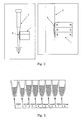
- Fig. 2 shows the state in which the magnetic material (1) and the tip (2) were set in the apparatus.
- the tip for performing sucking/discharging, set in the apparatus were disposable tip (2) made of polypropylene and had an inner diameter of about 2.25 mm and a wall thickness of about 0.75 mm at the site where the magnetic particles (3) are collected (magnetic force site).
- An automatic measuring cartridge having eight vessels connected thereto was used as the automatic measuring cartridge.
- the solutions containing magnetic particles used were three types of commercially available solutions containing magnetic particles, i.e., a solution containing magnetic particles having carried thereon HTLV-1 antigen (hereinafter, also referred to as "HTLV-1 magnetic particle reagent”: Lumipulse HTLV-1, manufactured by FUJIREBIO), a solution containing magnetic particles having carried thereon TP-N antigen (hereinafter, also referred to as "TP-N magnetic particle reagent”: Lumipulse II TP-N, manufactured by FUJIREBIO), and a solution containing magnetic particles having carried thereon no antigen (RP-M1: manufactured by Rohne Poulenc).
- a commercially available B/F washing solution (Lumipulse washing solution, LOT NO. JJ2080, manufactured by FUJIREBIO) was used as the washing solution for B/F separation.
- the recovery of magnetic particles was evaluagted by absorbance.
- the measurement of the absorbance of the solutions was performed using a spectrophotometer Multiskan MS (manufactured by Labsystem Corporation).
- the measurement of absorbance was performed at a measuring wavelength of 490 nm.
- Magnetic particle recovery rate (%) ((B-b)/(A-a)) x (200/150) x 100
- A is an absorbance of the solution containing the magnetic particles obtained in advance before the measurement
- a is an absorbance of the dispersant obtained in advance before the measurement
- B is an absorbance of the solution containing the magnetic particles obtained as a result of the measurement
- b is an absorbance of the B/F washing solution that serves as the dispersant for the magnetic particles in the vessel 8.
- a the absorbance obtained by separately isolating two types of the solutions containing the magnetic particles described in (2) above, centrifuging the solutions to recover only the dispersant as a supernatant, and measuring the supernatant was used.
- the "(200/150)" is a correction of volume.
- the amount of the solution in which the magnetic particles were first contained is 150 ⁇ l (vessel 2), from which the magnetic particles were recovered by the magnetic force, and finally dispersed in 200 ⁇ l of the solution (vessel 8), and the absorbance was measured. From this, the obtained absorbance was multiplied with a liquid amount ratio of 200/150 to correct the amount of the liquid, thus obtaining the recovery rate.
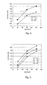
- results of the measurements using the HTLV-1 magnetic particle reagent are shown in Table 1 and the results in the form of a graph are illustrated in Fig. 4.
- results of the measurements using the TP-N magnetic particle reagent are shown in Table 2 and the results in the form of a graph are illustrated in Fig. 5.
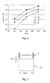
- results of the measurement using the magnetic particles having carried thereon no antigen are shown in Table 3 and the results in the form of a graph are illustrated in Fig. 6.
- the results of the experiments using the HTLV-1 magnetic particle reagent and the TP-N magnetic particle reagent indicate that by using either types of the magnetic particles, the layered magnetic materials B and C could collect the magnetic particles much more efficiently than the magnetic material A consisting of a single magnet. When the collection time was prolonged, higher recovery rates were obtained and a high recovery rate of 90% or more was achieved at 240 sec.
- Example 2 Using the magnet materials prepared in Example 1 above, an immunoassay using magnetic particles was performed and the results obtained were analyzed.
- the apparatus, the magnetic material, the tip and the cartridge were the same as those used in Example 2 above were employed.
- the magnetic materials A and C prepared in Example 1 were used as the magnetic material.
- HBs-Ag magnetic particle reagent Lumipulse II HBs-Ag, Lot No. NC3022, manufactured by FUJIREBIO
- samples containing an HIV antibody were measured using the magnetic particles having carried thereon an HIV antigen (hereinafter, also referred to as "HIV magnetic particle reagent", Lumipulse ortho HIV-1/2, Lot No. CD2104, manufactured by FUJIREBIO).
- Example 1 the effects of the magnetic material of the present invention having a plurality of magnets layered were confirmed. Accordingly, further detailed analysis of the magnetic force was performed on the magnetic materials A, B, C, and D prepared in Example 1 above.
- the magnetic force of each magnetic material was measured using a handy gauss meter (MODEL 4048: manufactured by F. W. BELL) and a measuring probe (T-4048-001 Type: manufactured by F. W. BELL).
- a measuring portion of a probe (4) was set vertically on a pole surface of a magnetic material (5), which is a target to be measured, at a distance of 1 mm from the magnetic pole surface.
- the magnetic materials A, B, and C were measured for the magnetic force at respective points while moving the measuring probe by 2.5 mm from one end to the other end of the magnetic pole surface.
- the magnetic material D was measured for the magnetic force at respective points while moving the magnetic material by 1.5 mm from one end to the other end of the magnetic pole surface.
- graphical representation of the measurements for the magnetic force continuously measured at pole surfaces of the respective magnetic materials indicates as shown in Fig. 8 that the magnetic materials had their own peaks of magnetic force and number of peaks.
- the magnetic material A which is a single magnet-magnetic material
- a strong magnetic force was observed only at the end of the magnetic material.
- the magnetic material B having layered two magnets had a peak of magnetic force in one layered portion of the magnets that is present in the pole surface of the magnetic material besides the peaks at the both ends of the magnetic material and a strong magnetic force of 1,000 gausses or more was measured.
- the magnetic material C having layered three magnets had peaks of magnetic force in two layered portions that are present in the pole surface of the magnetic material besides the peaks at the both ends of the magnetic material and a strong magnetic force of 1,000 gausses or more was measured.
- the magnetic material D having layered five magnets had peaks of magnetic force at four layered portions that are present in the center of the magnetic material besides the two peaks at the both ends of the magnetic material and the every peak has a low magnetic force of 600 gausses or less, thus showing no clear peak shapes.
- the magnetic materials of the present invention have properties of exhibiting strong magnetic force not only on the end(s) of the magnetic material but also at layered portions of the magnets. From the lack of strong magnetic force peaks of above 600 gausses in the magnetic material D and the small, unclear shapes of the peaks, it was conceived that when a magnetic material having an outer size on the order of 15 mm in longitudinal length x 14 mm in transversal length x 4 mm in width, use of five or more magnets leads to an insufficient magnetic force.
- the size of the magnetic material of the present invention can be determined to have an optimum configuration taking into consideration the results of such measurements as indicator. These results coincide with the results obtained in Examples 2 and 3.
- the magnetic materials B and C of the present invention have at least one magnetic force peak in the magnetic pole surface besides peaks at the ends of the magnetic material, and the magnetic force thereof is as high as 1,000 gausses or more. This indicates that the magnetic materials B and C had an ability to collect the magnetic particles more efficiently than the magnetic material A, which is a single magnet-magnetic material.
- the magnetic material D has a peak of magnetic force in the magnetic pole surface, but the peak magnetic force is 600 gausses or less and is insufficient.
- the recovery rate of the magnetic particles decreased as compared with that of the magnetic material A.
- Examples 1 to 4 confirms two major features of the magnetic materials of the present invention, (1) strong magnetic forces can be generated not only on the ends of the magnetic material but also in the layered portions of the magnets, and (2) the magnetic lines accumulate near the magnetic pole surface and the magnetic force can be effectively exerted onto a tip or the like used as a liquid suction line. Accordingly, the magnetic materials are particularly useful for collecting the magnetic particles.
- the magnetic material of the present invention and the method of collecting the magnetic particles according to the present invention, collection of the magnetic particles can be performed with a very high accuracy, stably and at a high speed. This makes it possible to perform measurements with a high accuracy even in an immunoassays etc. that require B/F separation in a plurality of times. Also, the present invention allows down-sizing of the magnetic material, so that the apparatus can reduce its size.
Landscapes
- Health & Medical Sciences (AREA)
- Immunology (AREA)
- Life Sciences & Earth Sciences (AREA)
- Chemical & Material Sciences (AREA)
- Engineering & Computer Science (AREA)
- Physics & Mathematics (AREA)
- Pathology (AREA)
- General Physics & Mathematics (AREA)
- General Health & Medical Sciences (AREA)
- Biochemistry (AREA)
- Analytical Chemistry (AREA)
- Biomedical Technology (AREA)
- Molecular Biology (AREA)
- Urology & Nephrology (AREA)
- Hematology (AREA)
- Cell Biology (AREA)
- Microbiology (AREA)
- Medicinal Chemistry (AREA)
- Food Science & Technology (AREA)
- Biotechnology (AREA)
- Inorganic Chemistry (AREA)
- Automatic Analysis And Handling Materials Therefor (AREA)
- Investigating Or Analysing Materials By The Use Of Chemical Reactions (AREA)
- Sampling And Sample Adjustment (AREA)
- Investigating Or Analyzing Materials By The Use Of Magnetic Means (AREA)
Applications Claiming Priority (3)
| Application Number | Priority Date | Filing Date | Title |
|---|---|---|---|
| JP2002324177 | 2002-11-07 | ||
| JP2002324177 | 2002-11-07 | ||
| PCT/JP2003/014203 WO2004042400A1 (ja) | 2002-11-07 | 2003-11-07 | 磁性粒子捕集用磁力体及びその利用 |
Publications (3)
| Publication Number | Publication Date |
|---|---|
| EP1580555A1 true EP1580555A1 (de) | 2005-09-28 |
| EP1580555A4 EP1580555A4 (de) | 2008-11-26 |
| EP1580555B1 EP1580555B1 (de) | 2014-02-12 |
Family
ID=32310437
Family Applications (1)
| Application Number | Title | Priority Date | Filing Date |
|---|---|---|---|
| EP03810654.8A Expired - Lifetime EP1580555B1 (de) | 2002-11-07 | 2003-11-07 | Magnetisches material zum aufsammeln magnetischer partikel und dessen verwendung |
Country Status (7)
| Country | Link |
|---|---|
| US (3) | US20050202573A1 (de) |
| EP (1) | EP1580555B1 (de) |
| JP (2) | JP4732755B2 (de) |
| CN (2) | CN100538362C (de) |
| AU (1) | AU2003277611A1 (de) |
| ES (1) | ES2461242T3 (de) |
| WO (1) | WO2004042400A1 (de) |
Cited By (4)
| Publication number | Priority date | Publication date | Assignee | Title |
|---|---|---|---|---|
| WO2008145712A1 (en) * | 2007-05-29 | 2008-12-04 | Invitrogen Dynal A/S | A magnetising portion for a magnetic separation device |
| WO2012047653A3 (en) * | 2010-09-27 | 2012-07-05 | The General Hospital Corporation | Self-assembled magnetic arrays |
| EP2109504A4 (de) * | 2007-02-08 | 2013-12-11 | Biokit Sa | Station zur reinigung magnetischer partikel |
| US9199247B2 (en) | 2007-05-29 | 2015-12-01 | Invitrogen Dynal As | Magnetic separation rack |
Families Citing this family (36)
| Publication number | Priority date | Publication date | Assignee | Title |
|---|---|---|---|---|
| TW200704518A (en) * | 2005-07-20 | 2007-02-01 | Hitachi Metals Ltd | Screen printing apparatus and screen priting method |
| EP2044402B2 (de) * | 2006-07-24 | 2016-11-30 | Becton Dickinson and Company | Vorrichtung und Verfahren zur Durchführung eines Assays mittels magnetischer Partikeln. |
| US20080083291A1 (en) * | 2006-10-06 | 2008-04-10 | Promega Corporation | Apparatus and method for separating magnetic particles from a solution |
| FR2957823B1 (fr) * | 2010-03-29 | 2015-02-27 | Snecma | Dispositif et procede de recuperation de particules magnetiques piegees sur un bouchon magnetique |
| EP2537589A1 (de) * | 2011-06-21 | 2012-12-26 | Siemens Aktiengesellschaft | Verfahren zum Trennen eines ersten Stoffes aus einem fließfähigen Primärstoffstrom, Vorrichtung zum Trennen eines ersten Stoffes aus einem fließfähigen Primärstoffstrom und Steuer- und/oder Regeleinrichtung |
| EP2634579B1 (de) * | 2012-03-03 | 2014-12-17 | Astrium GmbH | Verfahren zur Durchführung von Immuno-Assays in Schwerelosigkeit |
| AT513642B1 (de) * | 2012-11-28 | 2014-10-15 | Barilits Gupta Maria Michaela | Vorrichtung zur magnetischen Behandlung eines kohlenwasserstoffhaltigen Fluids |
| CN105259342A (zh) * | 2013-06-08 | 2016-01-20 | 张沈平 | 一种用于胶体金读卡仪的测试方法及胶体金读卡仪 |
| US9078427B1 (en) | 2014-08-29 | 2015-07-14 | Pioneer Hi Bred International Inc | Method of storing plant embryos |
| US11111548B2 (en) * | 2014-08-29 | 2021-09-07 | Pioneer Hi-Bred International, Inc. | Systems and methods for genotyping seed components |
| CA2954981C (en) | 2014-08-29 | 2023-01-03 | Pioneer Hi-Bred International, Inc. | Methods and devices involving oil matrices |
| US10280472B2 (en) | 2014-08-29 | 2019-05-07 | Pioneer Hi-Bred International, Inc. | Systems and methods for genotyping seed components |
| CN107208136A (zh) * | 2014-12-18 | 2017-09-26 | 通用电气医疗集团英国有限公司 | 通过与免疫测定法偶联的核酸扩增的固体支持物上的分析物检测 |
| EP3061529A1 (de) | 2015-02-24 | 2016-08-31 | AdnaGen GmbH | Vorrichtung und Verfahren zur Analyse, Isolierung und/oder Anreicherung von Zielstrukturen in einer Flüssigkeitsprobe |
| CZ2015141A3 (cs) * | 2015-02-26 | 2016-09-14 | Univerzita PalackĂ©ho v Olomouci | Zařízení pro magnetickou separaci feromagnetických částic, sada pro magnetickou separaci částic, způsob separace magnetických částic z roztoku a použití zařízení nebo sady pro magnetickou separaci částic |
| CN104759140A (zh) * | 2015-03-26 | 2015-07-08 | 常州回天新材料有限公司 | 一种水处理膜组件上的过滤装置 |
| CN105413858A (zh) * | 2016-01-11 | 2016-03-23 | 潘静娴 | 一种利用微小磁极距形成高密度磁峰值的磁选装置 |
| CN105586258B (zh) * | 2016-03-14 | 2018-08-17 | 佛山市汇广健医疗科技有限公司 | 磁性吸附转移棒 |
| KR101918115B1 (ko) * | 2017-01-25 | 2019-01-29 | 메디엇 주식회사 | 화합물 분리장치 및 이를 이용한 화학발광 면역검정장치 |
| JP6979797B2 (ja) * | 2017-05-31 | 2021-12-15 | シスメックス株式会社 | 固液分離方法、固液分離装置およびそれに用いるピペットチップ、粒子およびキット |
| JP6420433B1 (ja) * | 2017-09-12 | 2018-11-07 | 株式会社 マトリックス細胞研究所 | 反応促進装置及び反応促進方法 |
| US11571696B2 (en) | 2018-03-03 | 2023-02-07 | Applied Cells Inc. | Biological entity separation device and method of use |
| US12337319B2 (en) | 2018-03-03 | 2025-06-24 | Applied Cells Inc. | Microfluidic chip for acoustic separation of biological objects |
| US12544769B2 (en) | 2018-03-03 | 2026-02-10 | Applied Cells Inc. | Method and apparatus for magnetically sorting biological objects |
| US12145151B2 (en) | 2018-03-03 | 2024-11-19 | Applied Cells Inc. | Methods and apparatus to separate biological entities |
| JP6370018B1 (ja) * | 2018-03-15 | 2018-08-08 | 株式会社 マトリックス細胞研究所 | 反応促進装置及び反応促進方法 |
| JP6370017B1 (ja) * | 2018-03-15 | 2018-08-08 | 株式会社 マトリックス細胞研究所 | 反応促進装置及び反応促進方法 |
| JP7139931B2 (ja) * | 2018-12-14 | 2022-09-21 | 株式会社島津製作所 | 磁性体粒子操作用容器及び磁性体粒子操作用装置 |
| KR102188470B1 (ko) * | 2019-04-25 | 2020-12-09 | 프리시젼바이오 주식회사 | 진단 장치의 구동 방법 |
| CN111208192B (zh) * | 2020-01-15 | 2021-09-14 | 中国科学院生态环境研究中心 | 环境中磁性Fe3O4纳米颗粒分离、提取的循环富集装置及其检测方法 |
| CN111540559B (zh) * | 2020-05-11 | 2022-03-29 | 北京机械设备研究所 | 一种用于高温超导磁悬浮装置的超导块混合排布结构 |
| CN111804427A (zh) * | 2020-07-24 | 2020-10-23 | 深圳沃德生命科技有限公司 | 用于磁性颗粒的收集结构 |
| JP7722998B2 (ja) * | 2020-09-09 | 2025-08-13 | 富士レビオ株式会社 | 検体処理装置及び方法 |
| US12090481B2 (en) | 2020-11-03 | 2024-09-17 | Applied Cells Inc. | Microfluidic system including cooling device |
| CN115156215A (zh) * | 2022-08-02 | 2022-10-11 | 宋世琦 | 用于免疫分析设备的磁微粒清洗装置及清洗方法 |
| JPWO2024095740A1 (de) * | 2022-10-31 | 2024-05-10 |
Family Cites Families (26)
| Publication number | Priority date | Publication date | Assignee | Title |
|---|---|---|---|---|
| US4988618A (en) * | 1987-11-16 | 1991-01-29 | Gene-Trak Systems | Magnetic separation device and methods for use in heterogeneous assays |
| EP0374251A4 (en) * | 1988-05-25 | 1990-09-05 | Ukrainsky Institut Inzhenerov Vodnogo Khozyaistva | Device for separating ferromagnetic materials from fluid media |
| JPH079674Y2 (ja) * | 1988-10-07 | 1995-03-08 | 蛇の目ミシン工業株式会社 | 毛筆プロッタにおける印字用紙固定機構 |
| IL100866A (en) | 1991-02-06 | 1995-10-31 | Igen Inc | Method and apparatus for magnetic microparticulate based luminescence assay including plurality of magnets |
| IL100867A (en) | 1991-02-06 | 1995-12-08 | Igen Inc | Method and apparatus for improved luminescence assays |
| US5424703A (en) * | 1992-05-08 | 1995-06-13 | The Electrodyne Company, Inc. | Magnetization of permanent magnet strip materials |
| FI932866A0 (fi) * | 1993-06-21 | 1993-06-21 | Labsystems Oy | Separeringsfoerfarande |
| EP1130397B1 (de) | 1993-02-01 | 2006-10-11 | Thermo Electron Oy | Gerät zur Bestimmung eines Analyten in einer Probe |
| EP0697916B1 (de) * | 1994-03-14 | 2002-06-05 | Nexell Therapeutics Inc. | Verfahren und apparat zum semi-automatisierten trennen von zellen |
| JP3115501B2 (ja) * | 1994-06-15 | 2000-12-11 | プレシジョン・システム・サイエンス株式会社 | 分注機を利用した磁性体の脱着制御方法及びこの方法によって処理される各種装置 |
| US5837144A (en) * | 1994-06-16 | 1998-11-17 | Boehringer Mannheim Gmbh | Method of magnetically separating liquid components |
| DE4421058A1 (de) | 1994-06-16 | 1995-12-21 | Boehringer Mannheim Gmbh | Verfahren zur magnetischen Abtrennung von Flüssigkeitskomponenten |
| JP3013937U (ja) | 1995-01-24 | 1995-07-25 | オカモト株式会社 | 折り畳み椅子 |
| JPH08304399A (ja) * | 1995-04-28 | 1996-11-22 | Mitsubishi Chem Corp | 磁性体粒子の分離方法およびそれを用いた免疫分析方法 |
| AU1811197A (en) | 1996-02-25 | 1997-09-10 | Precision System Science Co., Ltd. | Method for treating biopolymers, microorganisms or materials by using more than one type of magnetic particles |
| JP3658857B2 (ja) * | 1996-05-08 | 2005-06-08 | 富士レビオ株式会社 | 凝集反応測定用磁石板とその使用方法 |
| EP0965842B1 (de) * | 1996-05-20 | 2010-03-17 | Precision System Science Co., Ltd. | Prozess und apparat zur kontrolle magnetischer teilchen mit hilfe einer pipettier-maschine |
| US6292680B1 (en) * | 1997-05-21 | 2001-09-18 | Christopher P. Somogyi | Non-invasive sensing of a physical parameter |
| US5898352A (en) * | 1997-11-24 | 1999-04-27 | T. D. Wright, Inc. | Magnetic cylinder with thin foraminate layer between cylinder core and magnetic elements |
| US6036857A (en) * | 1998-02-20 | 2000-03-14 | Florida State University Research Foundation, Inc. | Apparatus for continuous magnetic separation of components from a mixture |
| CN1128023C (zh) * | 1999-05-31 | 2003-11-19 | 中国科学院化工冶金研究所 | 从流体中分离磁性颗粒的连续式高梯度磁分离方法及装置 |
| US6514415B2 (en) * | 2000-01-31 | 2003-02-04 | Dexter Magnetic Technologies, Inc. | Method and apparatus for magnetic separation of particles |
| JP3309854B1 (ja) * | 2001-07-27 | 2002-07-29 | ソニー株式会社 | 磁気吸着シートおよびその製造方法 |
| US20030138819A1 (en) * | 2001-10-26 | 2003-07-24 | Haiqing Gong | Method for detecting disease |
| JP3115501U (ja) | 2005-06-15 | 2005-11-10 | タイフレックス株式会社 | 保護カバー付水栓用フレキシブル継手管 |
| JP3128541U (ja) | 2006-10-06 | 2007-01-18 | 金造 久保 | 浸透枡 |
-
2003
- 2003-11-07 CN CNB2003801083872A patent/CN100538362C/zh not_active Expired - Lifetime
- 2003-11-07 JP JP2004549639A patent/JP4732755B2/ja not_active Expired - Lifetime
- 2003-11-07 CN CN2008101661862A patent/CN101398428B/zh not_active Expired - Lifetime
- 2003-11-07 WO PCT/JP2003/014203 patent/WO2004042400A1/ja not_active Ceased
- 2003-11-07 EP EP03810654.8A patent/EP1580555B1/de not_active Expired - Lifetime
- 2003-11-07 AU AU2003277611A patent/AU2003277611A1/en not_active Abandoned
- 2003-11-07 ES ES03810654.8T patent/ES2461242T3/es not_active Expired - Lifetime
-
2005
- 2005-05-05 US US11/121,937 patent/US20050202573A1/en not_active Abandoned
-
2010
- 2010-05-24 JP JP2010118846A patent/JP2010230683A/ja active Pending
-
2014
- 2014-09-05 US US14/478,345 patent/US10677695B2/en not_active Expired - Lifetime
-
2020
- 2020-04-30 US US16/862,855 patent/US20200256773A1/en not_active Abandoned
Non-Patent Citations (2)
| Title |
|---|
| No further relevant documents disclosed * |
| See also references of WO2004042400A1 * |
Cited By (10)
| Publication number | Priority date | Publication date | Assignee | Title |
|---|---|---|---|---|
| EP2109504A4 (de) * | 2007-02-08 | 2013-12-11 | Biokit Sa | Station zur reinigung magnetischer partikel |
| EP3219389A1 (de) * | 2007-02-08 | 2017-09-20 | Biokit S.A. | Station zur reinigung magnetischer partikel |
| US11536718B2 (en) | 2007-02-08 | 2022-12-27 | Biokit, S.A. | Magnetic particle washing station |
| WO2008145712A1 (en) * | 2007-05-29 | 2008-12-04 | Invitrogen Dynal A/S | A magnetising portion for a magnetic separation device |
| US8574515B2 (en) | 2007-05-29 | 2013-11-05 | Life Technologies As | Magnetic separating device |
| US9199247B2 (en) | 2007-05-29 | 2015-12-01 | Invitrogen Dynal As | Magnetic separation rack |
| US9227199B2 (en) | 2007-05-29 | 2016-01-05 | Life Technologies As | Magnetising portion for a magnetic separation device |
| WO2012047653A3 (en) * | 2010-09-27 | 2012-07-05 | The General Hospital Corporation | Self-assembled magnetic arrays |
| US9532729B2 (en) | 2010-09-27 | 2017-01-03 | The General Hospital Corporation | Self-assembled magnetic arrays |
| US9869619B2 (en) | 2010-09-27 | 2018-01-16 | The General Hospital Corporation | Self-assembled magnetic arrays |
Also Published As
| Publication number | Publication date |
|---|---|
| JPWO2004042400A1 (ja) | 2006-03-09 |
| US20200256773A1 (en) | 2020-08-13 |
| EP1580555A4 (de) | 2008-11-26 |
| CN1735806A (zh) | 2006-02-15 |
| US20140377882A1 (en) | 2014-12-25 |
| EP1580555B1 (de) | 2014-02-12 |
| HK1088661A1 (zh) | 2006-11-10 |
| CN101398428A (zh) | 2009-04-01 |
| CN100538362C (zh) | 2009-09-09 |
| ES2461242T3 (es) | 2014-05-19 |
| US20050202573A1 (en) | 2005-09-15 |
| JP2010230683A (ja) | 2010-10-14 |
| JP4732755B2 (ja) | 2011-07-27 |
| CN101398428B (zh) | 2012-09-05 |
| AU2003277611A1 (en) | 2004-06-07 |
| HK1129730A1 (en) | 2009-12-04 |
| WO2004042400A1 (ja) | 2004-05-21 |
| US10677695B2 (en) | 2020-06-09 |
Similar Documents
| Publication | Publication Date | Title |
|---|---|---|
| US20200256773A1 (en) | Magnetic material for collecting magnetic particles and utilization thereof | |
| CN109870582B (zh) | 一种多靶标磁免疫化学发光微流控芯片检测平台及方法 | |
| EP2279790B1 (de) | Probenplatte | |
| EP2488871B1 (de) | Testverfahren unter verwendung magnetischer partikel | |
| RU2456618C2 (ru) | Система и способ обнаружения с помощью магнитной и/или электрической метки | |
| US20230109130A1 (en) | Methods and systems related to highly sensitive assays and delivering capture objects | |
| JPH0670630B2 (ja) | 分析法 | |
| EP3552020A1 (de) | Kombinierter immunoassay und magnetische immunoassay-systeme und vorrichtungen für erweiterten empfindlichkeitsbereich | |
| JP4167491B2 (ja) | 全血測定法 | |
| EP1194781B1 (de) | Verfahren zur prozessführung chemilumineszenter bindungstests | |
| WO2010086772A1 (en) | System and method for assay | |
| HK1088661B (en) | Magnetic particle collecting magnetic force body and its use | |
| HK1129730B (en) | Magnetic particle collecting magnetic force body and its use | |
| JP4567326B2 (ja) | 全血を用いる測定法 | |
| Kim | Redox cycling for an in-situ enzyme labeled immunoassay on interdigitated array electrodes | |
| HK1066861B (en) | Method of measuring whole blood |
Legal Events
| Date | Code | Title | Description |
|---|---|---|---|
| PUAI | Public reference made under article 153(3) epc to a published international application that has entered the european phase |
Free format text: ORIGINAL CODE: 0009012 |
|
| 17P | Request for examination filed |
Effective date: 20050520 |
|
| AK | Designated contracting states |
Kind code of ref document: A1 Designated state(s): AT BE BG CH CY CZ DE DK EE ES FI FR GB GR HU IE IT LI LU MC NL PT RO SE SI SK TR |
|
| AX | Request for extension of the european patent |
Extension state: AL LT LV MK |
|
| DAX | Request for extension of the european patent (deleted) | ||
| RBV | Designated contracting states (corrected) |
Designated state(s): DE ES FR GB IT |
|
| A4 | Supplementary search report drawn up and despatched |
Effective date: 20081029 |
|
| RAP1 | Party data changed (applicant data changed or rights of an application transferred) |
Owner name: MITSUBISHI CHEMICAL MEDIENCE CORPORATION |
|
| 17Q | First examination report despatched |
Effective date: 20110907 |
|
| GRAP | Despatch of communication of intention to grant a patent |
Free format text: ORIGINAL CODE: EPIDOSNIGR1 |
|
| INTG | Intention to grant announced |
Effective date: 20130717 |
|
| GRAS | Grant fee paid |
Free format text: ORIGINAL CODE: EPIDOSNIGR3 |
|
| RIN1 | Information on inventor provided before grant (corrected) |
Inventor name: SORIN, TAKAAKI Inventor name: KOYATA, ATSUSHI |
|
| GRAA | (expected) grant |
Free format text: ORIGINAL CODE: 0009210 |
|
| AK | Designated contracting states |
Kind code of ref document: B1 Designated state(s): DE ES FR GB IT |
|
| REG | Reference to a national code |
Ref country code: GB Ref legal event code: FG4D |
|
| REG | Reference to a national code |
Ref country code: DE Ref legal event code: R096 Ref document number: 60345713 Country of ref document: DE Effective date: 20140320 |
|
| REG | Reference to a national code |
Ref country code: ES Ref legal event code: FG2A Ref document number: 2461242 Country of ref document: ES Kind code of ref document: T3 Effective date: 20140519 |
|
| REG | Reference to a national code |
Ref country code: DE Ref legal event code: R097 Ref document number: 60345713 Country of ref document: DE |
|
| PLBE | No opposition filed within time limit |
Free format text: ORIGINAL CODE: 0009261 |
|
| STAA | Information on the status of an ep patent application or granted ep patent |
Free format text: STATUS: NO OPPOSITION FILED WITHIN TIME LIMIT |
|
| 26N | No opposition filed |
Effective date: 20141113 |
|
| REG | Reference to a national code |
Ref country code: DE Ref legal event code: R097 Ref document number: 60345713 Country of ref document: DE Effective date: 20141113 |
|
| REG | Reference to a national code |
Ref country code: DE Ref legal event code: R082 Ref document number: 60345713 Country of ref document: DE Representative=s name: HOFFMANN - EITLE PATENT- UND RECHTSANWAELTE PA, DE |
|
| REG | Reference to a national code |
Ref country code: ES Ref legal event code: PC2A Owner name: LSI MEDIENCE CORPORATION Effective date: 20150406 |
|
| REG | Reference to a national code |
Ref country code: DE Ref legal event code: R081 Ref document number: 60345713 Country of ref document: DE Owner name: LSI MEDIENCE CORPORATION, JP Free format text: FORMER OWNER: MITSUBISHI CHEMICAL MEDIENCE CORP., TOKYO, JP Effective date: 20150316 Ref country code: DE Ref legal event code: R081 Ref document number: 60345713 Country of ref document: DE Owner name: LSI MEDIENCE CORPORATION, JP Free format text: FORMER OWNER: MITSUBISHI KAGAKU IATRON, INC., TOKIO/TOKYO, JP Effective date: 20140212 Ref country code: DE Ref legal event code: R082 Ref document number: 60345713 Country of ref document: DE Representative=s name: HOFFMANN - EITLE PATENT- UND RECHTSANWAELTE PA, DE Effective date: 20150316 |
|
| REG | Reference to a national code |
Ref country code: FR Ref legal event code: CD Owner name: LSI MEDIENCE CORPORATION, JP Effective date: 20150609 Ref country code: FR Ref legal event code: CA Effective date: 20150609 |
|
| REG | Reference to a national code |
Ref country code: FR Ref legal event code: PLFP Year of fee payment: 13 |
|
| REG | Reference to a national code |
Ref country code: FR Ref legal event code: PLFP Year of fee payment: 14 |
|
| REG | Reference to a national code |
Ref country code: FR Ref legal event code: PLFP Year of fee payment: 15 |
|
| PGFP | Annual fee paid to national office [announced via postgrant information from national office to epo] |
Ref country code: IT Payment date: 20221123 Year of fee payment: 20 Ref country code: GB Payment date: 20221128 Year of fee payment: 20 Ref country code: FR Payment date: 20221123 Year of fee payment: 20 Ref country code: ES Payment date: 20221201 Year of fee payment: 20 Ref country code: DE Payment date: 20221125 Year of fee payment: 20 |
|
| REG | Reference to a national code |
Ref country code: DE Ref legal event code: R071 Ref document number: 60345713 Country of ref document: DE |
|
| REG | Reference to a national code |
Ref country code: ES Ref legal event code: FD2A Effective date: 20231128 |
|
| REG | Reference to a national code |
Ref country code: GB Ref legal event code: PE20 Expiry date: 20231106 |
|
| PG25 | Lapsed in a contracting state [announced via postgrant information from national office to epo] |
Ref country code: GB Free format text: LAPSE BECAUSE OF EXPIRATION OF PROTECTION Effective date: 20231106 |
|
| PG25 | Lapsed in a contracting state [announced via postgrant information from national office to epo] |
Ref country code: ES Free format text: LAPSE BECAUSE OF EXPIRATION OF PROTECTION Effective date: 20231108 |
|
| PG25 | Lapsed in a contracting state [announced via postgrant information from national office to epo] |
Ref country code: GB Free format text: LAPSE BECAUSE OF EXPIRATION OF PROTECTION Effective date: 20231106 Ref country code: ES Free format text: LAPSE BECAUSE OF EXPIRATION OF PROTECTION Effective date: 20231108 |