EP1580512B1 - Appareil de chauffage comprenant un dispositif d'actionnement à mémoire de forme - Google Patents
Appareil de chauffage comprenant un dispositif d'actionnement à mémoire de forme Download PDFInfo
- Publication number
- EP1580512B1 EP1580512B1 EP04425206A EP04425206A EP1580512B1 EP 1580512 B1 EP1580512 B1 EP 1580512B1 EP 04425206 A EP04425206 A EP 04425206A EP 04425206 A EP04425206 A EP 04425206A EP 1580512 B1 EP1580512 B1 EP 1580512B1
- Authority
- EP
- European Patent Office
- Prior art keywords
- shape memory
- trigger element
- heating device
- memory wire
- deformable
- Prior art date
- Legal status (The legal status is an assumption and is not a legal conclusion. Google has not performed a legal analysis and makes no representation as to the accuracy of the status listed.)
- Expired - Lifetime
Links
Images

Classifications
-
- F—MECHANICAL ENGINEERING; LIGHTING; HEATING; WEAPONS; BLASTING
- F28—HEAT EXCHANGE IN GENERAL
- F28D—HEAT-EXCHANGE APPARATUS, NOT PROVIDED FOR IN ANOTHER SUBCLASS, IN WHICH THE HEAT-EXCHANGE MEDIA DO NOT COME INTO DIRECT CONTACT
- F28D20/00—Heat storage plants or apparatus in general; Regenerative heat-exchange apparatus not covered by groups F28D17/00 or F28D19/00
- F28D20/02—Heat storage plants or apparatus in general; Regenerative heat-exchange apparatus not covered by groups F28D17/00 or F28D19/00 using latent heat
- F28D20/028—Control arrangements therefor
-
- C—CHEMISTRY; METALLURGY
- C08—ORGANIC MACROMOLECULAR COMPOUNDS; THEIR PREPARATION OR CHEMICAL WORKING-UP; COMPOSITIONS BASED THEREON
- C08L—COMPOSITIONS OF MACROMOLECULAR COMPOUNDS
- C08L2201/00—Properties
- C08L2201/12—Shape memory
-
- F—MECHANICAL ENGINEERING; LIGHTING; HEATING; WEAPONS; BLASTING
- F28—HEAT EXCHANGE IN GENERAL
- F28F—DETAILS OF HEAT-EXCHANGE AND HEAT-TRANSFER APPARATUS, OF GENERAL APPLICATION
- F28F2255/00—Heat exchanger elements made of materials having special features or resulting from particular manufacturing processes
- F28F2255/04—Heat exchanger elements made of materials having special features or resulting from particular manufacturing processes comprising shape memory alloys or bimetallic elements
-
- Y—GENERAL TAGGING OF NEW TECHNOLOGICAL DEVELOPMENTS; GENERAL TAGGING OF CROSS-SECTIONAL TECHNOLOGIES SPANNING OVER SEVERAL SECTIONS OF THE IPC; TECHNICAL SUBJECTS COVERED BY FORMER USPC CROSS-REFERENCE ART COLLECTIONS [XRACs] AND DIGESTS
- Y02—TECHNOLOGIES OR APPLICATIONS FOR MITIGATION OR ADAPTATION AGAINST CLIMATE CHANGE
- Y02E—REDUCTION OF GREENHOUSE GAS [GHG] EMISSIONS, RELATED TO ENERGY GENERATION, TRANSMISSION OR DISTRIBUTION
- Y02E60/00—Enabling technologies; Technologies with a potential or indirect contribution to GHG emissions mitigation
- Y02E60/14—Thermal energy storage
Definitions
- the present invention relates to heating devices of the type comprising a container containing one or more chemical compounds for releasing heat following upon a change of phase thereof (crystallization, solidification, ...) and a deformable element to trigger the same change of phase, placed inside the container.
- a heating device as set forth in the preamble of claim 1 is known from JP 01 274838, JP 02 005909 AND JP 02 171594.
- a heating device where the release of heat from supercooled material is triggered by a shape memory actuator is also known from US 4 850 424.
- the aim of the present patent is that of improving the devices of the type above illustrated in order to allow their application in various fields where a remote control of the trigger element of the change of the phase could be useful.
- a further aim of the invention is that of providing such a device with extremely simple and efficient means, that will not require a high consumption of energy .
- the invention has as its object a heating device having the characteristics of claim 1.
- the shape memory actuators are themselves known and applied in various technical fields. They exploit the proprieties of particular metallic alloys to change the state above and below a determined transition temperature. A typical example is that of a shape memory wire which takes a shorter configuration when the temperature goes above a predetermined transition value.
- shape memory actuators are known having a completely different configuration, for example in the form of coil springs, of torsion bars or other. The applicant holds several patents relative to specific conformations of shape memory actuators and also to specific applications of said actuators.
- the heating of the shape memory actuator can be obtained either by exploiting directly the ambient temperatures in which the shape memory element is placed, or, in other cases, provoking the heating of the shape memory element by the Joule effect by passing through it an electric current.
- the present invention consists essentially of a new and advantageous application of a shape memory actuator for the control of the trigger element of the change of the phase in a heating device of the type mentioned above.
- the conformation and the disposition of the shape memory element can be selected having regard to the needs of each specific application, having particular regard to the necessity to reduce to the minimum the actuation time, and also the time that the shape memory element takes to return to the original condition after the actuation, and/or to obtain a high ratio power/weight of the shape memory element.
- a further advantage of the shape memory elements is that of presenting a high resistance to corrosion, and therefore it can be immersed in the chemical compound without problems.
- heating the fuel of a diesel engine is particularly interesting. Particularly during a cold start, it is generally necessary to heat the diesel fed to a diesel engine, in order to dissolve the paraffin waxes contained in the fuel on the walls of the ducts which supply the fuel to the engine.
- the heating device according to the invention is applicable in many other fields. For example, it could be exploited to heat the conditioned air fed into the inside of a vehicle. In an other example, it could be used to heat the cooling liquid of the engine in conditions of low temperature.
- FIG 1 With reference number 1 a heating device is shown in the whole realized in conformity to the principles of the invention.
- the device 1 is comprised of a container 2 containing one or more chemical compounds 3 for example a solution of sodium acetate, capable of releasing heat in consequence of its crystallization.
- the priming of the crystallization is obtained provoking the deformation of a metallic disc 4 immersed in the solution 3, with the peripheral edge secured to the wall of the container 2 and that, in the illustrated example, is placed with its plane perpendicularly to the longitudinal axis of the container 2.
- the disc 4 to prime the change of the phase of the chemical compound 3 could be deformed until it reaches the configuration shown with the dotted line through a shape memory wire 5 which is activated through an electronic control unit 6 which supplies an electric current through the wire 5.
- an electronic control unit 6 which supplies an electric current through the wire 5.
- the opposite ends of the wire 5 are connected, in some way, to the power unit 6.
- the wire 5 When the shape memory wire 5 is activated by the unit 6, the wire 5 is heating up and, when this goes above the transition temperature, it shortens determining the deformation of the metallic disc 4, because the end of the wire 5 opposite to the disc 4 is secured in 8 to a fixed structure.
- the ends of the shape memory wire could both be tied in 8 to a fixed structure. In this case the shape memory wire passes through holes in the metallic disc 4, and the wire is sent back in a U through such holes, in such a way to have a coming and going system, the shortening of which determines in the same way the deformation of the metallic disc 4.
- the deformation of the plate 4 triggers the priming of the change of the phase of the chemical compound 3 so that it releases heat immediately.
- An essential advantage of the invention rests with the very short time it takes to release the heat.
- Such advantage is added to the possibility to obtain an activation time of the shape memory wire 5 also extremely short, in the order of 100 ms.
- the waiting time for the wire 5 to go back to its initial condition after the activation is relatively short, in the order of a second.
- the use of the shape memory wire gives the possibility to obtain a high ratio power/weight with the consequent capacity to exercise the necessary force to activate the trigger for the change of the phase using a device of small dimensions.
- the shape memory wire is characterized also by the high resistance to corrosion, so that it can remain immersed in the chemical compound 3 without negative consequences.
- Figure 2 refers to a variation of figure 1, in which are foreseen two shape memory wires 5, 9 connected to the opposite sides of the metallic disc 4 in order to deform the disc 4 respectively towards the top (with reference to figure 2), or towards the bottom.
- the power unit 6 could be predisposed to supply alternatively electric current to the wires 5, 9, so that the disc 4 is deformed alternatively in the two opposite directions.
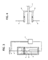
- Figure 3 shows yet again another variation, in which the disc 4 is connected from one side to the shape memory wire 5 which becomes activated through a supply of electric current, and from the other side to a shape memory wire 10 the activation of which is not obtained by passing electric current through it, but rather by the heat generated by an electric resistance 11 which is connected to the end of the wire 10 opposite to the disc 4.
- Figure 4 shows a variation substantially similar to that one of figure 2 where however the two shape memory wires 5, 9 are not connected directly to disc 4, but rather to the two rocker levers 12, 13 which cause the deformation of the disc.
Landscapes
- Engineering & Computer Science (AREA)
- Physics & Mathematics (AREA)
- Thermal Sciences (AREA)
- Mechanical Engineering (AREA)
- General Engineering & Computer Science (AREA)
- Temperature-Responsive Valves (AREA)
- Containers And Packaging Bodies Having A Special Means To Remove Contents (AREA)
- Resistance Heating (AREA)
- General Induction Heating (AREA)
- Yarns And Mechanical Finishing Of Yarns Or Ropes (AREA)
Claims (8)
- Dispositif de chauffage (1), comprenant :- un récipient (2) contenant un ou plusieurs composés chimiques (3) destinés à libérer de la chaleur à la suite d'une modification de phase de ceux-ci,caractérisé en ce que ledit élément de déclenchement déformable (4) a son bord périphérique fixé à la paroi du récipient (2) et en ce que ledit actionneur à mémoire de forme est constitué d'un fil droit à mémoire de forme (5) possédant une première extrémité (8) reliée à une structure fixe située à l'extérieur du récipient (2) et une autre partie reliée à l'élément de déclenchement déformable (4) situé à l'intérieur du récipient,
un élément de déclenchement déformable (4) destiné à déclencher cette modification de phase, placé à l'intérieur du récipient, et
un actionneur à mémoire de forme (5) destiné à mettre en oeuvre l'élément de déclenchement déformable (4),
ledit dispositif comprenant en outre une unité de commande électronique (6) destinée à fournir un courant électrique au fil à mémoire de forme (5) dans le but de le chauffer au-dessus de sa température de transition de façon à provoquer son raccourcissement, ce qui provoque ainsi une déformation de l'élément de déclenchement déformable (4), en déclenchant la libération de chaleur par lesdits composés. - Dispositif de chauffage selon la revendication 1, caractérisé en en ce que ladite autre partie du fil à mémoire de forme (5) a son extrémité opposée à ladite première extrémité.
- Dispositif de chauffage selon la revendication 1, caractérisé en ce que les deux extrémités du fil à mémoire de forme (5) sont reliées à la structure fixe, et en ce que l'élément de déclenchement déformable (4) se trouve sous la forme d'un disque métallique comportant des trous au travers desquels le fil à mémoire de forme (5) vient suivant une disposition en forme de U.
- Dispositif de chauffage selon la revendication 1, caractérisé en ce que ledit dispositif inclut un second fil à mémoire de forme (9) relié au dit élément de déclenchement déformable (4) depuis un côté opposé à celui qui relie le premier fil à mémoire de forme (5), ladite unité de commande électronique (6) convenant pour fournir un courant électrique alternativement aux premier et second fils à mémoire de forme (5, 9).
- Dispositif de chauffage selon la revendication 1, caractérisé en ce que ledit dispositif inclut un second fil à mémoire de forme (10) relié à l'élément de déclenchement déformable (4) depuis un côté opposé à celui sur lequel est relié le premier fil à mémoire de forme (5), un tel dispositif inclut également une résistance électrique (11) qui peut être alimentée avec du courant électrique dans le but de chauffer ledit second fil à mémoire de forme (10).
- Dispositif de chauffage selon la revendication 1, caractérisé en ce que ledit fil à mémoire de forme (5) est relié à l'élément de déclenchement déformable (4) par l'intermédiaire d'un élément intermédiaire (12) apte à provoquer la déformation dudit élément de déclenchement déformable (4).
- Dispositif de chauffage selon la revendication 6, caractérisé en ce que ledit dispositif inclut deux fils à mémoire de forme (5, 9) placés sur des côtés opposés par rapport à l'élément de déclenchement déformable et reliés à des leviers basculants respectifs (12, 13) capables de provoquer des déformations dudit élément de déclenchement (4) dans des sens opposés.
- Utilisation d'un dispositif de chauffage selon l'une quelconque des revendications précédentes pour chauffer du carburant approvisionnant un moteur diesel.
Priority Applications (4)
| Application Number | Priority Date | Filing Date | Title |
|---|---|---|---|
| ES04425206T ES2281770T3 (es) | 2004-03-24 | 2004-03-24 | Dispositivo de calentamiento provisto de un accionador con memoria de forma. |
| EP04425206A EP1580512B1 (fr) | 2004-03-24 | 2004-03-24 | Appareil de chauffage comprenant un dispositif d'actionnement à mémoire de forme |
| DE602004005155T DE602004005155T2 (de) | 2004-03-24 | 2004-03-24 | Heizvorrichtung mit Betätigungsvorrichtung aus Formgedächtnismaterial |
| AT04425206T ATE356329T1 (de) | 2004-03-24 | 2004-03-24 | Heizvorrichtung mit betätigungsvorrichtung aus formgedächtnismaterial |
Applications Claiming Priority (1)
| Application Number | Priority Date | Filing Date | Title |
|---|---|---|---|
| EP04425206A EP1580512B1 (fr) | 2004-03-24 | 2004-03-24 | Appareil de chauffage comprenant un dispositif d'actionnement à mémoire de forme |
Publications (2)
| Publication Number | Publication Date |
|---|---|
| EP1580512A1 EP1580512A1 (fr) | 2005-09-28 |
| EP1580512B1 true EP1580512B1 (fr) | 2007-03-07 |
Family
ID=34854754
Family Applications (1)
| Application Number | Title | Priority Date | Filing Date |
|---|---|---|---|
| EP04425206A Expired - Lifetime EP1580512B1 (fr) | 2004-03-24 | 2004-03-24 | Appareil de chauffage comprenant un dispositif d'actionnement à mémoire de forme |
Country Status (4)
| Country | Link |
|---|---|
| EP (1) | EP1580512B1 (fr) |
| AT (1) | ATE356329T1 (fr) |
| DE (1) | DE602004005155T2 (fr) |
| ES (1) | ES2281770T3 (fr) |
Families Citing this family (3)
| Publication number | Priority date | Publication date | Assignee | Title |
|---|---|---|---|---|
| EP2154021B1 (fr) | 2008-08-07 | 2010-09-15 | C.R.F. Società Consortile per Azioni | Dispositif de support ergonomique pour le corps d'un occupant, pour chaises ou sièges, notamment pour siège de véhicule automobile |
| DE102011005601A1 (de) * | 2010-03-16 | 2011-09-22 | Robert Bosch Gmbh | Aktuator und Verfahren zur Ansteuerung eines Aktuators zur Adaption einer Steifigkeit eines Deformationselements |
| DE102010046243A1 (de) * | 2010-09-22 | 2012-03-22 | Rawema Countertrade Handelsgesellschaft Mbh | Auslöseeinheit |
Family Cites Families (11)
| Publication number | Priority date | Publication date | Assignee | Title |
|---|---|---|---|---|
| JPS59208393A (ja) * | 1983-05-12 | 1984-11-26 | Sanden Corp | 蓄熱カプセル |
| JPS6048492A (ja) * | 1983-08-24 | 1985-03-16 | Hitachi Ltd | 蓄熱カプセル |
| JPS63135789A (ja) * | 1986-11-28 | 1988-06-08 | Nok Corp | 過冷却液体の任意固化装置 |
| JPH0760075B2 (ja) * | 1987-01-31 | 1995-06-28 | 株式会社東芝 | 蓄熱装置 |
| JPH01274838A (ja) * | 1988-04-25 | 1989-11-02 | Nok Corp | 過冷却液体の任意固化装置 |
| IT1217904B (it) * | 1988-06-23 | 1990-03-30 | Plurima Srl | Attivatore metallico per l'innesco della cristallizzazione di soluzioni saline in dispositivi di riscaldamento |
| JPH025909A (ja) * | 1988-06-25 | 1990-01-10 | Nok Corp | 保温容器およびその保温容器による保温方法 |
| JPH02171594A (ja) * | 1988-12-23 | 1990-07-03 | Mitsubishi Electric Corp | 蓄熱装置 |
| GB2260193A (en) * | 1991-10-04 | 1993-04-07 | Memory Metals Limited | Shaped memory devices |
| JPH08310562A (ja) * | 1995-03-14 | 1996-11-26 | Daisen Sangyo Kk | 冷却袋 |
| JP2002013893A (ja) * | 2000-06-27 | 2002-01-18 | Michiko Yamaguchi | 起熱装置を具備した潜熱放熱体 |
-
2004
- 2004-03-24 DE DE602004005155T patent/DE602004005155T2/de not_active Expired - Lifetime
- 2004-03-24 AT AT04425206T patent/ATE356329T1/de not_active IP Right Cessation
- 2004-03-24 ES ES04425206T patent/ES2281770T3/es not_active Expired - Lifetime
- 2004-03-24 EP EP04425206A patent/EP1580512B1/fr not_active Expired - Lifetime
Also Published As
| Publication number | Publication date |
|---|---|
| ATE356329T1 (de) | 2007-03-15 |
| DE602004005155T2 (de) | 2007-11-15 |
| EP1580512A1 (fr) | 2005-09-28 |
| DE602004005155D1 (de) | 2007-04-19 |
| ES2281770T3 (es) | 2007-10-01 |
Similar Documents
| Publication | Publication Date | Title |
|---|---|---|
| JP5575145B2 (ja) | 弁をシフトさせるための構造体 | |
| US3110633A (en) | Temperature-sustaining apparatus for automobiles | |
| AU2003222637B2 (en) | Phase change heat sink for use in electrical solenoids and motors | |
| US4977953A (en) | Latent heat regenerating apparatus | |
| CA2356728A1 (fr) | Appareil de chauffage de stockage thermique, et methode de regulation de l'apport et de la sortie de la chaleur dudit appareil | |
| CA1280045C (fr) | Methode et dispositif pour la formation de noyaux cristallins de materiaux sous-refroidis | |
| US20120168111A1 (en) | Heat transfer system utilizing thermal energy storage materials | |
| US20140007915A1 (en) | Thermoelectric generator for a vehicle and heat storage device for a thermoelectric generator of a vehicle | |
| JP5234721B2 (ja) | 冷熱蓄熱用マイクロカプセルを用いた氷蓄熱空調システム | |
| Mawire et al. | Performance comparison of four spherically encapsulated phase change materials for medium temperature domestic applications | |
| CN102569933A (zh) | 用于汽车的具有至少一个电化学的电芯和至少一个潜热储存器的电池系统 | |
| JP2010054162A (ja) | 蓄熱装置及び車両用暖機システム | |
| EP1580512A1 (fr) | Appareil de chauffage comprenant un dispositif d'actionnement à mémoire de forme | |
| US20190105961A1 (en) | Method for operating a vehicle with a fuel cell unit | |
| JPH1144495A (ja) | 蓄熱装置 | |
| JP2011058586A (ja) | 電気自動車用変速機の暖機装置 | |
| LT5636B (lt) | Modulinis šilumos kaupiklis | |
| US5703998A (en) | Hot water tank assembly | |
| JP2009275518A (ja) | 車両用暖機システム | |
| JP7311082B2 (ja) | 相変化材料蓄熱システムの能動結晶化制御 | |
| US12429231B2 (en) | Density controlled phase-changing material (PCM) spheres for increased heating power and optimal delivery temperature in hot-water tanks | |
| JP2004271119A (ja) | 蓄熱器 | |
| KR20160013821A (ko) | 결정된 양의 열을 저장 및 방출하도록 구성된 부품을 포함하는 축열기 | |
| JPH05231787A (ja) | 蓄熱装置 | |
| JPS61247856A (ja) | 蓄熱システム |
Legal Events
| Date | Code | Title | Description |
|---|---|---|---|
| PUAI | Public reference made under article 153(3) epc to a published international application that has entered the european phase |
Free format text: ORIGINAL CODE: 0009012 |
|
| 17P | Request for examination filed |
Effective date: 20041215 |
|
| AK | Designated contracting states |
Kind code of ref document: A1 Designated state(s): AT BE BG CH CY CZ DE DK EE ES FI FR GB GR HU IE IT LI LU MC NL PL PT RO SE SI SK TR |
|
| AX | Request for extension of the european patent |
Extension state: AL LT LV MK |
|
| AKX | Designation fees paid |
Designated state(s): AT BE BG CH CY CZ DE DK EE ES FI FR GB GR HU IE IT LI LU MC NL PL PT RO SE SI SK TR |
|
| GRAP | Despatch of communication of intention to grant a patent |
Free format text: ORIGINAL CODE: EPIDOSNIGR1 |
|
| GRAS | Grant fee paid |
Free format text: ORIGINAL CODE: EPIDOSNIGR3 |
|
| GRAA | (expected) grant |
Free format text: ORIGINAL CODE: 0009210 |
|
| AK | Designated contracting states |
Kind code of ref document: B1 Designated state(s): AT BE BG CH CY CZ DE DK EE ES FI FR GB GR HU IE IT LI LU MC NL PL PT RO SE SI SK TR |
|
| PG25 | Lapsed in a contracting state [announced via postgrant information from national office to epo] |
Ref country code: BE Free format text: LAPSE BECAUSE OF FAILURE TO SUBMIT A TRANSLATION OF THE DESCRIPTION OR TO PAY THE FEE WITHIN THE PRESCRIBED TIME-LIMIT Effective date: 20070307 Ref country code: NL Free format text: LAPSE BECAUSE OF FAILURE TO SUBMIT A TRANSLATION OF THE DESCRIPTION OR TO PAY THE FEE WITHIN THE PRESCRIBED TIME-LIMIT Effective date: 20070307 Ref country code: PL Free format text: LAPSE BECAUSE OF FAILURE TO SUBMIT A TRANSLATION OF THE DESCRIPTION OR TO PAY THE FEE WITHIN THE PRESCRIBED TIME-LIMIT Effective date: 20070307 Ref country code: AT Free format text: LAPSE BECAUSE OF FAILURE TO SUBMIT A TRANSLATION OF THE DESCRIPTION OR TO PAY THE FEE WITHIN THE PRESCRIBED TIME-LIMIT Effective date: 20070307 Ref country code: CH Free format text: LAPSE BECAUSE OF FAILURE TO SUBMIT A TRANSLATION OF THE DESCRIPTION OR TO PAY THE FEE WITHIN THE PRESCRIBED TIME-LIMIT Effective date: 20070307 Ref country code: SI Free format text: LAPSE BECAUSE OF FAILURE TO SUBMIT A TRANSLATION OF THE DESCRIPTION OR TO PAY THE FEE WITHIN THE PRESCRIBED TIME-LIMIT Effective date: 20070307 Ref country code: LI Free format text: LAPSE BECAUSE OF FAILURE TO SUBMIT A TRANSLATION OF THE DESCRIPTION OR TO PAY THE FEE WITHIN THE PRESCRIBED TIME-LIMIT Effective date: 20070307 Ref country code: FI Free format text: LAPSE BECAUSE OF FAILURE TO SUBMIT A TRANSLATION OF THE DESCRIPTION OR TO PAY THE FEE WITHIN THE PRESCRIBED TIME-LIMIT Effective date: 20070307 |
|
| REG | Reference to a national code |
Ref country code: GB Ref legal event code: FG4D |
|
| REG | Reference to a national code |
Ref country code: SE Ref legal event code: TRGR |
|
| REG | Reference to a national code |
Ref country code: CH Ref legal event code: EP |
|
| REF | Corresponds to: |
Ref document number: 602004005155 Country of ref document: DE Date of ref document: 20070419 Kind code of ref document: P |
|
| REG | Reference to a national code |
Ref country code: IE Ref legal event code: FG4D |
|
| ET | Fr: translation filed | ||
| PG25 | Lapsed in a contracting state [announced via postgrant information from national office to epo] |
Ref country code: PT Free format text: LAPSE BECAUSE OF FAILURE TO SUBMIT A TRANSLATION OF THE DESCRIPTION OR TO PAY THE FEE WITHIN THE PRESCRIBED TIME-LIMIT Effective date: 20070807 |
|
| NLV1 | Nl: lapsed or annulled due to failure to fulfill the requirements of art. 29p and 29m of the patents act | ||
| REG | Reference to a national code |
Ref country code: CH Ref legal event code: PL |
|
| REG | Reference to a national code |
Ref country code: ES Ref legal event code: FG2A Ref document number: 2281770 Country of ref document: ES Kind code of ref document: T3 |
|
| PG25 | Lapsed in a contracting state [announced via postgrant information from national office to epo] |
Ref country code: SK Free format text: LAPSE BECAUSE OF FAILURE TO SUBMIT A TRANSLATION OF THE DESCRIPTION OR TO PAY THE FEE WITHIN THE PRESCRIBED TIME-LIMIT Effective date: 20070307 |
|
| PG25 | Lapsed in a contracting state [announced via postgrant information from national office to epo] |
Ref country code: CZ Free format text: LAPSE BECAUSE OF FAILURE TO SUBMIT A TRANSLATION OF THE DESCRIPTION OR TO PAY THE FEE WITHIN THE PRESCRIBED TIME-LIMIT Effective date: 20070307 Ref country code: RO Free format text: LAPSE BECAUSE OF FAILURE TO SUBMIT A TRANSLATION OF THE DESCRIPTION OR TO PAY THE FEE WITHIN THE PRESCRIBED TIME-LIMIT Effective date: 20070307 |
|
| PLBE | No opposition filed within time limit |
Free format text: ORIGINAL CODE: 0009261 |
|
| STAA | Information on the status of an ep patent application or granted ep patent |
Free format text: STATUS: NO OPPOSITION FILED WITHIN TIME LIMIT |
|
| PG25 | Lapsed in a contracting state [announced via postgrant information from national office to epo] |
Ref country code: MC Free format text: LAPSE BECAUSE OF NON-PAYMENT OF DUE FEES Effective date: 20070331 Ref country code: DK Free format text: LAPSE BECAUSE OF FAILURE TO SUBMIT A TRANSLATION OF THE DESCRIPTION OR TO PAY THE FEE WITHIN THE PRESCRIBED TIME-LIMIT Effective date: 20070307 Ref country code: IE Free format text: LAPSE BECAUSE OF NON-PAYMENT OF DUE FEES Effective date: 20070326 |
|
| 26N | No opposition filed |
Effective date: 20071210 |
|
| PG25 | Lapsed in a contracting state [announced via postgrant information from national office to epo] |
Ref country code: GR Free format text: LAPSE BECAUSE OF FAILURE TO SUBMIT A TRANSLATION OF THE DESCRIPTION OR TO PAY THE FEE WITHIN THE PRESCRIBED TIME-LIMIT Effective date: 20070608 |
|
| PG25 | Lapsed in a contracting state [announced via postgrant information from national office to epo] |
Ref country code: EE Free format text: LAPSE BECAUSE OF FAILURE TO SUBMIT A TRANSLATION OF THE DESCRIPTION OR TO PAY THE FEE WITHIN THE PRESCRIBED TIME-LIMIT Effective date: 20070307 |
|
| PG25 | Lapsed in a contracting state [announced via postgrant information from national office to epo] |
Ref country code: CY Free format text: LAPSE BECAUSE OF FAILURE TO SUBMIT A TRANSLATION OF THE DESCRIPTION OR TO PAY THE FEE WITHIN THE PRESCRIBED TIME-LIMIT Effective date: 20070307 |
|
| PG25 | Lapsed in a contracting state [announced via postgrant information from national office to epo] |
Ref country code: LU Free format text: LAPSE BECAUSE OF NON-PAYMENT OF DUE FEES Effective date: 20070324 Ref country code: BG Free format text: LAPSE BECAUSE OF FAILURE TO SUBMIT A TRANSLATION OF THE DESCRIPTION OR TO PAY THE FEE WITHIN THE PRESCRIBED TIME-LIMIT Effective date: 20070607 |
|
| PG25 | Lapsed in a contracting state [announced via postgrant information from national office to epo] |
Ref country code: TR Free format text: LAPSE BECAUSE OF FAILURE TO SUBMIT A TRANSLATION OF THE DESCRIPTION OR TO PAY THE FEE WITHIN THE PRESCRIBED TIME-LIMIT Effective date: 20070307 Ref country code: HU Free format text: LAPSE BECAUSE OF FAILURE TO SUBMIT A TRANSLATION OF THE DESCRIPTION OR TO PAY THE FEE WITHIN THE PRESCRIBED TIME-LIMIT Effective date: 20070908 |
|
| PGFP | Annual fee paid to national office [announced via postgrant information from national office to epo] |
Ref country code: SE Payment date: 20110311 Year of fee payment: 8 |
|
| PGFP | Annual fee paid to national office [announced via postgrant information from national office to epo] |
Ref country code: ES Payment date: 20110414 Year of fee payment: 8 Ref country code: GB Payment date: 20110323 Year of fee payment: 8 |
|
| REG | Reference to a national code |
Ref country code: SE Ref legal event code: EUG |
|
| PG25 | Lapsed in a contracting state [announced via postgrant information from national office to epo] |
Ref country code: SE Free format text: LAPSE BECAUSE OF NON-PAYMENT OF DUE FEES Effective date: 20120325 |
|
| GBPC | Gb: european patent ceased through non-payment of renewal fee |
Effective date: 20120324 |
|
| PG25 | Lapsed in a contracting state [announced via postgrant information from national office to epo] |
Ref country code: GB Free format text: LAPSE BECAUSE OF NON-PAYMENT OF DUE FEES Effective date: 20120324 |
|
| REG | Reference to a national code |
Ref country code: ES Ref legal event code: FD2A Effective date: 20130711 |
|
| PG25 | Lapsed in a contracting state [announced via postgrant information from national office to epo] |
Ref country code: ES Free format text: LAPSE BECAUSE OF NON-PAYMENT OF DUE FEES Effective date: 20120325 |
|
| REG | Reference to a national code |
Ref country code: FR Ref legal event code: PLFP Year of fee payment: 12 |
|
| PGFP | Annual fee paid to national office [announced via postgrant information from national office to epo] |
Ref country code: DE Payment date: 20150317 Year of fee payment: 12 Ref country code: IT Payment date: 20150223 Year of fee payment: 12 |
|
| PGFP | Annual fee paid to national office [announced via postgrant information from national office to epo] |
Ref country code: FR Payment date: 20150309 Year of fee payment: 12 |
|
| REG | Reference to a national code |
Ref country code: DE Ref legal event code: R119 Ref document number: 602004005155 Country of ref document: DE |
|
| REG | Reference to a national code |
Ref country code: FR Ref legal event code: ST Effective date: 20161130 |
|
| PG25 | Lapsed in a contracting state [announced via postgrant information from national office to epo] |
Ref country code: FR Free format text: LAPSE BECAUSE OF NON-PAYMENT OF DUE FEES Effective date: 20160331 Ref country code: DE Free format text: LAPSE BECAUSE OF NON-PAYMENT OF DUE FEES Effective date: 20161001 |
|
| PG25 | Lapsed in a contracting state [announced via postgrant information from national office to epo] |
Ref country code: IT Free format text: LAPSE BECAUSE OF NON-PAYMENT OF DUE FEES Effective date: 20160324 |