EP1580503A1 - Kühlschrank ausgestattet mit einer Einheit zur Herstellung von kohlensäurehaltigem Wasser - Google Patents
Kühlschrank ausgestattet mit einer Einheit zur Herstellung von kohlensäurehaltigem Wasser Download PDFInfo
- Publication number
- EP1580503A1 EP1580503A1 EP05006582A EP05006582A EP1580503A1 EP 1580503 A1 EP1580503 A1 EP 1580503A1 EP 05006582 A EP05006582 A EP 05006582A EP 05006582 A EP05006582 A EP 05006582A EP 1580503 A1 EP1580503 A1 EP 1580503A1
- Authority
- EP
- European Patent Office
- Prior art keywords
- refrigerator
- recessed portion
- carbonator
- cool air
- temperature
- Prior art date
- Legal status (The legal status is an assumption and is not a legal conclusion. Google has not performed a legal analysis and makes no representation as to the accuracy of the status listed.)
- Granted
Links
- 238000001816 cooling Methods 0.000 claims description 14
- 238000007599 discharging Methods 0.000 claims description 4
- XLYOFNOQVPJJNP-UHFFFAOYSA-N water Substances O XLYOFNOQVPJJNP-UHFFFAOYSA-N 0.000 description 14
- CURLTUGMZLYLDI-UHFFFAOYSA-N Carbon dioxide Chemical compound O=C=O CURLTUGMZLYLDI-UHFFFAOYSA-N 0.000 description 12
- 229910002092 carbon dioxide Inorganic materials 0.000 description 7
- 239000001569 carbon dioxide Substances 0.000 description 7
- 238000010586 diagram Methods 0.000 description 4
- 239000007788 liquid Substances 0.000 description 4
- 238000005057 refrigeration Methods 0.000 description 4
- 238000010276 construction Methods 0.000 description 3
- 239000003507 refrigerant Substances 0.000 description 3
- 239000011810 insulating material Substances 0.000 description 1
- 238000004519 manufacturing process Methods 0.000 description 1
- 238000012986 modification Methods 0.000 description 1
- 230000004048 modification Effects 0.000 description 1
Images


Classifications
-
- F—MECHANICAL ENGINEERING; LIGHTING; HEATING; WEAPONS; BLASTING
- F25—REFRIGERATION OR COOLING; COMBINED HEATING AND REFRIGERATION SYSTEMS; HEAT PUMP SYSTEMS; MANUFACTURE OR STORAGE OF ICE; LIQUEFACTION SOLIDIFICATION OF GASES
- F25D—REFRIGERATORS; COLD ROOMS; ICE-BOXES; COOLING OR FREEZING APPARATUS NOT OTHERWISE PROVIDED FOR
- F25D23/00—General constructional features
- F25D23/12—Arrangements of compartments additional to cooling compartments; Combinations of refrigerators with other equipment, e.g. stove
- F25D23/126—Water cooler
-
- B—PERFORMING OPERATIONS; TRANSPORTING
- B01—PHYSICAL OR CHEMICAL PROCESSES OR APPARATUS IN GENERAL
- B01F—MIXING, e.g. DISSOLVING, EMULSIFYING OR DISPERSING
- B01F23/00—Mixing according to the phases to be mixed, e.g. dispersing or emulsifying
- B01F23/20—Mixing gases with liquids
- B01F23/23—Mixing gases with liquids by introducing gases into liquid media, e.g. for producing aerated liquids
- B01F23/236—Mixing gases with liquids by introducing gases into liquid media, e.g. for producing aerated liquids specially adapted for aerating or carbonating beverages
- B01F23/2362—Mixing gases with liquids by introducing gases into liquid media, e.g. for producing aerated liquids specially adapted for aerating or carbonating beverages for aerating or carbonating within receptacles or tanks, e.g. distribution machines
-
- F—MECHANICAL ENGINEERING; LIGHTING; HEATING; WEAPONS; BLASTING
- F25—REFRIGERATION OR COOLING; COMBINED HEATING AND REFRIGERATION SYSTEMS; HEAT PUMP SYSTEMS; MANUFACTURE OR STORAGE OF ICE; LIQUEFACTION SOLIDIFICATION OF GASES
- F25D—REFRIGERATORS; COLD ROOMS; ICE-BOXES; COOLING OR FREEZING APPARATUS NOT OTHERWISE PROVIDED FOR
- F25D23/00—General constructional features
- F25D23/02—Doors; Covers
- F25D23/04—Doors; Covers with special compartments, e.g. butter conditioners
-
- F—MECHANICAL ENGINEERING; LIGHTING; HEATING; WEAPONS; BLASTING
- F25—REFRIGERATION OR COOLING; COMBINED HEATING AND REFRIGERATION SYSTEMS; HEAT PUMP SYSTEMS; MANUFACTURE OR STORAGE OF ICE; LIQUEFACTION SOLIDIFICATION OF GASES
- F25D—REFRIGERATORS; COLD ROOMS; ICE-BOXES; COOLING OR FREEZING APPARATUS NOT OTHERWISE PROVIDED FOR
- F25D2331/00—Details or arrangements of other cooling or freezing apparatus not provided for in other groups of this subclass
- F25D2331/80—Type of cooled receptacles
- F25D2331/806—Dispensers
Definitions
- the present invention relates to a temperature control apparatus for use in a carbonator of a refrigerator; and, more particularly, a temperature control apparatus for use in a carbonator of a refrigerator, which is capable of controlling the temperature of the carbonator by using cool air inside the refrigerator and warm air outside the refrigerator.
- a conventional carbonated liquid supplying system for use in a refrigerator is disclosed in US Pat No. 4,866,949, entitled “CARBONATED LIQUID REFRIGERATION SYSTEM” and its front plan view is shown in Fig. 1 wherein the carbonator 3 is located in a freezer door 1 and supplies carbonated water to a liquid dispenser 2.
- a refrigeration system for cooling the carbonator which includes an evaporator disposed in the inside of or around the carbonator 3, and for absorbing heat from the inside of the carbonator 1, and a condenser disposed in the inside of the freezer compartment for dissipating the heat absorbed from the carbonator 1 to the freezer compartment.
- the evaporator and the condenser are formed of tubes and connected to each other, and a refrigerant circulates therein.
- an object of the present invention to provide a temperature control apparatus for use in a carbonator of a refrigerator, which has a simple construction and is operated without a refrigerant.
- a temperature control apparatus for use in a carbonator of a refrigerator, including: a cover overlaying the carbonator mounted in a recessed portion formed in an inner surface of a door of the refrigerator; a temperature sensor, installed in the carbonator, for detecting a temperature of the carbonator and generating a signal when the detected temperature is equal to or less than a predetermined temperature; a pair of valve devices, installed at an outlet opening of an outlet path and an inlet opening of an inlet path, respectively, that are formed in the recessed portion, the outlet path and the inlet path being formed in the door of the refrigerator to establish communication between the recessed portion and the outside of the refrigerator; and a controller for controlling the pair of the valve devices in response to the signal from the temperature sensor, wherein if the controller receives the signal from the temperature sensor, the controller controls the pair of the valve devices to open the outlet opening and the inlet opening, so that warm air outside the refrigerator is introduced into the recessed portion through the inlet path and the inlet
- a temperature control apparatus for use in a carbonator of a refrigerator, including: a cover overlaying the carbonator mounted in a recessed portion formed in an inner surface of a door of the refrigerator; a temperature sensor installed in the carbonator and for generating a signal if a temperature of the carbonator is equal to or less than a predetermined temperature; a pair of cooling valve devices which are installed at a cool air inlet channel and a cool air outlet channel, respectively that are formed in the door of the refrigerator, to establish communication between the recessed portion and an inside of the refrigerator; a controller for controlling the pair of the cooling valve devices in response to the signal of the temperature sensor, wherein if the controller receives the signal from the temperature sensor, the controller controls the pair of the cooling valve devices to block the cool air inlet channel and the cool air outlet channel, so that supply of cool air from the inside of the refrigerator to the recessed portion through the cooling inlet channel is shut off and that discharge of air from the recessed portion to the inside of the refrigerator
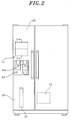
- FIG. 2 there is illustrated a schematic front plan view of a refrigerator having a temperature control apparatus installed therein for use in a carbonator of a refrigerator in accordance with a preferred embodiment of the present invention.
- the refrigerator includes a hinged freezer door 10 for closing or opening a freezer compartment 60; a carbonator 11 constituted by a box-shaped container and mounted on an inner surface of the freezer door 10; a dispenser 12 for selectively discharging a chilled water and a carbonated water; a water tank 13 for supplying water to the carbonator 11; and a carbon dioxide (CO 2 ) storage cylinder 15 for supplying carbon dioxide gas to the carbonator 11.
- CO 2 carbon dioxide
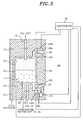
- Fig. 3 illustrates a partial cross-sectional diagram of the refrigerator shown in Fig. 2 taken along the lines 3-3 and illustrates a preferred embodiment of the present invention.
- the carbonator 11 is mounted in a recessed portion 20 formed in the inner surface of the freezer door 10.
- a water supply tube 51 for transferring water from the water tank 13 to the carbonator 11
- a gas exhaust tube 16 for discharging the carbon dioxide gas in the carbonator 11 to the outside of the refrigerator.
- a gas supply tube 54 for transferring carbon dioxide gas from the CO 2 storage cylinder 15 to the carbonator 11 and a carbonated water outlet tube 53 for transferring a carbonated water from the carbonator 11 to a nozzle 12a of the dispenser 12.
- a temperature sensor 29 Installed on an outer surface of or in the inside of the carbonator 11 is a temperature sensor 29 which detects whether the temperature of the carbonator 11 is equal to or less than a predetermined temperature and then transmits a signal to a controller 55.
- the recessed portion 20 has a size slightly greater than that of the carbonator 11 so that the carbonator 11 can be housed therein. Between the carbonator 11 and inner surface of the recessed portion 20, a plurality of protrusion members 21 made of an insulating material are disposed in such a manner that the carbonator 11 is fixedly installed in the recessed portion 20 with five sides of the carbonator 11 spaced apart from the inner surface of the recessed portion 20 while forming gaps therebetween as deep as the height of the protrusion members 21.
- a cover 30 is provided to overlay the recessed portion 20 and the carbonator 11 mounted therein.
- the cover 30 is fixed to the inner surface of the freezer door 10 by screws (not shown) or the like.
- a plurality of the protrusion members 21 are disposed to form a gap as deep as the height of the protrusion members 21 between the inner surface of the cover 30 and the back side of the carbonator 11.
- an inlet channel 25 and an outlet channel 24 are formed, respectively.
- the inlet channel 25 and the outlet channel 24 are intended for establishing communication between the recessed portion 20 and the freezer compartment 60.
- solenoid valves 26a and 26b controlled by the controller 55 are installed at the inlet channel 25 and the outlet channel 24, respectively.
- an outlet opening 125 of an outlet path (not shown) and an inlet opening 124 of an inlet path (not shown) are formed, respectively, both paths being intended for establishing communication between the recessed portion 20 and the outside of the refrigerator.
- the inlet path serves to introduce warm air outside the refrigerator into the recessed portion 20, whereas the outlet path serves to discharge the air in the recessed portion 20 to the outside of the refrigerator.
- solenoid valves 126a and 126b controlled by the controller 55 are installed, respectively.
- a fan device 31 is installed at the outlet channel 24 to forcedly discharge the air in the recessed portion 20 to the inside of the refrigerator, i.e., the freezer compartment 60.
- a separate fan device may be installed at the inlet channel 25 without or in addition to the fan device 31 to forcedly blow the cool air in the freezer chamber 60 into the recessed portion 20.
- the controller 55 controls the solenoid valves 26a, 26b, 126a and 126b in response to the signal from the temperature sensor 29. If the controller 55 receives the signal from the temperature sensor 29, the controller 55 controls the solenoid valves 26a and 26b to block the inlet channel 25 and the outlet channel 24, and controls the fan device 31 to stop its operation. Then, the supply of the cool air of the freezer compartment 60 to the recessed portion 20 is shut off so that the temperature of the carbonator 11 does not lowered.
- the controller 55 controls the solenoid valves 126a and 126b to open the outlet opening 125 and the inlet opening 124, so that the warm air outside the refrigerator is introduced into the recessed portion 20 through the inlet path and the inlet opening 124 to flow into the gaps formed between the carbonator 11 and the inner surfaces of the recessed portion 20 and the cover 30 to raise the temperature of the carbonator 11. And, the air in the recessed portion 20 is discharged to the outside of the refrigerator through the outlet opening 125 and the outlet path.
- the controller 55 controls the solenoid valves 126b and 126a to block the inlet opening 124 and the outlet opening 125, respectively, and controls the solenoid valves 26a and 26b to open the inlet channel 25 and the outlet channel 24. So, the warm air is not supplied to the recessed portion 20 from the outside of the refrigerator and the cool air in the freezer compartment 60 is supplied to the recessed portion 20 and then flows through the gaps formed between the carbonator 11 and the inner surfaces of the recessed portion 20 and the cover 30 to cool down the carbonator 11. At this time, the controller 55 controls the fan device 31 to start its operation so that the supply of the cool air from the freezer compartment 60 to the recessed portion 20 is facilitated.
- Fig. 4 is a partial cross-sectional diagram of a modified embodiment of the preferred embodiment shown in Fig. 3, wherein like parts to those of the preferred embodiment of the present invention are represented by like reference numerals, and detailed descriptions thereof will be omitted for simplicity.
- a cover 30a for overlaying the recessed portion 20 and the carbonator 11 mounted therein is provided, which is fixed to the inner surface of the freezer door 10 by screws (not shown) or the like.
- a plurality of the protrusion members 21 are disposed to form gaps therebetween as deep as the height of the protrusion members 21.
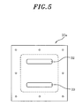
- the cover 30a has an empty inner space 37 formed therein. Further, as shown in Fig. 5, the cover 30a has an inlet through hole 32 and an outlet through hole 33 formed in an upper and lower portion of a base plate of the cover 30a, respectively.
- the inner space 37 communicates the recessed portion 20 through the inlet through hole 32 and the outlet through hole 33.
- the relatively warmer air in the recessed portion 20 flows into the inner space 37 through the inlet through hole 32 and then is cooled in the inner space 37 indirectly by the cool air of the freezer compartment 60.
- the air cooled in the inner space 37 descends to the lower portion of the inner space 37 and then flows into the recessed portion 20 through the outlet through hole.
- the carbonator 11 is then cooled down by help of the air circulation between the recessed portion 20 and the inner space 37 of the cover 30a.
- outlet opening 125 of the outlet path (not shown) and the inlet opening 124 of the inlet path (not shown) are formed at the upper and the lower portion of the recessed portion 20, respectively. As similar as in the preferred embodiment, both paths are intended for establishing communication between the recessed portion 20 and the outside of the refrigerator. And, at the outlet opening 125 and the inlet opening 124, solenoid valves 126a and 126b controlled by the controller 55a are installed, respectively.
- the controller 55a controls the solenoid valves 126a and 126b in response to the signal from the temperature sensor 29. If the controller 55a receives the signal indicating that the temperature of the carbonator 11 is equal to or less than a predetermined temperature from the temperature sensor 29, the controller 55a controls the solenoid valves 126a and 126b to open the outlet opening 125 and the inlet opening 124. Then, the warm air outside the refrigerator is introduced into the recessed portion 20 through the inlet path and the inlet opening 124. In addition, the air in the recessed portion 20 is discharged to the outside of the refrigerator through the outlet opening 125 and the outlet path. Thus, the temperature of the carbonator 11 mounted in the recessed portion 20 is raised by the warm air flowing through the gaps formed between the carbonator 11 and the inner surfaces of the recessed portion 20 and the cover 30a.
- the controller 55a controls the solenoid valves 126a and 126b to block the outlet opening 125 and the inlet opening 124, so that the carbonator 11 is cooled down by the air circulation between the recessed portion 20 and the inner space 37.
- the temperature control apparatus for use in a carbonator of a refrigerator in accordance with the present invention has a construction in which the temperature of the carbonator mounted in the recessed portion of the freezer door is controlled by the cool air inside the refrigerator and the warm air outside the refrigerator.
Landscapes
- Engineering & Computer Science (AREA)
- Chemical & Material Sciences (AREA)
- Chemical Kinetics & Catalysis (AREA)
- Combustion & Propulsion (AREA)
- Physics & Mathematics (AREA)
- Mechanical Engineering (AREA)
- Thermal Sciences (AREA)
- General Engineering & Computer Science (AREA)
- Devices That Are Associated With Refrigeration Equipment (AREA)
Applications Claiming Priority (6)
| Application Number | Priority Date | Filing Date | Title |
|---|---|---|---|
| KR2004020708 | 2004-03-26 | ||
| KR1020040020706A KR20050095343A (ko) | 2004-03-26 | 2004-03-26 | 냉장고용 탄산수 제조기 냉각장치 |
| KR2004020706 | 2004-03-26 | ||
| KR1020040020708A KR100545424B1 (ko) | 2004-03-26 | 2004-03-26 | 냉장고용 탄산수 제조기 냉각장치 |
| KR1020040020711A KR20050095348A (ko) | 2004-03-26 | 2004-03-26 | 냉장고용 탄산수 제조기의 결빙방지 구조를 갖는 냉장고 |
| KR2004020711 | 2004-03-26 |
Publications (2)
| Publication Number | Publication Date |
|---|---|
| EP1580503A1 true EP1580503A1 (de) | 2005-09-28 |
| EP1580503B1 EP1580503B1 (de) | 2008-09-03 |
Family
ID=34864973
Family Applications (1)
| Application Number | Title | Priority Date | Filing Date |
|---|---|---|---|
| EP05006582A Expired - Lifetime EP1580503B1 (de) | 2004-03-26 | 2005-03-24 | Kühlschrank ausgestattet mit einer Einheit zur Herstellung von kohlensäurehaltigem Wasser |
Country Status (2)
| Country | Link |
|---|---|
| EP (1) | EP1580503B1 (de) |
| DE (1) | DE602005009418D1 (de) |
Cited By (2)
| Publication number | Priority date | Publication date | Assignee | Title |
|---|---|---|---|---|
| WO2016024730A1 (en) * | 2014-08-13 | 2016-02-18 | Samsung Electronics Co., Ltd. | Refrigerator and controlling method thereof |
| WO2018106106A1 (en) * | 2016-12-06 | 2018-06-14 | Apiqe Holdings , Llc | Water dispensers for dispensing carbonized water and method |
Citations (4)
| Publication number | Priority date | Publication date | Assignee | Title |
|---|---|---|---|---|
| GB2160847A (en) * | 1984-05-09 | 1986-01-02 | Coca Cola Gmbh | Tapping device for postmixed drinks |
| US4866949A (en) * | 1988-11-15 | 1989-09-19 | The Coca-Cola Company | Carbonated liquid refrigeration system |
| US5484538A (en) * | 1993-09-14 | 1996-01-16 | Texavia International, Inc. | Multiple service water purifier and dispenser and process of purifying water |
| JP2005024119A (ja) * | 2003-06-30 | 2005-01-27 | Toshiba Corp | 1ドア冷蔵庫 |
-
2005
- 2005-03-24 DE DE602005009418T patent/DE602005009418D1/de not_active Expired - Fee Related
- 2005-03-24 EP EP05006582A patent/EP1580503B1/de not_active Expired - Lifetime
Patent Citations (4)
| Publication number | Priority date | Publication date | Assignee | Title |
|---|---|---|---|---|
| GB2160847A (en) * | 1984-05-09 | 1986-01-02 | Coca Cola Gmbh | Tapping device for postmixed drinks |
| US4866949A (en) * | 1988-11-15 | 1989-09-19 | The Coca-Cola Company | Carbonated liquid refrigeration system |
| US5484538A (en) * | 1993-09-14 | 1996-01-16 | Texavia International, Inc. | Multiple service water purifier and dispenser and process of purifying water |
| JP2005024119A (ja) * | 2003-06-30 | 2005-01-27 | Toshiba Corp | 1ドア冷蔵庫 |
Non-Patent Citations (1)
| Title |
|---|
| PATENT ABSTRACTS OF JAPAN vol. 2003, no. 12 5 December 2003 (2003-12-05) * |
Cited By (6)
| Publication number | Priority date | Publication date | Assignee | Title |
|---|---|---|---|---|
| WO2016024730A1 (en) * | 2014-08-13 | 2016-02-18 | Samsung Electronics Co., Ltd. | Refrigerator and controlling method thereof |
| US10473385B2 (en) | 2014-08-13 | 2019-11-12 | Samsung Electronics Co., Ltd. | Refrigerator and controlling method thereof |
| WO2018106106A1 (en) * | 2016-12-06 | 2018-06-14 | Apiqe Holdings , Llc | Water dispensers for dispensing carbonized water and method |
| NL2017940B1 (en) * | 2016-12-06 | 2018-06-19 | Apiqe Holdings Llc | Water dispensers for dispensing carbonized water |
| US11413587B2 (en) | 2016-12-06 | 2022-08-16 | Apiqe Holdings, Llc | Water dispensers for dispensing carbonized water and method |
| US11938453B2 (en) | 2016-12-06 | 2024-03-26 | Apiqe Holdings, Llc | Water dispensers for dispensing carbonized water and method |
Also Published As
| Publication number | Publication date |
|---|---|
| EP1580503B1 (de) | 2008-09-03 |
| DE602005009418D1 (de) | 2008-10-16 |
Similar Documents
| Publication | Publication Date | Title |
|---|---|---|
| KR101205822B1 (ko) | 냉각고 | |
| AU2003261562B2 (en) | Temperature control method for refrigerator | |
| JP2009525751A (ja) | キムチ冷蔵庫の冷却装置及び冷却方法 | |
| JPH10238925A (ja) | エアカーテン生成装置を利用したドアからの冷気吐出機能を有する冷蔵庫 | |
| JP2004191043A (ja) | 冷蔵庫の冷気供給装置 | |
| KR20120044560A (ko) | 이슬맺힘방지히터를 구비하는 냉장고 및 그 제어방법 | |
| KR101720488B1 (ko) | 이동식 냉장고 및 그 운전 방법 | |
| US6735975B2 (en) | Apparatus for controlling cool air of refrigerator | |
| EP1580503A1 (de) | Kühlschrank ausgestattet mit einer Einheit zur Herstellung von kohlensäurehaltigem Wasser | |
| KR102003804B1 (ko) | 생맥주 냉각장치 | |
| JP2005241139A (ja) | 冷蔵庫 | |
| CN101093124B (zh) | 一种未设置可调温隔板、具有速冷室和可开闭回风口的冷柜及其控制方法 | |
| JP3083447B2 (ja) | 冷凍冷蔵庫 | |
| JP2002302198A (ja) | 飲料ディスペンサ | |
| KR20080112710A (ko) | 냉장고 | |
| KR100443988B1 (ko) | 김치냉장고 및 그 제어방법 | |
| KR100719246B1 (ko) | 김치냉장고의 도어 냉각 장치 및 도어의 냉각 제어 방법 | |
| KR100438952B1 (ko) | 냉각장치의 냉기공급방법 | |
| JP2006242466A (ja) | 冷水供給装置付き冷蔵庫 | |
| KR20050087533A (ko) | 탄산수 디스펜서의 물통냉장장치 및 방법 | |
| KR100545424B1 (ko) | 냉장고용 탄산수 제조기 냉각장치 | |
| KR100577428B1 (ko) | 냉장고 | |
| KR100621927B1 (ko) | 비타민순환냉장고 및 이를 구현하는 비타민순환제어방법 | |
| KR20060032479A (ko) | 일체형 냉각시스템을 구비한 댐퍼개폐식 냉장고 | |
| JP2005155938A (ja) | 冷却貯蔵庫 |
Legal Events
| Date | Code | Title | Description |
|---|---|---|---|
| PUAI | Public reference made under article 153(3) epc to a published international application that has entered the european phase |
Free format text: ORIGINAL CODE: 0009012 |
|
| AK | Designated contracting states |
Kind code of ref document: A1 Designated state(s): AT BE BG CH CY CZ DE DK EE ES FI FR GB GR HU IE IS IT LI LT LU MC NL PL PT RO SE SI SK TR |
|
| AX | Request for extension of the european patent |
Extension state: AL BA HR LV MK YU |
|
| 17P | Request for examination filed |
Effective date: 20060118 |
|
| AKX | Designation fees paid |
Designated state(s): DE FR GB IT NL |
|
| GRAP | Despatch of communication of intention to grant a patent |
Free format text: ORIGINAL CODE: EPIDOSNIGR1 |
|
| GRAS | Grant fee paid |
Free format text: ORIGINAL CODE: EPIDOSNIGR3 |
|
| GRAA | (expected) grant |
Free format text: ORIGINAL CODE: 0009210 |
|
| AK | Designated contracting states |
Kind code of ref document: B1 Designated state(s): DE FR GB IT NL |
|
| REG | Reference to a national code |
Ref country code: GB Ref legal event code: FG4D |
|
| REF | Corresponds to: |
Ref document number: 602005009418 Country of ref document: DE Date of ref document: 20081016 Kind code of ref document: P |
|
| PGFP | Annual fee paid to national office [announced via postgrant information from national office to epo] |
Ref country code: NL Payment date: 20090324 Year of fee payment: 5 |
|
| PGFP | Annual fee paid to national office [announced via postgrant information from national office to epo] |
Ref country code: GB Payment date: 20090324 Year of fee payment: 5 |
|
| PLBE | No opposition filed within time limit |
Free format text: ORIGINAL CODE: 0009261 |
|
| STAA | Information on the status of an ep patent application or granted ep patent |
Free format text: STATUS: NO OPPOSITION FILED WITHIN TIME LIMIT |
|
| 26N | No opposition filed |
Effective date: 20090604 |
|
| PGFP | Annual fee paid to national office [announced via postgrant information from national office to epo] |
Ref country code: IT Payment date: 20090328 Year of fee payment: 5 Ref country code: DE Payment date: 20090427 Year of fee payment: 5 |
|
| PGFP | Annual fee paid to national office [announced via postgrant information from national office to epo] |
Ref country code: FR Payment date: 20090318 Year of fee payment: 5 |
|
| REG | Reference to a national code |
Ref country code: NL Ref legal event code: V1 Effective date: 20101001 |
|
| GBPC | Gb: european patent ceased through non-payment of renewal fee |
Effective date: 20100324 |
|
| REG | Reference to a national code |
Ref country code: FR Ref legal event code: ST Effective date: 20101130 |
|
| PG25 | Lapsed in a contracting state [announced via postgrant information from national office to epo] |
Ref country code: NL Free format text: LAPSE BECAUSE OF NON-PAYMENT OF DUE FEES Effective date: 20101001 Ref country code: FR Free format text: LAPSE BECAUSE OF NON-PAYMENT OF DUE FEES Effective date: 20100331 |
|
| PG25 | Lapsed in a contracting state [announced via postgrant information from national office to epo] |
Ref country code: DE Free format text: LAPSE BECAUSE OF NON-PAYMENT OF DUE FEES Effective date: 20101001 |
|
| PG25 | Lapsed in a contracting state [announced via postgrant information from national office to epo] |
Ref country code: GB Free format text: LAPSE BECAUSE OF NON-PAYMENT OF DUE FEES Effective date: 20100324 Ref country code: IT Free format text: LAPSE BECAUSE OF NON-PAYMENT OF DUE FEES Effective date: 20100324 |