EP1580349A2 - Tirant de coffrage - Google Patents
Tirant de coffrage Download PDFInfo
- Publication number
- EP1580349A2 EP1580349A2 EP05006064A EP05006064A EP1580349A2 EP 1580349 A2 EP1580349 A2 EP 1580349A2 EP 05006064 A EP05006064 A EP 05006064A EP 05006064 A EP05006064 A EP 05006064A EP 1580349 A2 EP1580349 A2 EP 1580349A2
- Authority
- EP
- European Patent Office
- Prior art keywords
- anchor
- formwork
- shuttering
- rider
- bump
- Prior art date
- Legal status (The legal status is an assumption and is not a legal conclusion. Google has not performed a legal analysis and makes no representation as to the accuracy of the status listed.)
- Withdrawn
Links
Images

Classifications
-
- E—FIXED CONSTRUCTIONS
- E04—BUILDING
- E04G—SCAFFOLDING; FORMS; SHUTTERING; BUILDING IMPLEMENTS OR AIDS, OR THEIR USE; HANDLING BUILDING MATERIALS ON THE SITE; REPAIRING, BREAKING-UP OR OTHER WORK ON EXISTING BUILDINGS
- E04G17/00—Connecting or other auxiliary members for forms, falsework structures, or shutterings
- E04G17/06—Tying means; Spacers ; Devices for extracting or inserting wall ties
Definitions
- the invention relates to a formwork anchor for formwork walls to be created Concrete components with an inner side of the shutter wall adjacent, arranged on a scarf wall opening by cross-tie rod Abutment for an anchor tube.
- the abutments transmit power to the shuttering walls without the cladding tubes are damaged on the front side.
- the abutments exist from conical uprising bodies, which are connected via connecting pieces in the cladding tube can be inserted and at its base the shutter wall opening caulk for the anchor rod.
- the problem is the use in Angled wall surfaces, such as coves, curved tunnel shells etc.
- the cones correspond to the installation situation cut diagonally.
- the invention is based on the object avoid the technical disadvantages and a variable connection of scarf walls with simple means to achieve. It should be the exposed concrete surfaces in the final state as free as possible of visible Be flaws.
- the invention is based on the idea of a variably bendable abutment to accomplish. Accordingly, the invention proposes that the two-piece abutment on one side of the scarf wall opening enclosing and on one of them facing away from the front Bump section with a passage opening for the anchor rod provided cone part as well as an angle-adjustable on the cusp part opposite the cone axis seated rider part for connection of the anchor tube has.
- the cone part with its cone axis always perpendicular be supported on the shuttering wall, while the rider part in align the desired angular position of the anchor rod.
- the cone part can then be easily removed, and the resulting recess can be closed by prefabricated plugs visually appealing become.
- the bump part has a passage opening limiting, in the adjustment direction circular or cylindrical convex curved Bearing surface for plain bearing of the rider's part. Accordingly, that too should Rider part have a circular concave curved counter surface, so that a pivoting adjustment under releasable positive locking is made possible.
- the passage opening is formed in the adjustment of the rider part as a slot. It should the Winkelverstell Scheme the rider part more than 20 °, preferably up to 45 °. To achieve this, it is envisaged that of the circularly curved passage opening of the bump part included angular range 45 ° + d, where d is the diameter of the anchor rod designated.
- the rider part has a in the passage opening the bump part opening receiving bore.
- the receiving bore as a stepped bore a bore section for supporting the den Anchor rod enclosing anchor sheath tube has.
- Another improvement provides that the rider part the passage opening of the bump section in each Angular position seals against concrete access.
- the rider part over laterally projecting centering ribs on mutually parallel side walls of the bump section transversely to the adjustment tilt-safe supported, so that only one degree of freedom in adjustment or swing direction remains free. It is advantageous if the centering ribs at the same time as a stop for limiting the Winkelverstell Anlagens the Rider parts are formed.
- a further advantageous embodiment provides that the cone part as a hollow part its basic shape is frusto-conical in shape, the bump section is formed on the smaller end face.
- the cone part several in the circumferential direction Distributed guide channels for engaging in the formwork wall connecting means preferably has nails or screws.
- a further advantageous embodiment provides an attachable to the rider part Connecting sleeve for a two-part anchor rod before.
- the cladding tube forms two end abutments a spacer for non-parallel shuttering walls.
- the invention is also a two-part abutment with the above Features as a supplier part for a formwork anchor.
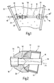
- the formwork anchor shown in the drawing allows a skewed Arrangement of spaced shuttering walls 10 for concrete components to be created 12, in particular walls with non-parallel wall surfaces.
- the device includes a the shuttering walls 10 at openings 14 by cross Thread anchor rod 16, a threaded anchor rod within the switched on Area enclosing cladding tube 18 and two to the opposite Inner sides of the shuttering walls 10 arranged on the anchor rod 16 Abutment 20 for the frontal support of the cladding 18th
- the anchor rod 16 is at its free ends via anchor closures, not shown, For example, wing nuts on the outside of the shuttering walls braced, the tension over the cladding tube 18 and the abutment 20 is recorded. This allows the hydrostatic pressure of the introduced be included in liquid concrete. Through the abutment 20 are the shutter wall openings 14 against ingress of fines of the water-cement mixture sealed. At the same time limit the cladding tube 18 and the Abutment 20 a linear continuous channel from which the anchor rod 16 can be removed again after curing of the concrete component 12.
- the two-part abutment consist respectively a cone portion 22 and one opposite to the cone axis 24 in one Adjustment direction angle-adjustable tab member 26 for connecting the jacket tube 18th
- the conical part 22 shown in Fig. 3 and 4 is in its basic form as frusto-conical hollow part, preferably as an injection molded part Plastic formed.
- the open base 28 is sealed to the edge Attachment to the inner shutter wall side provided while at the smaller End 30 a bump part 32 for storage of the rider portion 26 integrally formed is.
- the bump portion 32 has a centrally penetrated by the cone axis 24, circularly convexly curved bearing surface 34, of a passage opening 36 is broken for the anchor rod 16.
- the passage opening 36 is formed in the adjustment of the rider portion 26 as a slot. It stretches starting from the cone axis 24 to a longitudinal end of the bearing surface 34, wherein the opening area at the slot ends around the radius of the anchor rod 16 is increased. In this way, an angular adjustment the rod axis 38 opposite the cone axis 24 in a range between 0 ° and 45 ° are possible.
- the bump portion 32 is laterally of the bearing surface 34 by two parallel side walls 40 limited. These sit inside in the cup-like Base portion 42 of the cone portion 22 as stiffening webs 44 away (Fig. 4). For prefixing on the formwork wall 10 are at the base portion 42 several guide channels 46 provided for nails or screws.
- the riding member 26 shown also in Fig. 5 and 6 is in its basic form arrow-shaped truncated formed. It has one at its wider end to the bearing surface 34 of the bump portion 32 complementary mating surface 48th for angle-adjustable slide bearing. Transverse to the adjustment is the Rider part 26 on laterally projecting centering ribs 50 tip over to the Sidewalls 40 of the bump section 32 supported.
- the centering ribs 50 form in a central region at 45 ° acute angled stop lugs, at the maximum angular position of the rider portion 26 at the end face 30 of the cone part 22 strike.
- the centering ribs seal 50, the bearing surface 34 and the passage opening 36 against concrete access from.
- the rider portion 26 has a centrally continuous stepped receiving bore 52 on, the cone part 22 facing the rear portion the diameter of the anchor rod 16 and the front portion 54 at the diameter of the cladding tube 18 is adjusted.
- the receiving bore 52 opens in each angular position of the adjustment in the passage opening 36 of the bump section 32 and thus allows a straight passage of the Anchor rods 16. The occurring tensile forces are on the cone part 22 introduced at right angles into the formwork wall 10.
- the coupling sleeve 56 has end stubs 58 which are in the Cladding tube 18 and sealingly engage in the receiving bore 54.
- the anchor rod 16 thus in a Angle range between 90 ° and 45 ° to formwork wall 10 are installed.
- architecturally demanding concrete components can be constructed produce with curved surfaces.
- the releasably mounted rider portion 26 in the concrete remains.
- the resulting concrete opening can then by a corresponding Conical shaped concrete plug can be closed, so that the finished exposed concrete surface no foreign matter remain.
Landscapes
- Engineering & Computer Science (AREA)
- Architecture (AREA)
- Mechanical Engineering (AREA)
- Civil Engineering (AREA)
- Structural Engineering (AREA)
- Moulds, Cores, Or Mandrels (AREA)
- Forms Removed On Construction Sites Or Auxiliary Members Thereof (AREA)
Applications Claiming Priority (2)
| Application Number | Priority Date | Filing Date | Title |
|---|---|---|---|
| DE200410014602 DE102004014602A1 (de) | 2004-03-23 | 2004-03-23 | Schalungsanker |
| DE102004014602 | 2004-03-23 |
Publications (2)
| Publication Number | Publication Date |
|---|---|
| EP1580349A2 true EP1580349A2 (fr) | 2005-09-28 |
| EP1580349A3 EP1580349A3 (fr) | 2009-04-08 |
Family
ID=34854045
Family Applications (1)
| Application Number | Title | Priority Date | Filing Date |
|---|---|---|---|
| EP05006064A Withdrawn EP1580349A3 (fr) | 2004-03-23 | 2005-03-19 | Tirant de coffrage |
Country Status (2)
| Country | Link |
|---|---|
| EP (1) | EP1580349A3 (fr) |
| DE (1) | DE102004014602A1 (fr) |
Cited By (1)
| Publication number | Priority date | Publication date | Assignee | Title |
|---|---|---|---|---|
| DE102014211483A1 (de) * | 2014-06-16 | 2015-12-17 | Peri Gmbh | Ankerkonusvorrichtung, Schalungsanker und Betonschalungssystem |
Family Cites Families (5)
| Publication number | Priority date | Publication date | Assignee | Title |
|---|---|---|---|---|
| US2172461A (en) * | 1936-08-24 | 1939-09-12 | Anthony C Fischer | Form clamp |
| DE2904400C2 (de) * | 1979-02-06 | 1984-05-17 | Köder, Kurt, 7443 Frickenhausen | Distanzhalter zum Halten von Betonschalungswänden |
| DE29510644U1 (de) * | 1995-06-30 | 1995-09-07 | Leube, Peter, 41460 Neuss | Spannkonus für Schalungen |
| JP3024173U (ja) * | 1995-10-27 | 1996-05-17 | 丸金プラスチックス株式会社 | コンクリート壁の型板保持具 |
| JP2001279928A (ja) * | 2000-03-31 | 2001-10-10 | Spacer Kogyo:Kk | コンクリート型枠施工装置とこれに用いる埋め込みコン |
-
2004
- 2004-03-23 DE DE200410014602 patent/DE102004014602A1/de not_active Withdrawn
-
2005
- 2005-03-19 EP EP05006064A patent/EP1580349A3/fr not_active Withdrawn
Cited By (1)
| Publication number | Priority date | Publication date | Assignee | Title |
|---|---|---|---|---|
| DE102014211483A1 (de) * | 2014-06-16 | 2015-12-17 | Peri Gmbh | Ankerkonusvorrichtung, Schalungsanker und Betonschalungssystem |
Also Published As
| Publication number | Publication date |
|---|---|
| EP1580349A3 (fr) | 2009-04-08 |
| DE102004014602A1 (de) | 2005-10-13 |
Similar Documents
| Publication | Publication Date | Title |
|---|---|---|
| DE8002045U1 (de) | Wiedergewinnbares schalungsteil fuer den verankerungsbereich eines spannglieds in einem betonbauteil | |
| EP3529430B1 (fr) | Montant pour une construction à montant et traverse | |
| EP3440350B1 (fr) | Segment de tour d'éolienne avec corps de liaison et procédé de liaison de segments annulaires partiels | |
| EP1424453B1 (fr) | Manchon d'accouplement | |
| DE102009007442B4 (de) | Brücke oder Brückenabschnitt | |
| DE102007059125B4 (de) | Verankerungselement | |
| EP3330448B1 (fr) | Dispositif et procédé de raccordement de deux composants dans une orientation déterminée relative ainsi que construction en béton | |
| EP0181898A1 (fr) | Armature avec parties en acier pour constructions en beton precontraint et elements en beton precontraint prefabrique | |
| DE2553388A1 (de) | Vorgefertigter kanalisationsschacht mit rohranschlusstuecken | |
| EP0392336B1 (fr) | Dispositif employé lors du montage de coffrages pour béton | |
| DE8810423U1 (de) | Vorrichtung zur Auflagerung eines Zugglieds an einer Abstützung | |
| DE102004014602A1 (de) | Schalungsanker | |
| EP1847666A1 (fr) | Dispositif d'ancrage pour lier des planches de coffrage | |
| EP3971360A2 (fr) | Composant mural, en particulier composant mural de façade et pièce de liaison | |
| DE4324522C1 (de) | Vorrichtung und Verfahren zum Herstellen geschoßhoher Kaminelemente | |
| DE10119988B4 (de) | Verdübelungs-Vorrichtung für die Ringelemente einer Tübbingauskleidung für unterirdische Bauwerke | |
| EP0959188A2 (fr) | Element de plaque et/ou de joint en porte-à-faux pour constructions en béton armé | |
| EP3775434A1 (fr) | Bras de flèche comprenant un raccord vissé interne de support de tuyau | |
| LU502258B1 (de) | Verfahren zur Herstellung eines Röhrenkomplexes | |
| DE29614733U1 (de) | Vorrichtung zur Verankerung von Bewehrungsstäben | |
| WO2004111346A1 (fr) | Paroi de protection contre les inondations | |
| DE2322991A1 (de) | Verankerung fuer seile oder dergleichen, insbesondere fuer die spannglieder im spannbeton-bau | |
| DE202018105138U1 (de) | Seilverbindung | |
| EP0344608B1 (fr) | Elément de montage en béton pour constructions en béton précontraint | |
| DE2552736A1 (de) | Vorrichtung zur anbringung von teilen im betonbau |
Legal Events
| Date | Code | Title | Description |
|---|---|---|---|
| PUAI | Public reference made under article 153(3) epc to a published international application that has entered the european phase |
Free format text: ORIGINAL CODE: 0009012 |
|
| AK | Designated contracting states |
Kind code of ref document: A2 Designated state(s): AT BE BG CH CY CZ DE DK EE ES FI FR GB GR HU IE IS IT LI LT LU MC NL PL PT RO SE SI SK TR |
|
| AX | Request for extension of the european patent |
Extension state: AL BA HR LV MK YU |
|
| PUAL | Search report despatched |
Free format text: ORIGINAL CODE: 0009013 |
|
| AK | Designated contracting states |
Kind code of ref document: A3 Designated state(s): AT BE BG CH CY CZ DE DK EE ES FI FR GB GR HU IE IS IT LI LT LU MC NL PL PT RO SE SI SK TR |
|
| AX | Request for extension of the european patent |
Extension state: AL BA HR LV MK YU |
|
| 17P | Request for examination filed |
Effective date: 20090910 |
|
| AKX | Designation fees paid |
Designated state(s): AT BE BG CH CY CZ DE DK EE ES FI FR GB GR HU IE IS IT LI LT LU MC NL PL PT RO SE SI SK TR |
|
| 17Q | First examination report despatched |
Effective date: 20110302 |
|
| STAA | Information on the status of an ep patent application or granted ep patent |
Free format text: STATUS: THE APPLICATION IS DEEMED TO BE WITHDRAWN |
|
| 18D | Application deemed to be withdrawn |
Effective date: 20110913 |