EP3330448B1 - Dispositif et procédé de raccordement de deux composants dans une orientation déterminée relative ainsi que construction en béton - Google Patents
Dispositif et procédé de raccordement de deux composants dans une orientation déterminée relative ainsi que construction en béton Download PDFInfo
- Publication number
- EP3330448B1 EP3330448B1 EP17204467.9A EP17204467A EP3330448B1 EP 3330448 B1 EP3330448 B1 EP 3330448B1 EP 17204467 A EP17204467 A EP 17204467A EP 3330448 B1 EP3330448 B1 EP 3330448B1
- Authority
- EP
- European Patent Office
- Prior art keywords
- sleeve
- bolt
- section
- end section
- components
- Prior art date
- Legal status (The legal status is an assumption and is not a legal conclusion. Google has not performed a legal analysis and makes no representation as to the accuracy of the status listed.)
- Active
Links
- 238000000034 method Methods 0.000 title claims description 9
- 238000006073 displacement reaction Methods 0.000 claims description 8
- 230000002787 reinforcement Effects 0.000 claims description 7
- 229910000831 Steel Inorganic materials 0.000 claims description 5
- 238000003780 insertion Methods 0.000 claims description 5
- 230000037431 insertion Effects 0.000 claims description 5
- 239000010959 steel Substances 0.000 claims description 5
- 230000003014 reinforcing effect Effects 0.000 claims description 4
- 238000003466 welding Methods 0.000 claims description 3
- 238000004026 adhesive bonding Methods 0.000 claims description 2
- 238000010276 construction Methods 0.000 claims description 2
- 239000007787 solid Substances 0.000 claims description 2
- 239000000463 material Substances 0.000 description 8
- 238000013461 design Methods 0.000 description 4
- 238000009434 installation Methods 0.000 description 4
- 230000015572 biosynthetic process Effects 0.000 description 3
- 239000004570 mortar (masonry) Substances 0.000 description 3
- 238000009415 formwork Methods 0.000 description 2
- 238000004519 manufacturing process Methods 0.000 description 2
- 239000011343 solid material Substances 0.000 description 2
- 230000006978 adaptation Effects 0.000 description 1
- 150000001875 compounds Chemical class 0.000 description 1
- 238000005260 corrosion Methods 0.000 description 1
- 230000007797 corrosion Effects 0.000 description 1
- 230000001419 dependent effect Effects 0.000 description 1
- 238000005538 encapsulation Methods 0.000 description 1
- 238000005516 engineering process Methods 0.000 description 1
- 230000008014 freezing Effects 0.000 description 1
- 238000007710 freezing Methods 0.000 description 1
- 239000011796 hollow space material Substances 0.000 description 1
- 229910001220 stainless steel Inorganic materials 0.000 description 1
- 239000010935 stainless steel Substances 0.000 description 1
- 238000012549 training Methods 0.000 description 1
- 238000012546 transfer Methods 0.000 description 1
- 230000007704 transition Effects 0.000 description 1
- XLYOFNOQVPJJNP-UHFFFAOYSA-N water Substances O XLYOFNOQVPJJNP-UHFFFAOYSA-N 0.000 description 1
Images


Classifications
-
- E—FIXED CONSTRUCTIONS
- E04—BUILDING
- E04B—GENERAL BUILDING CONSTRUCTIONS; WALLS, e.g. PARTITIONS; ROOFS; FLOORS; CEILINGS; INSULATION OR OTHER PROTECTION OF BUILDINGS
- E04B1/00—Constructions in general; Structures which are not restricted either to walls, e.g. partitions, or floors or ceilings or roofs
- E04B1/38—Connections for building structures in general
- E04B1/41—Connecting devices specially adapted for embedding in concrete or masonry
-
- E—FIXED CONSTRUCTIONS
- E04—BUILDING
- E04B—GENERAL BUILDING CONSTRUCTIONS; WALLS, e.g. PARTITIONS; ROOFS; FLOORS; CEILINGS; INSULATION OR OTHER PROTECTION OF BUILDINGS
- E04B1/00—Constructions in general; Structures which are not restricted either to walls, e.g. partitions, or floors or ceilings or roofs
- E04B1/38—Connections for building structures in general
- E04B1/48—Dowels, i.e. members adapted to penetrate the surfaces of two parts and to take the shear stresses
- E04B1/483—Shear dowels to be embedded in concrete
-
- E—FIXED CONSTRUCTIONS
- E04—BUILDING
- E04B—GENERAL BUILDING CONSTRUCTIONS; WALLS, e.g. PARTITIONS; ROOFS; FLOORS; CEILINGS; INSULATION OR OTHER PROTECTION OF BUILDINGS
- E04B1/00—Constructions in general; Structures which are not restricted either to walls, e.g. partitions, or floors or ceilings or roofs
- E04B1/003—Balconies; Decks
Definitions
- the present invention relates to a device for connecting two components in a specific relative orientation with a mandrel and a first sleeve, wherein the first sleeve embedable edge flush in one of the two components and the mandrel with a first end portion in this first sleeve inserted and with his opposite, second end portion is formed for engagement in the other concrete component.
- the present invention further relates to a method for connecting two components by means of such a device in a certain relative orientation and a structure with two components of concrete connected by means of such a device in a certain relative orientation.
- Devices and methods of the type mentioned are used, for example, to align two adjoining each other at the same height balcony precast slabs, which are each connected only on one side to a building and projecting therefrom, to each other.
- the balcony slabs tend to lower under their weight to their unconnected side, with a different reduction leads to an undesirable step formation at the transition between the balcony slabs.
- With devices of the type considered can be prevented by the two components are held by the mandrel in the desired relative orientation.
- the mandrel serves merely as constructive support, i. he does not have to absorb or transfer particularly large forces.
- the devices in question are also used to form a precast wall in a desired orientation on a foundation, a bottom wall or a ceiling to fix against transverse displacements. In most cases, several such devices are used in the longitudinal direction of the precast wall. With wider balcony slabs this may also be necessary.
- the tolerances to be complied with are so small that it is not possible, already in the precast plant, to provide each sleeve with two sleeves facing each other, in which the mandrels at the installation site would simply have to be inserted.
- the recess is poured with a spout material and so said end portion fixed therein.
- the formation of cracks by shrinkage of the spout material during curing is counteracted by using a swellable mortar. This procedure has several disadvantages.
- the recess In balcony slabs, the recess must be open to the top, so that in the finished state, the spout material in the remaining material of the balcony slabs is visible. The look is not optimal.
- the encapsulation sites are also susceptible to freezing conditions. Even when using swellable mortar as a pouring material cracks may form, through which water can penetrate and possibly cause corrosion of reinforcements in the component. The mortar can only be applied at appropriate temperatures. It is necessary to wait until the pouring material has hardened until it can continue to work. Previously, supports that hold the components in the desired orientation relative to each other can not be removed.
- the EP 0059171 A1 describes a mandrel and sleeve for receiving and transmitting a transverse force.
- a connecting element for adjacent components in particular concrete, sees EP 0059171 A1 a sleeve to be inserted in a component and a mandrel embedded in the other component, which penetrates the sleeve and is displaceable in its longitudinal axis and also has a lateral movement margin transverse to the direction of force, for casual adaptation to different expansions and shrinkages of the two components .
- Mandrel and sleeve are provided at the outer end of their part to be inserted with reinforcements. The reinforcements work where the load is greatest and rises sharply towards a component edge.
- the invention has as its object to provide a device of the type considered, which avoids the disadvantages mentioned and to provide a method for aligning two components with each other with such a device and a structure provided therewith with two concrete components, which are aligned therewith.
- a device having the features of claim 1.
- This is therefore characterized in that it comprises a second sleeve, which can be embedded in the other component and in which the mandrel with its second end portion can be inserted, that of Mandrel with its first end portion in the first sleeve is rotatable about a first axis, that the mandrel in the other sleeve in a plurality of rotational positions with respect to a second axis inserted, but in the inserted state in the respective rotational position is rotationally fixed, that the mandrel in at least one the two sleeves is displaceable transversely to its respective axis, and that the second axis is aligned with lateral offset parallel to the first axis.
- the inventive design allows a prior installation of sleeves in both components, in which the mandrel at the installation needs to be inserted only in each case.
- the two sleeves need not necessarily be exactly aligned with each other in the desired alignment of the two components.
- the mutual offset of the two sleeves can in particular be greater than the play of the two end sections in their respective sleeves.
- the inventive design allows existing tolerances with respect to the alignment of the two components by simply rotating and / or moving the mandrel in the first sleeve can be compensated in a suitable rotational position.
- the complex and time-consuming pouring of the second end portion of the mandrel is eliminated with the disadvantages and problems caused thereby.
- the inventive method is characterized by the following steps: inserting the mandrel with its first end portion in the first, embedded in the first component sleeve; Partial merging of the two components in the desired orientation; Rotating and / or translating the mandrel with its end portion in the first sleeve until its second end portion is flush with the second sleeve; Inserting the second end portion in the second sleeve by longitudinal displacement of the mandrel and / or further merging of the two components to a desired Mass.
- the inventive construction with two by means of a device according to the invention in a desired relative orientation interconnected components made of concrete is characterized in that the first sleeve in the one component and the second sleeve in the second component poured into the concrete and the mandrel with its end portions in the two sleeves is inserted.
- the first end portion of the mandrel is round in cross section. He can thereby take in the first sleeve without any restrictions any rotational position.
- the first sleeve is preferably rectangular in cross section. This allows a displacement of the first end portion of the mandrel in the first sleeve in a transverse direction, namely along the longer rectangle side. In this case, when the diameter of the first end portion of the mandrel is approximately equal to the width of the rectangular cross section of the first sleeve, a largely backlash-free connection of the two components in the desired alignment is achieved.
- the second end portion of the mandrel is preferably formed in cross section as a regular n-corner. Such a shape is rotationally symmetric with respect to n discrete rotational positions.
- the second end portion of the mandrel in cross-section may in particular be hexagonal.
- the first end section of the mandrel is longer in each case in the insertion direction, preferably 2 to 3 times as long, like its second end section.
- the mandrel engages thereby still in the first sleeve when inserted into the second sleeve and thereby do not fall out during assembly.
- the material suitable for the mandrel is steel, wherein the mandrel may be made in solid material or as a hollow profile. Manufacturing technology, the two end portions of the mandrel may be connected to each other by welding, in particular by friction welding, or by gluing.
- the second sleeve in a front-side section has a plate with an opening which is a regular m-shaped cross-section.
- the number m of the corners should be equal to or greater than the number n of the cross section of the second end portion of the mandrel.
- the opening in the plate is hexagonal in cross-section, but preferably dodecagonal. In the latter case, the second end portion of the mandrel in the second sleeve can take twelve different, discrete rotational positions, which is sufficient in most applications to align the two components finely.
- the second sleeve is designed so that it widens in the insertion direction behind the front panel.
- the opening in the second plate can be dimensioned with less clearance for optimum fixation of the rotational position of the mandrel.
- the front plate of the second sleeve is preferably a steel plate to which reinforcing bars are attached as a back-up reinforcement.
- the second end portion of the mandrel in the second sleeve could be displaceable transversely to its second axis, either alternatively to a displacement of its first end portion in the first sleeve or in addition.
- Fig. 1 shows a device according to the invention with a first sleeve 10, a second sleeve 20 and a mandrel 30 with a view of the front of the first sleeve and the back of the second sleeve.
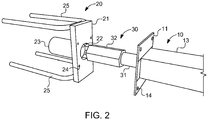
- Fig. 2 shows the three parts in the opposite direction.
- the first sleeve 10 has a front plate 11 with an opening 12 and an adjoining sleeve body 13, which is closed on the back.
- the first sleeve 10, but at least the opening 12 and the sleeve body 13, are rectangular in cross section, wherein the cross section of the sleeve body 13 preferably corresponds to the cross section of the opening 12 in the front panel 11.
- the front panel 11 is provided with four holes 14 for attachment to the inside of a concrete formwork by nailing or the like.
- the second sleeve 20 also has a front plate 21 with an opening 22 and an adjoining, rear closed sleeve body 23.
- the opening 22 in the front plate 21 is a regular polygonal cross-section with twelve corners.
- the sleeve body 23 is round and slightly widened in cross-section with respect to the cross section of the opening 22.
- the front plate 21 is made of steel and solid as the front plate 11 of the first sleeve 10.
- Reinforcing bars 25 are welded on the rear side as a repulsive reinforcement.
- Four holes 24 also allow attachment of the second sleeve 20 by nailing or the like to the inside of a concrete formwork.
- the in Fig. 3 mandrel 30, shown separately, has a first end portion 31 of circular cross section with respect to a first axis and a second end portion 32, the cross section of which is a regular polygon having six corners with respect to a second axis.
- the cross sections of the two end portions 31 and 32 are dimensioned such that they can be inserted into the sleeves 10 and 20, respectively.
- the insertion directions are in each case according to the axes and aligned.
- the FIGS. 1 and 2 show the mandrel 30 with its end portion 31 already inserted a little way into the first sleeve 10.
- the first end portion 31 of the mandrel 30 is not in alignment with its second end portion 32.
- the axes and the two end portions 31 and 32 are laterally offset from each other slightly, while aligned parallel to each other.
- the first end portion 31 of the mandrel is displaceable in this transversely to its axis along the longer sides of the rectangle, preferably by a multiple of its diameter.
- the shorter rectangular sides of the rectangular cross-section of the sleeve 10 are dimensioned so that the mandrel 30 has little play between them.
- the second, in cross-section hexagonal end portion 32 is dimensioned so that it also engages with little play in the second sleeve 20. Due to its hexagonal shape of the second end portion can be inserted in twelve different rotational positions, because of the small game but only in these twelve rotational positions in the opening 22 in the front panel 21 of the second sleeve. In the inserted state, the second end portion 32 of the mandrel 30 in the second sleeve 20 is rotationally fixed in one of the twelve possible rotational positions.
- Fig. 4 shows a kind of snapshot during assembly of the mandrel 30 in the connection of two components 40 and 50, which may be, for example, two cuboid concrete balcony slabs.
- two components 40, 50 are in Fig. 4 only opposing, parallel aligned end faces shown. Flanking at these end faces, a first sleeve 10 and a second sleeve 20 are each embedded in the concrete and indeed by pouring in the manufacture of the components 40 and 50, for example in a precast plant.
- the component 40 mounted in its desired position.
- the mandrel 30 is inserted with its first end portion 31 into the first sleeve in the first component 40, and preferably so far that only its second end portion 32 is visible.
- the second component 50 in the desired relative orientation to the first component 40 so far brought to this that its end face just does not touch the projecting second end portion 32 of the mandrel 30.
- This must now be pulled out of the first sleeve 10 a piece and inserted with its second end portion 32 in the second sleeve 20.
- the mutual offset of the two sleeves can first be compensated by turning and / or transverse displacement of the mandrel 30 in the first sleeve 10 , This works because, as described above, the two end portions 22 and 32 of the mandrel 30 are not in alignment with each other, but offset from one another laterally. After this compensation, the mandrel 30 is inserted with its second end portion 32 in the second sleeve 20.
- the second component 50 can be brought closer to the first component 40 until they touch each other or until a desired joint dimension between the two components is reached.
- any supports can be removed as a rule and further work can be carried out immediately.
- further work by the inventive compound is not hindered.
- a first Sleeve of an inventive device in the lower component for example, be installed by pouring into concrete.
- a second sleeve of the device according to the invention is already installed in the precast plant at a corresponding position.
- the dimensions suitable for the mandrel 30, in particular for the diameters of its two end sections 31, 32, depend on the expected load. If a stainless steel is used for the mandrel and the mandrel is made of solid material, suitable diameters for its first end portion 31 are in the range of 12-50 mm and for its second end portion 32 in the range of 16-80 mm. In the case of hollow material with a wall thickness in the range of 2 - 15 mm suitable diameter for its first end portion 31 in the range of 12 - 50 mm and for its second end portion 32 in the range of 16 - 80 mm. The mutual offset of the two end portions 31, 32 may be in the range of 3 - 30 mm.
- Suitable diameters for its first end portion 31 are in the range of 12-50 mm and for its second end portion 32 in the range of 16-80 mm. With an offset of 5 mm, for example, tolerances in the alignment of the two sleeves of up to 10 mm can be compensated. For the longer rectangular sides of the rectangular first sleeve 10 or its opening 12, lengths in the range 80-500 mm are suitable.
- the first end portion 31 of the mandrel 30 should be longer than its second end portion 32 a, so that the already inserted with its first end portion 31, the first sleeve 10 mandrel 30 when it is pulled out of this again a piece to its second end portion 32 in the second sleeve 20 to be inserted, still can remain inserted in the first sleeve 10.
- a length for the first end portion 31 are suitable 75-490 mm and the length of the second end portion 32 are 40-200 mm suitable. The lengths of the two sleeves 10, 20 are to be selected accordingly.
- the front plate 21 of the second sleeve 20 must be able to absorb any rotational forces exerted by the mandrel 30. It should have dimensions of 30 - 140 mm x 80-200 mm x 4-80 mm. Suitable for the reinforcing bars 25 of the back-up reinforcement are diameters of 8-25 mm and lengths of 150-1000 mm.
- a hexagonal configuration of the second end portion 32 of the mandrel 30 in combination with a dodecagonal configuration of the opening 22 in the second sleeve 20 is sufficient for most applications to provide a sufficiently fine balance of tolerances in flight of two sleeves 10 to be joined together. 20 to enable. By other geometries, in particular by more or fewer corners, the fineness of the compensation can be further increased or reduced.
- the "corners”, both on the mandrel and on the sleeve, could also be rounded so that the end portion of the mandrel in cross section, for example, an oval shape and the sleeve receives the cross section of a multi-leaved flower or the like.
- the second end section of the mandrel in the second sleeve could be displaceable transversely to its second axis.
- the width of the rectangular cross section should correspond approximately to the hexagon size. This would be possible by an example in cross-section rectangular design of the second sleeve or its front plate at the same time polygonal, for example, again hexagonal training of second end portion of the mandrel.
- the width of the rectangular cross section should correspond approximately to the hexagon size. If only the second end portion of the mandrel in the second sleeve is displaceable transversely to its second axis, the first sleeve could be a round sleeve.
Claims (15)
- Dispositif destiné à relier deux composants (40, 50) suivant une orientation relative spécifique et comprenant un mandrin (30) et un premier manchon (10),
le premier manchon (10) pouvant être incorporé dans l'un des deux composants (40) et le mandrin (30) pouvant être inséré par une première partie d'extrémité (31) dans ce premier manchon (10) et étant conçu pour s'engager, par sa deuxième partie d'extrémité opposée (32), dans l'autre composant en béton (50),
le dispositif comprenant un deuxième manchon (20) qui peut être incorporé dans l'autre composant (50) et dans lequel le mandrin (30) peut être inséré par sa deuxième partie d'extrémité (32),
le mandrin pouvant tourner, lorsque sa première partie d'extrémité est dans le premier manchon, sur un premier axe,
le mandrin (30) pouvant coulisser transversalement à son axe respectif dans l'un au moins des deux manchons (10, 20),
caractérisé en ce quele mandrin peut être inséré dans le deuxième manchon dans plusieurs positions de rotation par rapport à un deuxième axe, mais est fixé solidairement en rotation à l'état inséré dans la position de rotation respective,le deuxième axe étant orienté parallèlement au premier axe avec un décalage latéral. - Dispositif selon la revendication 1, caractérisé en ce que la première partie d'extrémité (31) du mandrin (30) a une section transversale ronde.
- Dispositif selon la revendication 1 ou 2, caractérisé en ce que le premier manchon (10) a une section transversale rectangulaire.
- Dispositif selon les revendications 2 et 3, caractérisé en ce que le diamètre de la première partie d'extrémité (31) du mandrin (30) correspond approximativement à la largeur de la section transversale rectangulaire du premier manchon (10).
- Dispositif selon l'une des revendications 1 à 4, caractérisé en ce que la deuxième partie d'extrémité (32) du mandrin (30) est un polygone régulier à n côtés en coupe transversale.
- Dispositif selon la revendication 5, caractérisé en ce que la deuxième partie d'extrémité (32) du mandrin (30) est hexagonale en coupe transversale.
- Dispositif selon l'une des revendications 1 à 6, caractérisé en ce que la première partie d'extrémité (31) du mandrin (30) est à chaque fois plus longue dans sa direction d'insertion, de préférence 2 à 3 fois plus longue, que sa deuxième partie d'extrémité (32).
- Dispositif selon l'une des revendications 1 à 7, caractérisé en ce que le mandrin (30) est en acier et est conçu en matériau plein ou sous la forme d'un profilé creux.
- Dispositif selon l'une des revendications 1 à 8, caractérisé en ce que les deux parties d'extrémité (31, 32) du mandrin (30) sont reliées l'une à l'autre par soudage ou collage.
- Dispositif selon l'une des revendications 1 à 9, caractérisé en ce que le deuxième manchon (20) comporte dans une partie frontale une plaque (21) pourvue d'une ouverture (22) qui est un polygone à m côtés en coupe transversale, en particulier un polygone régulier à m côtés.
- Dispositif selon l'une des revendications 1 à 10, caractérisé en ce que l'ouverture (22) ménagée dans la plaque (21) est hexagonale, mais de préférence dodécagonale, en coupe transversale.
- Dispositif selon l'une des revendications 1 à 11, caractérisé en ce que le deuxième manchon (20) s'élargit derrière la plaque (21) dans la direction d'insertion.
- Dispositif selon la revendication 10, caractérisé en ce que la plaque (21) est en acier et en ce que des barres d'armature (25) sont fixées à celle-ci sous la forme d'armature pendante arrière.
- Bâtiment comprenant deux composants (40, 50) en béton reliés entre eux suivant une orientation relative déterminée au moyen d'un dispositif (10, 20, 30) selon l'une des revendications 1 à 13, caractérisé en ce que le premier manchon (10) placé dans l'un des composants (40) et le deuxième manchon (20) placé dans le deuxième composant (50) sont coulés dans le béton et le mandrin (30) est inséré par ses parties d'extrémité (31, 32) dans les deux manchons (10, 20).
- Procédé de liaison de deux composants (40, 50) au moyen d'un dispositif (10, 20, 30) selon l'une des revendications 1 à 13 suivant une orientation relative déterminée, caractérisé par les étapes suivantes:insérer le mandrin (30), par sa première partie d'extrémité (31), dans le premier manchon (10) incorporé dans le premier composant (40);assembler partiellement les deux composants (40, 50) suivant l'orientation souhaitée;faire tourner et/ou coulisser transversalement le mandrin (30), avec sa première partie d'extrémité (31) placée dans le premier manchon (10), jusqu'à ce que sa deuxième partie d'extrémité (32) soit alignée avec le deuxième manchon (20);insérer la deuxième partie d'extrémité (32) dans le deuxième manchon (20) par coulissement longitudinal du mandrin (30) et/ou assembler en outre les composants (40, 50) jusqu'à un degré souhaitée.
Applications Claiming Priority (1)
| Application Number | Priority Date | Filing Date | Title |
|---|---|---|---|
| CH01576/16A CH713190A2 (de) | 2016-12-01 | 2016-12-01 | Vorrichtung und Verfahren zur Verbindung von zwei Bauteilen in einer bestimmten relativen Ausrichtung sowie damit erstelltes Betonbauwerk. |
Publications (2)
| Publication Number | Publication Date |
|---|---|
| EP3330448A1 EP3330448A1 (fr) | 2018-06-06 |
| EP3330448B1 true EP3330448B1 (fr) | 2019-08-28 |
Family
ID=60569651
Family Applications (1)
| Application Number | Title | Priority Date | Filing Date |
|---|---|---|---|
| EP17204467.9A Active EP3330448B1 (fr) | 2016-12-01 | 2017-11-29 | Dispositif et procédé de raccordement de deux composants dans une orientation déterminée relative ainsi que construction en béton |
Country Status (2)
| Country | Link |
|---|---|
| EP (1) | EP3330448B1 (fr) |
| CH (1) | CH713190A2 (fr) |
Families Citing this family (1)
| Publication number | Priority date | Publication date | Assignee | Title |
|---|---|---|---|---|
| DE202023000317U1 (de) | 2023-02-10 | 2023-04-04 | Konstantin Rühl | Aufschraubdorn zur Ausrichtung von miteinander zu verschraubenden Bauteilen |
Family Cites Families (3)
| Publication number | Priority date | Publication date | Assignee | Title |
|---|---|---|---|---|
| EP0059171B1 (fr) * | 1981-02-23 | 1986-11-12 | Ulisse C. Aschwanden | Boulon et canon pour la prise et la transmission d'une force transversale |
| ES2121637T5 (es) * | 1995-11-07 | 2006-11-16 | Nivo Ag | Dispositivo para unir y absorber fuerzas transversales procedentes de dos piezas constructivas separadas por una rendija. |
| DE102008055523B3 (de) * | 2008-12-15 | 2010-04-01 | Simon Kropmeier | Dornsystem für den Stahlbetonfertigteilbau |
-
2016
- 2016-12-01 CH CH01576/16A patent/CH713190A2/de not_active Application Discontinuation
-
2017
- 2017-11-29 EP EP17204467.9A patent/EP3330448B1/fr active Active
Non-Patent Citations (1)
| Title |
|---|
| None * |
Also Published As
| Publication number | Publication date |
|---|---|
| EP3330448A1 (fr) | 2018-06-06 |
| CH713190A2 (de) | 2018-06-15 |
Similar Documents
| Publication | Publication Date | Title |
|---|---|---|
| EP2333163A1 (fr) | Structure offshore | |
| WO2009012827A1 (fr) | Profilé d'ancrage pour boucles de câble | |
| AT519093B1 (de) | Verbindungsvorrichtung zur Verbindung von dünnwandigen Fertigteilen und damit ausgestattete Fertigteile | |
| EP3553253B1 (fr) | Montage d'un coffrage de mur, système d'ancrage et douille | |
| EP0410079A1 (fr) | Coffrage de raccordement pour panneaux en béton reliés | |
| EP2993279B1 (fr) | Construction dotée d'un élément de renfort en béton très résistant destiné à augmenter la résistance au perçage de l'estampage | |
| EP3330448B1 (fr) | Dispositif et procédé de raccordement de deux composants dans une orientation déterminée relative ainsi que construction en béton | |
| DE19923080A1 (de) | Maueranker zum Bewehren und/oder Sichern von Mauern | |
| EP2225428B1 (fr) | Élément d'ancrage | |
| CH701351A1 (de) | Kragplattenanschlusselement. | |
| EP1932978B1 (fr) | Elément d'armature pour l'absorption de forces dans des plaques de béton dans la zone d'éléments d'appui | |
| EP1702120B1 (fr) | Systeme de coffrage | |
| EP1847666A1 (fr) | Dispositif d'ancrage pour lier des planches de coffrage | |
| EP3263787B1 (fr) | Élément structural en béton préfabriqué, en particulier plaque en béton préfabriqué, ancrage de transport pour un tel élément en béton | |
| EP1101883B1 (fr) | Procédé pour la réalisation d'un raccordement d'armatures entre un élément de construction en béton et un élément de construction connecté | |
| WO2005040525A1 (fr) | Systeme de coffrage | |
| EP3299524B1 (fr) | Mur en elements prefabriques et son procede de fabrication | |
| EP3492665A1 (fr) | Pièce préfabriquée de béton dotée d'au moins un composant recevant la charge ainsi que plaque de raccordement destinée à être agencée dans le joint de raccordement entre une telle pièce préfabriquée de béton et le composant recevant la charge | |
| EP2873778A1 (fr) | Agencement de liaison et système de liaison pour pièces finies en béton | |
| EP3428356A1 (fr) | Dispositif et procédé de raccordement de deux composants ainsi qu'un composant en tant que partie du raccordement | |
| EP3702533B1 (fr) | Procédé de fixation d'une superstructure de pont et élément de bordure destiné à être utilisé à cet effet | |
| DE202015003994U1 (de) | Bauelement, insbesondere zur Errichtung von Pfeilern | |
| EP3798377B1 (fr) | Procédé de fabrication d'une construction | |
| EP0860109A2 (fr) | Eléments de construction préfabriqués et construction réalisée avec ceux-ci | |
| EP1631727A1 (fr) | Systeme d'elements de construction assembles |
Legal Events
| Date | Code | Title | Description |
|---|---|---|---|
| PUAI | Public reference made under article 153(3) epc to a published international application that has entered the european phase |
Free format text: ORIGINAL CODE: 0009012 |
|
| STAA | Information on the status of an ep patent application or granted ep patent |
Free format text: STATUS: THE APPLICATION HAS BEEN PUBLISHED |
|
| AK | Designated contracting states |
Kind code of ref document: A1 Designated state(s): AL AT BE BG CH CY CZ DE DK EE ES FI FR GB GR HR HU IE IS IT LI LT LU LV MC MK MT NL NO PL PT RO RS SE SI SK SM TR |
|
| AX | Request for extension of the european patent |
Extension state: BA ME |
|
| STAA | Information on the status of an ep patent application or granted ep patent |
Free format text: STATUS: REQUEST FOR EXAMINATION WAS MADE |
|
| 17P | Request for examination filed |
Effective date: 20181205 |
|
| RBV | Designated contracting states (corrected) |
Designated state(s): AL AT BE BG CH CY CZ DE DK EE ES FI FR GB GR HR HU IE IS IT LI LT LU LV MC MK MT NL NO PL PT RO RS SE SI SK SM TR |
|
| GRAP | Despatch of communication of intention to grant a patent |
Free format text: ORIGINAL CODE: EPIDOSNIGR1 |
|
| STAA | Information on the status of an ep patent application or granted ep patent |
Free format text: STATUS: GRANT OF PATENT IS INTENDED |
|
| RIC1 | Information provided on ipc code assigned before grant |
Ipc: E04B 1/48 20060101AFI20190201BHEP Ipc: E04B 1/00 20060101ALN20190201BHEP |
|
| INTG | Intention to grant announced |
Effective date: 20190221 |
|
| GRAS | Grant fee paid |
Free format text: ORIGINAL CODE: EPIDOSNIGR3 |
|
| GRAJ | Information related to disapproval of communication of intention to grant by the applicant or resumption of examination proceedings by the epo deleted |
Free format text: ORIGINAL CODE: EPIDOSDIGR1 |
|
| GRAL | Information related to payment of fee for publishing/printing deleted |
Free format text: ORIGINAL CODE: EPIDOSDIGR3 |
|
| STAA | Information on the status of an ep patent application or granted ep patent |
Free format text: STATUS: REQUEST FOR EXAMINATION WAS MADE |
|
| GRAR | Information related to intention to grant a patent recorded |
Free format text: ORIGINAL CODE: EPIDOSNIGR71 |
|
| STAA | Information on the status of an ep patent application or granted ep patent |
Free format text: STATUS: GRANT OF PATENT IS INTENDED |
|
| GRAA | (expected) grant |
Free format text: ORIGINAL CODE: 0009210 |
|
| STAA | Information on the status of an ep patent application or granted ep patent |
Free format text: STATUS: THE PATENT HAS BEEN GRANTED |
|
| INTC | Intention to grant announced (deleted) | ||
| RIC1 | Information provided on ipc code assigned before grant |
Ipc: E04B 1/00 20060101ALN20190709BHEP Ipc: E04B 1/48 20060101AFI20190709BHEP |
|
| AK | Designated contracting states |
Kind code of ref document: B1 Designated state(s): AL AT BE BG CH CY CZ DE DK EE ES FI FR GB GR HR HU IE IS IT LI LT LU LV MC MK MT NL NO PL PT RO RS SE SI SK SM TR |
|
| INTG | Intention to grant announced |
Effective date: 20190723 |
|
| REG | Reference to a national code |
Ref country code: GB Ref legal event code: FG4D Free format text: NOT ENGLISH |
|
| REG | Reference to a national code |
Ref country code: CH Ref legal event code: EP |
|
| REG | Reference to a national code |
Ref country code: AT Ref legal event code: REF Ref document number: 1172587 Country of ref document: AT Kind code of ref document: T Effective date: 20190915 |
|
| REG | Reference to a national code |
Ref country code: IE Ref legal event code: FG4D Free format text: LANGUAGE OF EP DOCUMENT: GERMAN |
|
| REG | Reference to a national code |
Ref country code: DE Ref legal event code: R096 Ref document number: 502017002147 Country of ref document: DE |
|
| REG | Reference to a national code |
Ref country code: NL Ref legal event code: MP Effective date: 20190828 |
|
| REG | Reference to a national code |
Ref country code: LT Ref legal event code: MG4D |
|
| PG25 | Lapsed in a contracting state [announced via postgrant information from national office to epo] |
Ref country code: PT Free format text: LAPSE BECAUSE OF FAILURE TO SUBMIT A TRANSLATION OF THE DESCRIPTION OR TO PAY THE FEE WITHIN THE PRESCRIBED TIME-LIMIT Effective date: 20191230 Ref country code: HR Free format text: LAPSE BECAUSE OF FAILURE TO SUBMIT A TRANSLATION OF THE DESCRIPTION OR TO PAY THE FEE WITHIN THE PRESCRIBED TIME-LIMIT Effective date: 20190828 Ref country code: SE Free format text: LAPSE BECAUSE OF FAILURE TO SUBMIT A TRANSLATION OF THE DESCRIPTION OR TO PAY THE FEE WITHIN THE PRESCRIBED TIME-LIMIT Effective date: 20190828 Ref country code: NO Free format text: LAPSE BECAUSE OF FAILURE TO SUBMIT A TRANSLATION OF THE DESCRIPTION OR TO PAY THE FEE WITHIN THE PRESCRIBED TIME-LIMIT Effective date: 20191128 Ref country code: FI Free format text: LAPSE BECAUSE OF FAILURE TO SUBMIT A TRANSLATION OF THE DESCRIPTION OR TO PAY THE FEE WITHIN THE PRESCRIBED TIME-LIMIT Effective date: 20190828 Ref country code: BG Free format text: LAPSE BECAUSE OF FAILURE TO SUBMIT A TRANSLATION OF THE DESCRIPTION OR TO PAY THE FEE WITHIN THE PRESCRIBED TIME-LIMIT Effective date: 20191128 Ref country code: NL Free format text: LAPSE BECAUSE OF FAILURE TO SUBMIT A TRANSLATION OF THE DESCRIPTION OR TO PAY THE FEE WITHIN THE PRESCRIBED TIME-LIMIT Effective date: 20190828 Ref country code: LT Free format text: LAPSE BECAUSE OF FAILURE TO SUBMIT A TRANSLATION OF THE DESCRIPTION OR TO PAY THE FEE WITHIN THE PRESCRIBED TIME-LIMIT Effective date: 20190828 |
|
| PG25 | Lapsed in a contracting state [announced via postgrant information from national office to epo] |
Ref country code: IS Free format text: LAPSE BECAUSE OF FAILURE TO SUBMIT A TRANSLATION OF THE DESCRIPTION OR TO PAY THE FEE WITHIN THE PRESCRIBED TIME-LIMIT Effective date: 20191228 Ref country code: RS Free format text: LAPSE BECAUSE OF FAILURE TO SUBMIT A TRANSLATION OF THE DESCRIPTION OR TO PAY THE FEE WITHIN THE PRESCRIBED TIME-LIMIT Effective date: 20190828 Ref country code: AL Free format text: LAPSE BECAUSE OF FAILURE TO SUBMIT A TRANSLATION OF THE DESCRIPTION OR TO PAY THE FEE WITHIN THE PRESCRIBED TIME-LIMIT Effective date: 20190828 Ref country code: LV Free format text: LAPSE BECAUSE OF FAILURE TO SUBMIT A TRANSLATION OF THE DESCRIPTION OR TO PAY THE FEE WITHIN THE PRESCRIBED TIME-LIMIT Effective date: 20190828 Ref country code: ES Free format text: LAPSE BECAUSE OF FAILURE TO SUBMIT A TRANSLATION OF THE DESCRIPTION OR TO PAY THE FEE WITHIN THE PRESCRIBED TIME-LIMIT Effective date: 20190828 |
|
| PG25 | Lapsed in a contracting state [announced via postgrant information from national office to epo] |
Ref country code: TR Free format text: LAPSE BECAUSE OF FAILURE TO SUBMIT A TRANSLATION OF THE DESCRIPTION OR TO PAY THE FEE WITHIN THE PRESCRIBED TIME-LIMIT Effective date: 20190828 |
|
| PG25 | Lapsed in a contracting state [announced via postgrant information from national office to epo] |
Ref country code: DK Free format text: LAPSE BECAUSE OF FAILURE TO SUBMIT A TRANSLATION OF THE DESCRIPTION OR TO PAY THE FEE WITHIN THE PRESCRIBED TIME-LIMIT Effective date: 20190828 Ref country code: PL Free format text: LAPSE BECAUSE OF FAILURE TO SUBMIT A TRANSLATION OF THE DESCRIPTION OR TO PAY THE FEE WITHIN THE PRESCRIBED TIME-LIMIT Effective date: 20190828 Ref country code: RO Free format text: LAPSE BECAUSE OF FAILURE TO SUBMIT A TRANSLATION OF THE DESCRIPTION OR TO PAY THE FEE WITHIN THE PRESCRIBED TIME-LIMIT Effective date: 20190828 Ref country code: EE Free format text: LAPSE BECAUSE OF FAILURE TO SUBMIT A TRANSLATION OF THE DESCRIPTION OR TO PAY THE FEE WITHIN THE PRESCRIBED TIME-LIMIT Effective date: 20190828 Ref country code: IT Free format text: LAPSE BECAUSE OF FAILURE TO SUBMIT A TRANSLATION OF THE DESCRIPTION OR TO PAY THE FEE WITHIN THE PRESCRIBED TIME-LIMIT Effective date: 20190828 |
|
| PG25 | Lapsed in a contracting state [announced via postgrant information from national office to epo] |
Ref country code: SM Free format text: LAPSE BECAUSE OF FAILURE TO SUBMIT A TRANSLATION OF THE DESCRIPTION OR TO PAY THE FEE WITHIN THE PRESCRIBED TIME-LIMIT Effective date: 20190828 Ref country code: CZ Free format text: LAPSE BECAUSE OF FAILURE TO SUBMIT A TRANSLATION OF THE DESCRIPTION OR TO PAY THE FEE WITHIN THE PRESCRIBED TIME-LIMIT Effective date: 20190828 Ref country code: IS Free format text: LAPSE BECAUSE OF FAILURE TO SUBMIT A TRANSLATION OF THE DESCRIPTION OR TO PAY THE FEE WITHIN THE PRESCRIBED TIME-LIMIT Effective date: 20200224 Ref country code: SK Free format text: LAPSE BECAUSE OF FAILURE TO SUBMIT A TRANSLATION OF THE DESCRIPTION OR TO PAY THE FEE WITHIN THE PRESCRIBED TIME-LIMIT Effective date: 20190828 |
|
| REG | Reference to a national code |
Ref country code: DE Ref legal event code: R097 Ref document number: 502017002147 Country of ref document: DE |
|
| PLBE | No opposition filed within time limit |
Free format text: ORIGINAL CODE: 0009261 |
|
| STAA | Information on the status of an ep patent application or granted ep patent |
Free format text: STATUS: NO OPPOSITION FILED WITHIN TIME LIMIT |
|
| PG2D | Information on lapse in contracting state deleted |
Ref country code: IS |
|
| PG25 | Lapsed in a contracting state [announced via postgrant information from national office to epo] |
Ref country code: MC Free format text: LAPSE BECAUSE OF FAILURE TO SUBMIT A TRANSLATION OF THE DESCRIPTION OR TO PAY THE FEE WITHIN THE PRESCRIBED TIME-LIMIT Effective date: 20190828 |
|
| 26N | No opposition filed |
Effective date: 20200603 |
|
| PG25 | Lapsed in a contracting state [announced via postgrant information from national office to epo] |
Ref country code: SI Free format text: LAPSE BECAUSE OF FAILURE TO SUBMIT A TRANSLATION OF THE DESCRIPTION OR TO PAY THE FEE WITHIN THE PRESCRIBED TIME-LIMIT Effective date: 20190828 |
|
| PG25 | Lapsed in a contracting state [announced via postgrant information from national office to epo] |
Ref country code: IE Free format text: LAPSE BECAUSE OF NON-PAYMENT OF DUE FEES Effective date: 20191129 |
|
| PGFP | Annual fee paid to national office [announced via postgrant information from national office to epo] |
Ref country code: FR Payment date: 20201119 Year of fee payment: 4 Ref country code: LU Payment date: 20201118 Year of fee payment: 4 |
|
| PGFP | Annual fee paid to national office [announced via postgrant information from national office to epo] |
Ref country code: BE Payment date: 20201125 Year of fee payment: 4 |
|
| PG25 | Lapsed in a contracting state [announced via postgrant information from national office to epo] |
Ref country code: CY Free format text: LAPSE BECAUSE OF FAILURE TO SUBMIT A TRANSLATION OF THE DESCRIPTION OR TO PAY THE FEE WITHIN THE PRESCRIBED TIME-LIMIT Effective date: 20190828 |
|
| PG25 | Lapsed in a contracting state [announced via postgrant information from national office to epo] |
Ref country code: GR Free format text: LAPSE BECAUSE OF FAILURE TO SUBMIT A TRANSLATION OF THE DESCRIPTION OR TO PAY THE FEE WITHIN THE PRESCRIBED TIME-LIMIT Effective date: 20190828 |
|
| PG25 | Lapsed in a contracting state [announced via postgrant information from national office to epo] |
Ref country code: HU Free format text: LAPSE BECAUSE OF FAILURE TO SUBMIT A TRANSLATION OF THE DESCRIPTION OR TO PAY THE FEE WITHIN THE PRESCRIBED TIME-LIMIT; INVALID AB INITIO Effective date: 20171129 Ref country code: MT Free format text: LAPSE BECAUSE OF FAILURE TO SUBMIT A TRANSLATION OF THE DESCRIPTION OR TO PAY THE FEE WITHIN THE PRESCRIBED TIME-LIMIT Effective date: 20190828 |
|
| PGFP | Annual fee paid to national office [announced via postgrant information from national office to epo] |
Ref country code: CH Payment date: 20211119 Year of fee payment: 5 |
|
| PG25 | Lapsed in a contracting state [announced via postgrant information from national office to epo] |
Ref country code: MK Free format text: LAPSE BECAUSE OF FAILURE TO SUBMIT A TRANSLATION OF THE DESCRIPTION OR TO PAY THE FEE WITHIN THE PRESCRIBED TIME-LIMIT Effective date: 20190828 |
|
| GBPC | Gb: european patent ceased through non-payment of renewal fee |
Effective date: 20211129 |
|
| PG25 | Lapsed in a contracting state [announced via postgrant information from national office to epo] |
Ref country code: LU Free format text: LAPSE BECAUSE OF NON-PAYMENT OF DUE FEES Effective date: 20211129 Ref country code: BE Free format text: LAPSE BECAUSE OF NON-PAYMENT OF DUE FEES Effective date: 20211130 |
|
| REG | Reference to a national code |
Ref country code: BE Ref legal event code: MM Effective date: 20211130 |
|
| PG25 | Lapsed in a contracting state [announced via postgrant information from national office to epo] |
Ref country code: GB Free format text: LAPSE BECAUSE OF NON-PAYMENT OF DUE FEES Effective date: 20211129 |
|
| PG25 | Lapsed in a contracting state [announced via postgrant information from national office to epo] |
Ref country code: FR Free format text: LAPSE BECAUSE OF NON-PAYMENT OF DUE FEES Effective date: 20211130 |
|
| P01 | Opt-out of the competence of the unified patent court (upc) registered |
Effective date: 20230512 |
|
| REG | Reference to a national code |
Ref country code: CH Ref legal event code: PL |
|
| PG25 | Lapsed in a contracting state [announced via postgrant information from national office to epo] |
Ref country code: LI Free format text: LAPSE BECAUSE OF NON-PAYMENT OF DUE FEES Effective date: 20221130 Ref country code: CH Free format text: LAPSE BECAUSE OF NON-PAYMENT OF DUE FEES Effective date: 20221130 |
|
| REG | Reference to a national code |
Ref country code: DE Ref legal event code: R081 Ref document number: 502017002147 Country of ref document: DE Owner name: PAKON AG, CH Free format text: FORMER OWNER: IKONA AG, NIEDERURNEN, CH |
|
| PGFP | Annual fee paid to national office [announced via postgrant information from national office to epo] |
Ref country code: DE Payment date: 20231121 Year of fee payment: 7 Ref country code: AT Payment date: 20231121 Year of fee payment: 7 |
|
| REG | Reference to a national code |
Ref country code: AT Ref legal event code: PC Ref document number: 1172587 Country of ref document: AT Kind code of ref document: T Owner name: PAKON AG, CH Effective date: 20231215 |